Article

Design of Parabolic Off-Axis Reflector Optical System for Large Aperture Single Star Simulators

1
College of Optoelectronic Engineering, Changchun University of Science and Technology, Changchun 130022, China
2
Key Laboratory of Optoelectronic Measurement and Control and Optoelectronic Information Transmission Technology, Ministry of Education, Changchun 130022, China
3
Jilin Optoelectronic Measurement and Control Instrument Engineering and Technology Research Center, Changchun 130022, China
*
Author to whom correspondence should be addressed.
Submission received: 17 January 2024 / Revised: 1 February 2024 / Accepted: 21 February 2024 / Published: 27 February 2024
(This article belongs to the Collection Optical Design and Engineering)

Abstract

:
This study proposes a parabolic off-axis reflective optical system design method to reduce the wave aberration of the optical system of a large aperture single star simulator and improve the optical system’s imaging quality. Firstly, we determined the design indexes of the optical system of the large aperture single star simulator by analyzing the technical indexes of the star sensitizer and the development status of the single star simulator; secondly, the initial structural parameters of the optical system were calculated based on the theory of primary aberration; then, we carried out the design optimization of the optical system, the image quality evaluation, and the tolerance analysis using Zemax software; finally, the study tested the wave aberration of the optical system by using the four-dimensional interferometer and the standard mirror together. The simulation results of the optical system are as follows: in the entire field of view, the aberration of the optical system is far less than 0.002%, the modulation transfer function (MTF) reaches the diffraction limit, and the maximum wave aberration is 0.0324 λ. The experimental results are as follows: the maximum wave aberration of the optical system is 0.0337 λ, which is less than 1/25 λ, and it meets the requirements of the index. The simulation and experimental results show that the optical system of the large aperture single star simulator designed by this method has good imaging quality and a simple system structure.

1. Introduction

Star Sensor is a high-precision space attitude measurement instrument with high accuracy, good autonomy, and independent existence without relying on other systems [1,2,3,4]. The components of the star sensitizer mainly include three aspects: the optical system, the image processing system, and the data transmission system [5,6]. Among them, the optical system, as one of the most critical components of the star sensitizer, directly impacts its ability to detect limiting stars [7]. The larger the aperture of the optical system of the star-sensitive device, the stronger the ability of the star-sensitive device to detect extreme magnitude. The star sensitizer will inevitably detect some distant, weak-magnitude stars, so the star sensitizer optical system is directed toward the direction of the development of a large aperture [8,9].
The star sensitizer, using its various control parameters and performance indicators, needs accurate measurement and debugging and due to its in-orbit test difficulty and the cost being very high, it is generally on the ground for calibration and testing. The star simulator’s emergence is precisely to achieve the star sensitizer of the performance and function of the ground calibration and testing [10,11,12]. The attitude measurement accuracy of the ground-calibrated star sensor is affected by the accuracy of the single star simulator developed in the laboratory for calibration. In order to realize the ground-based calibration and testing of star sensitizers for the detection of limiting stars, the calibration accuracy of the single star simulator, which is the ground calibration equipment, must be high. The optical system of the single star simulator generates simulated stellar images to verify the functional indexes and performance indexes of the star sensitizer, so the optical system of the single star simulator has an essential influence on the calibration accuracy of the single star simulator [13]. Therefore, to realize the high-precision ground calibration of the star sensitizer for detecting limiting stars, the aperture of the optical system of the single star simulator should be large enough, and the image quality should be good enough. In contrast, the current optical system of the single star simulator does not have these advantages simultaneously.
Some researchers and scholars have studied the design of the optical system of single star simulators. For example, Changchun University of Science and Technology [14] designed a large aperture off-axis reflective star simulator consisting of an off-axis primary parabolic mirror and a secondary plane mirror in the optical system. The optical system has an aperture of Φ300 mm, a focal length of 3000 mm, a spectral range of 500~900 nm, a field of view of 30′, an aberration of 0.0062%, and a wave phase aberration of 0.0716λ. Although the system has a large aperture, the wave aberration of the optimized system is significant, and the system imaging quality is not good enough. The Changchun Institute of Optical Precision Machinery and Physics, Chinese Academy of Sciences [15], studied a reflective single star simulator optical system designed using an off-axis parabolic mirror with a plane mirror. The focal length is 1000 mm, the aperture is Φ100 mm, the spectral range is 450~800 nm, the field of view is 3′, and the maximum wave aberration of the optical system is 0.0238 λ. Although the wave aberration of the optimized system is smaller and the imaging quality is better, the aperture of the system is smaller, and the study lacks relevant theoretical analysis and elaboration. Soochow University [16] designed a single star simulator optical system that adopts an off-axis R-C reflective optical structure. The aperture of the system is Φ250 mm, the focal length is more significant than 2500 mm, the spectral range is 400 nm to 800 nm, the maximum system wave aberration RMS is λ/22.7 (0.0441λ), and the maximum aberration value in the system is 0.18%. Although the optimized wave aberration of the system is slight, the system distortion value is not small enough, which makes the imaging shape of the system not accurate enough, and the aperture of the system is not large enough to realize the ground calibration and testing of the star sensitizer with an aperture of more than 250 mm. The primary and secondary mirrors are aspherical and challenging to process and adjust.
Comprehensively, the existing single star simulator optical systems with larger apertures do not have good enough imaging quality, and the single star simulator optical systems with better wave imaging quality have smaller apertures. Therefore, to design a large aperture single star simulator optical system with high imaging quality, this paper proposes a design scheme for a large aperture single star simulator with a parabolic off-axis reflective optical system. To achieve this goal, we determined the design parameters of the optical system of the single star simulator according to the technical specifications of the star sensitizer and the current development of the optical system of the single star simulator; then, we analyzed the parameters of the optical system to select the structure of the optical system; next, we calculated the initial structural parameters of the optical system; and then we used Zemax19.4 software to optimize the initial structure of the optical system and obtain the optical system that meets the requirements of the specifications. Then, the Zemax software was used to optimize the simulation of the initial structure of the optical system to obtain the optical system that meets the requirements of the index, and the tolerance analysis of the optical system was carried out. The wave aberration, parallelism of the emitted light, and focal length of the actual optical system meet the system’s requirements, and the optical system’s imaging quality is good, making the simulated star point image of the single star simulator more realistic and accurate. After the optical system of the single star simulator and other structural parts of the single star simulator is built, it can realize the high-precision calibration and test of the technical indexes of the star sensitizer and provide ideas for the development of the optical system of the large aperture single star simulator in the future.

2. Principle and System Parameters

2.1. Principles of Large Caliber Single Star Simulators

The computer control system regulates the luminous intensity of the light source, the light emitted by the light source through the integrating sphere after multiple reflections, in the integrating sphere out of the mouth of the light emitted with a very good surface uniformity and angular uniformity of the light. The light from the integrating sphere outlet illuminates the star point plate located at the focal plane of the collimated optical system, forming a simulated star point. The star point emission image is emitted as parallel light through the collimated optical system. The star point image of an infinite star with a certain brightness, size, and spectral distribution is obtained at the exit pupil position of the collimated optical system to realize the relevant performance test of the star sensitizer in the ground laboratory. The attenuator is located at the front of the light source and attenuates the luminous flux entering the integrating sphere. A photodetector is placed on the inner wall of the integrating sphere to monitor and give feedback on the energy of the light source at the outlet of the integrating sphere in real time to ensure the stability of the simulated stellar points. At the same time, the system can realize the simulation of different sizes of star points by switching the star point plate with different diameters of star point holes. The system structure is shown in Figure 1.
This paper studies the collimated optical system part of the large aperture single star simulator. The collimated optical system is mainly composed of parabolic mirrors and plane mirrors; the primary mirror quoted parabolic mirrors to improve the system image quality, and the secondary mirror quoted plane mirrors are used to fold the optical path to reduce the size of the system. The inner wall of the optical system is blackened, and a stray light suppression diaphragm is set in the optical system to reduce the stray light. The optical system of the large aperture single star simulator designed in this paper has good imaging quality, which improves the simulation accuracy of the star points of the large aperture single star simulator star.

2.2. Analysis of System Indexes and Determination of Main Parameters

The operating spectral range of the optical system of the star sensitizer is jointly determined by the spectral range of the star to be detected and the spectral response range of the CCD [17]. Due to the long distance of the star, the wavelength of the light emitted is generally concentrated between 400 and 600 nm. Normally, the spectral range of the star sensitizer should cover the band of stellar light to ensure that the star sensitizer can effectively detect the light signal of the star, so the spectral range of the optical system of the star sensitizer is selected in the band of 450~850 nm [18]. Specifically for the single star simulator optical system designed in this paper, it is determined that its operating band is 450~850 nm, and the center wavelength is 632.8 nm.
According to the principle of optical pupil articulation, the exit pupil of the star simulator optical system should coincide with the entry pupil of the star sensitizer optical system. If the exit pupil diameter of the star simulator optical system is smaller than the entry pupil diameter of the star sensitizer optical system, it will lead to energy loss [19]. Therefore, to minimize the energy loss, the aperture of the star simulator should be larger than the aperture of the star sensitizer. The aperture size of the star sensitizer needs to match the detection sensitivity of the selected sensor, and in general, increasing the aperture helps to increase the limiting magnitude of detection [20]. The aperture size of the optical system of a star sensor capable of detecting 15 magnitudes is 250 mm [21], and the aperture of the optical system needs to be larger if the star sensor is to detect higher magnitudes. To realize the ground simulation and test work of the star sensor with higher detection capability, combined with the development of single star simulators, this paper will design a single star simulator optical system with a larger aperture. Therefore, the aperture of the optical system designed in this paper is selected as 500 mm.
The focal length of the optical system is calculated by Equation (1):
F = f D
where F for the optical system F-number, D for the optical system aperture, f for the optical system focal length. The F-number determines the degree of difficulty of the optical system design [22]; after comprehensive consideration, the F-number is determined as 10. The aperture is selected as 500 mm by calculating the focal length of 5000 mm.
According to the actual working requirements, this optical system’s smaller field of view can meet the use requirements. To facilitate the installation and commissioning, the diameter of the simulated star point is selected as φ200 μm, the diameter of the star point hole is selected as φ200 μm, and the field of view of the optical system is calculated to be 0.01° by Equation (2) to meet the requirements.
θ = 2 arctan d / 2 f
From the Rayleigh criterion, when the maximum wave aberration in the optical system is less than or equal to 1/4λ, it can be considered that the imaging quality of the optical system reaches the ideal level [16]. Therefore, the smaller the wave aberration of the optical system is, the better the imaging quality of the optical system is. The better the imaging quality of the optical system of the single star simulator, the closer the simulated star point is to the real star. The test and calibration of the star sensitizer are more accurate. Combined with the current development of single star simulators, the optical system designed in this paper is required to have a wave aberration of less than 1/25λ.
The design index requirements for the optical system of the large aperture single star simulator are shown in Table 1.
The optical system index data shows that the system has a larger aperture and a longer focal length while the relative aperture is smaller. Therefore, choosing a two-mirror system is relatively simple, and the commonly used two-mirror systems are reflective and refractive–reflective two-mirror systems [23]. Chromatic aberration is difficult to avoid due to the inconsistent transmission of the lens to different wavelengths. In contrast, the reflective system does not produce chromatic aberration since the beam does not transmit through the lens. The lens material limits the wavelengths of refractive–reflective and transmissive systems, while reflective systems can be used in broader spectrum optical systems by coating the mirrors with suitable materials [24]. The structure of off-axis two mirrors was chosen for the system design since there can be no obstruction in the system center. Additionally, due to the small field of view of the optical system of this single star simulator, one parabolic reflector was chosen for the system design [25,26]. The theoretical study, simulation design, and experimental verification of the parabolic off-axis reflective optical system are carried out in the following.

3. Initial Structural Parameter Calculation and Design Optimization Process

3.1. Calculation of System Structure Parameters

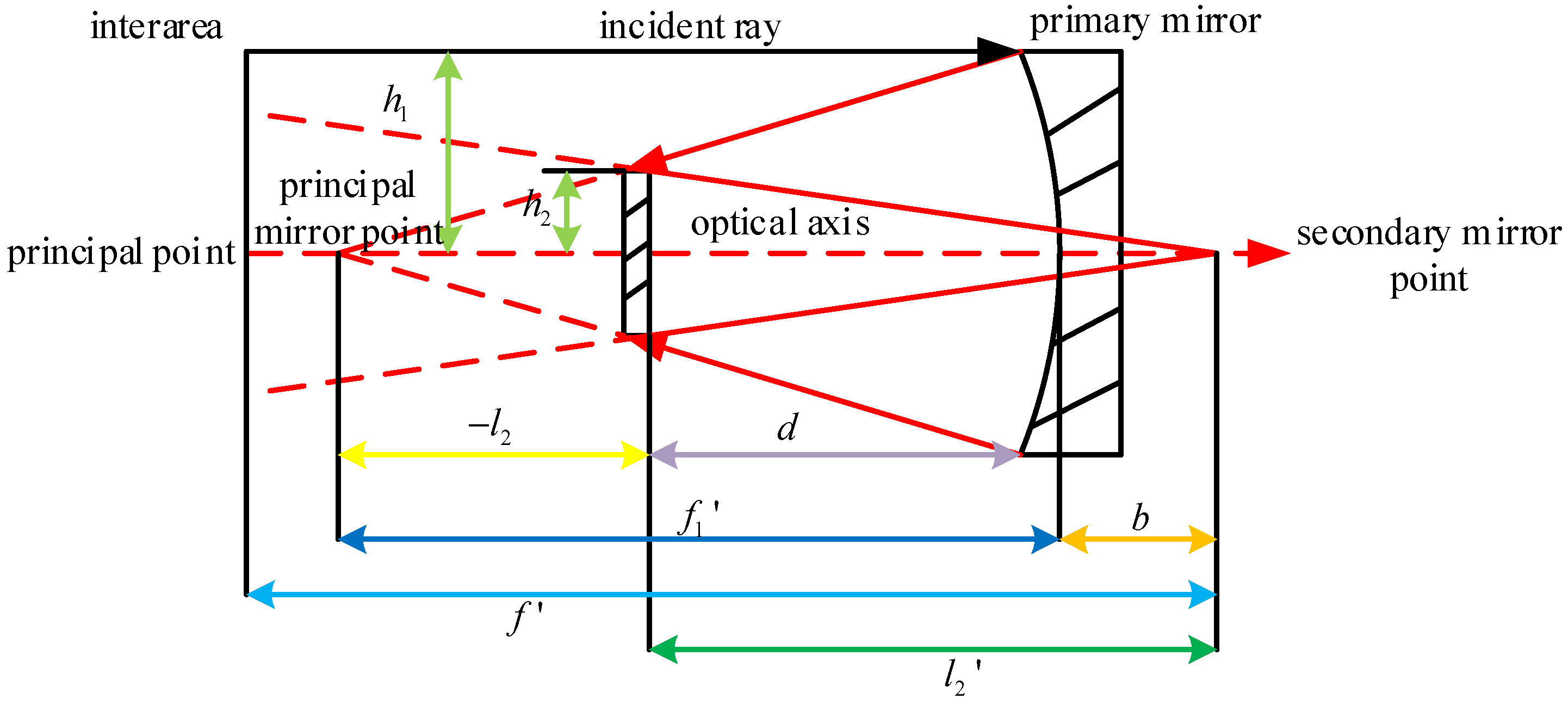
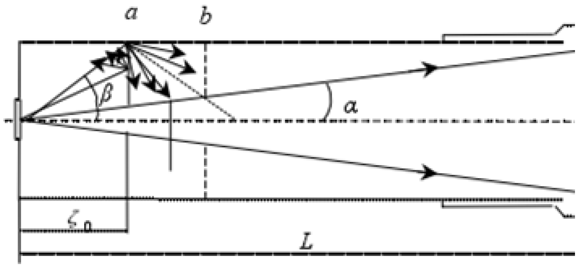
When designing the off-axis reflective system, it is necessary to design the co-axial system with shielding because the center is not shielded, as shown in the formula in Figure 2. According to the design index requirements, the optical system’s initial structural parameters are solved using the primary aberration theory. For the center of the obstruction, the field of view or aperture diaphragm is off-axis to keep it away from the obstruction. Finally, the off-axis reflective system without obstruction is obtained by optimizing the system [27].
The primary mirror of this system uses a paraboloid, which is a quadratic surface, and the expression of the quadratic surface is shown in Equation (3).
y 2 = 2 R 0 x 1 e 2 x
In Equation (3), R0 is the radius of curvature of the mirror vertex; e2 is the face shape parameter of the reflector, which can be used to eliminate aberration when used as an optimization variable.
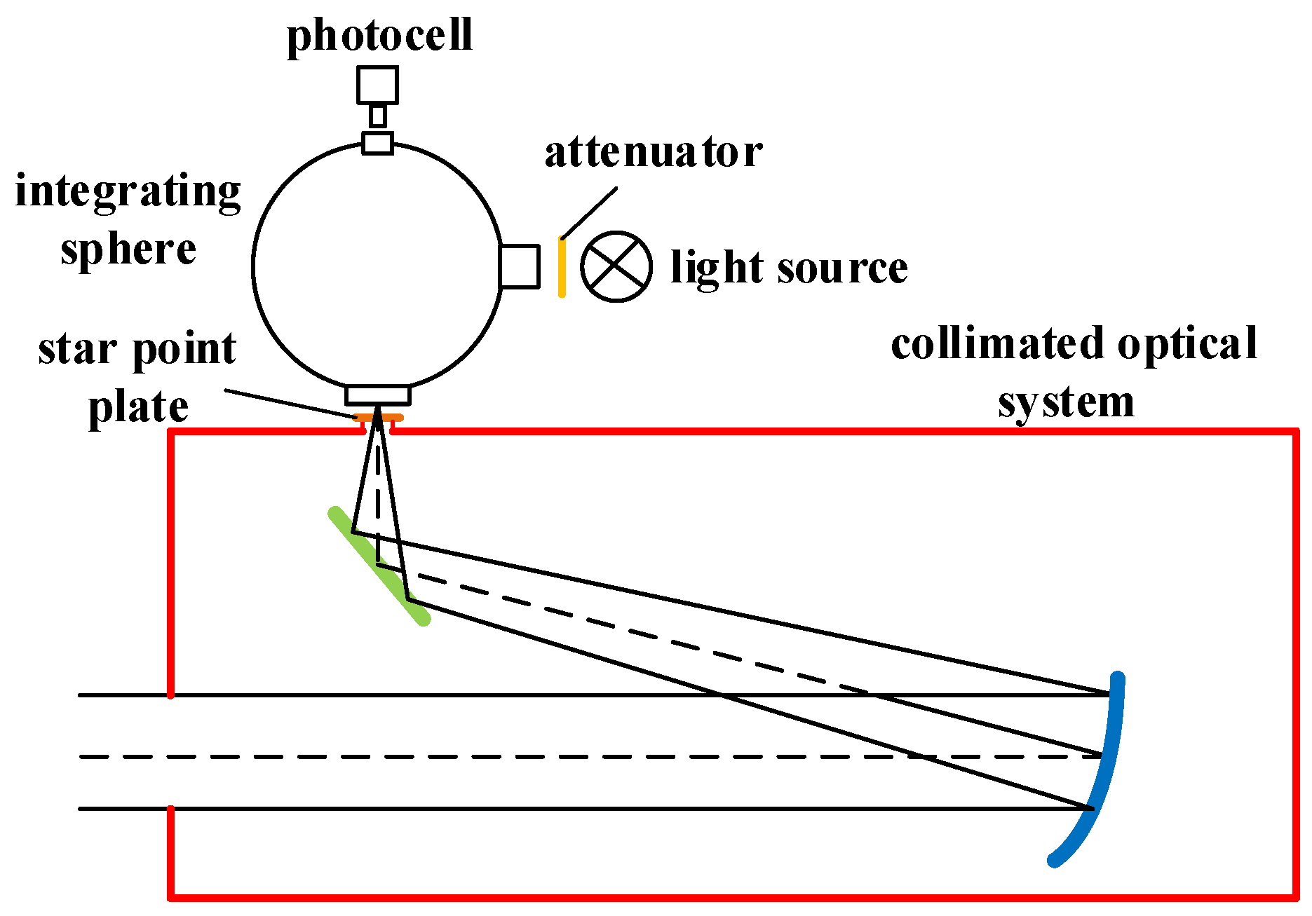
The collimation system of a single star simulator is meant to simulate stars at infinity. Therefore, the design structure of the telescope system can be used in the design of the star point simulation optical system. Thus, the single star simulator optical system satisfies the following two conditions:
(a) The object is located at infinity, l 1 = , u 1 = 0 ;
(b) The diaphragm is located on the primary mirror, x 1 = y 1 = 0 .
According to Figure 2, the expressions for the blocking ratio α of the system and the magnification β of the secondary mirror are shown in Equation (4).
α = l 2 f 1 h 2 h 1 β = l 2 l 2 f f 1
where h 1 and h 2 denote half of the aperture of the primary and secondary mirrors, respectively; f 1 and f 1 denote the focal length of the primary mirror and the focal length of the star simulation optical system, respectively; l 2 and l 2 denote the distance between the secondary mirror and the object and the distance between the secondary mirror and the image, respectively.
According to the structural design of the co-axial system, the expression of the secondary mirror object distance l 2 can be known from the structure of the two-mirror system, as shown in Equation (5).
l 2 = f 1 + Δ β 1
where Δ is the focal point protrusion of the optical system. Since the shade ratio of the system will be directly affected by the focal point outreach of the system, after comprehensive consideration, the focal point outreach can be temporarily determined as Δ = 200 mm.
Knowing the relationship between the radius of curvature R1 of the primary mirror’s vertex and the primary mirror’s focal length, the radius of curvature R2 of the vertex of the secondary mirror is calculated using Gauss’s formula, as shown in Equation (6).
R 1 = 2 f 1 R 2 = α β 1 + β R 1
According to the primary phase aberration theory, the expressions for spherical aberration (S1) and wise aberration (S2) in a reflective optical system are shown in Equation (7).
S 1 = α β 1 2 β + 1 4 α β + 1 3 4 e 2 2 β 3 4 1 e 1 2 S 2 = 1 α α α β + 1 3 4 β e 2 2 α β 1 2 β + 1 4 β e 2 2 1 2
Due to the co-axial system, it is necessary to satisfy the condition of the spherical aberration S1 and the wisp aberration S2. This requires S1 = 0 and S2 = 0 in the reflection optical aberration to find the primary mirror face type coefficient e12 and secondary mirror face type coefficient e22, as shown in Equation (8).
e 1 2 = 1 + 2 α 1 α β 2 e 2 2 = 2 β 1 α + 1 + β 1 β 2 1 + β 3
According to the structural parameters of the co-axial system can be calculated the distance d between the primary and secondary mirrors, known as primary mirror through the light aperture D1, can be derived from the approximate range of values of the axial quantity Sx, as shown in Equation (9).
d = f 1 l 2 = f 1 1 α S x D 1 R 1 d 2 d
The primary mirror of this optical system is a parabolic reflector, and the secondary mirror is a planar reflector. Combining the design index of the optical system and the above formula to solve the initial structural parameters of the optical system, we get the initial structural parameters of the optical system: R1 = 10,000 mm, R2 = 0, e12 = 1, e22 = 0, d = −3200 mm, and initially select the system off-axis amount Sx = 300 mm.

3.2. System Design Optimization Process

After the basic parameters of the optical system (pupil diameter, field of view, spectral range) are set up in Zemax software, the initial structure data of the optical system obtained in Section 3.1 are input into the lens data to complete the simulation of the initial structure of the optical system by ZEMAX. The image quality of the initial structure of the optical system is poor and needs to be optimized. The optimization process is as follows.
Firstly, the radius of curvature of the optical system is selected as the optimization variable to optimize the optical system because the radius of curvature is easier to control, there are no excessive requirements, and the optimization results are more obvious. Then, other parameters such as mirror spacing, glass thickness, and aspheric coefficient are selected as the optimization var.
After completing the previous step, the image quality of the initial structure of the optical system is improved. Next, the optimization function editor is opened, and the optimization operands are entered for optimization. The optimization operands set are focal length (EFFL), local ray Y coordinate (REAY), arc vector field curve (FCGS), meridian field curve (FCGT), and coma (COMA). At this point, the initial structure data and optimization parameters are basically inputted completely. Both the radius of curvature and the aspheric coefficient are set as variables for optimization, and the image quality of the optical system disposal structure is further improved.
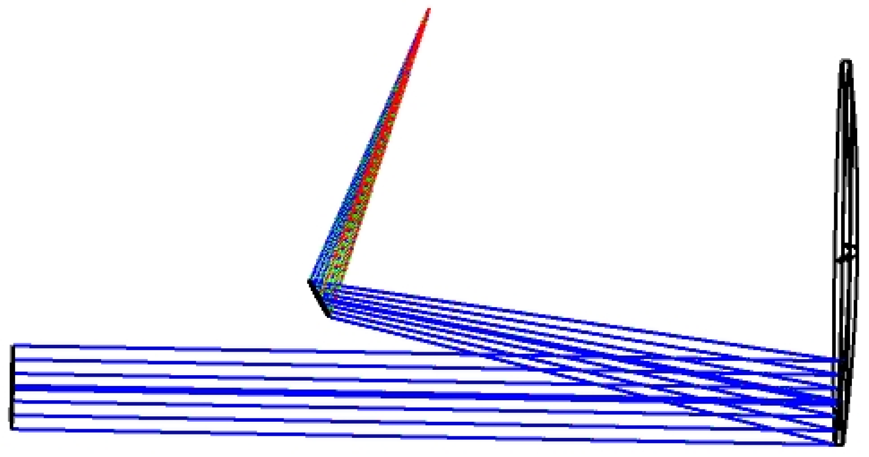
Finally, the primary mirror is designed off-axis based on the co-axial optical system. The calculation in the previous section selects a suitable off-axis amount, and here, the off-axis amount of the primary mirror is taken as −300 mm. In the software, a line is inserted into the column above the primary and secondary mirrors, respectively, and the surface type is selected to be “Coordinate Break,” which establishes a breakpoint to facilitate the off-axis design. For one of the primary mirror breakpoint lines behind the “Decenter Y” column, enter −300; select the two mirror breakpoint lines. “Tilt About X” is set as a variable for optimization. At the same time, the primary mirror off-axis amount and primary and secondary mirror tilt are set as a variable; the optical system will be optimized until it meets the requirements of the system design index.

4. Parabolic Off-Axis Reflective Optical System Design

4.1. Optical System Design Results

The design of the optical system is optimized using Zemax software, and the structure of the optimized parabolic off-axis reflective optical system is shown in Figure 3.

4.2. Optical System Image Quality Evaluation

The single star simulator optical system design should satisfy the design requirements of smaller image plane dispersion spots, higher energy concentration, larger transfer function values, and smaller wave aberration [28,29]. The evaluation criteria of its imaging quality include spot diagrams, field curves and distortion, MTF curves, energy concentration curves, system wave aberration plots, and so on.
The spot diagram of the optical system is shown in Figure 4, and the RMS radius and geometric radius of the point-list diagram for each field of view are given in Table 2. From Table 2, it can be seen that the diameter of the diffuse spot in each field of view is small, and the diameter of the diffuse spot increases with the increase of the field of view angle, and the diameter of the diffuse spot in the 0° center field of view is always smaller than that of the diffuse spot in each other field of view. In the full field of view, the maximum RMS radius is 2.604 μm, which is much smaller than the Airy spot radius of 7.677 μm.
Combining the point spread function of the optical system (shown in Figure 5), the radiant energy distribution map (shown in Figure 6), and the geometric energy concentration curve (shown in Figure 7) provides insight into issues such as the energy of the star-spot like the image of the optical system, the shape distribution, and the diffraction situation. The point diffraction function describes the spatial distribution of the spot like light source after propagation in the optical system (spatial mode). As can be seen in Figure 6, the energy center of a standard single star is mainly affected by the diffraction situation. Combined with Figure 7, it can be seen that the energy concentration of each field of view is greater than 85% in a region with a diameter of 20 μm, which meets the requirements for use.
The field curvature aberration of the system reflects the degree of curvature of the imaging surface, indicating that light rays emitted from different fields of view cannot converge on the same plane. Therefore, excessive field curvature will lead to blurred imaging of the system, and the field curvature and distortion of the optical system are shown in Figure 8. The field curvature of the system is very small and negligible. In addition, the distortion of the system is much less than 0.002% and does not affect the actual measurement.
The transfer function curve of the optical system is shown in Figure 9. The MTF of the optical design is an important index to analyze the excellent or bad imaging quality of the system, and the larger the MTF is, the better the imaging quality of the system is. As can be seen from the figure, the optical transfer function of each field of view of the system is more concentrated, and the line is smooth and close to the diffraction limit. The wave aberration diagram of the optical system is shown in Figure 10. The wave aberration of the system is no more than 0.0324λ in the entire field of view, which meets the requirement of wave aberration of less than 1/25λ, and the imaging quality of the optical system is good.
In summary, this paper realizes the design of a parabolic off-axis reflective optical system with an aperture of Φ500 mm, a focal length of 5000 mm, and a spectral range of 450 nm~850 nm. Through the image quality analysis, it can be seen that the optimization results of the optical system meet the requirements of the design index, and the imaging quality of the system is good.

4.3. Tolerance Analysis

For an optical system, the actual processing and mounting processes will introduce certain errors, which will reduce the overall imaging performance compared to the theoretical value. Therefore, to ensure that the image quality still meets the requirements after the system is processed and mounted, it is necessary to analyze the tolerance of the completed optical system to assess the feasibility of actual mounting. Optical system tolerances are mainly manufacturing tolerances and mechanical assembly tolerances, and the tolerances of the optical system are assigned according to the requirements of the measurement accuracy index of the large aperture single star simulator, as shown in Table 3.
The MTF is used as the evaluation standard to analyze the sensitivity of this optical system. From the analysis, it can be seen that the first six tolerances affecting the MTF value of the optical transfer function of the system are shown in Table 4. TETY is the element Y-direction tilt tolerance, TETX is the element X-direction tilt tolerance, and TTHI is the element thickness and air spacing tolerance. From the results of the tolerance sensitivity analysis, the corresponding parameter structures of the MTF of the tolerance-influenced system are the distance L between the planar mirror M1 and the parabolic mirror M2, the X-direction and Y-direction tilting of the planar mirror M1, and the X-direction tilting of the parabolic mirror M2, which are mainly caused by the relative positions of the two mirrors. All of the above tolerances are related to assembly and need to be guaranteed by assembly accuracy.
Finally, the Monte Carlo analysis method is used to evaluate the tolerance and analyze the comprehensive performance of the optical system. After analyzing 1000 Monte Carlo samples, each of which is a simulation of an actual optical system after machining and mounting, the statistical results of MTF are obtained, as shown in Table 5. The analysis results show that according to the tolerance assignment in Table 3, after processing and mounting, the MTF of more than 98% of the optical system is greater than 0.6966, the MTF of more than 90% of the optical system is greater than 0.7113, the MTF of more than 80% of the optical system is greater than 0.7193, the MTF of more than 50% of the optical system is greater than 0.7302, the MTF of more than 20% of the optical system is greater than 0.7372, the MTF of more than 10% optical system is greater than 0.7396, and the MTF of more than 2% optical system is greater than 0.7418. With this tolerance assignment, the image quality meets the technical requirements of the system design, and the tolerance assignment is reasonable, which can be realized by engineering.

4.4. Optical System Stray Light Suppression

The optical system of a large aperture single star simulator is different from the imaging system, and its stray light mainly originates from the multiple scattering inside the system, i.e., the perturbation of endogenous stray light. Through the analysis, we use in the optical system set up stray light suppression diaphragm as well as the box inside and isolation platform and other blackening treatments to suppress the system stray light.
According to the results of the optical system design, the distance L from the small aperture to the first face of the objective lens is 973 mm, the secondary mirror aperture is Φ255 mm, the radius tensor angle of the objective lens to the small aperture is about 2.94°. The radius angle of the beam exiting the small aperture is about 90°, and many non-imaging beams exist in the optical system. In order to avoid non-imaging beams in the optical system scattering light out of the objective lens, it is necessary to set the aperture in the optical system stray light suppression diaphragm. Stray light suppression diaphragm through the size of the aperture to not block the imaging beam shall prevail, as shown in Figure 11, but the aperture diaphragm can have a sound effect; the location of the determination is critical.
If the stray light suppression diaphragm is located in position b or further away from the small aperture plate in Figure 11, there will be diffuse reflection in the main direction of light through the stray light suppression diaphragm into the back of the system; if the stray light suppression diaphragm is located in Figure 2, between a, b, the diffuse reflection in the main direction of light will not be transmitted through the stray light suppression diaphragm, but a diffuse reflection of the second direction of the light is still able to pass through the stray light suppression diaphragm (shown by dotted lines in the figure). If the stray light suppression diaphragm is located in position a or closer to the small aperture plate, then a diffusely reflected light will not pass through the stray light suppression diaphragm, and the second diffuse reflection occurs in the wall of the optical system, so that in the stray light through the stray light suppression diaphragm before it has been many times before the attenuation, so the stray light suppression diaphragm can be located in position a. The distance from the star point plate to the stray light suppression diaphragm is calculated as shown in Equation (10).
tan α = d 2 ξ 0 tan β = D 2 ξ 0
where d is the aperture of the secondary mirror, D is the aperture of the light source edge light and is the distance from the star point plate to the stray light suppression diaphragm.
Star point plate in the star point opening position for the initial origin, the use of Formula (1) to calculate the stray light suppression diaphragm center hole to the origin of the distance and the diameter of the opening as shown in Table 6.
The specific parameters of the optical properties of the optical and structural elements set in the optical system are shown in Table 7. The surfaces of the primary and secondary mirrors are set to actual reflection characteristics, while the optical properties of the surfaces of the primary and secondary mirror mechanical structures, the surfaces of the stray light suppression diaphragm 1~3 mechanical structures, the inner surface of the box, and the optical vibration isolation platform are set to blackening characteristics.
After processing the optical system according to the above method, it can play a good role in suppressing non-imaging beams with clear directionality and irregular stray light. The remaining stray light after suppression has a negligible effect on the system index, and the system meets the use requirements.

5. Experimental Verification

The primary mirror and secondary mirror were processed, and the finished physical images of the primary mirror and secondary mirror are shown in Figure 12a and Figure 12b, respectively. The main mirror is made of microcrystalline glass. The supporting material and method of the main mirror are as follows: the back of the main mirror and the frame are bonded into a whole with non-stress adhesive, surrounded by polytetrafluoroethylene paper, and fixed with a gland. The material of the second mirror is fused quartz. The supporting material and method of the secondary mirror are as follows: the secondary mirror and the frame are isolated by polytetrafluoroethylene, and the gland is fixed. The reflector is coated with a custom high-reflection film, with a reflectance of up to 99% in the 400 nm to 900 nm spectral range.
The parabolic off-axis reflection optical system is constructed in the laboratory environment, and the completed parabolic off-axis reflection optical system is shown in Figure 12c. Then, the optical system’s wave aberration, parallelism, and focal length are measured.

5.1. Wave Aberration Test of Optical System

Wave aberration of an optical system is a critical technical index to measure the imaging quality of an optical system. The parabolic off-axis reflection optical system’s wave aberration is tested using a four-dimensional interferometer and standard mirror. The selected four-dimensional interferometer model is PhaseCam 4020, as shown in Figure 13, and its technical specifications are shown in Table 8.
The principle of wave aberration measurement of optical system is as follows: the interferometer provides a plane or spherical test wave (determined by the optical system to be measured), generates a plane wave through the measured optical system, the light is vertically incident on the standard plane mirror, the wave surface self-collimation reflection, returns to the interferometer, forms the wave surface of the optical system to be measured, and thus obtains the wave aberration of the optical system [30]. The wave aberration test principle diagram is shown in Figure 14, and the wave aberration diagram obtained by the test is shown in Figure 15. The actual wave aberration of the optical system has been measured four times, and the measurement results are shown in Table 9.
According to Table 9, it can be seen that the average value of wave aberration of the optical system is 0.0337λ, and the maximum value is 0.0359λ, which is less than 1/25λ and meets the requirements of the system index.

5.2. Parallelism Test of the Optical System

For a single star simulator, the optical system of the emitted light parallelism requirements are high; therefore, this paper uses the latitude and longitude instrument for the optical system of the emitted light parallelism of the actual test, the latitude and longitude instrument as shown in Figure 16, and the main technical parameters as shown in Table 10.
The specific test method is as follows. The pentaprism is placed on the support in front of the primary mirror of the optical system, and the outgoing light is irradiated to the pentaprism. The theodolite receives it after reflection. The pentaprism moves smoothly along the direction perpendicular to the optical axis of the optical system. During the movement, if the center of the star spot received by the theodolite has a deflection angle, the angle is the parallelism of the outgoing light of the collimating optical system. After many measurements, the measured parallelism results are shown in Table 11.
It can be seen from Table 11 that the parallelism of the outgoing light measured by the theodolite optical system is all less than 1″, and the parallelism of the outgoing light of the optical system of the single star simulator meets the technical requirements.

5.3. Focal Length Test of Optical System

In the optical system focal length test, the theodolite and Bolo plate are used to coordinate each other. The theodolite is placed at the optical outlet of the optical system, and the Bolo plate is placed at the focal plane position of the optical system. Using theodolite to aim at the engraved lines on the Bolo plate, observe the line pairs with a spacing of 10 mm on the Bolo plate, record the azimuth angle difference between the lines at this moment, and then calculate the focal length value by using the focal length calculation formula.
f = L / 2 tan ( θ / 2 )
where L is the distance between pairs of lines on the Bolo plate, and θ is the azimuthal angle difference between the lines at this moment. Repeatability measurements were taken for each test result, and the obtained test values were recorded. The results of the focal length test are shown in Table 12.
From Table 12, it can be obtained that the measured focal length value of the optical system is 5007.131 mm, which is more than 5000 mm after taking the average value and meets the requirements of the technical specifications.

6. Conclusions

In this paper, we propose a parabolic off-axis reflective optical system design method to improve the imaging quality of the optical system of a large aperture single star simulator and realize the star sensitizer’s ground test and calibration work for detecting the limiting stars, and so on. The optical system has an aperture of Φ500 mm, a focal length of 5000 mm, a spectral range of 450~850nm, and meets the image quality requirement of wave aberration less than 1/25λ. Among them, the primary mirror of the system adopts a parabolic reflector, and the secondary mirror adopts a planar reflector. The system has no center blocking and is compact. The optimized optical system distortion is much less than 0.002%, the maximum system wave aberration is 0.0324λ, and the MTF reaches the diffraction limit. The maximum value of the actual wave aberration of the system is 0.0359λ, and the system has good imaging quality. Compared with the refractive optical system, the off-axis triple reflective optical system, and the reflective optical system using free-form surfaces, the design of this optical system has obvious advantages: firstly, it effectively reduces the difficulty of processing and assembling the system, which makes the manufacturing and assembling process simpler and more economical; secondly, it effectively reduces the wave aberration of the optical system and improves the imaging quality of the optical system, which in turn improves the clarity and accuracy of the imaging. The single star simulator optical system designed in this paper, namely the stellar star point simulation system, can realize the high-precision simulation of stellar star point images. Therefore, the single star simulator optical system designed in this paper and other structural parts of the single star simulator can realize the high-precision calibration and testing of the technical index of the star sensitizer, which is of great significance to the research and development of the single star simulator optical system for calibration.

Author Contributions

Conceptualization, T.G., G.S. and Z.D.; methodology, T.G., G.S. and Q.L.; software, T.G. and Q.D.; resources, G.S. and G.Z.; data curation, T.G.; validation, T.G. and G.S.; formal analysis, investigation, and writing, T.G.; review and supervision, S.C. and J.Z. All authors have read and agreed to the published version of the manuscript.

Funding

This research was funded by the National Natural Science Foundation of China (61703057), Jilin Provincial Science and Technology Development Program (20210201034GX), and Jilin Provincial Innovative and Entrepreneurial Talent Funding Program (2023QN13).

Institutional Review Board Statement

Not applicable.

Informed Consent Statement

Not applicable.

Data Availability Statement

Data are contained within the article.

Conflicts of Interest

The authors declare no conflicts of interest.

References

  1. Mao, X.; Du, X.; Fang, H. Precise attitude determination strategy for spacecraft based oninformation fusion of attitude sensors: Gyros/GPS/Star-sensor. Int. J. Aeronaut. Space Sci. 2013, 14, 91–98. [Google Scholar] [CrossRef]
  2. Wang, W.; Wei, X.; Li, J.; Wang, G.Y. Noise suppression algorithm of short-wave infrared star image for daytime star sensor. Infrared Phys. Technol. 2017, 85, 382–394. [Google Scholar] [CrossRef]
  3. Liebe, C.C. Accuracy Performance of Star Trackers-a Tutorial. IEEE Trans. Aerosp. Electron. Syst. 2002, 38, 587–599. [Google Scholar] [CrossRef]
  4. Ye, T.; Zhang, X.; Xie, J.F. Laboratory calibration of star sensors using a global refining method. J. Opt. Soc. Am. A. 2018, 35, 1674–1684. [Google Scholar] [CrossRef]
  5. Meng, Y.; Zhong, X.; Liu, Y.; Zhang, K.; Ma, C. Optical system of a micro-nano high-precision star sensor based on combined stray light suppression technology. Appl. Opt. 2021, 60, 697–704. [Google Scholar] [CrossRef] [PubMed]
  6. Goss, W.C. The Mariner Spacecraft Star Sensors. Appl. Opt. 1970, 9, 1056–1067. [Google Scholar] [CrossRef] [PubMed]
  7. Peng, H.W.; Chen, J.; Zhang, B. Limited magnitude detectivity of space-based opto-electronic telescope. Opto-Electronic Engneering. 2007, 34, 1–5. [Google Scholar]
  8. Kai, X.; Hong, Z. Performance evaluation of star sensor low frequency error calibration. Acta Astronaut. 2014, 98, 24–36. [Google Scholar]
  9. Chen, Q.M.; Zhang, G.Y.; Sun, X.Y.; Wang, G.M.; Wang, Z. Optical System Design of LCOS-Based and High Precision Dynamic Star Simulator. China J. Lasers 2014, 41, 284–290. [Google Scholar]
  10. Zhang, H.; Niu, Y.X.; Lu, J.Z.; Zhang, C.F.; Yang, Y.Q. On-orbit calibration for star sensors without priori information. Opt. Express. 2017, 25, 18393–18409. [Google Scholar] [CrossRef]
  11. Zhang, C.; Niu, Y.; Zhang, H.; Lu, J. Optimized star sensors laboratory calibration method using a regularization neural network. Appl. Opt. 2018, 57, 1067–1074. [Google Scholar] [CrossRef]
  12. Casini, S.; Cervone, A.; Monna, B.; Visser, P. Design and testing of star tracker algorithms for autonomous optical line-of-sight deep-space navigation. Appl. Opt. 2023, 62, 5896–5909. [Google Scholar] [CrossRef]
  13. Zheng, R.; Zhang, G.Y.; Gao, Y.; Sun, G.F.; Gao, Y.J. Optical system design of dynamic star simulator based on LCOS splicing technology. Chin. J. Sci. Instrument. 2012, 33, 2144–2150. [Google Scholar]
  14. Zhang, W.Y.; Zhang, G.Y.; Zhang, L. Optical System Design of Large-diameter off-axis reflection-type star simulator. J. Appl. Opt. 2014, 35, 949–954. [Google Scholar]
  15. Li, T.J.; Cui, J.C. A reflective single star simulator optical system. J. Chang. Univ. Technol. 2017, 38, 204–208. [Google Scholar]
  16. Pan, S. Optical System Design and Calibration of Single Star Simulator. Master’s thesis, Jiangsu University, Zhenjiang, China, 2020. [Google Scholar]
  17. Shi, Y.J.; Xu, Z.Q. Optical system design of star sensor and stray light suppression technology. Infrared Laser Eng. 2021, 50, 256–261. [Google Scholar]
  18. Meng, X.Y.; Wang, Y.; Zhang, L.; Fu, Y.G.; Gu, Z.Y. Lens design of star sensor with large relative aperture and wide spectral range. Infrared Laser Eng. 2019, 48, 190–197. [Google Scholar]
  19. Guo, J.Y.; Jiang, P.; Yang, H.J.; Niu, Y.; Xianyu, J.W. Transmitting characteristic analysis of antenna with off-axis parabolic rotating surfaces configuration. Appl. Opt. 2017, 56, 2455–2461. [Google Scholar] [CrossRef] [PubMed]
  20. Chen, L.; Gao, Z.S.; Ye, J.F.; Cao, X.; Xu, N.Y.; Yuan, Q. Construction method through multiple off-axis parabolic surfaces expansion and mixing to design an easy-aligned freeform spectrometer. Opt. Express. 2019, 27, 25994–26013. [Google Scholar] [CrossRef]
  21. Chen, Q.M.; Zhang, G.Y.; Wang, Z.; Zhang, J. Optical System Design of High-Precision Static Star Simulator with Large Field of View. Laser Optoelectron. Prog. 2014, 51, 156–161. [Google Scholar]
  22. Lu, D. Detection Capability of Space Object in Daytime. Mod. Electron. Technol. 2011, 34, 176–178. [Google Scholar]
  23. Li, J.L.; Lei, G.Z.; Bai, Y.; Wen, Y.; Lin, S.M. Optical path design for catadioptric star sensor with large aperture. Acta Photonica Sin. 2020, 49, 119–127. [Google Scholar]
  24. Li, Y.H. Study on Single-Star Simulation Technology with Adjustable Color Temperature. Master’s Thesis, Changchun University of Science and Technology, Changchun, China, 2022. [Google Scholar]
  25. Antona, J.C.; Bigo, S. Physical design and performance estimation of heterogeneous optical transmission systems. Comptes Rendus Phys. 2008, 9, 963–984. [Google Scholar] [CrossRef]
  26. Yang, T.; Zhu, J.; Hou, W.; Jin, F.G. Design method of freeform off-axis reflective imaging systems with a direct construction process. Opt. Express 2014, 22, 9193–9205. [Google Scholar] [CrossRef]
  27. Qaysi, S.; Vohnsen, B. Exploring directional retinal light scattering using a digital micromirror device. Investig. Ophthalmol. Vis. Sci. 2018, 59, 662. [Google Scholar]
  28. Guo, Y.C.; Xu, X.P.; Qiao, Y.; Mi, S.L.; Du, Y.N. Optical system design of star sensor with wide field of view and wide spectra range. Infrared Laser Eng. 2014, 43, 3969–3972. [Google Scholar]
  29. Zhu, Y.; Zhang, X.; Wu, Y.X.; Zhang, J.P.; Shi, G.W.; Wang, L.J. Optical system design and ghost analysis for ultraviolet star sensor. Infrared Laser Eng. 2016, 45, 127–132. [Google Scholar]
  30. Liu, H.; Wang, C.Y.; Wang, Z.Q.; Sun, H.; Zhao, Y.W. Design of Off-axis Paraboloid Reflection Optical System of Color Temperature Star Simulator. Acta Armamentarii 2021, 42, 572–580. [Google Scholar]
Figure 1. Structure of the large caliber single star simulator system.
Applsci 14 01926 g001
Figure 2. Initial structure of the co-axial system.
Applsci 14 01926 g002
Figure 3. Structure of the optical system.
Applsci 14 01926 g003
Figure 4. Spot diagram of the optical system.
Applsci 14 01926 g004
Figure 5. Point spread function of the optical system.
Applsci 14 01926 g005
Figure 6. Radiant energy distribution of the optical system.
Applsci 14 01926 g006
Figure 7. Energy concentration curve of the optical system.
Applsci 14 01926 g007
Figure 8. Field curvature and distortion of the optical system.
Applsci 14 01926 g008
Figure 9. MTF curve of the optical system.
Applsci 14 01926 g009
Figure 10. Wave aberration diagram of the optical system.
Applsci 14 01926 g010
Figure 11. Non-imaging beam suppression.
Applsci 14 01926 g011
Figure 12. Experimental platform: (a) physical picture of the primary mirror; (b) physical picture of the secondary mirror; (c) physical picture of the optical system.
Applsci 14 01926 g012
Figure 13. PhaseCam 4020 interferometer.
Applsci 14 01926 g013
Figure 14. Wave aberration test schematic.
Applsci 14 01926 g014
Figure 15. Wave aberration diagram of the actual measurement of the optical system.
Applsci 14 01926 g015
Figure 16. Theodolite.
Applsci 14 01926 g016
Table 1. Optical system design requirements.
System ParameterPerformance Index
ApertureΦ500 mm
Focus length5000 mm
Field of view0.01°
Spectral range450 nm~850 nm
Central wavelength632.8 nm
Wave aberration 1 / 25 λ
Table 2. Spot radius in point diagram of the optical system.
Field/(°)Geometric Radius/μmRMS Radius/μm
01.0320.766
0.0031.6070.915
0.0052.7951.630
−0.0033.3101.820
−0.0054.8342.604
Table 3. Optical system tolerance assignment.
Tolerance ParametersPrecision Value
Paraboloidal toleranceλ/50
Paraboloidal toleranceλ/60
Element thickness and air spacing tolerances±0.02 mm
Overall X-axis eccentricity of the lens±0.01 mm
Overall Y-axis eccentricity of the lens±0.01 mm
Overall X-axis inclination of the lens (parabolic mirror)±20″
Overall Y-axis inclination of the lens (parabolic mirror)±20″
Lens overall X-axis direction tilt (plane mirror)±10″
Lens overall Y-axis direction tilt (plane mirror)±10″
Table 4. Influence of tolerance on MTF.
TypeObjectValue/mmStandardChange
TFTYM10.00560.727816−0.014788
TETYM1−0.00560.727816−0.014788
TETXM1−0.00560.730761−0.011843
TETXM10.00560.733467−0.009136
TETXM20.00280.738468−0.004136
TTHIL−0.02000.739386−0.003218
Table 5. Tolerance analysis results of optical system.
Evaluation ParameterValue
98% Monte Carlo analysis of MTF values>0.6966
90% Monte Carlo analysis of MTF values>0.7113
80% Monte Carlo analysis of MTF values>0.7193
50% Monte Carlo analysis of MTF values>0.7302
20% Monte Carlo analysis of MTF values>0.7372
10% Monte Carlo analysis of MTF values>0.7396
2% Monte Carlo analysis of MTF values>0.7418
Table 6. Stray light suppression diaphragm position table.
Stray Light Suppression Diaphragm NamePlacement/mmCalibre/mm
Stray light suppression diaphragm 1364.3440
Stray light suppression diaphragm 21999.97260
Stray light suppression diaphragm 3925.64498
Table 7. Optical properties of optical and structural elements under actual conditions.
Optics and Structural ComponentsOptical PropertiesSurface TreatmentSurface Property Parameters
ReflexAssimilate
Primary and secondary mirror surfacesActual reflectionHigh-reflective coating99%1%
Primary mirror mechanical surfacesDarkenBlackening process0.05%94.8%
Secondary mirror mechanical surfacesDarkenBlackening process0.001%99.999%
Mechanical surfaces of stray light suppression diaphragms 1–3DarkenBlackening process0.001%99.999%
Internal surfaces of enclosuresDarkenBlackening process0.001%99.999%
Optical vibration isolation platformDarkenBlackening process0.001%99.999%
Table 8. Technical specifications of PhaseCam 4020 interferometer.
Technical IndexTechnical Parameter
Acquisition speed>10 frames/s
Minimum exposure time35 ms
Sample reflectance1~100%
RMS repeatability<0.001λ
RMS accuracy<0.002λ
Table 9. Actual measured wave aberration of the optical system.
Number of Tests RMS   Value / λ RMS   Average / λ
10.03000.0337
20.0344
30.0344
40.0359
Table 10. Technical indicators of theodolite.
Technical IndexTechnical Parameter
Standard deviation0.5″
Goniometric accuracy0.5″
Set precision≤3″
Table 11. Parallelism of the emerging light.
NumberBefore the Pentaprism MovesAfter the Pentaprism MovesParallelism of the Emerging Light
1268°32′12.7″268°32′13.1″0.4″
2268°34′15.8″268°34′15.1″0.7″
3268°35′14.2″268°35′13.6″0.6″
4268°35′15.6″268°33′14.9″0.7″
5268°31′14.1″268°31′14.6″0.5″
Table 12. Test results of focal length of optical system.
NumberThe Azimuth of the TestAzimuth Angle Difference/(°)Wire Pair Distance/mmFocal Length/mmFocal Length Average/mm
Left ScaleRight Scale
147°15′20″47°22′11.8″0.114400105008.3695007.131
247°15′24″47°22′39.5″0.114312105012.237
347°16′30″47°23′20″0.114500105003.997
447°16′22″47°23′14″0.114450105006.183
547°16′26″47°23′18.1″0.114480105004.871
Disclaimer/Publisher’s Note: The statements, opinions and data contained in all publications are solely those of the individual author(s) and contributor(s) and not of MDPI and/or the editor(s). MDPI and/or the editor(s) disclaim responsibility for any injury to people or property resulting from any ideas, methods, instructions or products referred to in the content.

