Article

A Notched Long-Period Fiber Grating Magnetic Field Sensor Based on Nanoparticle Magnetic Fluid

Department of Mechanical Engineering, National Kaohsiung University of Applied Sciences, No. 415, Jiangong Road, Sanmin District, Kaohsiung City 807, Taiwan
*
Author to whom correspondence should be addressed.
Submission received: 2 November 2015 / Revised: 20 December 2015 / Accepted: 21 December 2015 / Published: 4 January 2016
(This article belongs to the Special Issue Selected Papers from the 2015 International Conference on Inventions)

Abstract

:
In this paper, we propose using an inductively coupled plasma (ICP) etching technique to fabricate a notched long-period fiber grating (NLPFG) for magnetic sensing application. An optical fiber magnetic field sensor based on NLPFG filled with nanoparticle magnetic fluid is proposed and demonstrated. The magnetic fluid nanoparticles were attached on the grating structure section and used as a magneto-optical sensing layer to measure magnetic flux density. The external applied magnetic flux density ranged from 0 to 27.74 mT. As the magnetic flux density was increased, the spectra of the NLPFG were changed. The resonant wavelength of the attenuation band did not shift obviously, but the transmission loss of the resonant dip was increased by 3.48 dB from −19.41 dB to −15.93 dB. The experimental results indicated that the sensitivity of the sensor is approximately 0.125 dB/mT.

1. Introduction

Magnetic field sensors include many aspects of mechanical and electronic techniques. In terms of the applications for which such sensors are used, there is a clear and continuous trend toward using sensors of smaller size, lower energy consumption, and lower cost to achieve similar performance [1]. Fiber-optic based technology possesses various advantages that can be beneficial in achieving that aim, because optical fiber sensors are light weight, immune to electromagnetic interference, resistant to corrosion and high temperatures, and are electrically passive when operating while also requiring only limited power consumption [2,3]. Long-period fiber gratings (LPFG) are playing an increasingly important role in the field of optical communication and sensing. LPFG consists of periodic refractive index variations with periods of 100–1000 μm [4,5]. LPFG promotes the coupling between a propagating core mode and a cladding mode to provide an attenuation loss band, which has characteristics conducive to sensor and communication applications [6], including gain flattening filtering [7], sensing for strain [8], sensing for temperature [9,10,11], and sensing variations in refractive index [12,13].
Magnetic field sensing techniques have been researched and studied for decades. It is important for sensing magnetic field in many scientific applications included in bioengineering, electric engineering, industries and so on. In 2007, Ting Liu et al. [14] later proposed a tunable filter based on LPFG. The filter’s sensitivity in terms of the center resonant wavelength shift was reported to be 4.45 pm/Oe and that of the dip transmission loss was 0.0382 dB/mT. M. Konstantaki et al. [15] presented spectral tuning of long-period fiber grating by utilizing water and oil based magnetic fluid as outcalding overlayers. There were two distinct actuating methods adopted to achieve magnetic tuning of the spectral features of LPFG. P. Childs et al. [16] reported a magnetic field sensor by using a water based ferrofluid encapsulated two identical blazed gratings. The cladding ring sensor responded to magnetic field induced changes through altering the visibility of fringes of its interference spectrum. In 2012, Lei Gao et al. [17] designed a magnetic sensor utilizing LPFG written by high frequency CO2 laser pulses in a D-shaped fiber and the magneto-optical effect of magnetic fluid. By immersing the D-shaped LPFG in water based MF within a capillary, the transmission spectra could be measured while the applied magnetic field intensity was altered. The sensor exhibited a sensitivity of about 176.4 pm/mT. In 2015, Zheng et al. [18] demonstrated a magnetic field sensor based on the combination of MF and an optical microfiber mode interferometer. The magnetic field could be measured with a sensitivity of −293 pm/Oe, while the applied magnetic field strength was in the range of 0 to 220 Oe. An optical fiber magnetic field sensor, which was developed by Zhang et al. [19], using a long-period grating coated with MF. They demonstrated that the proposed sensor can maintain a high sensitivity of ~0.154 dB/Gauss at field strength of as low as ~7.4 Gauss. The reported magnetic sensor showed advantage of high sensitivity for low field strength measurement.
In this study, we managed to use the MF as a sensing material based on a notched long-period fiber grating (NLPFG) to produce a magnetic field sensor. The MF, which is also named as ferrofluid, is a stable colloidal suspension of ferromagnetic nanoparticles in a suitable carrier liquid. The particles are coated with a stabilizing dispersing surfactant which prevents particle agglomerating even when a strong magnetic field gradient is applied to the ferrofluid. Such MF exhibits a diversity of magneto-optical properties because of its magnetically structural patterns. For instance, the spatial anisotropy caused by the formation of magnetic chains contributes to birefringence, and the field-dependent optical transmission modulation results from the formation of magnetic columns [20]. With these useful magneto-optical properties, a lot of MF-based devices have already been developed, including switches, modulators, magnetic field sensors, tunable filters, and so forth [21].

2. Material and Method

2.1. Operating Principle of the Notched Long-Period Fiber Grating (NLPFG) Magnetic Field Sensor

LPFG consists of periodic refractive index variations with periods from hundreds of micrometers to thousands of micrometers. The proposed NLPFG is made of optical fiber and etched the cladding layer of fiber to produce the periodic grating structure by the inductively coupled plasma (ICP) dry etching method. When light source launched into the NLPFG, a guided core mode would interact with the NLPFG and is converted into cladding modes that are lost owing to absorption and scattering [22]. These losses are a fundamental mechanism for operating a NLPFG. The resonant wavelengths within the spectrum will be attenuated, which may result in a dip in the transmitted spectrum. According to the phase matching condition of coupled mode theory, the wavelength of an NLPFG under phase matching conditions can be written as (1) [23,24]:
λ = Λ ( n c o e f f n c l e f f )
where λ is the resonant wavelength, Λ is the grating period, n c o e f f is the effective index of the core mode, n c l e f f is the effective index of the cladding mode. The transmittance of an NLPFG can be expressed with the AC component of the coupling coefficient ( κ c o c l a c ) between the core and the cladding. The transmittance of an NLPFG has a cosine-squared relationship and is defined as follows [23,24]:
T = cos 2 ( κ c o c l a c ) L
where L indicates the length of the NLPFG. When the external magnetic field is applied, the MF on the NLPFG will induce the variation of the refractive index on the optical fiber grating sections. Accordingly, the transmittance can be tuned by changing the magnetic flux density. The sensing principle of the NLPFG magnetic sensor based on MF is monitoring the transmittance of the NLPFG modulated by the magnetic field. Hence, the induced variation of refractive index of MF on the NLPFG causes changes of the resonant attenuation band loss in the NLPFG. The present study employs this principle to analyze the characteristic of the magnetic field sensor.

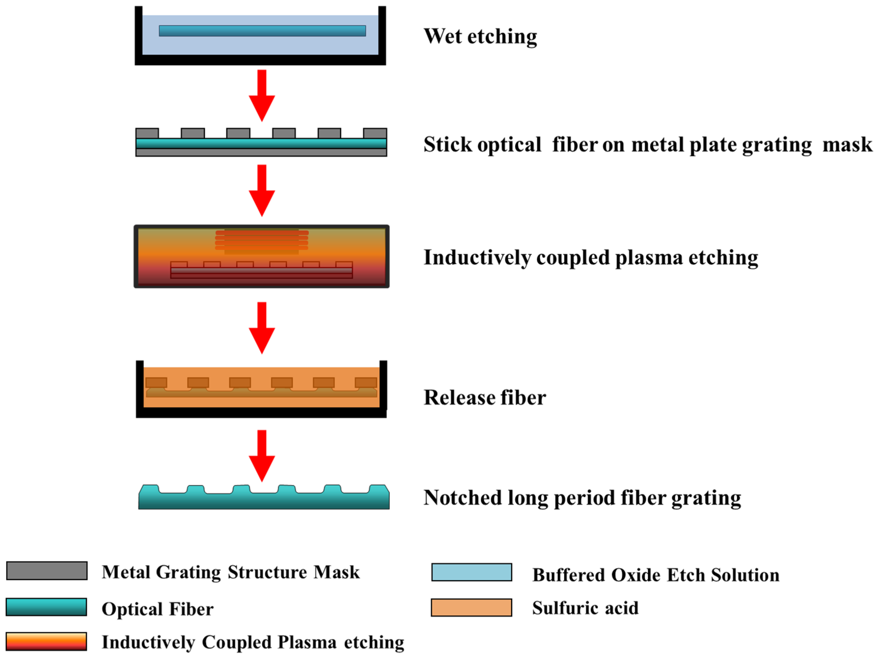
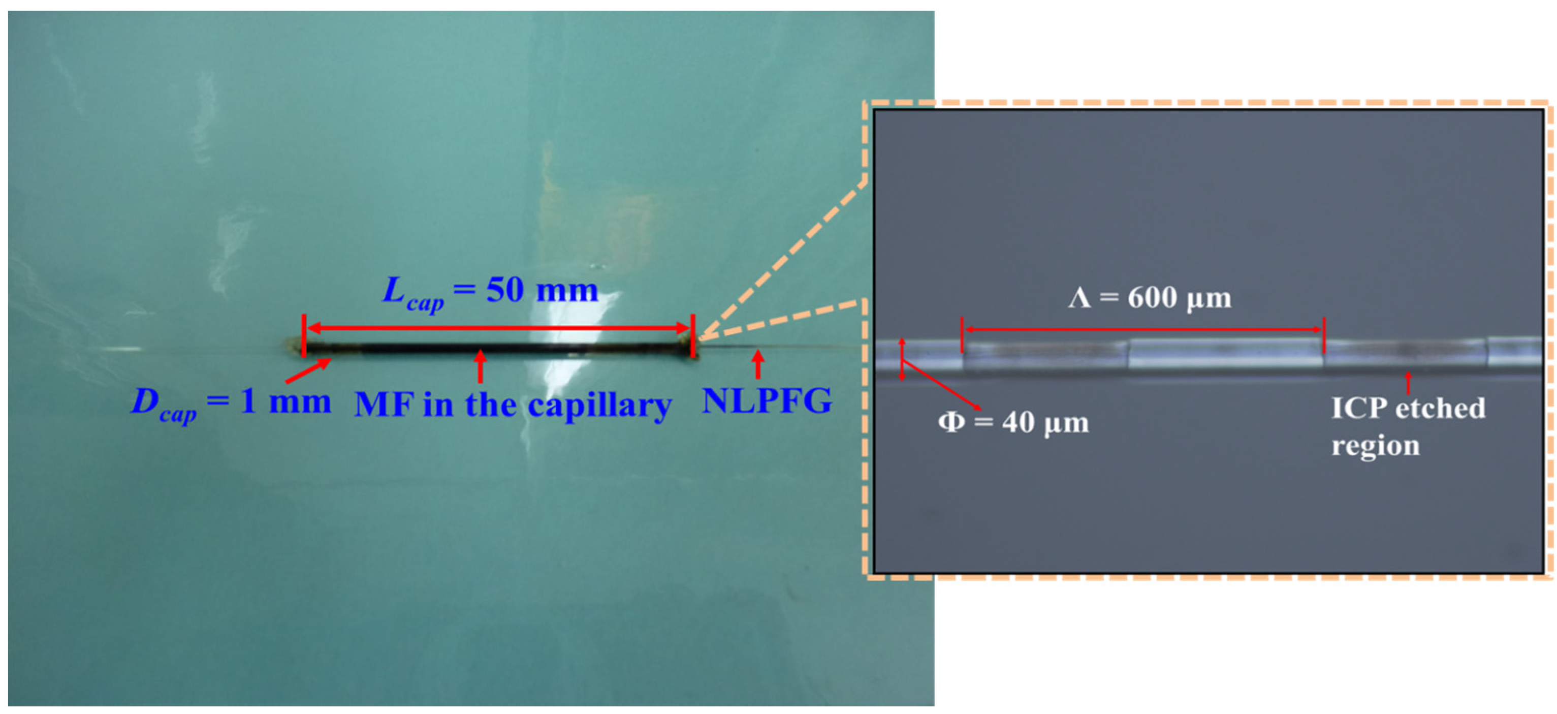
2.2. Process and Fabrication of the NLPFG

First, in order to diminish thicknesses of single-mode optical fibers, a buffered oxide etch (BOE) solution was used to etch fibers, which were attached to a plastic board. The fibers were then affixed to a metal plate grating mask, which was designed with periods of 590 μm, 600 μm, 610 μm, and 620 μm, by using high-temperature resistant adhesive. Subsequently, the ICP dry etching method was employed to yield surface notched periodic grating patterns and change the cladding dimensions onto the wet etched fibers to achieve grating resonant wavelength spectrum close to the vicinity of 1550 nm [25]. The ICP etching procedure used CF4 gas as the plasma ion reactive gas. The top substrate was set at 600 W, and the bottom substrate was set at 150 W. The surface notched period structure was etched on the etched fiber at an ICP etching rate of about 2.5 μm/min. Finally, the etched devices were released with acid solution to remove the high-temperature resistant adhesive on the fibers. The NLPFG was obtained after it was released from the metal mask. The production process is illustrated in Figure 1.
Figure 1. The schematic diagram of the manufacturing process of the notched long-period fiber grating (NLPFG).
Applsci 06 00009 g001

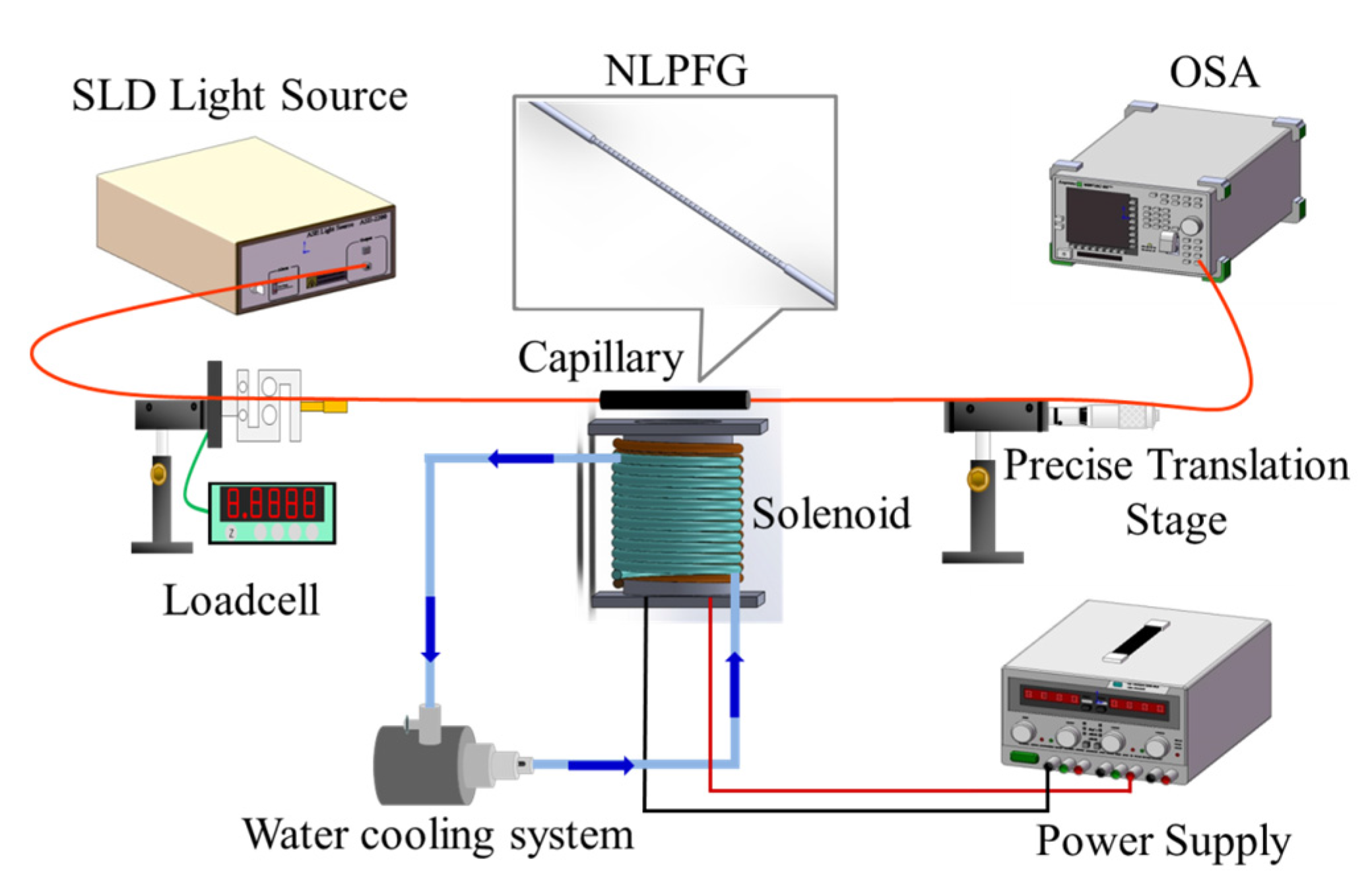
2.3. Experimental Setup for the NLPFG Magnetic Field Sensor

In this experiment, the NLPFG was fabricated by using the ICP technique on the single-mode fiber. Figure 2 shows an image of NLPFG magnetic field sensor filled with the magnetic fluid in a capillary and an optical microscopy (OM) photo of the segment of a NLPFG illustrates the relative dimensions. During this experiment, the grating period Λ of the NLPFG was 600 μm, the diameter Ф of the wet etched region was 40 μm, and the length of grating structures was 30 mm. We positioned the NLPFG into a capillary, where the length Lcap was 50 mm with an inner diameter Dcap of 1 mm, and then injected the MF into it. The both sides of the capillary were then sealed by epoxy to prevent the MF from evaporating and flowing out during the experiment. Fe3O4 water-based MF (EMG 605, Ferrotec.) was used in the experiment. This MF is a black-brown opaque liquid which contains 10 nm-diameter ferromagnetic nanoparticles, and the volume concentration is 3.9%. The density of this MF is 1.18 × 10³ kg/m3. Figure 3 exhibits a transmission electron microscopy (TEM) image of Fe3O4 iron oxide nanoparticles dispersed in a MF [26]. The refractive index of the EMG 605 MF is estimated to be about 1.40 ± 0.02 [15], lower than that of fiber silica cladding. When the external magnetic field strength is increased, the particles agglomerate to form columns or chains in the liquid in the direction of the magnetic field, which leads to phase separation between the particles and the carrier liquid [27,28]. In the specific MF, its refractive index is reduced with increasing magnetic field while its scattering loss increases. Accordingly, the cladding mode will be greatly confined into the thinned cylindrical area of the cladding, leading to lower overlap with the etched grating. While with the aforementioned refractive index modification mechanism of the MF, the contrast of the relief long-period grating will increase, and the MF scattering losses can also constructively contribute to the LPFG strength [22]. The negative refractive index changes induced with the increase of the magnetic field dominate over the other two effects, leading to a reduction of the LPFG notch strength.
Figure 2. The image of a NLPFG magnetic field sensor filled with magnetic fluid (MF) in a capillary and in-set optical microscopy (OM) photo detailing the dimensions of the grating section of the NLPFG.
Applsci 06 00009 g002
Figure 3. The transmission electron microscopy (TEM) image of iron oxide (Fe3O4) nanoparticles dispersed in a magnetic fluid [26].
Applsci 06 00009 g003
The experimental setup of the proposed sensor is shown in Figure 4. An electric solenoid was placed perpendicularly to the sensor, and the magnetic field strength could be controlled by the current generated by the power supply. As the power supply was adjusted, for every increase of 1 A in current, the magnetic field of the solenoid was increased by 8.67 mT. The current was exported by the power supply based on increments of 0.4 A, increasing from 0 A (0 mT) to 3.2 A (27.74 mT). To avoid the thermal effect, we employed a pump and copper tubes to construct a water cooling system that was used to keep the temperature of the electric solenoid steady. During the process of the experiment, we maintained the temperature variations within 1.5 °C. The NLPFG magnetic field sensor was connected to a super luminescent diode (SLD) broadband light source, a precise translation stage, a load cell, and an optical spectrum analyzer (OSA). Subsequently, the transmission spectra of the magnetic sensor were measured and recorded under distinct magnetic flux densities.
Figure 4. Schematic diagram of the experimental setup of the NLPFG magnetic field sensor with MF based on Fe3O4 nanoparticles.
Applsci 06 00009 g004

3. Results and Discussion

The NLPFG is a loss tunable filter based on periodic refractive index modulation caused by external loadings. When the NLPFG is placed under axial loading, it generates a periodic strain field owing to the expanded cross section area, which subsequently affects the refractive index periodic distribution of the optical fiber and produces an attenuated loss dip in the spectrum. Before we applied the external magnetic field to the NLPFG magnetic field sensor, we first gave the sensor some fixed loadings on the platforms, which were used to firmly hold the fibers straight, in order to have the center wavelength of the attenuation band be 1540.78 nm and the dip of the transmission loss be −19.41 dB. The optical transmission characteristics, included absorption and scattering effect, of MF under the application of magnetic fields have been demonstrated [29,30]. The behavior of induced loss of the NLPFG magnetic sensor within the ferrofluid is related to magnetic field stimulus. The spectra between the magnetic flux density and the resonant wavelength of the attenuation band loss are shown in Figure 5. As the applied magnetic flux density was gradually increased from 0 mT to 27.74 mT, the transmission loss was increased from −19.41 to −15.93 dB and the variations of loss in the spectra were about 3.48 dB. Figure 6 presents the relationship between the magnetic flux density and the dip of the transmission loss. We can see that the dip of the transmission loss was increased as the magnetic flux density was increased, which can be fitted well by a Langevin function with a R2 value of 0.9983. The curve can be used to calibrate the nonlinearity between the transmission loss and magnetic flux density during the modulation. The sensitivity was 0.125 dB/mT. That sensitivity was compared, in turn, with the magnetic field sensitivity of the magnetic field sensors developed by Ting Liu et al. [14] and Lei Gao et al. [17], which were reported to be 0.0382 dB/mT and −0.1233 dB/mT, respectively. The magnetic field sensitivity of the NLPFG based on the ferromagnetic fluid presented in this paper was higher than the sensitivities of those other sensors.
Figure 5. The spectra of the NLPFG magnetic field sensor under different magnetic flux densities for magnetic field sensing.
Applsci 06 00009 g005
Figure 6. The relationship of the transmission loss for the NLPFG magnetic field sensor under distinct magnetic flux densities.
Applsci 06 00009 g006

4. Conclusions

In conclusion, this paper demonstrated the manufacturing process of an NLPFG magnetic field sensor utilizing MF as the sensing material. The results depict the feasibility of our proposed NLPFG magnetic field sensor based on ferromagnetic fluid containing nanoparticles. In addition to being used as a magnetic sensor, the proposed NLPFG sensing structure can be used as a current sensor as well. When the applied external magnetic flux density increases to 27.74 mT, the transmission loss variation of the dip resonant wavelength is 3.48 dB. The sensitivity of the sensor is nearly 0.125 dB/mT. The sensor also has the advantages of a low-cost fabrication procedure and suitability for mass production.

Acknowledgments

This work was supported by the Ministry of Science and Technology, Taiwan (grant number MOST 103-2221-E-151-009-MY3).

Author Contributions

Chia-Chin Chiang designed methods of experiment and analyzed the data. Sheng-Feng Wang performed experimental works, analyzed the experimental data and wrote the paper.

Conflicts of Interest

The authors declare no conflict of interest.

References

  1. Lenz, J.E. A review of magnetic sensors. Proc. IEEE 1990, 78, 973–989. [Google Scholar] [CrossRef]
  2. Kersey, A.D.; Davis, M.A.; Patrick, H.J.; LeBlanc, M.; Koo, K.; Askins, C.; Putnam, M.A.; Friebele, E.J. Fiber grating sensors. J. Lightwave Technol. 1997, 15, 1442–1463. [Google Scholar] [CrossRef]
  3. Wu, J.Z.; Chao, J.C.; Hu, J.Y.; Chiang, C.C. Fabrication of the Long Bragg Grating by Excimer Laser Micro Machining with High-Precision Positioning XXY Platform. Smart Sci. 2014, 2, 20–23. [Google Scholar]
  4. Bhatia, V.; Vengsarkar, A.M. Optical fiber long-period grating sensors. Opt. Lett. 1996, 21, 692–694. [Google Scholar] [CrossRef] [PubMed]
  5. Vengsarkar, A.M.; Lemaire, P.J.; Judkins, J.B.; Bhatia, V.; Erdogan, T.; Sipe, J.E. Long-period fiber gratings as band-rejection filters. J. Lightwave Technol. 1996, 14, 58–65. [Google Scholar] [CrossRef]
  6. James, S.W.; Tatam, R.P. Optical fibre long-period grating sensors: Characteristics and application. Meas. Sci. Technol. 2003, 14, R49–R61. [Google Scholar] [CrossRef]
  7. Harumoto, M.; Shigehara, M.; Suganuma, H. Gain-Flattening Filter Using Long-Period Fiber Gratings. J. Lightwave Technol. 2002, 20. [Google Scholar] [CrossRef]
  8. Vaziri, M.; Chin-Lin, C. Etched fibers as strain gauges. J. Lightwave Technol. 1992, 10, 836–841. [Google Scholar] [CrossRef]
  9. Wang, Y.P.; Xiao, L.; Wang, D.N.; Jin, W. Highly sensitive long-period fiber-grating strain sensor with low temperature sensitivity. Opt. Lett. 2006, 31, 3414–3416. [Google Scholar] [CrossRef] [PubMed]
  10. Wei, X.; Wei, T.; Li, J.; Lan, X.; Xiao, H.; Lin, Y.S. Strontium cobaltite coated optical sensors for high temperature carbon dioxide detection. Sens. Actuators B Chem. 2010, 144, 260–266. [Google Scholar] [CrossRef]
  11. Yokouchi, T.; Suzaki, Y.; Nakagawa, K.; Yamauchi, M.; Kimura, M.; Mizutani, Y.; Kimura, S.; Ejima, S. Thermal tuning of mechanically induced long-period fiber grating. Appl. Opt. 2005, 44, 5024–5028. [Google Scholar] [CrossRef] [PubMed]
  12. Yang, J.; Yang, L.; Xu, C.Q.; Xu, C.; Huang, W.; Li, Y. Long-period grating refractive index sensor with a modified cladding structure for large operational range and high sensitivity. Appl. Opt. 2006, 45, 6142–6147. [Google Scholar] [CrossRef] [PubMed]
  13. Falate, R.; Frazão, O.; Rego, G.; Fabris, J.L.; Santos, J.L. Refractometric sensor based on a phase-shifted long-period fiber grating. Appl. Opt. 2006, 45, 5066–5072. [Google Scholar] [CrossRef] [PubMed]
  14. Liu, T.; Chen, X.; Di, Z.; Zhang, J.; Li, X.; Chen, J. Tunable magneto-optical wavelength filter of long-period fiber grating with magnetic fluids. Appl. Phys. Lett. 2007, 91, 121116:1–121116:3. [Google Scholar] [CrossRef]
  15. Konstantaki, M.; Candiani, A.; Pissadakis, S. Optical fibre long period grating spectral actuators utilizing ferrofluids as outclading overlayers. J. Eur. Opt. Soc.-Rapid Publ. 2011, 6. [Google Scholar] [CrossRef]
  16. Childs, P.; Candiani, A.; Pissadakis, S. Optical fiber cladding ring magnetic field sensor. IEEE Photonics Technol. Lett. 2011, 23, 929–931. [Google Scholar] [CrossRef]
  17. Gao, L.; Zhu, T.; Deng, M.; Chiang, K.S.; Sun, X.; Dong, X.; Hou, Y. Long-period fiber grating within -shaped fiber using magnetic fluid for magnetic-field detection. Photonics J. IEEE 2012, 4, 2095–2104. [Google Scholar]
  18. Zheng, Y.; Dong, X.; Chan, C.C.; Shum, P.P.; Su, H. Optical fiber magnetic field sensor based on magnetic fluid and microfiber mode interferometer. Opt. Commun. 2015, 336, 5–8. [Google Scholar] [CrossRef]
  19. Zhang, N.M.Y.; Dong, X.; Shum, P.P.; Hu, D.J.J.; Su, H.; Lew, W.S.; Wei, L. Magnetic field sensor based on magnetic-fluid-coated long-period fiber grating. J. Opt. 2015, 17. [Google Scholar] [CrossRef]
  20. Yang, S.Y.; Chieh, J.J.; Horng, H.E.; Hong, C.Y.; Yang, H.C. Origin and applications of magnetically tunable refractive indexof magnetic fluid films. Appl. Phys. Lett. 2004, 84, 5204–5206. [Google Scholar] [CrossRef]
  21. Chan, C.C.; Lew, W.S.; Jin, Y.; Liew, H.F.; Chen, L.H.; Wong, W.C.; Dong, X. High Extinction Ratio Magneto-Optical Fiber Modulator Based on Nanoparticle Magnetic Fluids. Photonics J. IEEE 2012, 4, 1140–1146. [Google Scholar]
  22. Daxhelet, X.; Kulishov, M. Theory and practice of long-period gratings: When a loss becomes a gain. Opt. Lett. 2003, 28, 686–688. [Google Scholar] [CrossRef] [PubMed]
  23. Lin, C.Y.; Wang, L.A.; Chern, G.W. Corrugated long-period fiber gratings as strain, torsion, and bending sensors. J. Lightwave Technol. 2001, 19. [Google Scholar] [CrossRef]
  24. Erdogan, T. Fiber grating spectra. J. Lightwave Technol. 1997, 15, 1277–1294. [Google Scholar] [CrossRef]
  25. Vasiliev, S.; Varelas, D.; Limberger, H.; Dianov, E.; Salathe, R. Postfabrication resonance peak positioning of long-period cladding-mode-coupled gratings. Opt. Lett. 1996, 21, 1830–1832. [Google Scholar] [CrossRef] [PubMed]
  26. Rinaldi, C.; Franklin, T.; Zahn, M.; Cader, T. Magnetic Nanoparticles in Fluid Suspension: Ferrofluid Applications; Taylor & Francis: Abingdon, UK, 2004. [Google Scholar]
  27. Horng, H.E.; Hong, C.Y.; Yang, S.Y.; Yang, H.C. Designing the refractive indices by using magnetic fluids. Appl. Phys. Lett. 2003, 82, 2434–2436. [Google Scholar] [CrossRef]
  28. Hong, C.Y.; Jang, I.J.; Horng, H.E.; Hsu, C.J.; Yao, Y.D.; Yang, H.C. Ordered structures in Fe3O4 kerosene-based ferrofluids. J. Appl. Phys. 1997, 81, 4275–4277. [Google Scholar] [CrossRef]
  29. Rikken, G.; van Tiggelen, B. Observation of magnetically induced transverse diffusion of light. Nature 1996, 381, 54–55. [Google Scholar] [CrossRef]
  30. Candiani, A.; Argyros, A.; Leon-Saval, S.; Lwin, R.; Selleri, S.; Pissadakis, S. A loss-based, magnetic field sensor implemented in a ferrofluid infiltrated microstructured polymer optical fiber. Appl. Phys. Lett. 2014, 104. [Google Scholar] [CrossRef]

