Article

Tests and Analysis of the Compressive Performance of an Integrated Masonry Structure of a Brick-Stem-Insulating Layer

1
College of Architecture and Civil Engineering, Beijing University of Technology, No. 100, Pingleyuan, Chaoyang District, Beijing 100124, China
2
University of Architectural Engineering, North China University of science and technology, No. 46, Xinghua West street, Tangshan 063009, China
3
Institute of engineering mechanics, China Earthquake Administration, The North Ring Road, YanjiaoDistrict, Langfang 150080, China
4
Academy of Railway Sciences, Scientific & Technological Information Research Institute, No. 2 Daliushu Road, Haidian District, Beijing 100081, China
*
Author to whom correspondence should be addressed.
Submission received: 29 February 2016 / Revised: 27 April 2016 / Accepted: 6 May 2016 / Published: 11 May 2016

Abstract

:
This paper proposes, for low buildings, an integrated wall structure of a brick-stem-insulating layer, which plays a major part in both heat preservation and force bearing. The research team has tested the thermal performance of the structure, the results of which are satisfying. To further study the force-bearing performance, the paper carries out compressive tests of specimens of different structural design, with two types of bricks, i.e., clay and recycled concrete bricks; three types of stems, i.e., square-shaped wood, square-shaped steel pipe and circular steel pipe; and one type of insulating layer, i.e., fly ash masonry blocks. Afterward, the force bearing performance, damage that occurred, compressive deformation and ductility of all of the specimens are compared. On the sideline, the structure is applied in the construction of a pilot residence project, yielding favorable outcomes. The results indicate that in comparison with a brick wall with an insulating layer sandwiched in between, the integrated wall structure of bricks and fly ash blocks is a more preferable choice in terms of compressive performance and ductility. The integrated wall structure of brick-stem-fly ash blocks delivers much better performance to this end. Note that regarding the stem’s contribution to compressive strength, circular steel pipe is highest, followed by square-shaped steel pipe and then square-shaped wood. The compressive performance of the sandwiched blocks surpasses that of the two brick wall pieces combined by a large margin.

1. Introduction

When studying the force-bearing performance of low buildings in villages and small towns, researchers have attained fruitful results, which can be roughly categorized into three schools [1,2,3,4,5]. Developed countries, such as the United States and Japan, take the lead in the first category, as they have developed a well-designed standard system for seismic resistance. Related tasks—the issuance of compulsory regulations, the release of earthquake insurance and tax collection—fall under the jurisdiction of each country directly. Some European countries have drawn on the seismic research at hand and have carried out the analysis of structural resistance against progressive collapse and the standard of design. Some Latin American countries, such as Peru and Costa Rica, make up the second school. Constantly plagued by earthquakes, these countries have put anti-seismic tasks at the top of their agenda. In line with the local culture, the geological environment on the ground and the economic reality, they have worked actively to study seismic technology; simultaneously, they encourage people to improve the seismic performance of their houses by leveraging government subsides, e.g., a host of enhancement technology research programs for adobes have been carried out to theoretically underpin the work of seismic safety in rural areas. Countries of the third school, located in Asia and Africa, though constantly plagued by earthquakes, have yet to grow the economic muscle to carry out large-scale disaster prevention efforts. In India, for example, 70% of its buildings have poor seismic resistance. Although the government unveiled a public policy of disaster alleviation-working to improve quake-proof capacity via supportive measures in the 1990s, the campaign turned out to be a disappointment due to poor management. Considering the economic difficulties of countries like Nepal, the international community has lent a helping hand, and the recipient countries have encouraged researchers to enhance the seismic performance of local residences; however, the outcomes largely stay at the theoretical level. Some North African countries, such as Algeria and Morocco, have yet to register visible progress in the nationwide application of seismic enhancement measures, though the relevant works have been included in the government agenda. By and large, most of the developing countries—due to economic difficulties—have yet to launch a regulatory and managerial yardstick for rural housing, which explains the limited progress in seismic technology and the poor seismic resistance of most rural buildings. Without technological backup, these countries will be trapped in a vicious cycle in the long run.
In response to the climbing temperature worldwide, all countries have committed to boosting the development of their low-carbon industries in their own way. Under such background, the architecture field works to contribute its due share in this all-out endeavor. With this vision of low carbon and environmental protection, the world has experienced a transition from the traditional clay-brick masonry structure to a newly developed masonry design, the mechanical performance of which has become the R & D focus of researchers in this field.
Yoshimura and his team studied the influence of the height–width ratio on the shear strength of a concrete-block wall. The results indicated that strong structural columns evidently help to improve the shear stress of the wall [6]. Tomazevic, on the other hand, worked with his team to experimentally study 32 pieces of a reinforced block wall, exploring the influence of different loading approaches on the bearing performance of the overall wall structure. Their findings showed that the increase in compressive strain in the vertical direction drives up the shear stress of the wall while simultaneously bringing down the deformative capacity of the structure [7]. In comparison, Riddington and Ghazali worked out the failure mechanism of the masonry wall structure under shear loading and analyzed the influence of stress changes in the vertical direction on the shear strength of the wall [8]. Hamid and Lotfi put a full-scale masonry wall of grouted concrete under vertical stress and imposed loading from the side. They believed that as the longitudinal re-bar(s) yields, vertical loading has a small part to play in terms of displacement limit change at the top [9]. Banting and Dakhakhni carried out experimental studies on the seismic performance of a reinforced masonry block wall with a constraint design. They noticed that the constraint structure helps to mitigate the cracking, which in turn enhances the seismic resistance of the wall [10].
Shedid et al. performed cyclic dynamic tests on three pieces of reinforced block shear wall with different height-to-length ratios and various reinforcement ratios. By doing so, they noticed that the specimen promises fairly good performance with respect to energy consumption; at the same time, a greater reinforcement ratio in the vertical direction helps to undermine stiffness degradation and build up the deformative capacity of the structure [11]. In a comparative study of the exterior insulation of different wall structures, i.e., concrete blocks, cement blocks, bricks, etc., Oak Ridge National Laboratory noticed that the concrete-block specimen excels in this category [12]. Yang and Zhang focused on the influence of eccentricity on the force-bearing performance of a masonry structure with autoclaved fly-ash bricks. Their works showed that the force-bearing performance linearly declines with increasing eccentricity [13]. The experimental research on the compressive resistance of the masonry structure with recycled-concrete bricks, carried out by Liu showed that compared with its clay-brick counterpart, the structure falls short with respect to force-bearing performance and its compressive strength deteriorates in a fairly quick manner. However, note that greater mortar strength drives up the force-bearing and deformative capacities of the structure [14]. Zheng et al. considered the seismic performance of a low masonry structure constraint by using stem-type structural columns as the focus and determined that the columns, compared with their cast-in-situ counterparts, contribute to better seismic resistance of the overall masonry structure [15]. With the help of a vibration test rig, Lidija et al. managed to test the masonry-steel frame wall structure used in the Beauharnois Generating Station in Montreal, Canada. The results indicated that the interaction between the steel frame and wall is a cooperative one, as major vibration only results in local cracks and some displacement at the joint of the brick wall and the steel frame [16].
Therefore, it can be said that the research endeavors in this field, that is, the basic mechanical performance of wall structures, mainly focus on the study of those made of one single wall material or the integration of different materials; however, the mechanical performance of the integrated wall structure that embodies both thermal insulation and force bearing seems to be overlooked. In other words, it is the major concern and pressing challenge of researchers and engineers at large to put forward wall structures and resource-efficient housing designs to fill in this gap.
This paper, giving full consideration to the wall structure and the material applied, proposes an integrated wall structure of a brick-stem-insulating layer, with the wall being the member for both thermal insulation and force bearing. The structure opens up new dimensions in the following fields: (1) The manufacture of recycled bricks and fly ash blocks facilitates the green effort, as construction and industrial wastes are recycled for the preparation of recycled concrete aggregate and fly ash. (2) With the lightweight fly ash blocks sandwiched in between, the integrated structure, compared with a brick wall of the same thickness, shows great improvement in thermal performance and ductility. Note that the compressive performance of the sandwiched blocks surpasses that of the two brick wall pieces combined by a large margin. (3) The steel pipe embedded largely drives up the compressive performance and the ductility of the structure.
Study of the heat transfer coefficient of the integrated wall structure of bricks and fly ash masonry blocks has led to the following conclusion: the coefficients measured for the four types of structure, i.e., clay-brick wall, clay-brick wall with fly ash masonry blocks sandwiched in between as an insulating layer, recycled-brick wall, and recycled-brick wall with fly ash masonry blocks sandwiched as an insulating layer, are 1.607, 0.782, 2.046 and 0.812, respectively. Therefore, it can be said that with the help of the fly-ash-block layer, the integrated structures—of either clay bricks or recycled bricks—promise better thermal performance compared with brick structures, where only one type of material is involved [17].
To further study the force-bearing performance, this paper carries out compressive tests of specimens of different structural design, with two types of bricks, i.e., clay and recycled concrete bricks; three types of stems, i.e., square-shaped wood, square-shaped steel pipe and circular steel pipe; and one type of insulating layer, i.e., fly ash masonry blocks. Afterward, the force bearing performance, damage that occurred, compressive deformation and ductility of all of the specimens are compared.

2. Experiment Overview

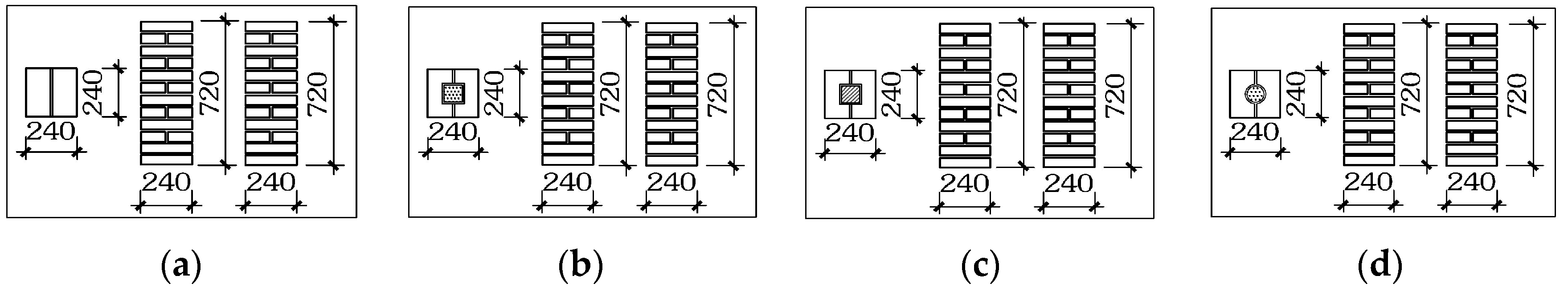
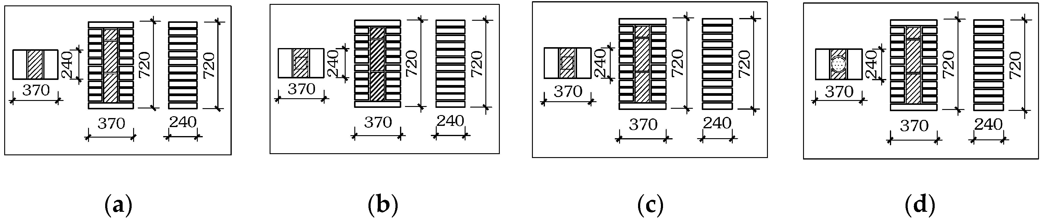
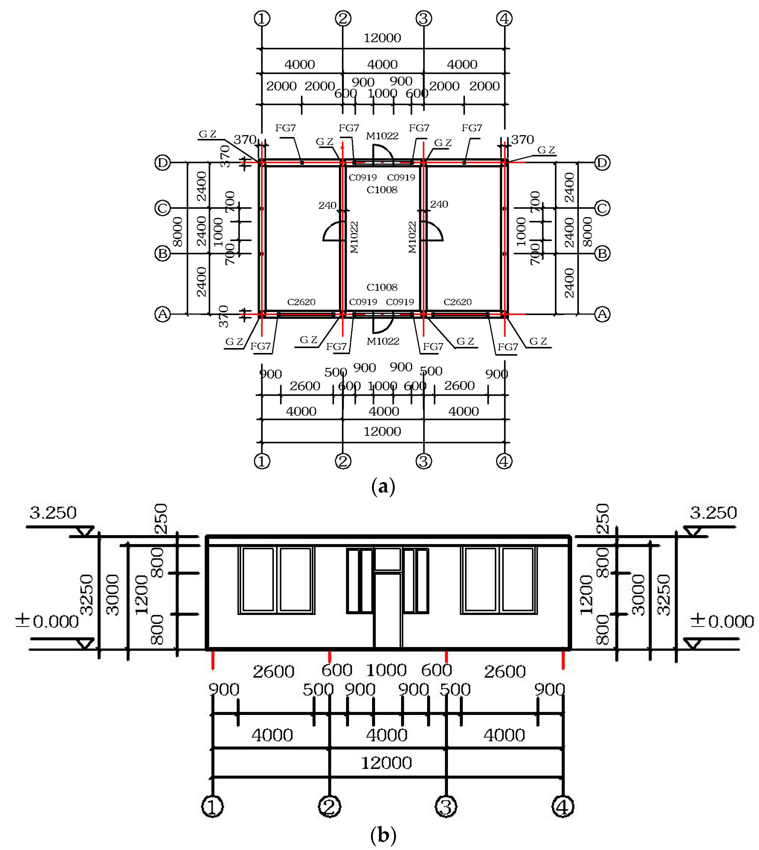
2.1. Experiment Design

The 16 integrated masonry pieces of the brick-stem-insulating layer are evenly divided into 4 groups, with the first group being specimens of clay bricks (FCB1–FCB4); the second group, specimens of recycled concrete bricks (RCB1–RCB4); the third group, specimens of clay bricks and fly ash blocks (AFCB1–AFCB4); and the fourth group, specimens of recycled concrete bricks and fly ash blocks (ARCB1–ARCB4). Figure 1 shows the specimen layout with a 240 mm × 240 mm cross section, while Figure 2 shows the specimen layout with a 240 mm × 370 mm cross section. Please refer to Table 1 for the structural details and specifications of the specimens.

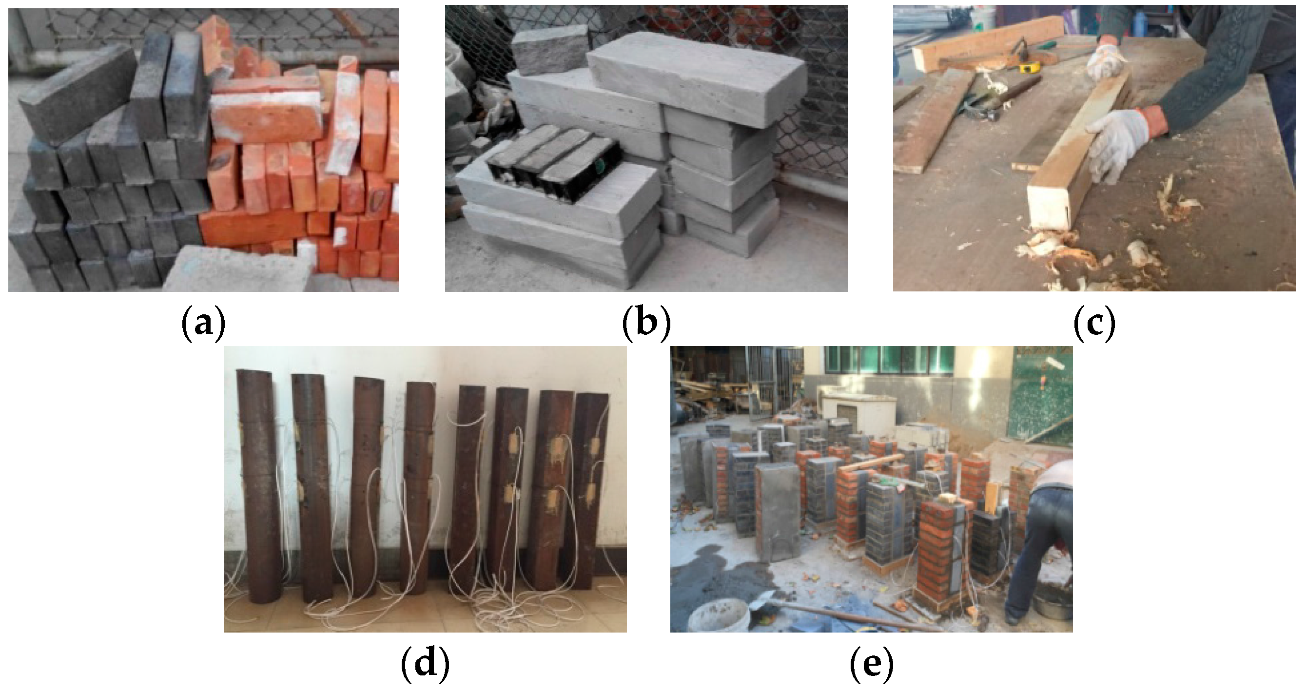
2.2. Making of Specimens

Please refer to Figure 3 regarding how the clay bricks, recycled-concrete bricks, fly-ash blocks, recycled concrete, square-shaped wood stem, lightweight concrete-filled steel stem, integrated masonry parts, etc., were made.

2.3. Mechanical Performance of the Materials

Please see Table 2 for the mechanical performances of the materials measured.

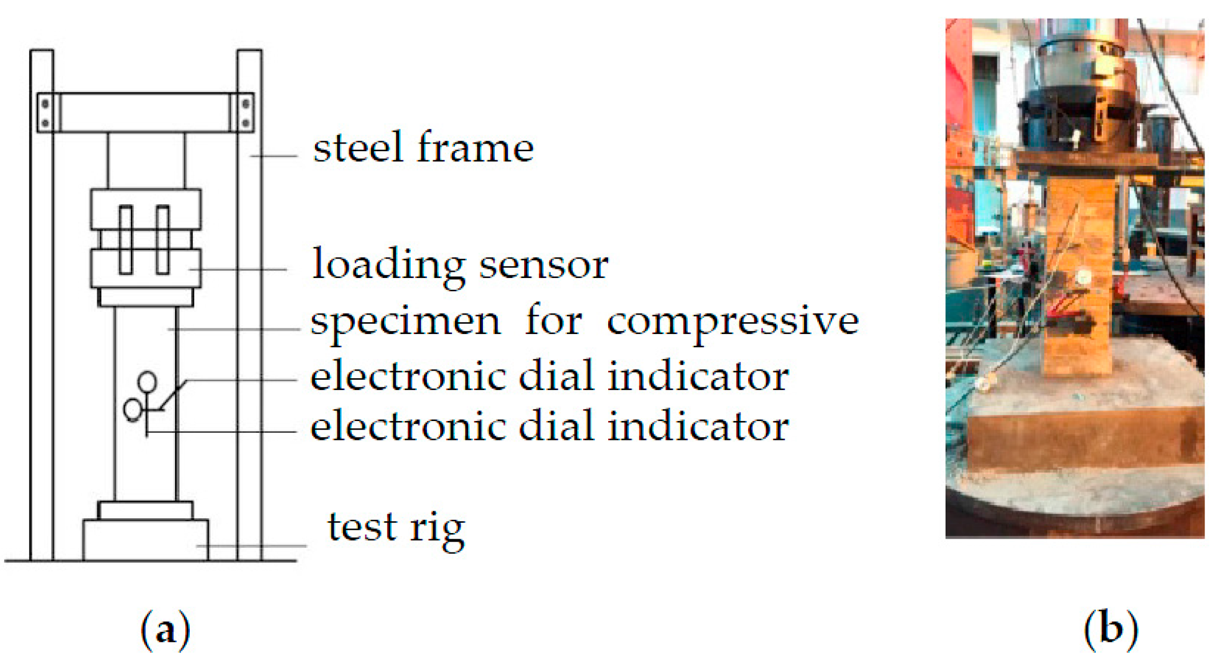
2.4. Loading Imposed

The test takes a loading controlled approach, where monotone loading is imposed by grades, with the loading in each grade being 1/10 of the loading limit expected. In carrying out the test, the duration for each grade lasts for 2 to 3 min, where the cracking of the specimen is closely followed. As the deformation reaches a steady stage, the loading imposed and the displacement that occurs are recorded before the test moves on to the next grade of loading. When the loading imposed hits 60% of the loading limit (or fu), the loading increment shall be adjusted to 1/15–1/20 of the expected limit. As the loading comes to the limit, the increment shall be further adjusted (lowered) in which continuous loading shall be imposed slowly. Please refer to Figure 4a,b for the loading device applied and photo of the test site.
Test Items: loading (measured by loading sensor); strain of square-shaped wood, square-shaped steel pipe and circular steel pipe (measured by the attached strain gauges); and relative displacement in axial and horizontal directions within gauge length (measured by electronic dial indicator).

3. Results and Analysis

3.1. Failure Process

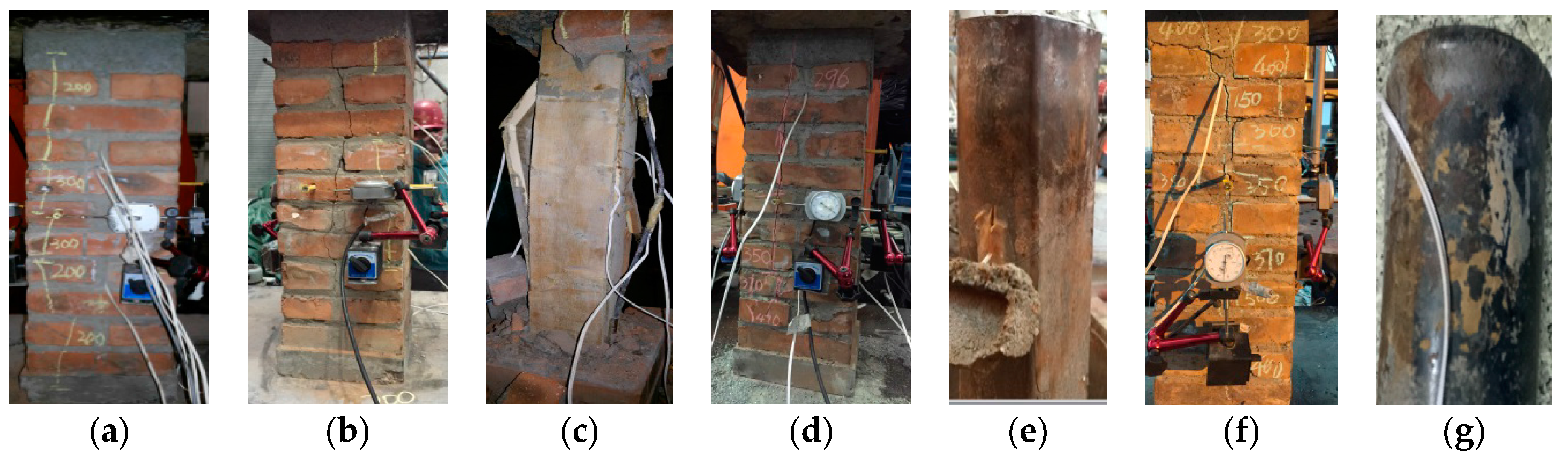
3.1.1. Group One (FCB1–FCB4)

(1) FCB1: As the loading starts, no visible crack is noticed at the surface and the loading-displacement curve develops in a linear manner, during which the specimen reaches the elastic stage. Under a loading of 150 kN, the top part of the specimen starts to crack slightly and vertically. The increase in loading encourages the cracks to further develop along the mortar joint. At this point, the axial and longitudinal deformations take place at an accelerated pace, meaning that the structure has entered the elastic-plastic stage. As the loading tops 200 kN, cracks cross through the specimen along the direction of the mortar joint in the middle and expand in width, accompanied by a minor cracking sound and evident exfoliation. Under a loading of 251 kN, the bearing performance of the specimen declines drastically, resulting in its utter failure. Please refer to Figure 5a for the state of the specimen upon failure.
(2) FCB2: Like FCB1, FCB2 starts with the elastic stage, then enters the elastic-plastic stage and ends with the failure stage. The difference lies in the split limit, regarding which FCB2 stands out because its split limit tops 150 kN. As the loading imposed hits 300 kN, the exterior clay starts to exfoliate slightly. Under approximately 330 kN, the specimen crashes, while the loading–displacement curve declines. At this point, the crashed square wood stem indicates that it works with the clay bricks in tandem to bear the force imposed and promises fairly good results. Please see Figure 5b for the specimen state at the failure stage and Figure 5c for the bent stem.
(3) FCB3: As the elastic stage, FCB3 bears resemblance to its counterpart FCB1. Under a loading of 430 kN, the first crack appears vertically and slightly some distance from the central line of the wall’s elevation. As the loading increases, cracks—both vertical and longitudinal—are noticed at other sides, which, though minor, are slowly extending. When the loading further increases to 550 kN, the vertical and longitudinal deformations take place at an accelerated pace, while the cracks expand at both ends and cross through the bricks. As the loading tops 670 kN, through cracks are noticed along the mortar joint. Therefore, the loading pace is slowed down; however, the clay bricks start to exfoliate. Upon a loading of 830 kN (the compressive strength of the square-shaped pipe measured stands at 767 kN), the clay bricks crash, while the loading-displacement curve starts to decline. At this point, the specimen is destroyed, with minor buckling observed at both ends of the concrete-filled steel stem. Please refer to Figure 5d for the specimen state at the failure stage and Figure 5e for the state of the square-shaped concrete-filled steel stem upon specimen failure.
(4) FCB4: The damage process of FCB4 generally follows the same pattern of FCB3, with the split limit as an exception, which exceeds that of FCB3. As the loading reaches 530 kN, the first crack—minor and vertical—is noticed at the top part of the specimen near the central line. The increase in loading causes a growing number of slight cracks, which develop at a slow pace. Under a loading of 660 kN, the vertical and longitudinal deformations increase, accompanied by the extension of cracks. As the loading further increases to 755 kN, through cracks are noticed along the mortar joint. At this stage, the loading starts to be imposed slowly, upon which cracks expand in width and exfoliation takes place at the clay bricks. The specimen crashes at a loading of 945 kN. At this point, the loading-displacement curve declines drastically, and the circular concrete-filled steel pipe starts to exfoliate and buckle at both ends. Please refer to Figure 5f for the failure state of the specimen and Figure 5g for that of the circular concrete-filled steel stem.

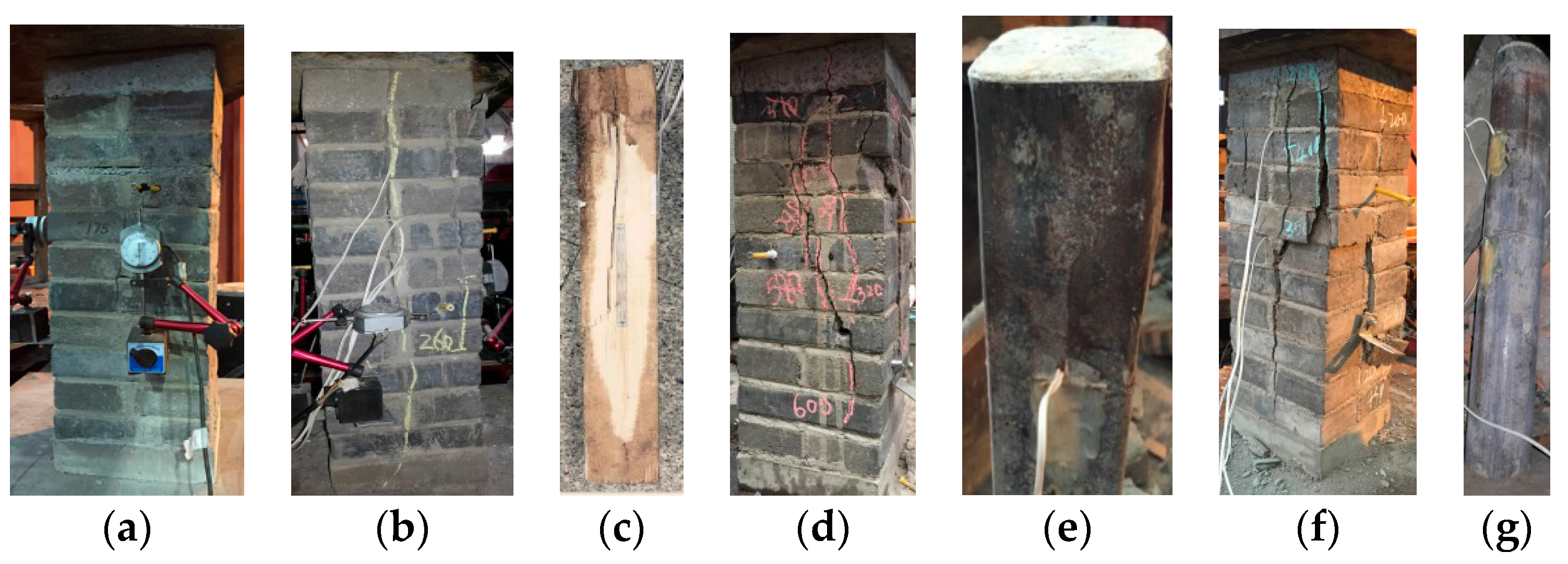
3.1.2. Group Two (RCB1–RCB4)

The failure process of group two roughly follows the same pattern as that of group one. However, compared with the specimen of clay bricks, recycled concrete bricks promise less cracks, though the cracking takes place at a faster pace. As the specimen reaches the failure stage, it breaks into pieces. Please see Figure 6a for the failure state of RCB1. RCB2 (with square-shaped wood stem embedded), with better compressive performance, experiences a slowdown in crack expansion. Again, the loading-displacement curve gradually declines before the specimen yields, which to some level indicates a delay of any impediment that may happen. At the final stage, through cracks are noticed near the central line of the side face along the mortar joint. Please refer to Figure 6b for the failure state of the specimen and Figure 6c for the failure of the square-shaped wood stem. Just as the steel-pipe reinforced clay brick specimen, the square-shaped (or circular) steel pipe embedded delays any impediment that may happen to the recycled concrete specimen. As a result, the split limit and the loading limit increase by a large margin. Please see Figure 6d–g for the failure states of the specimens and that of the steel pipe.

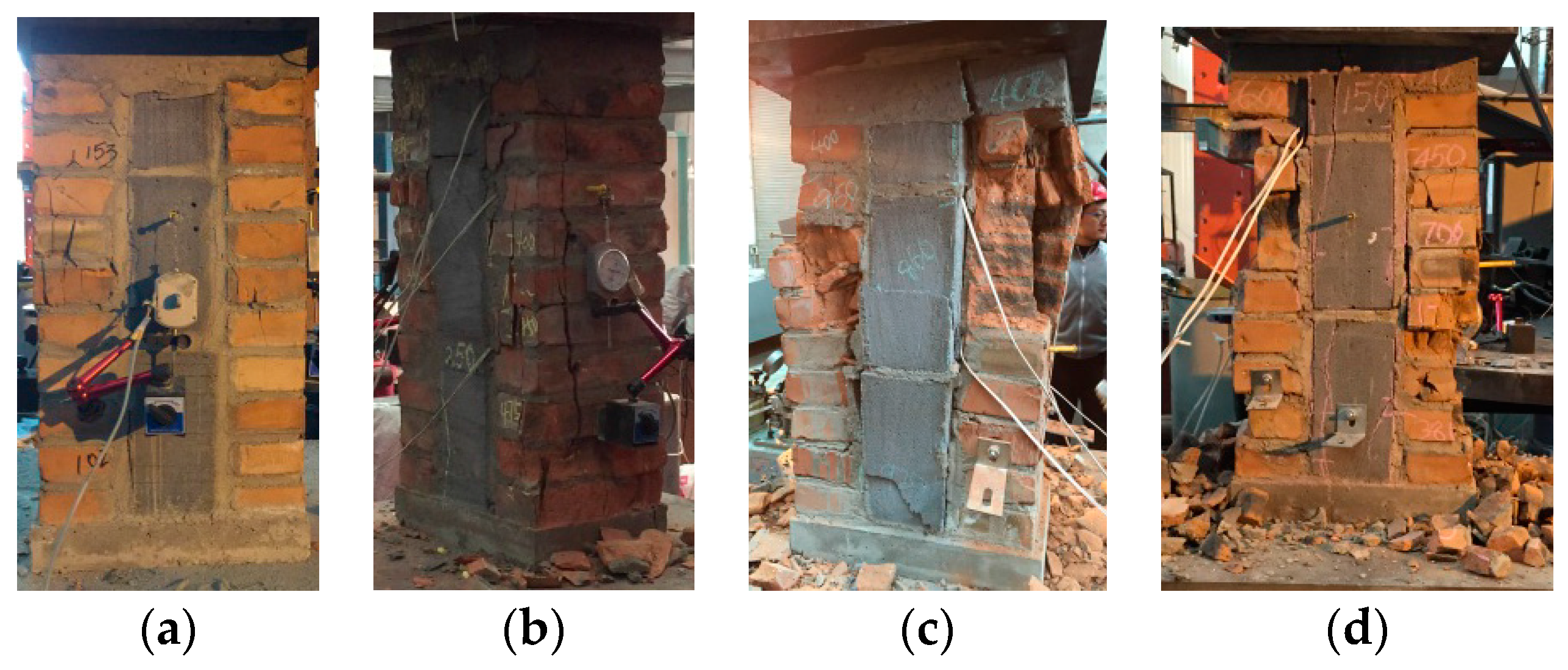
3.1.3. Group Three (AFCB1–AFCB4)

(1) AFCB1: As the loading remains at a relatively low level, nothing visible is noticed. When it reaches 175 kN, the joints of fly-ash blocks and clay bricks in the center start to crack vertically and then gradually extend at both ends as the loading increases to 200 kN. At this point, the clay bricks crack slightly, while the fly-ash blocks show no visible change. Under a loading of 250 kN, through cracks are noticed at the brick-block joints. As the ends of the vertical cracks on the clay bricks meet, some bricks crash. Afterward, the loading continues, during which exfoliation takes place; cracks at the top and bottom parts of the structure are widened and the fly ash blocks break in half. As the loading increases to 298 kN, the clay bricks at both sides of the fly ash blocks start to show wearing of the edges and corners, the clay bricks nearly crash and the blocks bend. Therefore, the specimen yields. Please refer to Figure 7a for the failure state of AFCB1.
(2) AFCB2: Apart from the improvement in split limit, loading limit and ductility, the failure process of AFCB2 bears resemblance to that of AFCB1.
(3) In comparison with AFCB2, AFCB3 and AFCB4 show great improvement in ductility, split limit and loading limit, as the cracks now densely spread on the surface. It can be said that the steel pipe embedded largely contributes to better force-bearing performance of the integrated brick-block masonry structure. Please see Figure 7c,d for the failure states of AFCB3 and AFCB4.

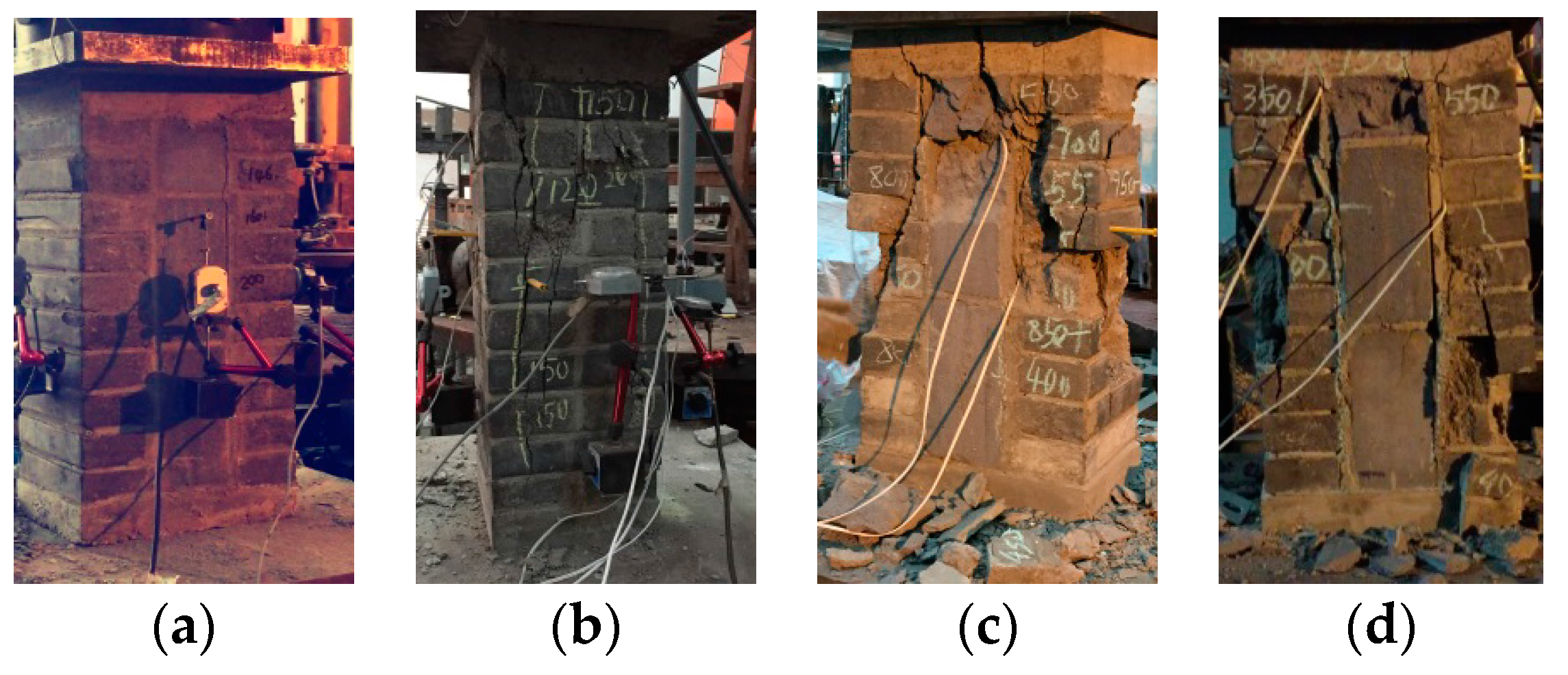
3.1.4. Group Four (ARCB1–ARCB 4)

For this group of specimens, the failure process proceeds in the same manner as that of group three. However, the integrated masonry structure of recycled concrete bricks and fly ash block shows more evident signs of brittle fractures in comparison. The cracks that appear, though decreased in quantity (compared with the specimens in group three), develop at a quickened pace. Upon failure, the structure breaks down into different pieces and the blocks exfoliate partially. Please see Figure 8a for the failure process of ARCB1. The paper notes regarding the subsequent tests that ARCB2, ARCB3 and ARCB4 deliver better ductility, split limit and loading limit compared with their counterpart ARCB1. Please see Figure 8b–d for the failure states of the specimens mentioned above.
The following can be concluded from Figure 5 to Figure 8: (1) The clay-brick wall, the recycled-concrete-brick wall, the integrated wall of clay bricks and fly ash blocks, and the integrated wall of recycled concrete bricks and fly ash blocks deliver a similar failure process, which shows classic signs of brittle fractures. (2) The stems embedded-square-shaped wood, square-shaped steel pipe and circular steel pipe visibly improve a structure’s split limit and loading limit. In other words, the integrated structures now deliver much better compressive performance. (3) The fly ash masonry blocks and bricks (clay bricks/recycled bricks) that are bonded by mortar are able to coordinate in a productive manner.

3.2. Analysis of Bearing Performance

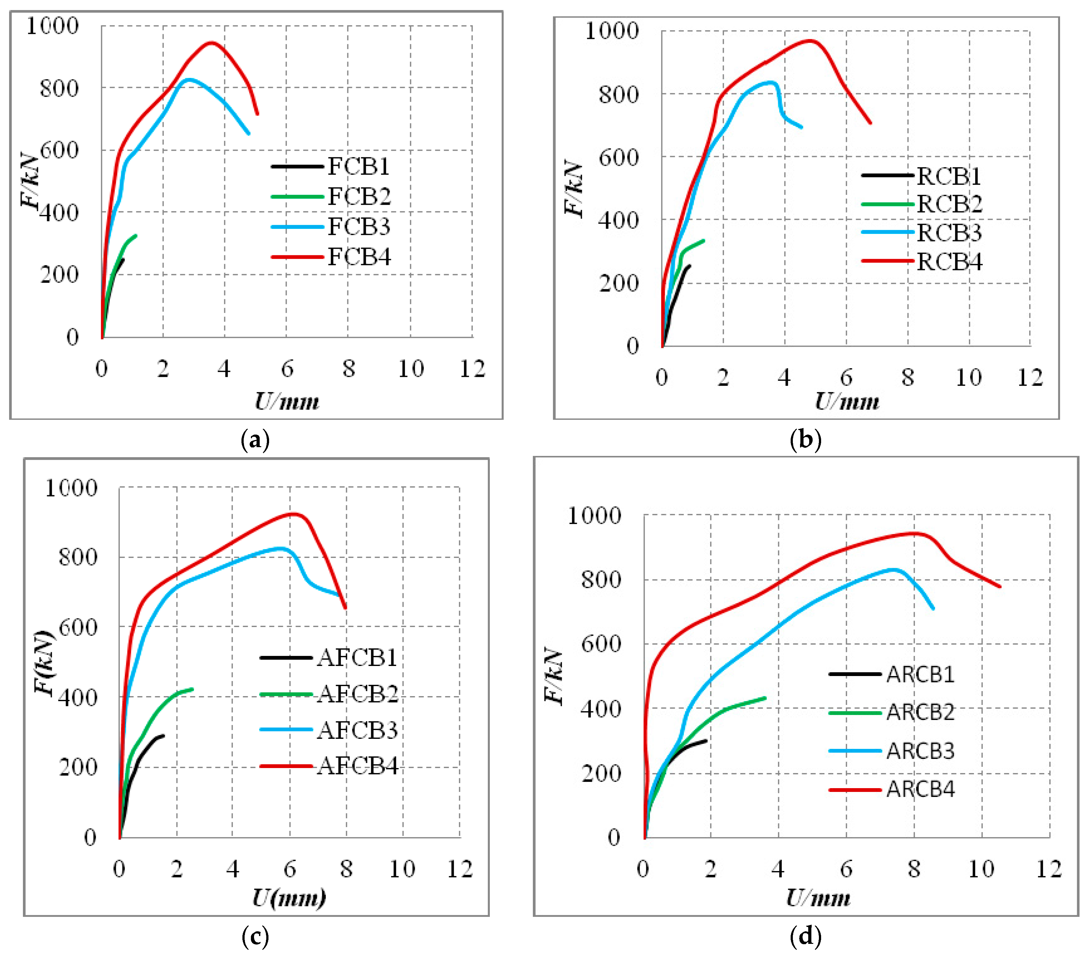
3.2.1. Loading-Displacement Curve

Please see Figure 9 for the axial loading-axial deformation curves (F-U curves), of all specimens measured on site.
From Figure 9, it can be observed that (1) the loading-displacement curve of the specimens with recycled concrete bricks bears resemblance to that with clay bricks. In contrast, the curves for specimens with no stem embedded show no sign of reduction, which indicates that the impediment is a brittle one. (2) The compressive resistance and ductility of the structure can be largely elevated via using the square-shaped wood stem, square-shaped concrete-filled steel pipe, and circular concrete-filled steel pipe, the last one among which stands as the most preferable choice. (3) With the support of fly ash blocks, the integrated structure grows in compressive strength, yield limit and ductility.

3.2.2. Force-Bearing Performance

Please see Table 3 for the split limit, loading limit and converted compressive strength. fc refers to the split limit of loading, where the first value observed applies. fu represents the loading limit, the maximum value of which applies; fm stands for the converted compressive strength, where the loading limit to cross section area ratio is used.
From Table 3, the following can be concluded: (1) Compared with the specimens of clay bricks, the masonry walls of recycled concrete bricks deliver equally matched compressive strength. (2) The application of square-shaped wood, square-shaped steel pipe and circular steel pipe helps largely to elevate the compressive strength of a structure, with the most preferable choice being the circular steel pipe. Take the last groups of specimens, or the integrated wall structure of recycled bricks, stems and fly ash masonry blocks, as an example; the application of square-shaped wood stem, square-shaped steel pipe and circular steel pipe increases the compressive strength by 41%, 174% and 208%, respectively.

3.3. Overall Compressive Performance

The compressive performance of the specimen refers to the compressive stiffness, force-bearing performance and ductility (deformative resistance). As specimens deliver identical stiffness and bearing performance, better ductility promises better overall performance. Likewise, when stiffness and ductility stand on par, or when bearing performance and ductility are identical, force bearing performance and stiffness become the decisive factors. The axial loading (F)-axial deformation (U) curve (see Figure 9) depicts the stiffness, force-bearing performance and ductility measured. Considering that the specimens vary with respect to all three parameters, the paper quantifies the process by using the product(s) of axial loading F and the corresponding axial deformation U to carry out integrated comparison of the compressive performance. Here, the product (E) reflects the work of force (F) amid the specimen’s deformation. E equals the area between the F-U curve and horizontal coordinate measured. Please see Table 4 for the measured values of E for all specimens.
The following can be concluded from Table 4: Compared with a 240 mm ×240 mm clay-brick wall, a recycled-brick wall of the same dimensions promises a 15% increase in overall compressive performance, while a 240 mm × 370 mm integrated wall of clay bricks and fly ash masonry blocks, 171%. A 240 mm × 370 mm integrated wall of recycled bricks and fly ash blocks delivers 213% more in terms of overall compressive performance compared with the 240 mm × 240 mm recycled-brick wall. That being said, the integrated wall structure of brick-stem-fly ash blocks delivers much better performance in this category. Note that with respect to the stem’s contribution to compressive strength, circular steel pipe is highest, followed by square-shaped steel pipe and then square-shaped wood. Calculation shows a 16.53-fold difference in overall compressive performance between the integrated wall of clay bricks and fly ash blocks with stem support (square-shaped steel pipe) and that without, while the figure is 11.57-fold between the integrated wall of recycled bricks and fly ash blocks with square-shaped steel pipe embedded and that without.

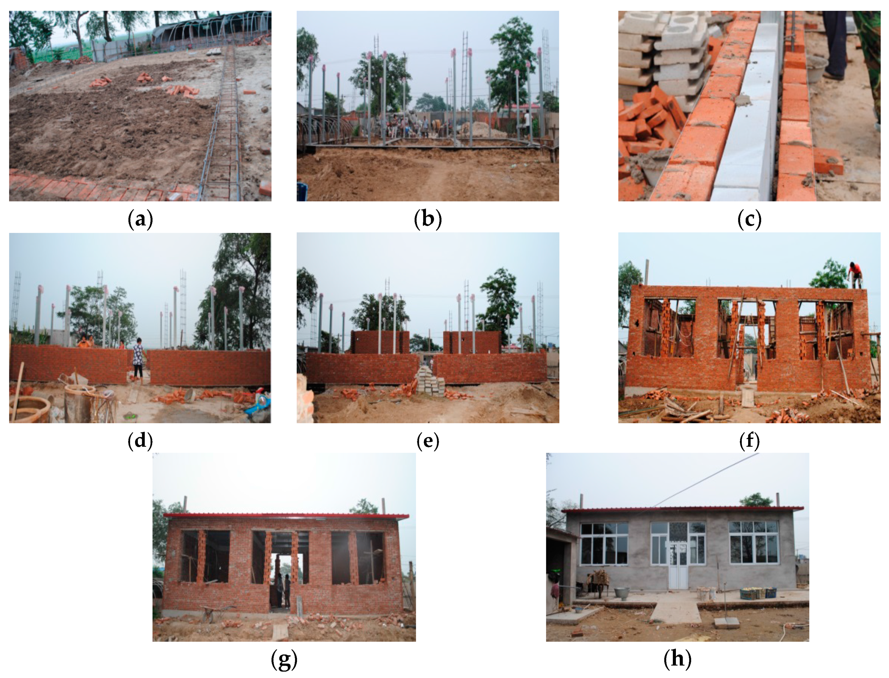
4. Engineering Practice

This paper carries out a test run of the structure in the pilot rebuilding project of a dilapidated area—where a single-story building with a floorage of 96 m2 and a story height of 3.4 m is designed to withstand earthquakes at an intensity level of seven—of Xihai village of Laoting county, Hebei province. The paper proposes the integrated fly-ash masonry structure with an insulated layer and lightweight steel stem embedded.
The requirement for engineering application states that: (1) The recycled-concrete brick masonry structure with lightweight steel stems embedded and an insulating layer sandwiched shall comply with the design and seismic requirement stipulated in the references [18] and [19]. (2) The design of ring beams and structural columns conforms to the relevant requirement listed in the reference [19]. (3) Lintels are arranged at structural portals—be it window or door—to avoid the occurrence of being out of plane. The cross section of such lintel attains a height of 100 mm, while the width remains consistent with that of the wall piece. Note that for single-floor houses, enclosed ring beams—with a height and width of 180 mm and 240 mm, respectively—are arranged right beneath the roof board. Four longitudinal Q234 re-bars with a diameter of 12 mm are embedded within the ring beams, while the stirrups applied are Q235 re-bars—6 mm in diameter—arranged with a 200-mm interval in between. (4) In terms of the wall pieces, tie bars with a diameter of 6 mm or more are installed longitudinally, with a 500-mm interval between every piece. The arrangement is made on the premise that a 600-mm-long tie bar is embedded in every piece of the inner and outer wythes. (5) Tie bars are arranged in the building of the wythes, made of standard-sized bricks-and the fly-ash blocks; therefore, the bars can be vertically embedded and properly sandwiched in between the mortar. The vertical and horizontal intervals of such bars shall not exceed 400 and 800 mm, respectively.
In terms of the choice of material, the recycled-concrete bricks-consistent with clay bricks in size-shall display a strength of MU10 or more. The dimensions of the fly-ash masonry blocks are jointly decided by wall thickness and the insulating performance required. The structural columns shall enjoy a no less than C20 concrete strength. With mortar poured in as an adhesive agent, the wythe pieces and the masonry blocks are bound by z-shaped reinforced steel with a diameter of 4 mm.
Please see Figure 10a,b for the arrangement plan of the main structure and Figure 11a–h for the illustration of the construction site.
The following can be concluded from the household inquiry: (1) The application of the integrated masonry structure with stem and insulating layers promises a streamlined construction procedure, easily-accessible raw materials and affordable cost of constriction. (2) In the summertime, the room temperature of the cottage—with no air conditioner or fan—is 3–5 °C lower than that of other houses in the village, meaning that the structure helps reduce electricity costs. In the wintertime, the structure increases the room temperature (with only cooking heat indoors) by 5–8 °C. The extraordinary thermal insulation performance decreases the heating cost for the household. Overall, the feedback from the household considered and the citizens of this village is fairly good.

5. Conclusions

(1) The clay-brick structure (with no stem), the recycled-concrete-brick structure, the integrated masonry structure of recycled concrete bricks and fly ash blocks, and the integrated structure of recycled concrete bricks and fly ash masonry blocks deliver similar failure processes, showing classic signs of brittle fractures. The square-shaped wood, square-shaped concrete-filled steel pipe and circular concrete-filled steel pipe largely elevate the compressive resistance, working and deformative performances of the integrated structure.
(2) The integrated structure of clay bricks and fly ash blocks and the structure of recycled-concrete bricks and fly-ash blocks promise productive cooperation between the masonry blocks and bricks, showing no visible sign of detachment.
(3) In comparison with a brick wall with an insulating layer sandwiched in between, the integrated wall structure of bricks and fly ash blocks is a more preferable choice in terms of compressive performance and ductility. That being said, the integrated wall structure of brick-stem-fly ash blocks delivers much better compressive performance and ductility. Note that in regard to the stem’s contribution to compressive strength, circular steel pipe is highest, followed by square-shaped steel pipe and then square-shaped wood.

Acknowledgments

This research was conducted with the financial support of the National Natural Science Foundation of China (NO. 51508009) and the Project was supported by the Beijing Postdoctoral Research Foundation (2015ZZ-29), National Science and technology support program of China (NO. 2015BAL03B01).

Author Contributions

Suizi Jia wrote the manuscript; Suizi Jia, Yan Liu, Wanlin Cao, Zhongyi Zhou designed the experiments. Suizi Jia, Wanlin Cao and Yuchen Zhang modified the final paper.

Conflicts of Interest

The authors declare no conflict of interest.

Abbreviations

The following abbreviations are used in this manuscript:
MDPIMultidisciplinary Digital Publishing Institute
DOAJDirectory of open access journals
TLAThree letter acronym
LDlinear dichroism

References

  1. GSA2003. Progressive collapse analysis and design guidelines for New Federal Office Buildings and Major Modernization Project. Available online: http://bbs.co188.com/thread-9221826-1-1.html (accessed on 10 May 2016).
  2. Niroumand, H.; Kassim, K.A. Comparison of compressive strength in mud bricks with shred tires and concrete particles as sustainable materials. Electron. J. Geotech. Eng. 2010, 15, 1151–1158. [Google Scholar]
  3. Valdés, G.A.; Rapimán, J.G. Physical and mechanical properties of concrete bricks produced with recycled aggregates. Inf. Technol. 2007, 18, 81–88. [Google Scholar]
  4. Corinaldesi, V.; Monosi, S.; Moriconi, G. Effect of different recycled aggregates on mortar performance. In Proceedings of the Sustainable Construction Materials and Technologies International Conference on Sustainable Construction Materials and Technologies, Coventry, United Kingdom, 11–13 June 2007; pp. 59–62.
  5. Corinaldesi, V.; Moriconi, G. Concrete and mortar performance by using recycled aggregates. In Proceedings of the International Conference on Sustainable Waste Management and Recycling: Construction Demolition Waste, Wuhan, China, 18–22 October 2004; pp. 157–164.
  6. Yoshimura, K.; Kikuchi, K. Experimental study on seismic behavior of masonry walls confined by R/C frames. Appl. Mech. Mater. 1995, 15, 41–48. [Google Scholar]
  7. Tomazevic, M.; Lutman, M.; Petkovic, L. Seismic behavior of masonry walls: Experimental simulation. J. Struct. Eng. 1996, 122, 1040–1047. [Google Scholar] [CrossRef]
  8. Riddington, J.R.; Ghazali, M.Z. Hypothesis for shear failure in masonry joints. Proc.-Inst. Civ. Eng. 1990, 89, 89–102. [Google Scholar] [CrossRef]
  9. Lotfi, H.R.; Shing, P.B. Interface model applied to fracture masonry structures. J. Struct. Eng. 1994, 120, 63–80. [Google Scholar] [CrossRef]
  10. Banting, B.; El-Dakhakhni, W. Force-and displacement-based seismic performance parameters for reinforced masonry structural walls with boundary elements. J. Struct. Eng. 2012, 2, 71–82. [Google Scholar] [CrossRef]
  11. Shedid, M.T.; Hamid, A.A.; Drysdale, R.G. Ductility of reinforced masonry shear walls and impact of incomplete grouting. In Proceedings of the 10th Canadian Masonry Symposium, Banff, Alberta, 8–12 June 2005.
  12. Oak Ridge National Laboratory. New building insulation to combat wet, warm, wall worries. Eng. Syst. 2007, 24, 84–85. [Google Scholar]
  13. Yang, D.J.; Zhang, Z.W. Analysis on earthquake resistance and affective factors of concrete hollow block composite wall structures. New Build. Mater. 2010, 3, 42–44. [Google Scholar]
  14. Liu, C. Shaking table model design for brick masonry structures strengthened with an externally steel reinforced mesh mortar layer. Struct. Eng. 2012, 6, 72–78. [Google Scholar]
  15. Zheng, N.N.; Li, Y.M.; Pan, Y. Seismic behavior of low masonry structure with core-tie-column. J. Southwest Jiaotong Univ. 2011, 46, 24–29. [Google Scholar]
  16. Lidija, K.; Ljubomir, T.; Vladimir, G.; Mihail, G. Experimental and analytical investigation of seismic stability of masonry walls at beauharnois powerhouse. Bull. Earthq. Eng. 2010, 8, 421–450. [Google Scholar]
  17. Li, J.; Cao, W. The Heat Transfer Coefficient of Recycled Concrete Bricks Combination with EPS Insulation Board Wall. Math. Probl. Eng. 2015, 2015. [Google Scholar] [CrossRef]
  18. Ministry of Housing and Urban-Rural Development of the People's Republic of China. GB50011-2010; Code for Seismic Design of Buildings; China Architecture Building Press: Beijing, China, 2010; Available online: http://bbs.co188.com/thread-4941150-1-1.html (accessed on 10 May 2016).
  19. Ministry of Housing and Urban-Rural Development of the People's Republic of China. GB 50003-2011; Code for Design of Masonry Structures; China Architecture Building Press: Beijing, China, 2011; Available online: http://bbs.co188.com/thread-5107290-1-1.html (accessed on 10 May 2016).
Figure 1. Dimensions and structural details for specimens with 240 mm × 240 mm cross section: (a) standard specimen; (b) square-shaped wood embedded; (c) square-shaped steel pipe embedded; and (d) circular steel pipe embedded.
Applsci 06 00146 g001
Figure 2. Dimensions and structural details for specimens with 240 mm × 370 mm cross section: (a) standard specimen; (b) square-shaped wood embedded; (c) square-shaped steel pipe embedded; and (d) circular steel pipe embedded.
Applsci 06 00146 g002
Figure 3. Preparation of materials and specimens: (a) recycled concrete bricks and clay bricks; (b) fly ash blocks; (c) square-shaped wood embedded; (d) lightweight concrete-filled steel stem; and (e) making of the specimens.
Applsci 06 00146 g003
Figure 4. Loading imposed: (a) loading device; and (b) test scene.
Applsci 06 00146 g004
Figure 5. Failure states of FCB1-FCB4: (a) FCB1; (b) FCB2; (c) square-shaped wood; (d) FCB3; (e) square-shaped steel pine; (f) FCB4; and (g) circular steel pine.
Applsci 06 00146 g005
Figure 6. Failure states of RCB1–RCB4: (a) RCB1; (b) RCB2; (c) square-shaped wood; (d) RCB3; (e) square-shaped steel pine; (f) RCB4; and (g) circular steel pine.
Applsci 06 00146 g006
Figure 7. Failure states of AFCB1–AFCB4: (a) AFCB1; (b) AFCB2; (c) AFCB3; and (d) AFCB4.
Applsci 06 00146 g007
Figure 8. Failure states of ARCB1–ARCB4: (a) ARCB1; (b) ARCB2; (c) ARCB3; and (d) ARCB4.
Applsci 06 00146 g008
Figure 9. Axial loading-axial displacement curve: (a) Group One; (b) Group Two; (c) Group three; and (d) Group four.
Applsci 06 00146 g009
Figure 10. Arrangement plan of structure: (a) floor plan of structure; and (b) elevation drawing of structure.
Applsci 06 00146 g010
Figure 11. The construction site of the integrated fly-ash masonry structure with an insulated layer and lightweight steel stem embedded: (a) groundsill construction; (b) construction of lightweight concrete-filled steel stem; (c) construction of insulating layer for fly-ash masonry blocks; (d) wall construction on the north side; (e) wall construction on the south side; (f) ring beam construction; (g) roofing construction; and (h) completion of major structure of rural housing.
Applsci 06 00146 g011
Table 1. Specifications.
Group No.Specimen No.ConfigurationDimensions
Group One Clay BricksFCB1No support embedded240 mm × 240 mm × 720 mm
FCB2Square-shaped wood embedded
FCB3Square-shaped steel pipe embedded
FCB4Circular steel pipe embedded
Group Two Recycled Concrete BricksRCB1No support embedded240 mm × 240 mm × 720 mm
RCB2Square-shaped wood embedded
RCB3Square-shaped steel pipe embedded
RCB4Circular steel pipe embedded
Group Three Clay Bricks + Fly Ash BlocksAFCB1No support embedded240 mm × 370 mm × 720 mm
AFCB2Square-shaped wood embedded
AFCB3Square-shaped steel pipe embedded
AFCB4Circular steel pipe embedded
Group Four Recycled Concrete Bricks + Fly Ash BlocksARCB1No support embedded240 mm × 370 mm × 720 mm
ARCB2Square-shaped wood embedded
ARCB3Square-shaped steel pipe embedded
ARCB4Circular steel pipe embedded
Table 2. Material performance.
Materialfc N/mm2fy N/mm2fu N/mm2
Clay Bricks10.39--
Recycled Bricks10.95--
Fly-ash Masonry Blocks2.58--
Mortar10.03--
Recycled Concrete36.5--
Square-shaped Wood--16.6
Square-shaped Steel Pipe-308.33393.67
Circular Steel Pipe-341.67455.24
fc represents the compressive strength of clay bricks, recycled bricks, recycled concrete and mortar; fy stands for the yield strength of the steel; and fu is steel’s limit with respect to tensile strength.
Table 3. Split limit, loading limit and converted compressive strength measured for four groups of specimens.
Group No.Specimen No.fc/(N/mm2)fu(N/mm2)fc/fufm/MPafm (Relative Values)
Group OneFCB11502510.604.361.00
FCB21803300.555.731.31
FCB34308300.5214.413.31
FCB45309450.5616.413.76
Group TwoRCB11752560.684.441.00
RCB22103460.616.011.35
RCB35008600.5814.933.36
RCB47009680.7216.813.79
Group ThreeAFCB11752980.593.361.00
AFCB22504250.594.791.43
AFCB34008150.499.182.73
AFCB44609250.5010.423.10
Group FourARCB11653080.543.471.00
ARCB22504350.574.901.41
ARCB34258450.509.522.74
ARCB44759500.5010.703.08
Table 4. Relative energy consumption measured.
Group No.Specimen No.Energy Consumption E/kN·mmΔe
Group OneFCB11151.00
FCB22532.19
FCB3315427.31
FCB4385833.42
Group TwoRCB11331.00
RCB23372.53
RCB3280321.03
RCB4515738.70
Group ThreeAFCB13121.00
AFCB28182.62
AFCB3547417.53
AFCB4618919.82
Group FourARCB14171.00
ARCB211412.73
ARCB3524112.57
ARCB4835120.02

