Article

A Micro-Coordinate Measurement Machine (CMM) for Large-Scale Dimensional Measurement of Micro-Slits

1
Department of Finemechanics, Tohoku University, Sendai 980-8579, Japan
2
Engineering Department, MMC RYOTEC Corporation, Gifu 503-2301, Japan
*
Author to whom correspondence should be addressed.
These authors contributed equally to this work.
Submission received: 17 March 2016 / Revised: 7 May 2016 / Accepted: 10 May 2016 / Published: 18 May 2016
(This article belongs to the Special Issue Design and Applications of Coordinate Measuring Machines)

Abstract

:
This paper presents a micro-coordinate measuring machine (micro-CMM) for large-scale dimensional measurement of a micro-slit on a precision die coater by using a shear-mode micro-probe. A glass micro sphere with a nominal diameter of 52.3 μm was attached on one end of a tapered glass capillary tube as a probe tip ball. The micro-slit width of a slot die coater with a nominal slit width of 85 μm was measured by the micro-CMM. The probe tip was placed in the slit for the measurement. The effective working length of the probe was confirmed experimentally to be at least 1 mm. In order to measure the gap width uniformity over the entire slot die length of 200 mm, an air-bearing linear slide with a travelling stroke of 300 mm was employed in the micro-CMM to position the probe along the length direction of the slot die. The angular alignment error and the motion error of the air-bearing linear slide as well as those of the stages for positioning the probe along the direction perpendicular to the length direction of the slot die were investigated for evaluation of the expanded uncertainty of gap width measurement.

1. Introduction

Precisely machined micro-features have been utilized widely with the development of micro-fabrication technologies such as micro-cutting [1,2], micro- electrical discharge machining (EDM) [3,4], micro- and nano-lithography [5,6], nanoimprint [7] and micro-molding [8]. In particular, more precision micro-features with high aspect ratios represented by deep micro-holes and micro-slits are utilized for precision tools and measuring instruments that require sub-micrometric or nanometric dimensional accuracies. The requirements for dimensional measurements of precision micro-features with high aspect ratios are thus increasing. The micro-slit of a slot die coater is a good example of such precision micro-features. The slot die is a precision tool for coating of functional liquid materials on the surface of a substrate such as a glass plate or a film. On the top of the slot die coater is a micro-slit from which the liquid material is extruded. The micro-slit has a high aspect ratio with a gap width in the order of 100 μm and a depth of more than 10 mm. Since the gap width of the micro-slit as well as its uniformity along the length direction of the slot die coater is a key parameter for determining the coating quality, it is necessary to measure the micro-slit gap width and its uniformity accurately.
For dimensional measurement of micro-features with high-aspect ratios, the micro-coordinate measurement machine (micro-CMM) with a micro-probing system is one of the prospective measuring instruments because the inside of a micrometric feature such as a micro-hole or a micro-slit can be detected by the micro-probe with a micro-tip ball. On the other hand, the accuracy and reliability of the micro-probing system are determined by the positioning accuracy of the probe qualification of the probe tip, measurement strategies, and so on. The plastic deformation caused by the contact force between the probe and the measured surface is also a main error source, which requires the probing system to have a high sensitivity for detecting the probe–surface contact so that a small contact force can be achieved for reduction of the plastic deformation [9].
The contact detection is typically carried out by detecting the elastic deformation of the springs for supporting the stylus of a micro-probe. Different kinds of sensors have been integrated into the micro-probe for this purpose. For example, three integrated strain gauges have been employed to detect the probe–surface contact [10]. Optical systems have also been integrated into the micro-probes for contact detection. Cui et al. have proposed a three-dimensional fiber probe for the measurement of micro parts. [11]. Muralikrishnan et al. have proposed a fiber probe with an ellipsoidal tip for three-dimensional measurement on micro-features [12]. Fan et al. have developed low-cost and high precision micro-CMM by utilizing the focusing probe [13]. Schwenke et al. have developed an opto-tactile sensor for the contact detection of a micro-probe in two and three directions at Physikalisch-Technische Bundesanstalt (PTB) in Germany [14], where the micro-probe has a tip ball of 60 μm in diameter. The probe displacement can be detected by using an optical beam focused on the probe tip ball. Takaya et al. have proposed a nano-probe system based on the laser-trapping technique [15,16]. A micro-sphere with a diameter of 8 μm, which is held by the focused laser beam, is used as the probe tip ball with a piconewton measuring force. Such optical-based detection methods are more sensitive than the traditional strain gauges. However, the effective working distance of the probe is confined by the numerical aperture of the focusing lens and it is difficult to measure the inside of a high-aspect ratio micro-feature.
Detection of electric contact has been applied for micro-probing systems for highly sensitive probe-surface contact detection. Masuzawa et al. have introduced a micro-probe, in which the probe-surface contact is detected based on the electrical contact. Since the a micro-probe tip is attached on the end of a long and sharp stylus shaft, the probe can be used to measure the inside of micro-holes [17,18]. The micro-probe tip has a pyramidal edge and it can detect the contact in one direction. As for the multi-axis detection of contact, Weckenmann et al. have developed a probing technique based on the method of scanning tunneling microscopy (STM) [19], in which a spherical probe tip is employed. However, the applications of such methods are only effective for measurement of conductive materials.
Improvement of sensitivity for contact detection can also be achieved by applying mechanical vibrations to the micro-probe. Bauza et al. have proposed a vibrating shank for measurement of the inside of a micro-hole [20,21]. A fiber with a diameter of 7 μm is vibrated in one direction by a crystal resonator, which is used as a virtual micro-probe for contact detection in one axis. The effective diameter of the vibrating fiber probe is approximately 30 μm. With respect to a probe with multi-axis detection, Claverley et al. have developed a three-dimensional vibrating probe composed of PZT sensors and actuators [22,23]. The probe tip of the three-dimensional vibrating probe has a spherical tungsten tip with a diameter of approximately 70 μm. Murakami et al. have presented an optical fiber probe which has a glass tip ball with a diameter of 5–50 μm [24,25]. Since the vibrating probe allows the use of a probe stylus with a lower stiffness, it results in a lower probe–surface contact force. In addition, it is an effective means for the vibrating probe tip to reduce the influence of adhesion force of the measured surface against the probe. However, the measurement is influenced by the water layers on both the measured surface and the probe surface [9,22,25]. In responding to this problem, the authors have developed a shear-mode micro-probe, which can reduce the influence of the water layers through detecting the interaction force between the probe and the measured surface over the water layers [26]. It has been demonstrated that the shear-mode detection probe can achieve nanometric resolution and probing repeatability.
The motivation of this research is to apply the shear-mode micro-probe for measurement of the gap width of the micro-slit on a precision slot die coater. The precision slot die is composed of two precision flat plates [27] made of stainless steel with a length of 200 mm. The two precision flat plates are separated with a gap with a nominal gap width of 85 μm to form the micro-slit on the coater edge. It is required to make gap width measurement of the micro-slit with the expanded uncertainty of less than 100 nm [28]. Traditionally, mechanical feeler gauges have been used for the measurement of micro-slit gap width. However, the mechanical feeler gauge often induces damages on the edge areas of the micro-slit due to the large contact force. Although a CCD camera based optical system [28] has been proposed for non-contact measurement of the micro-slit gap width, it is difficult for the optical system to achieve sub-micrometer resolutions because of the diffraction limit of the optical system. As for the detection of single edge position, it can be achieved by using the optical system. However, with regard to the precision measurement of the slit gap width, it is necessary to detect the positions of two edges quantitatively. Therefore, the resolution in lateral direction is one of the important requirement for the gap width measurement. In addition, it cannot be used for measuring the gap width inside the micro-slit. Recently, a non-contact measurement system with a higher resolution by using a capacitive displacement sensor has been developed [27]. However, the measurable minimum gap width of the electric gap sensor is limited to 150 μm, due to the sensor thickness. Compared with the measurement techniques mentioned above, a micro-CMM is more effective for such a measurement in terms of the measurable minimum gap width and measurement resolution, as well as the flexibility and accessibility to the inside of the micro-slit.
This paper presents a micro-CMM specifically designed for the slit width measurement of the precision die coater. In addition to the newly developed shear-mode micro-probe, an air-bearing linear slide with a travelling stroke of 300 mm was employed in the micro-CMM so that there is a uniformity of the gap width over the entire length of the micro-slit of 200 mm. This is a significant difference from an existing micro-CMM that can only cover a measurement length from several millimetres to several centimetres. The calibration of the conventional micro-CMMs is carried out by using the calibration artifact with a length of 20 mm at the maximum [29]. Therefore, a longer travelling range of the probe positioning system is essential for the gap width measurement of the slot die. The effective working length of the shear-mode micro-probe is designed to be 1 mm, which is longer than that of the existing micro-probes [25,30], so that the inside of the micro-slit can be accessed by the probe tip while avoiding the influence of the chamfered edges of the precision parts forming the micro-slit. In order to shorten the measurement time, a measurement strategy of gap width measurement based on two probing points is also introduced. Next, a description of the experimental setup for the micro-CMM, experiments and uncertainty analysis of the measurement results are presented.

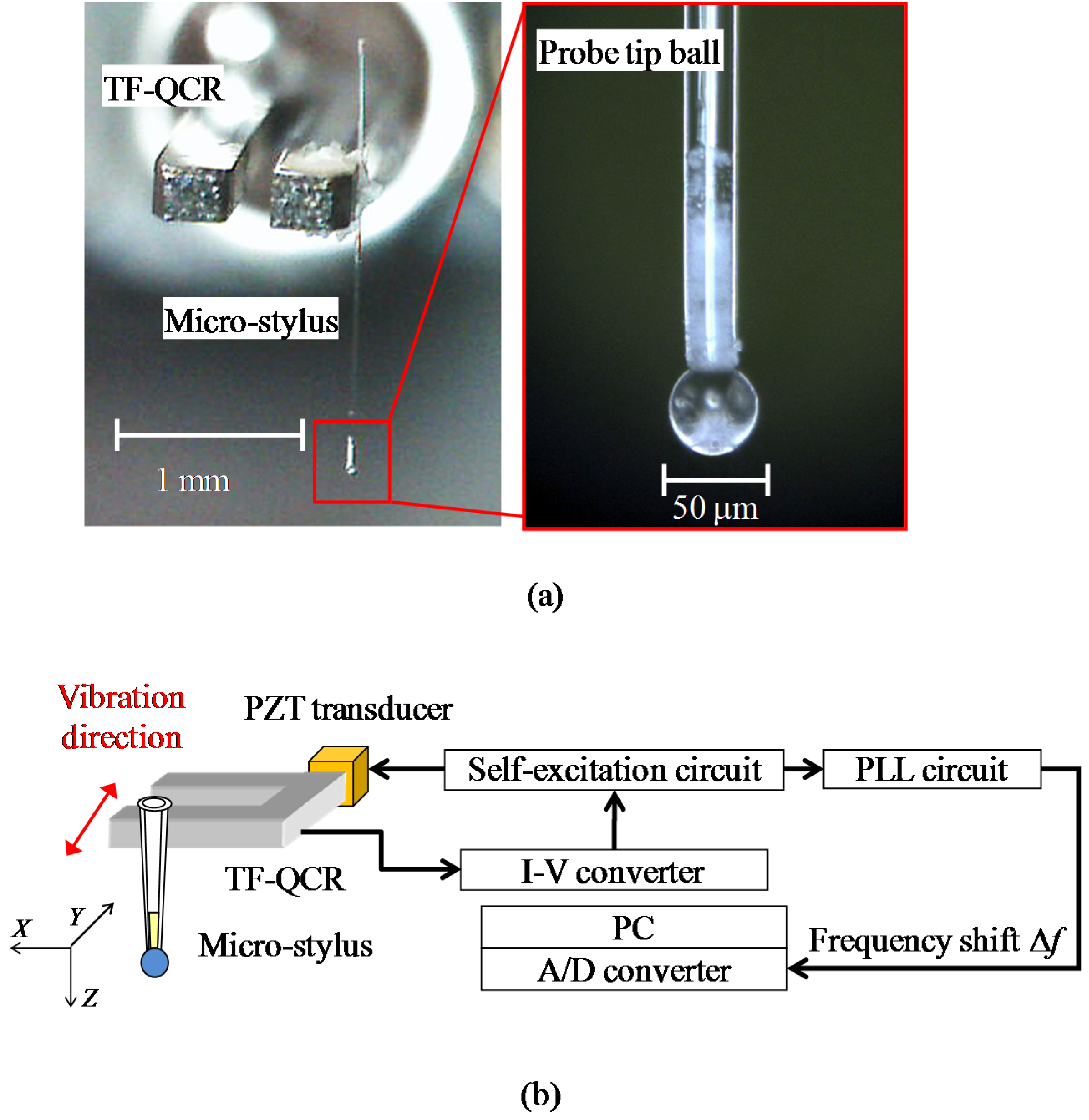
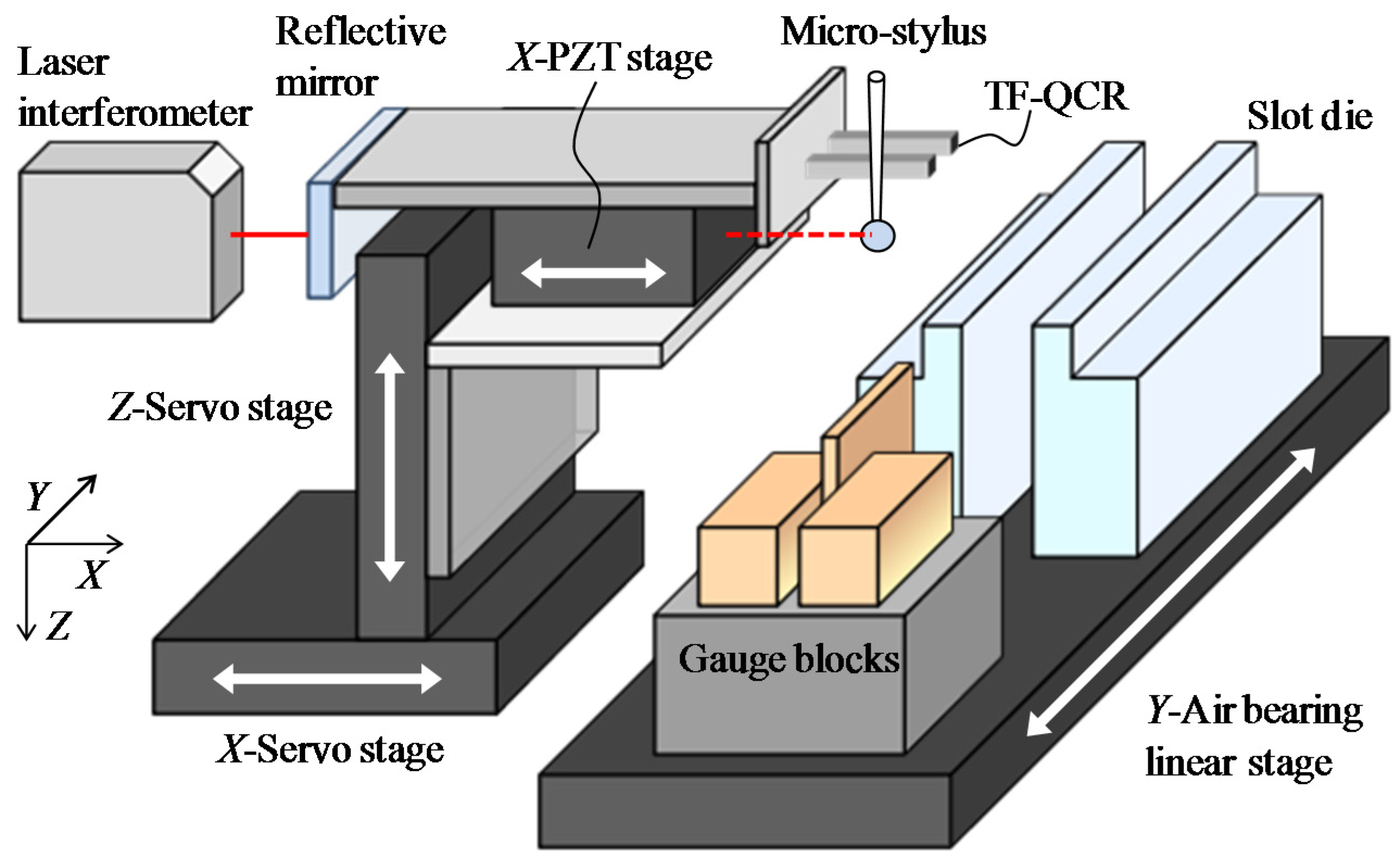
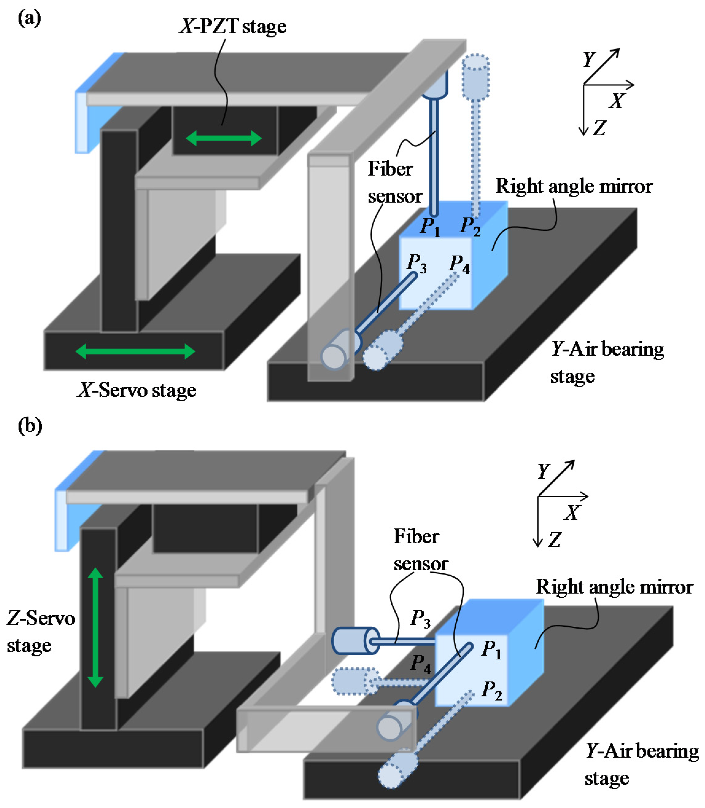
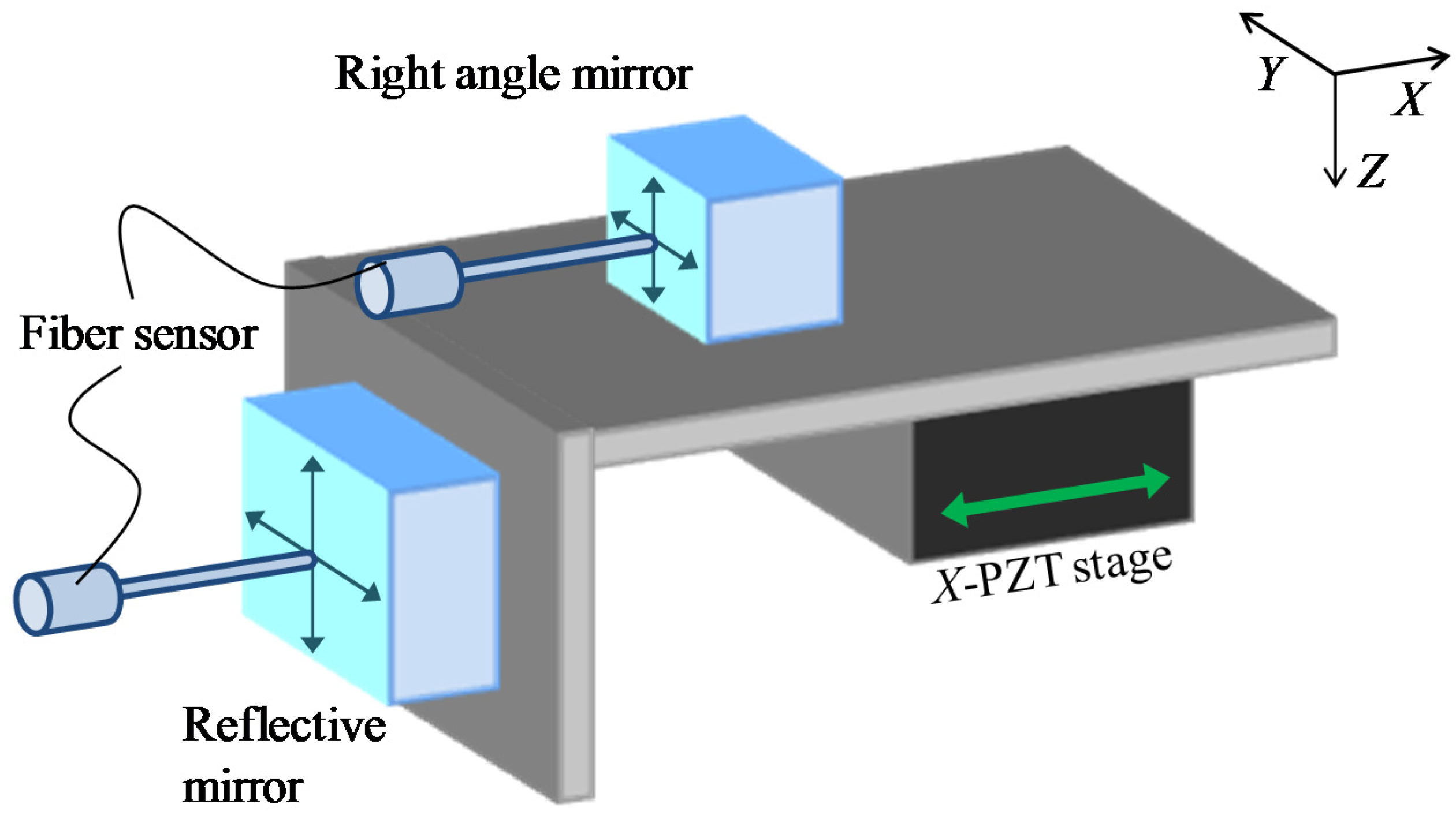
2. Experimental Setup for the Micro-CMM

Figure 1a shows the photographs of the shear-mode micro-probe. The micro-stylus is composed of a glass micro-stylus shaft and a glass micro-sphere. The stylus shaft is made of a capillary glass tube which is thermally pulled by using a commercially available glass pipette puller. A micro-glass sphere with a nominal diameter of 52.6 ± 3.2 μm (Certified size standard Cat No. 9050, Duke Scientific Corporation, California, CA, USA) [31] is attached on one end of the glass micro-stylus by thermosetting resin. The diameter of the commercially available glass micro-sphere was selected based on the nominal gap width of the precision slot die. Figure 1b shows the schematic of a shear-mode micro-probe. The micro-stylus is then attached on a tuning fork quartz crystal resonator (TF-QCR). A PZT transducer is employed to vibrate the assembly, which is composed of the TF-QCR, the micro-stylus, and the micro-sphere at the resonance frequency of the TF-QCR. The variation of the vibration frequency is detected by the TF-QCR based on the piezoelectric effect of the quartz crystal. The vibration of the TF-QCR is detected and amplified by current-to-voltage (I-V) converter. The output of the I-V converter is then utilized to keep the vibration frequency constant by using a self-excitation circuit that consists of a phase locked loop circuit (PLL). It should be noted that the actual resonance frequency of the TF-QCR used in the assembly is confirmed to be approximately 30 kHz, which is smaller than that of the single TF-QCR element of 32.768 kHz, due to the influence of the masses of the micro-stylus and the micro-sphere attached on the TF-QCR. The vibration direction is set in parallel with the measuring surface.
To determine the trigger point for the probing of the micro-probe to the measured surface, the interaction force of the water layer on the measured surface against the probe is detected through detecting the change of the probe vibration with the TC-QCR [26]. When the tip ball of the vibrating probe contacts with the water layer of the measured surface, the frequency of the probe vibration is shifted due to the adhesion force of the water layer. The output of the TF-QCR is input to a phase locked loop (PLL) circuit for detection of the amount of frequency shift. The PLL circuit output is then employed as the trigger signal for the probing of the micro-probe to the measured surface. The PLL output signal is fed into analog-to-digital (A/D) converter of a personal computer (PC). A certain frequency shift amount is set to be a threshold of the trigger signal.
Figure 2 shows a schematic diagram of the micro-CMM by using the shear-mode micro-probe. The probe is mounted on the PZT-driven linear stages (P-621.2CL and P-621.1ZCL, PI), which can be moved in the X- and Z-directions independently, for fine positioning of the probe. The stroke and resolution of the PZT stages are 100 μm and 1 nm, respectively. The positioning accuracy in the X- and Z-directions are ±2 nm and ±1 nm, respectively. Since the gap width of the slot die is calculated based on the X-directional probe displacement, a commercial laser interferometer (RLE10, RENISHAW) with a resolution of 0.39 nm is employed for the measurement of the X-directional probe displacement. A plane mirror is mounted on the opposite side of the probe on the X-direction PZT stage as a moving mirror for the laser interferometer. In order to reduce the influence of the Abbe error, the optical axis of the laser interferometer is aligned with the center of the probe tip. The PZT stages are mounted on the DC servo motor driven positioning stages (M-111.1DG, PI) for coarse positioning of the probe in the X- and Z-directions. The stroke and resolution of the servo motor coarse stages are 25 mm and 6.9 nm, respectively. The positioning accuracy resolution of the servo motor stages are 0.1 μm. For positioning the probe in the Y-direction, an air bearing linear slide (TAAT30SL-19+C, NTN) with a travel stroke of 300 mm is employed. The resolution and positioning accuracy of the Y-directional linear slide are 20 nm and ±0.1 μm, respectively. The precision slot die with a length of 200 mm is placed on the moving table of the Y-directional linear slide for measurement.
When a typical CMM is employed for measuring the gap distance between two parallel surfaces, at least three points on one surface are probed first to define the surface. A point on the other surface is then probed for obtaining the coordinates of the point. The gap distance between the two surfaces can thus be accurately obtained from the coordinates of the point on the second surface with respect to the defined first surface even if the normal of the surfaces are not parallel/vertical to the coordinate axes of the CMM. However, it is necessary to conduct the probing at least three points on the first surface, which is a time-consuming process. In order to shorten the measurement time, the gap width of the precision slot die is measured in the micro-CMM, as shown in Figure 3, by probing only one point on each of the surfaces forming the micro-slit under the condition that the axes of the X-directional positioning stages are carefully aligned to be parallel to the normal of the slit surfaces and perpendicular to the Y-axis of the linear slide.
Consequently, the gap width of the slot die ws can be calculated by the following equation.
w s = L 34 + D e + 2 s t s
where L34 is the distance between the trigger positions P3 and P4 along the X-direction. De is the effective diameter of the probe tip ball. sts is the thickness of the water layer on the slot die at the trigger point. The effective diameter De is influenced by the water layer on the measured surface, the stiffness of the stylus shaft, and so on. The probing can be carried out by the shear-mode micro-probe through detection of the interaction between the water layer on the measured surface and that on the surface of the probe tip ball. Similar to the authors’ previous research [32], on-line qualification of the effective diameter De is carried out soon before the gap width measurement to reduce the combined standard uncertainty caused by the variations in the water layer thickness of the water layer, which is dependent on measurement conditions such as temperature, humidity, and surface materials. Firstly, the effective diameter of the probe tip is estimated by using a calibrated artifact. A grade K gauge block (Mitsutoyo) with a thickness of 100 μm and a tolerance of ±10 nm is used as the calibrated artifact. The tolerance of the gauge block was determined based on the calibration certification. Both the slot die and the gauge block are made of stainless steel. The effective diameter De can be estimated by:
D e = L 12 w b 2 s t b
where wb is the thickness of the calibrated artifact, L12 is the distance between the trigger points P1 and P2 along the X-direction, and stb is the thickness of the water layer on the calibrated artifact.
The stroke of the PZT stage used in the micro-CMM is 100 μm. It is not enough to move the probe across the calibrated artifact for probing the two sides of the artifact. The X-servo motor stage is therefore used to move the probe to the opposite side of the artifact for the probing at P2 after the probing at P1. In order to prevent the motion error induced by the Z-servo motor stage, it is desired to move the probe in the X-direction without lifting the probe up in the Z-direction. For this purpose, the artifact is moved by the Y-slide table in the negative Y-direction until the moving path of the probe along the X-direction is not blocked by the artifact. After the probe is moved across the artifact by the X-servo motor stage, the artifact is moved back to its original position by the Y-slide table in the positive Y-direction. Finally, the probing at P2 is carried out by using the X-directional PZT stage. As a result, Equation (1) can be rewritten as follows.
w s = L 34 + D e + 2 s t s = L 34 + L 12 w b 2 ( s t b s t s )
Since stb is almost the same as sts, the influence of the water layer thickness can be cancelled. Figure 4 shows the vibration frequency shifts when probing the slot die and the gauge block, respectively. The vertical axis in Figure 4 indicates the frequency shift ∆f and the horizontal axis indicates the probe displacement in the X-direction. When the frequency shift is extended to the trigger threshold, the probe position in the X-direction is measured by the laser interferometer to determine the trigger point of the probing. The probe tip is then retracted back from the measured surface immediately. As shown in Figure 4, if the frequency shift ∆f of 0.1 Hz is set to be the trigger threshold for the probing, the difference of the probe displacements for the two results in Figure 4 is less than 2 nm. Consequently, the gap width of the slot die can be measured accurately by the on-line qualification of the effective diameter of the tip ball.
After the on-line qualification procedure, the probe tip is positioned inside of the micro-slit of the slot die for the gap width measurement based on Equation (1). The gap width uniformity can also be obtained by measuring the gap widths at different Y-directional positions through moving the slot die with the Y-directional linear slide.

3. Experimental Result and Discussion

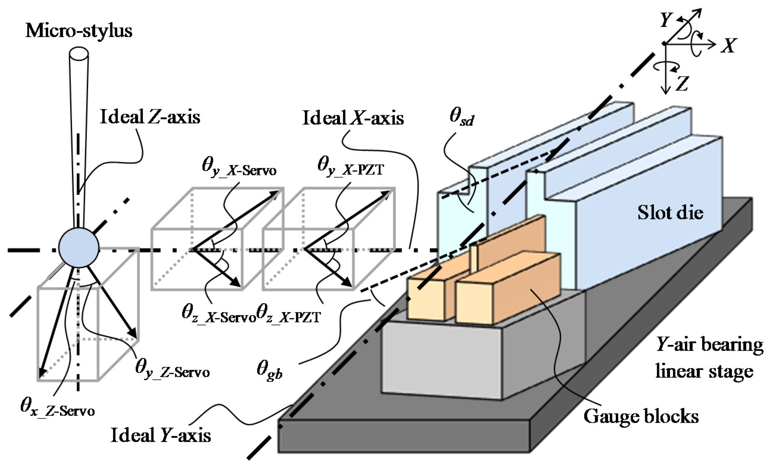
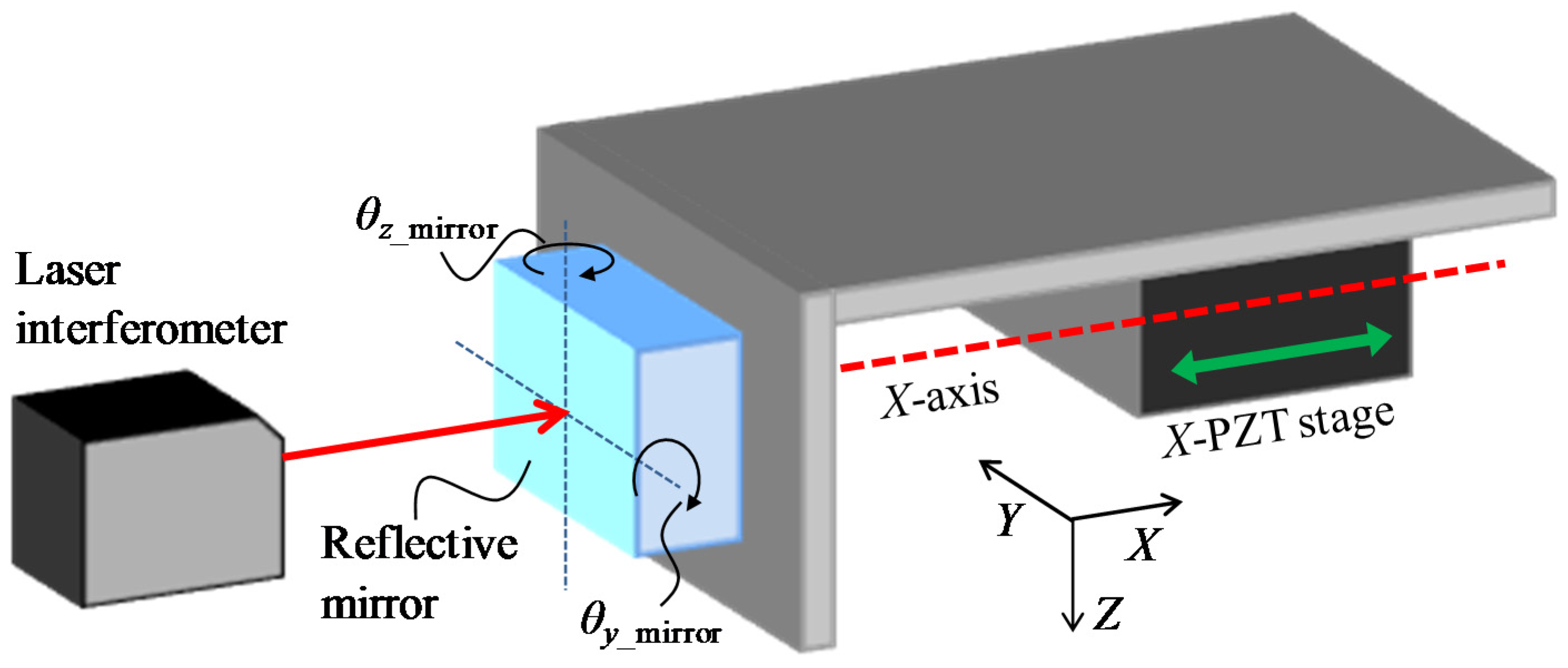
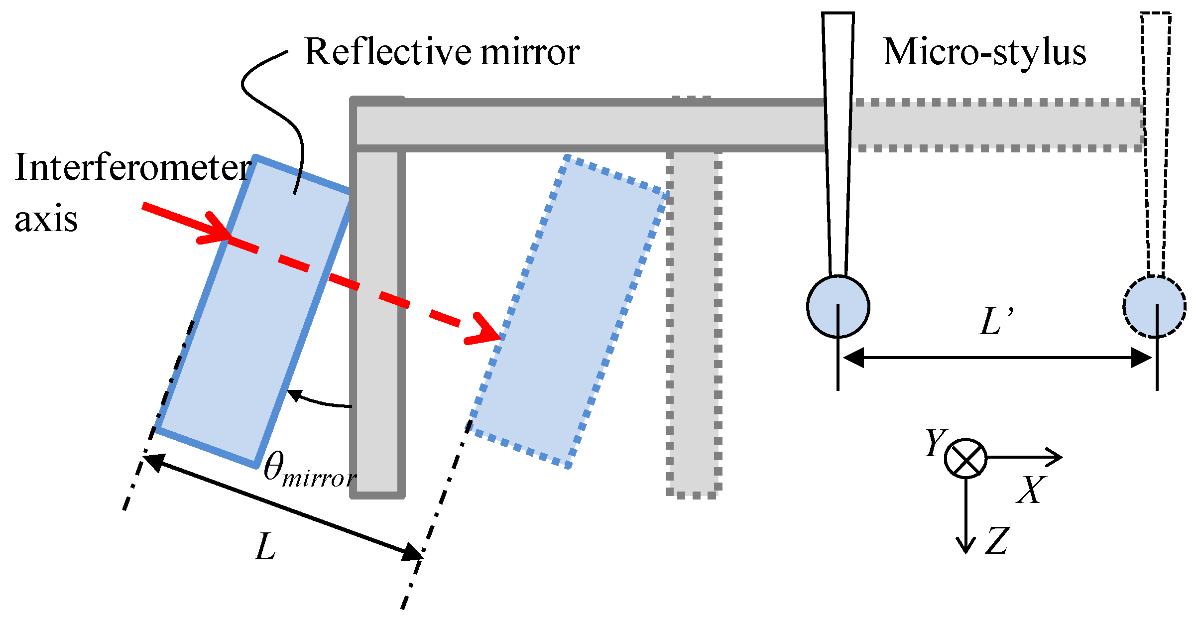
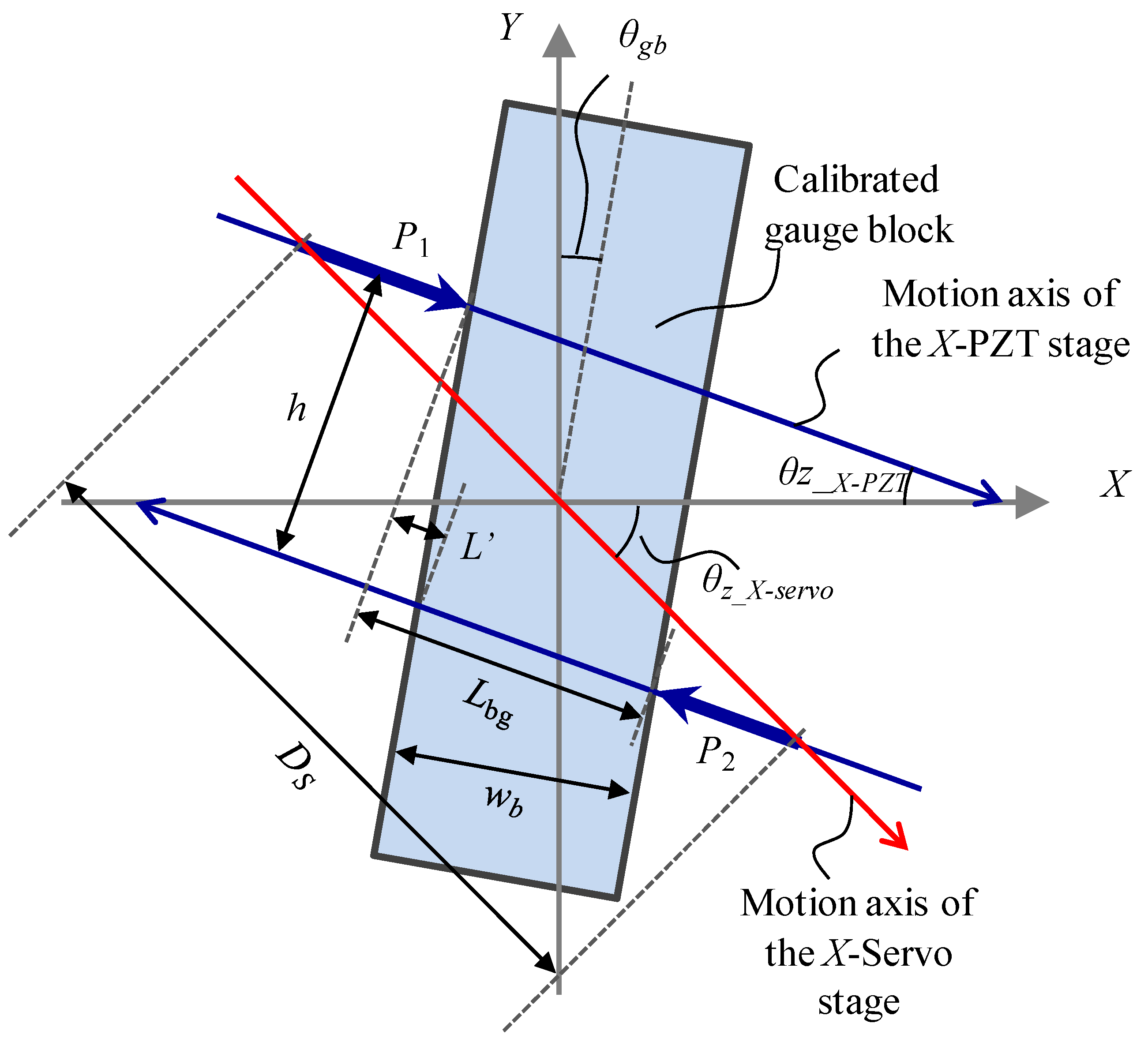
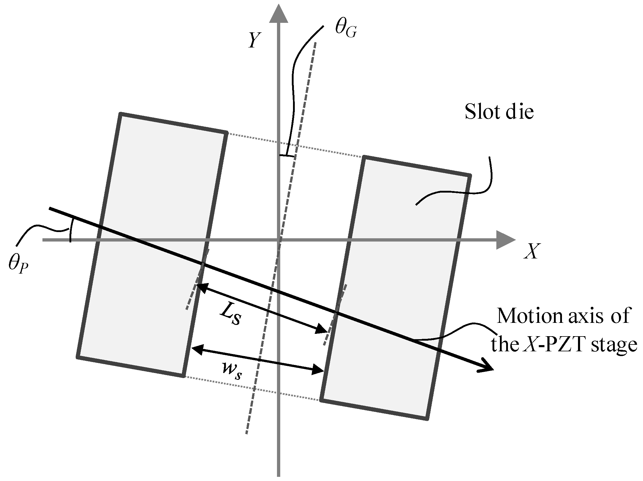
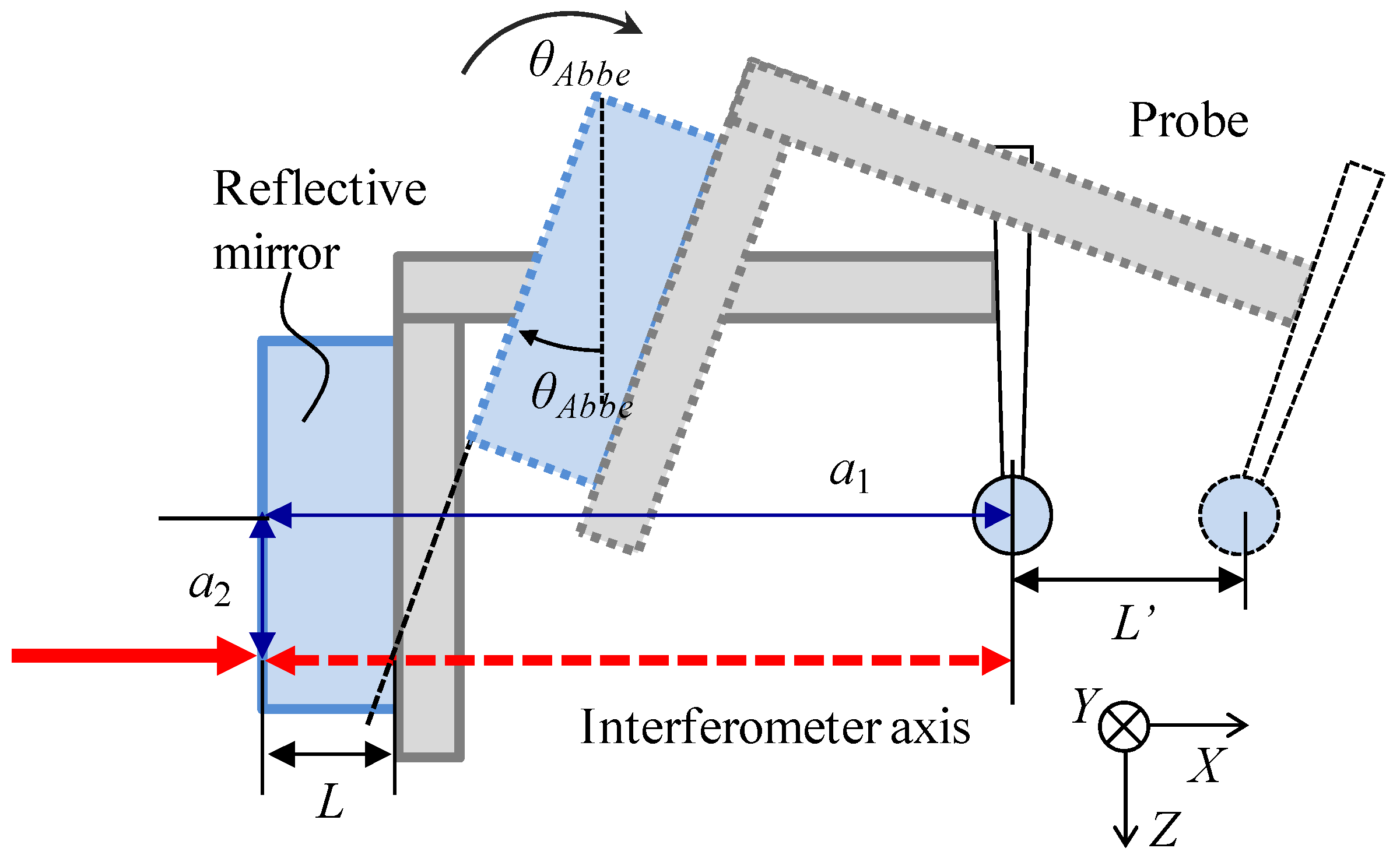
3.1. Evaluation of Alignment Errors of the Measurement System

As described above, the gap width measurement is carried out in the developed micro-CMM by probing one point on each of the surfaces of the micro-slit. The reliability of the measurement results is influenced by the angular alignment errors and motion errors of the moving stages. Figure 5 shows a schematic of the angular alignment errors of the moving stages. The moving axis of the air bearing linear slide is defined as the Y-axis. The X-axis and Z-axis are shown in Figure 5. The length direction of the micro-slit of the slot die and the surface of the gauge block are arranged in parallel with the Y-axis. The angular alignment errors of the slot die and the calibrations around the Z-axis are indicated as θgb and θsd, respectively. θgb and θsd are calculated based on the X-directional deviation ∆dx obtained by moving the Y-directional linear slide. ∆dx is measured by using an optical fiber displacement sensor with a resolution of 0.49 nm. Therefore, θgb and θsd can be calculated by using the following equations.
θ g b = tan ( Δ d x _ g b L g b )
θ s d = tan ( Δ d x _ s d L s d )
where ∆dx_gb and ∆dx_sd are the X-directional displacements of the gauge block and the slot die due to the tilt around the Z-axis of the slot die, respectively. Lgb and Lsd are the Y-directional displacements caused by the linear slide, respectively. Lgb and Lsd are set to be 180 mm and 20 mm, respectively.
The alignment errors of the X-directional moving axis of the PZT stage around the Y-axis and the Z-axis are indicated as θy_X-PZT and θy_X-PZT, respectively. Figure 6a shows a schematic diagram of the evaluated angular alignment errors of the X-directional stages. A right-angle prism mirror is placed on the table of the Y-linear slide for measurement of the deviations in the Y- and Z-directions with the optical fiber displacement sensor. The Y-Z plane of the prism mirror is aligned in parallel with the moving axis of the Y-linear slide. Based on Equations (4) and (5), θy_X-PZT and θy_X-PZT can be calculated by moving the X-directional PZT stage. Similarly, for the X-direction servo motor stages, the alignment errors around the Y-axis and Z-axis are defined as θ_X-Servo and θz_X-Servo, respectively.
The Z-directional servo motor stage is used to adjust the measurement position inside the micro-slit along the Z-direction. The alignment errors of the Z-directional servo motor stage around the X-axis and the Y-axis are indicated as θx_Z-Servo and θy_Z-Servo, respectively. As shown in Figure 6b, θx_Z-Servo and θy_Z-Servo can be evaluated by using the right-angle prism mirror and the optical fiber displacement sensor.
Figure 7 shows a schematic of the tilt errors of the reflective mirror with respect to the optical axis of the laser interferometer. Since the gap width of the micro-slit is obtained from the outputs of the laser interferometer, the alignment error of the laser interferometer is also an uncertainty source for the gap width measurement. When the reflective mirror of the interferometer, which is mounted on the opposite side of the micro-probe, is not perpendicular to the X-axis, a cosine error will occur, as shown in Figure 7. θy_mirror and θz_mirror are defined as the tilt errors around the Y- and Z-axes with respect to the optical axis, respectively. Figure 8 shows a schematic of the cosine error between the laser interferometer and X-directional moving axis. L is the distance measured by the laser interferometer. L' is the actual displacement of the probe tip along the X-direction. L'/L can be expressed by the following equation.
L L = 1 cos   θ y _ m i r r o r   cos   θ z _ m i r r o r
In order to evaluate the alignment errors of the reflective mirror with respect to the laser interferometer, the tilt errors of the reflective mirror were measured by using the optical fiber displacement probe. Figure 9 shows a schematic diagram for evaluation of the alignment errors of the reflective mirror. One plane of the right-angle prism mirror is arranged perpendicular to the X-axis of the PZT stage. The difference of the tilting angles between the prism mirror and the reflective mirror is measured. Table 1 shows a summary of the evaluated angular alignment errors of the developed micro-CMM.
Based on the evaluated alignment errors of the positioning stages, the geometric measurement errors are investigated. Figure 10 shows a geometrical model in the X-Y plane during the probing on the calibrated artifact. Lgb is the distance between the probing points on the calibrated artifact. h is the distance between the moving axes of the X-directional PZT stage on the both sides of the gauge block. Ds is the X-directional displacement of the servo motor stage. The thickness of the calibrated artifact wb can be expressed by the following equation.
w b = ( L g b L ) cos ( θ z _ X P Z T θ g b )
L' can be defined as follows.
L = h   tan ( θ z _ X P Z T θ g b )
h can be calculated by
h = D s   sin ( θ z _ X S e r v o θ z _ X P Z T )
Therefore, the measurement error ∆wb of the calibrated artifact width, which is also extended in the Y-Z plane, can be calculated by the following equation.
Δ w b = ( L g b D s ) w b = ( w b + D s   tan ( θ y _ X s e r v o θ y _ X P Z T ) tan ( θ y _ X P Z T θ g b ) cos ( θ z _ X P Z T θ g b ) w b ) + ( w b + D s   tan ( θ z _ X s e r v o θ z _ X P Z T ) tan ( θ z _ X P Z T θ g b ) cos ( θ z _ X P Z T θ g b ) w b )
Figure 11 shows a geometrical model in the X-Y plane. The measurement error ∆ws of the slit gap width can be calculated by the following equation.
Δ w s = w s cos ( θ y _ X P Z T θ y _ s d ) cos ( θ z _ X P Z T cos θ z _ s d ) w s
Since the gap width measurement is carried out by the probe displacement with the laser interferometer in the X-direction, the Abbe errors for the laser interferometer have to be considered for the evaluation of the combined standard uncertainty. When the center of the probe tip is not located on the optical axis of the laser interferometer, an Abbe error component will be caused in the measurement result of the probe displacement due to the tilt errors of the X-directional stages. Figure 12 shows the Abbe error between the probe tip and the laser interferometer. As shown in Figure 12, a1 indicates the X-directional distance between the probe tip and the reflective mirror. a2 is the Z-directional difference between the center of the probe tip and that of the laser spot on the reflective mirror. θAbbe is the tilt error of the X-directional stages. The Abbe errors Ly_Abbe and Lz_Abbe can be expressed as follows.
L y _ A b b e = ( a 1   tan θ y _ X P Z T 2 + a 2 ) tan   θ y _ X P Z T + ( a 1   tan θ y _ X S e r v o 2 + a 2 ) tan   θ y _ X S e r v o
L z _ A b b e = ( a 1   tan θ z _ X P Z T 2 + a 2 ) tan   θ z _ X P Z T + ( a 1   tan θ z _ X S e r v o 2 + a 2 ) tan   θ z _ X S e r v o
Consequently, the combined Abbe error can be expressed in the following equation.
L A b b e _ e r r o r = L y _ A b b e 2 + L z _ A b b e 2
The measurement error for the gap width measurement caused by the tilt errors of the positioning stages is then evaluated. When the probing points on the slot die surface are changed by moving the slot die with the Y-linear slide, errors will be introduced in the measurement result of the gap width by the tilt error about the Y-axis (Rolling) θslide_rolling and the tilt error about the X-axis (Yawing) θslide_yawing. The gap width measurement error ∆wy_slide caused by the tilt errors of the Y-linear slide can be indicated as follows.
Δ w y _ s l i d e = w s cos ( θ s l i d e _ r o l l i n g ) cos ( θ s l i d e _ y a w i n g ) w s
When the probing points are changed by moving the slot die with the Z-directional servo motor stage, errors will be introduced to the measurement result of the gap width by the tilt error θz-servo_rolling about the Y-axis (Rolling) and the tilt error θz-servo_pitching about the X-axis (Yawing). The gap width measurement error ∆wz-servo caused by the tilt errors of the Y-linear slide can be indicated as follows.
Δ w z s e r v o = w s cos ( θ z s e r v o _ r o l l i n g ) cos ( θ z s e r v o _ p i t c h i n g ) w s
Table 2 shows a summary of the tilt errors of the positioning stages. The tilt errors are measured by a laser autocollimator with a resolution of 1.21 μrad.
The measurement uncertainties for on-line qualification and gap width measurement can then be evaluated based on Equations (4)–(15) as well as Table 1 and Table 2.

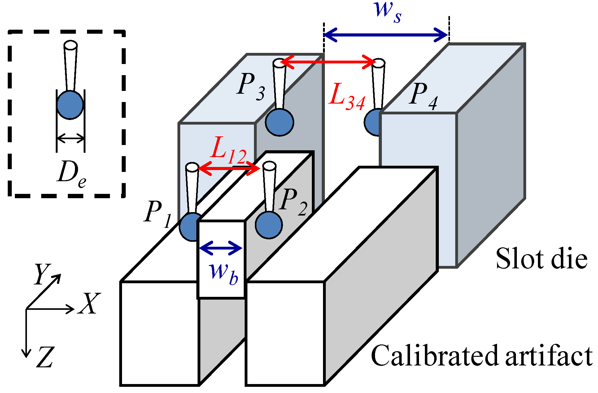
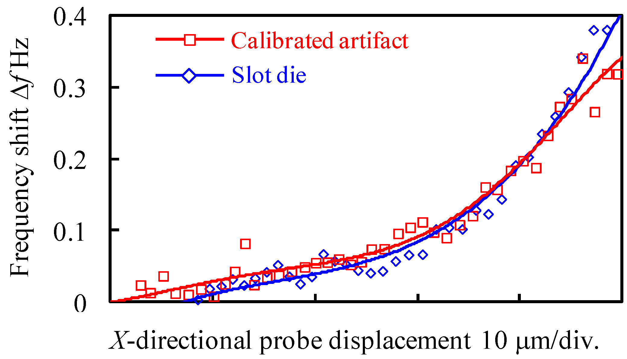
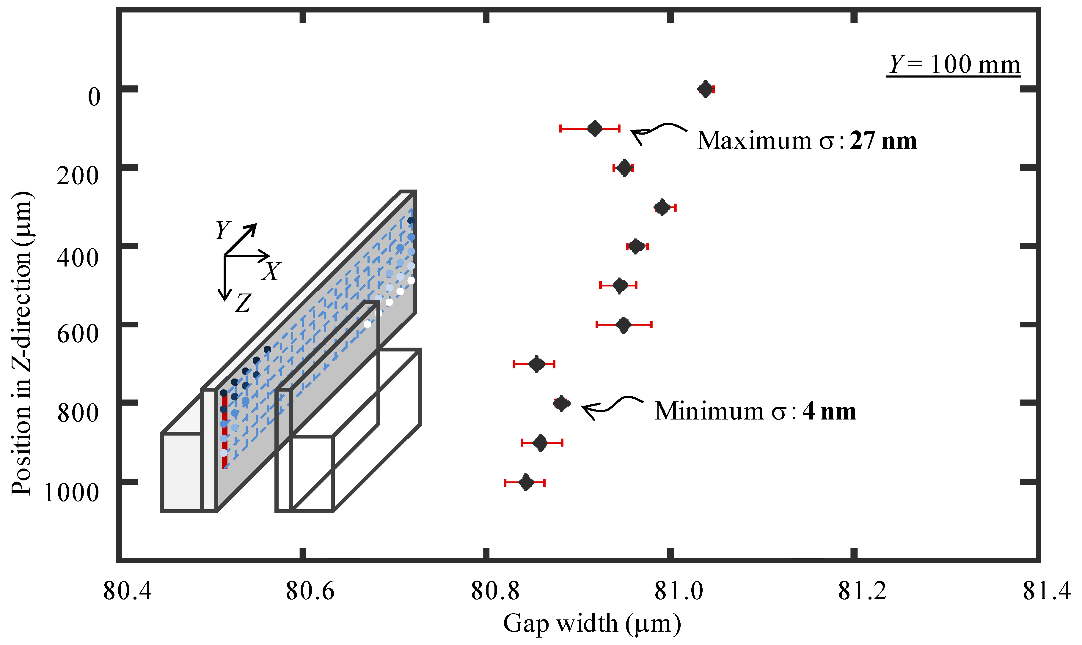
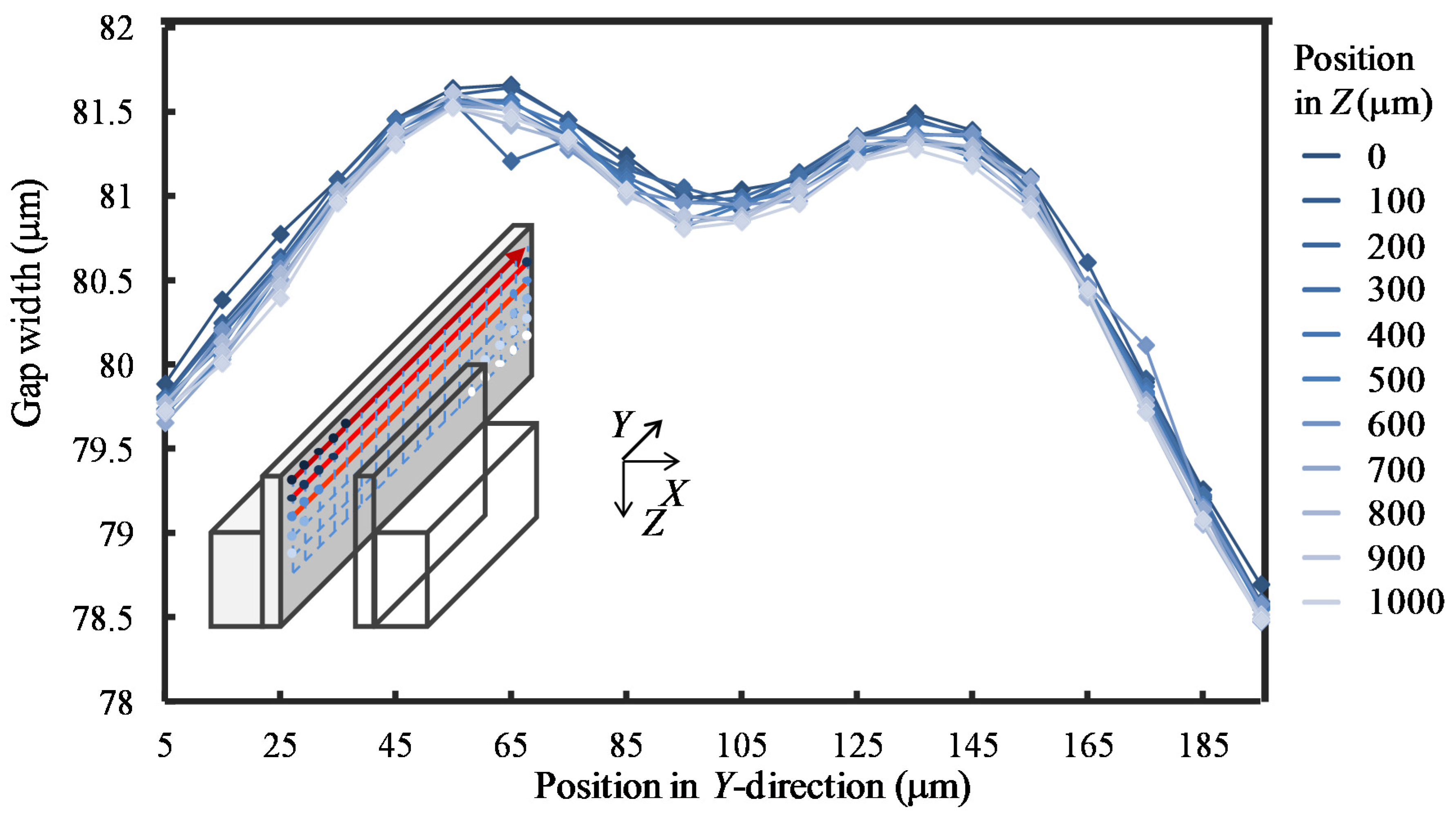
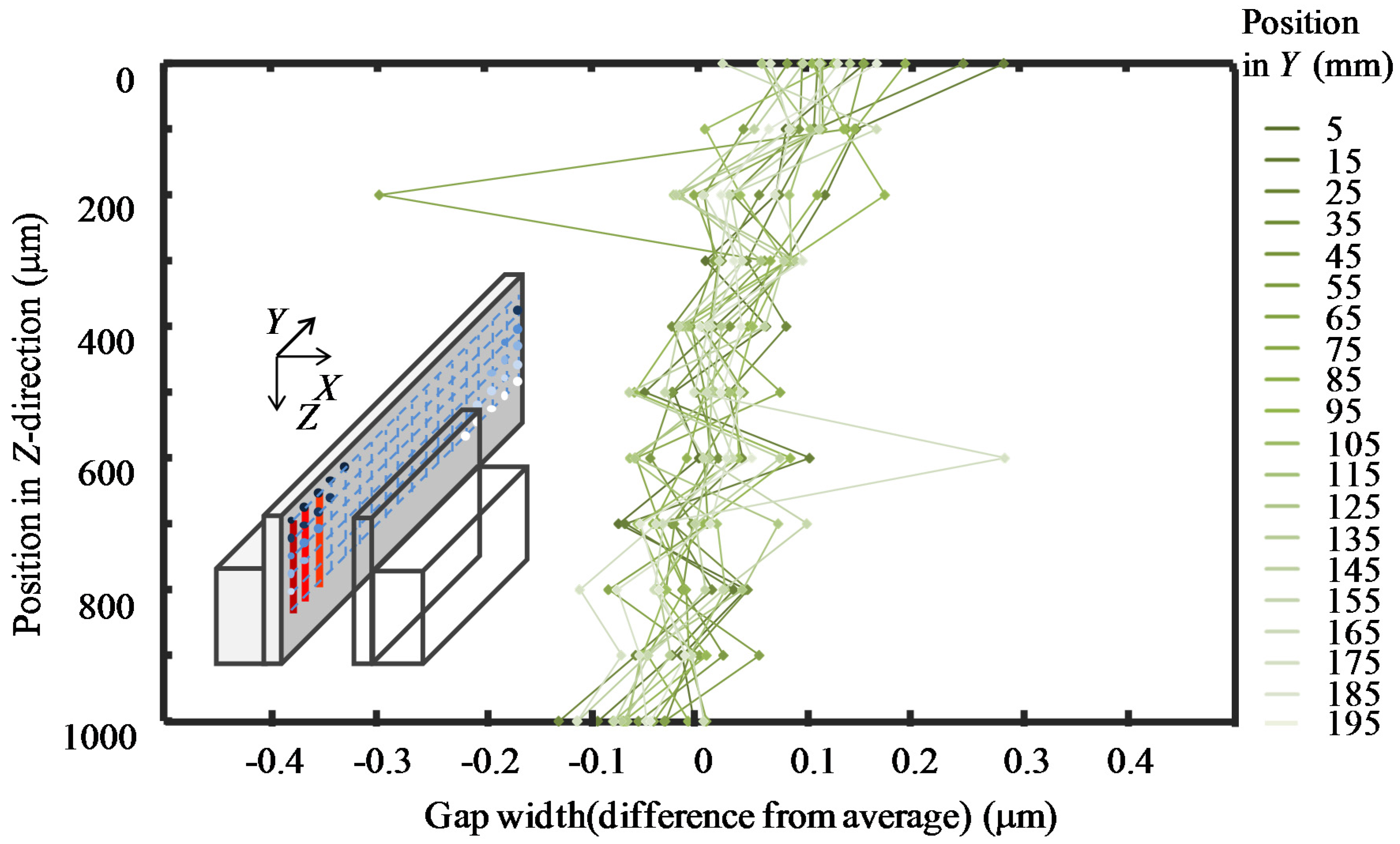
3.2. Experiments of On-Line Qualification and Gap Width Measurement

The micro-slit on the precision slot die for measurement has a nominal gap width of 85 ± 5 μm over a length of 200 mm. To avoid the influence of the chamfered edges of the precision flat parts forming the micro-slit, it is necessary for the probe tip to be arranged inside of the micro-slit for measurement of the gap width. In the developed micro-CMM, the probing position along the Z-direction is determined by utilizing the measurement capability of the shear-mode micro-probe in both the X- and Z-directions [26]. Figure 13 shows the detection strategy and the detection results of the chamfered edges of the two precision flat plates, respectively. It can be seen that the inner surfaces of the micro-slit can be identified from the measurement result shown in Figure 13b. The Z-directional height of the chamfered edges of the precision flat plates was estimated to be approximately 90 μm and the probing position along the Z-direction was selected to be lower than areas of the chamfered edges for the following experiments of on-line qualification and gap width measurement.
On-line qualification of the effective diameter of the probe tip ball was then conducted by using the calibrated artifact. As a set of the on-line qualification operation, the probe was moved to the side of P2 by the X-directional servo motor stage for another 5 times of probing at P2 after 5 times of probing at P1. It took approximately 50 s for the set of the operation. The same set of the operation was repeated 5 times to evaluate the repeatability of probing at the trigger points. Figure 14 shows the results of the on-line qualification. The X-directional positions of the trigger points at P1 and P2, which is a contact points between the probe tip ball and the inside surface of the slot die, are shown in Figure 14a,b, respectively. The vertical axes shown in Figure 14a,b show the X-directional probing positions calculated by the output of the laser interferometer. The mean values of the X-directional positions of the trigger points at P1 and P2 over the 5 sets of on-line qualification operations were 5.625 μm and 159.344 μm, respectively. Due to the thermal drift between the laser interferometer and the reflective mirror mounted on the X-PZT stage, the mean values at P1 and P2 were changed almost linearly due to the influence of thermal drifts. Figure 14c shows the value of L12 calculated by taking the difference of the corresponding results of Figure 14a,b, in which the thermal drift error components were removed. The mean and the standard deviation of L12 over the 5 sets of on-line qualification were 153.781 μm and 11.5 nm, respectively. Consequently, the effective diameter of the probe tip ball De was estimated to be 53.781 μm.
After the on-line qualification, the probing position was located to the inside of the micro-slit by moving the slot die with the Y-linear slide for the gap width measurement. At each Y-directional measurement position, after the probing at P3, the probe was moved by the X-directional PZT stage toward the opposite surface of the micro-slit for the probing at P4. This operation was repeated 5 times. The results are shown in Figure 15. Figure 15a,b show the probing positions at P3 and P4, which indicate the X-directional probe contact positions at the inner surface of the slot die. The mean values at P3 and P4 are −13.392 μm and 13.865 μm, respectively. Figure 15c shows the values of L34 calculated based on the results in Figure 15a,b. The mean and the standard deviation of L34 were estimated to be 27.243 μm and 14.8 nm, respectively. According to Equation (3), the gap width of the slot die micro-slit was estimated to be 80.962 μm.
In order to evaluate the accuracy of the gap width measurement result, uncertainty analysis was carried out for each of the terms in Equation (3) based on GUM (ISO Guide to the Expression of Uncertainty in Measurement) [33]. Table 3 shows a summary of the uncertainty budget for the gap width measurement. uws, which was the combined standard uncertainty of L34, is calculated based on Figure 11, Equations (11) and (14). The repeatability of probing was one of the main uncertainty sources for uws. The total time for the gap width measurement was approximately 90 s, during which the temperature was measured to be 22.677 °C ± 0.011 °C. Consequently, uws is estimated to be 10.5 nm, which corresponds to the combined standard uncertainty for the measurement of L34.
uDe, which was the combined standard uncertainty of the on-line qualification of the effective diameter of the probe tip ball, was estimated based on Figure 10, Equations (10) and (14). As shown in Table 3, the cosine error caused by the misalignment of the gauge block and the probing axis was a relatively large uncertainty source because the X-directional servo stage was moved during the on-line qualification process. The total time for the on-line qualification of the effective diameter was approximately 250 s, during which the temperature was measured to be 22.677 °C ± 0.008 °C. As a result, uDe was estimated to be 26.4 nm. uwb was the length tolerance of the calibrated gauge block. According to the calibration certification of the gauge block used in the micro-CMM, uwb was estimated to be 17.3 nm. us was the uncertainty source introduced by the water layer on the measured surface. It was estimated to be 1.2 nm, based on Figure 4. Consequently, the expanded uncertainty U of the gap width measurement was estimated to be 66.6 nm (k = 2), which was smaller than the allowed maximum expanded uncertainty of 100 nm.
By changing the probing position along the Y- and Z-directions, the gap width uniformity was measured. Figure 16 shows the gap widths at measurement positions with an equal interval of 10 mm along the Y-direction. The measurement depth was set to be 50 μm. The probing was repeated 3 times at each measurement position. The dot plot in the figure shows the mean value of the repeated probing results and the error bar represents the corresponding standard deviation at each measurement position. The maximum and minimum values of the measured gap widths along the Y-direction were 78.883 μm and 81.980 μm, respectively. The total measurement time was approximately 1800 s. Since the two precision flat plates of the slot die were fastened by the screws at the center and the two ends of the slot die, the gap width tended to be smaller at the positions of the screws, which was corresponding to the measurement results in Figure 16. The maximum and minimum standard deviations of the measured gap widths were 27 nm and 4 nm, respectively. The employment of the long stroke air-bearing linear slide made it possible for measurement of the gap width uniformity over the entire slot die length of 200 mm, which was a significant improvement on a conventional micro-CMM.
Figure 17 shows the measured gap widths at the measurement positions with an equal interval of 100 μm along the Z-direction. The measurements were carried out at Y = 100 mm. The probing was repeated 5 times at each measurement position. The dot plot in the figure shows the mean value of the repeated probing results and the error bar represents the corresponding standard deviation at each measurement position. The maximum and minimum standard deviations of the measured gap widths were 27 nm and 4 nm, respectively. The total measurement time was approximately 990 s. The gap widths along the Z-direction were almost uniform. It can be seen from the figure that the gap width was successfully measured at Z = 1000 μm, indicating the effective working distance of the developed micro-CMM along the Z-direction.
The gap widths along different Y-directional lines were measured by changing the measurement depths along the Z-direction. The interval between the measurement points along the Y-direction was 10 mm and that along the Z-direction was 100 μm. The total number of probing points was 220. During the measurement, the temperature was measured to be 24.1 ± 0.1 °C. The total measurement time was approximately 200 min. As can be seen in Figure 18, the gap widths along different Y-lines were quite similar to each other. The measured gap widths at the same Y-position but different Z-positions were employed to demonstrate the gap widths at different Z-lines. The results are shown in Figure 19. It can be seen that the gap width slightly decreased with the increase in the measurement depth for all the Z-lines.

4. Conclusions

Dimensional measurement of micro-slit gap width of a precision slot die coater with a length of 200 mm and a nominal width of 85 μm has been carried out by using a specially designed and constructed micro-CMM. A shear-mode micro-probing system was employed in the micro-CMM. A calibrated artifact, which was a calibrated gauge block with a thickness of 100 μm, was placed on the same stage table as a Y-directional linear slide for the on-line qualification of the effective diameter of the probe tip ball prior to the gap width measurement of the slot die. The proposed micro-CMM, which combined the micro-probing system and a laser interferometer, was able to achieve nanometric resolution and repeatability of length measurement. The effective diameter De of the probe tip ball was evaluated to be 53.781 μm, and the expanded uncertainty in De was estimated to be 52.8 nm (k = 2). After the qualification procedure, the gap width measurement of the slot die was carried out immediately. As a result, the expanded uncertainty of the gap width measurement was estimated to be 66.6 nm (k = 2), which can satisfy the required measurement accuracy. The use of an air-bearing linear slide with a stroke of 300 mm has made it possible for the micro-CMM to cover the entire length of the precision slot die. Furthermore, a micro-stylus with an effective working length of larger than 1 mm, which was composed of a capillary glass shaft and a micro-glass sphere, has been employed to measure the gap width from the inside of the micro-slit of the precision slot die.
On the other hand, the shear-mode micro-probe was utilized as a touch-trigger probe in the developed micro-CMM and the total measurement time for the uniformity evaluation of the gap width was approximately 200 min. Reduction of the measurement time will be an important future work.

Acknowledgments

This research was supported by KAKENHI. The authors would like to acknowledge the Ministry of Education, Culture, Sports, Science and Technology (MEXT) and Japan Society for the Promotion of Science (JSPS).

Author Contributions

S.I. and W.G. conceived the experiments and wrote the paper; H.K. designed the experimental apparatus and performed the experiment; Y.C and Y.S. analyzed the data. K.T., T.K., K.A. and A.H. contributed to prepare slot die sample.

Conflicts of Interest

The authors declare no conflict of interest.

References

  1. Chen, Y.L.; Gao, W.; Ju, B.F.; Shimizu, Y.; Ito, S. A measurement method of cutting tool position for relay fabrication of microstructured surface. Meas. Sci. Technol. 2014, 25, 064018. [Google Scholar] [CrossRef]
  2. Aziz, M.; Ohnishi, O.; Onikura, H. Novel micro deep drilling using micro long flat drill with ultrasonic vibration. Precis. Eng. 2012, 36, 168–174. [Google Scholar] [CrossRef]
  3. Hao, T.; Yong, L.; Long, Z.; Baoquan, L. Mechanism design and process control of micro EDM for drilling spray holes of diesel injector nozzles. Precis. Eng. 2013, 37, 213–221. [Google Scholar]
  4. Goda, J.; Mitsui, K. Development of an integrated apparatus of micro-EDM and micro-CMM. Measurement 2013, 46, 552–562. [Google Scholar] [CrossRef]
  5. Vala, M.; Homola, J. Flexible method based on four-beam interference lithography for fabrication of large areas of perfectly periodic plasmonic arrays. Opt. Express 2014, 22, 18779–18789. [Google Scholar] [CrossRef] [PubMed]
  6. Meijer, T.; Beardmore, J.P.; Fabrie, C.G.C.H.M.; Lieshout, J.P.; Notermans, R.P.M.J.W.; Sang, R.T. Structure formation in atom lithography using geometric collimation. Appl. Phys. B 2011, 105, 703–713. [Google Scholar] [CrossRef]
  7. Chou, S.Y.; Krauss, P.R.; Renstrom, P.J. Nanoimprint lithography. J. Vacuum Sci. Technol. B 1996, 14, 4129–4133. [Google Scholar] [CrossRef]
  8. Heckele, M.; Schomburg, W.K. Review on micro molding of thermoplastic polymers. J. Micromech. Microeng. 2004, 14, R1–R14. [Google Scholar] [CrossRef]
  9. Bos, E.J.C. Aspects of tactile probing on the micro scale. Precis. Eng. 2011, 35, 228–240. [Google Scholar] [CrossRef]
  10. Haitjema, H.; Pri, W.O.; Schellekens, P.H.J. Development of a Silicon-based Nanoprobe System for 3-D Measurements. CIRP Ann. Manuf. Technol. 2001, 50, 365–368. [Google Scholar] [CrossRef]
  11. Cui, J.; Li, J.; Feng, K.; Tan, T. Three-dimensional fiber probe based on orthogonal micro focal-length collimation for the measurement of micro parts. Opt. Express 2015, 23, 26386–26398. [Google Scholar] [CrossRef] [PubMed]
  12. Muralikrishnan, V.; Stone, J.; Shakarji, C.; Stoup, J. Performing three-dimensional measurements on micro-scale features using a flexible coordinate measuring machine fiber probe with ellipsoidal tip. Meas. Sci. Technol. 2012, 23, 025002. [Google Scholar] [CrossRef]
  13. Fan1, K.C.; Fei, Y.T.; Yu, X.F.; Chen, Y.J.; Wang, W.L.; Chen, F.; Liu, Y.S. Development of a low-cost micro-CMM for 3D micro/nano measurements. Meas. Sci. Technol. 2006, 17, 524–532. [Google Scholar] [CrossRef]
  14. Schwenke, H.; Waldele, F.; Weiskirch, C.; Kunzmann, H. Opto-tactile Sensor for 2D and 3D Measurement of Small Structures on Coordinate Measuring Machines. CIRP Ann. Manuf. Technol. 2001, 50, 361–364. [Google Scholar] [CrossRef]
  15. Michihata, M.; Hayashi, T.; Adachi, A.; Takaya, Y. Measurement of Probe-stylus Sphere Diameter for Micro-CMM Based on Spectral Fingerprint of Whispering Gallery Modes. CIRP Ann. Manuf. Technol. 2014, 63, 469–472. [Google Scholar] [CrossRef]
  16. Takaya, Y.; Shimizu, H.; Takahashi, S.; Miyoshi, T. Fundamental study on the new probe technique for the nano-CMM based on the laser trapping and Mirau interferometer. Measurement 1999, 25, 9–18. [Google Scholar] [CrossRef]
  17. Masuzawa, T.; Harnasaki, Y.; Fujino, M. Vibroscanning Method for Nondestructive easurement of Small Holes. CIRP Ann. Manuf. Technol. 1993, 42, 589–592. [Google Scholar] [CrossRef]
  18. Kim, B.J.; Masuzawa, T.; Bourouina, T. The vibroscanning method for the measurement of micro-hole profiles. Meas. Sci. Technol. 1999, 10, 697–705. [Google Scholar] [CrossRef]
  19. Weckenmann, A.; Hoffmann, J.; Schuler, A. Development of a tunnelling current sensor for a long-range nano-positioning device. Meas. Sci. Technol. 2008, 19, 064002. [Google Scholar] [CrossRef]
  20. Bauza, M.B.; Hocken, R.J.; Smith, S.T.; Woody, S.C. Development of a virtual probe tip with an application to high aspect ratio microscale features. Rev. Sci. Instrum. 2015, 76, 095112. [Google Scholar] [CrossRef]
  21. Bauza, M.B.; Woody, S.C.; Woody, B.A.; Smith, S.T. Surface profilometry of high aspect ratio features. Wear 2011, 271, 519–522. [Google Scholar] [CrossRef]
  22. Claverley, J.D.; Leach, R.K. Development of a three-dimensional vibrating tactile probe for miniature CMMs. Precis. Eng. 2013, 37, 491–499. [Google Scholar] [CrossRef]
  23. Leach, R.K.; Claverley, J.; Giusca, C.; Jones, C.W.; Nimishakavi, L.; Sun, W.; Tedaldi, M.; Yacoot, A. Advances in engineering nanometrology at the National Physical Laboratory. Meas. Sci. Technol. 2012, 23, 074002. [Google Scholar] [CrossRef]
  24. Murakami, H.; Katsuki, H.; Sajima, T.; Suematsu, T. Study of a vibrating fiber probing system for 3-D micro-structures: Performance improvement. Meas. Sci. Technol. 2014, 25, 094010. [Google Scholar] [CrossRef]
  25. Murakami, H.; Katsuki, A.; Onikura, H.; Sajima, T.; Kawagoshi, N.; Kondo, E. Development of a System for Measuring Micro Hole Accuracy Using an Optical Fiber Probe. J. Adv. Mech. Des. Syst. Manuf. 2010, 4, 995–1004. [Google Scholar] [CrossRef]
  26. Ito, S.; Kodama, I.; Gao, G. Development of a probing system for a micro-coordinate measuring machine by utilizing shear-force detection. Meas. Sci. Technol. 2014, 25, 064011. [Google Scholar] [CrossRef]
  27. Manning, B. The Use of Non-Contact Thin Gap Sensors in Controlling Coater Gap Uniformity; Capacitec, Inc.: Ayer, MA, USA, 2012. [Google Scholar]
  28. Furukawa, M.; Gao, W.; Shimizu, H.; Kiyono, S.; Yasutake, M.; Takahashi, K. Slit width measurement of a long precision slot die. J. Jpn. Soc. Precis. Eng. 2003, 69, 1013–1017. [Google Scholar] [CrossRef]
  29. Claverley, J.D.; Leach, R.K. A review of the existing performance verification infrastructure for micro-CMMs. Precis. Eng. 2015, 39, 1–15. [Google Scholar] [CrossRef]
  30. Muralikrishnan, B.; Stone, J.A.; Stoup, J.R. Fiber deflection probe for small hole metrology. Precis. Eng. 2006, 30, 154–164. [Google Scholar] [CrossRef]
  31. Thermo Scientific. Available online: http://www.thermoscientific.com/en/product/ (accessed on 5 May 2016).
  32. Ito, S.; Chen, Y.L.; Shimizu, Y.; Kikuchi, H.; Gao, W.; Takahashi, K.; Kanayama, T.; Arakawa, K.; Hayashi, A. Uncertainty analysis of slot die coater gap width measurement by using a shear mode micro-probing system. Precis. Eng. 2016, 43, 525–529. [Google Scholar] [CrossRef]
  33. Working Group 1 of the Joint Committee for Guides in Metrology (JCGM/WG1). JCGM 100. In Evaluation of Measurement Data—Guide to the Expression of Uncertainty in Measurement (GUM); Bureau International des Poids et Mesures: Paris, France, 2008. [Google Scholar]
Figure 1. Configuration of shear-mode micro-probe. (a) Photograph of shear-mode micro-probe; (b) Schematic diagram of shear-mode micro-probe.
Applsci 06 00156 g001
Figure 2. Experimental configuration of the micro-CMM (micro-coordinate measurement machine) by using a shear-mode micro-probe.
Applsci 06 00156 g002
Figure 3. Schematic diagram of on-line qualification and length measurement of gap width.
Applsci 06 00156 g003
Figure 4. Vibration frequency shifts when probing the calibrated artifact and the slot die.
Applsci 06 00156 g004
Figure 5. Schematic of the angular alignment errors of the moving axes of the measurement system.
Applsci 06 00156 g005
Figure 6. Schematic for evaluation of the angular alignment errors: (a) X-directional stages; (b) Z-directional stage.
Applsci 06 00156 g006
Figure 7. Tilt errors of the reflective mirror with respect to the optical axis of the laser interferometer.
Applsci 06 00156 g007
Figure 8. Schematic of the cosine error between the laser interferometer and the X-directional moving axis.
Applsci 06 00156 g008
Figure 9. Schematic of angular alignment errors evaluation of the reflective mirror of the laser interferometer.
Applsci 06 00156 g009
Figure 10. Geometrical model of the alignment error of the probing points during the qualification procedure.
Applsci 06 00156 g010
Figure 11. Geometrical model of the alignment error of the probing points during the gap width measurement.
Applsci 06 00156 g011
Figure 12. Schematic of Abbe error caused by the tilting motion of X-directional moving stage.
Applsci 06 00156 g012
Figure 13. Chamfered edge detection by using the micro-probe: (a) Detection strategy of the chamfered edge; (b) Measurement result of the slit position.
Applsci 06 00156 g013
Figure 14. Experimental results of on-line qualification procedure: (a) Probing results at P2; (b) Probing results at P1; (c) Measurement results of L12.
Applsci 06 00156 g014
Figure 15. Experimental results of gap width measurement: (a) Probing results at P4; (b) Probing results at P3; (c) Measurement results of L34.
Applsci 06 00156 g015
Figure 16. Measurement results of gap uniformity of slot die along the Y-direction.
Applsci 06 00156 g016
Figure 17. Measurement results of gap uniformity of slot die along the Z-direction.
Applsci 06 00156 g017
Figure 18. Gap width uniformity over the entire slot die length (Y-direction).
Applsci 06 00156 g018
Figure 19. Gap width uniformity over the entire slot die length (Z-direction).
Applsci 06 00156 g019
Table 1. Summary of the angular alignment errors of the positioning stages.
θy_X-PZTθz_X-PZTθy_X-Servoθz_X-Servoθx_Z-Servo
7.5 mrad2.8 mrad14.0 mrad3.6 mrad5.7 mrad
θy_Z-ServoθSlotdieθGauge-blockθy_mirrorθz_mirror
14.1 mrad0.03 mrad0.07 mrad6.8 mrad0.34 mrad
Table 2. Summary of tilting errors of the positioning stages.
StageAxisStrokeTilting Error
Y-linear slideRolling300 mm8.10 mrad
Yawing12.31 mrad
Z-servo motorRolling1 mm22.59 mrad
Pitching73.40 mrad
Table 3. Uncertainty budget (unit: nm).
Uncertainty sourcesSymbolValueCoverage FactorStandard Uncertainty
Uncertainty in wSuws--10.5
Cosine error by the alignment of the gauge block and the probing axisucos_slotdie2.6 3 1.7
Cosine error by the alignment of the interferometer axis and the probing axisucos_laser0.6 3 0.3
Abbe error of the X-PZT stageupzt_abbe5.27 3 3.0
Resolution of the interferometerulaser_resolution0.79 3 0.5
Linearity error of the interferometerulaser_linearity5.0 3 2.9
Thermal drift by temperature changeuThermal_drift7.0 3 4.0
Repeatability of L34urep_L3414.8 3 8.5
Uncertainty in DeuDe--26.4
Cosine error by the alignment of the gauge block and the probing axisucos_gauge11.0 3 6.4
Cosine error by the alignment of the interferometer axis and the probing axisucos_laser3.58 3 2.1
Abbe error of the X-PZT stageupzt_abbe5.27 3 3.0
Abbe error of the X-servo stageuservo_abbe41.5 3 24.0
Resolution of the interferometerulaser_resolution0.79 3 0.5
Linearity error of the interferometerulaser_linearity5.0 3 2.9
Thermal drift by temperature changeuThermal_drift7.0 3 4.0
Repeatability of L12urep_L1211.5 3 6.6
Uncertainty in wbuwb--17.3
Length tolerance(Calibrated gauge block)utol_calibrate20.0 3 17.3
Uncertainty in Dsus--1.2
Uncertainty due to water layeruwater2.0 3 1.2
Expanded uncertainty (with a coverage factor k = 2)U--66.6

