Investigation of Physical Phenomena and Cutting Efficiency for Laser Cutting on Anode for Li-Ion Batteries


Department of Mechanical and Automotive Engineering, Kongju National University, Cheonan 31080, Korea
Appl. Sci. 2018, 8(2), 266; https://0-doi-org.brum.beds.ac.uk/10.3390/app8020266
Submission received: 12 December 2017
/
Revised: 1 February 2018
/
Accepted: 6 February 2018
/
Published: 11 February 2018
(This article belongs to the Special Issue Advanced Materials for Rechargeable Lithium Batteries)
Abstract
:Lithium-ion batteries have a higher energy density than other secondary batteries. Among the lithium-ion battery manufacturing process, electrode cutting is one of the most important processes since poor cut quality leads to performance degradation, separator protrusion, and local electric stress concentration. This may, eventually, lead to malfunction of lithium-ion batteries or explosion. The current mechanical cutting technology uses a contact process and this may lead to process instability. Furthermore, there are additional costs if the tools and cell design are changed. To solve these issues, laser cutting has been used. Conventional dependent parameters have limitations in investigating and explaining many physical phenomena during the laser cutting of electrodes. Therefore, this study proposes specific widths such as melting, top, and kerf width. Moreover, the relationship between laser parameters and multiphysical phenomena with the proposed widths are investigated. Five types of classification with regard to physical phenomena are presented and explained with SEM images. Cutting efficiency is estimated with the proposed widths. The proposed specific cutting widths, five types of geometrical classification, and cutting efficiency can be used as standardized parameters to evaluate the cutting quality.
1. Introduction
Lithium-ion batteries, which are secondary rechargeable batteries, have a higher energy density than other secondary batteries such as Ni–Cd batteries and Pd batteries if compared under the same conditions. Therefore, they can be used for energy storage devices, electronic devices, and electric vehicles, and demand for them has increased significantly [1]. The lithium-ion manufacturing process can be categorized into two parts: (1) electrode coating and (2) cell assembly [2]. During this manufacturing process, electrode cutting is one of the most important processes since poor cut quality leads to performance degradation. Moreover, defects such as burr and dross result in separator protrusion and local electric stress concentration. This may, eventually, lead to malfunction of lithium-ion batteries or explosion [3]. Currently, die cutting or rotary knife cutting is used to cut electrodes. Since this process is a contact process, tools can be worn out and process instability can be observed with high possibility. Hence, this process instability has more chance to result in poor cut quality with defects such as burr and delamination. Furthermore, the lack of a standardized battery cell design leads to frequent changes in manufacturing specification, whenever the cell design is changed. Therefore, these frequent tool and design changes cause unexpected additional manufacturing cost. These disadvantages observed with current manufacturing methods can be improved by a laser cutting process due to its many advantages, such as being a noncontact process, with a high energy concentration, fast processing time, and higher flexibility for manufacturing design change.
Laser cutting has been applied with high popularity compared to other laser-aided manufacturing processes [4,5,6,7,8,9]. Recently, laser cutting was applied to cut electrodes of lithium-ion batteries [10]. The first laser technology using cost-efficient nanosecond laser cutting of electrodes was applied and successfully transferred to industry [10]. Lee et al. [2,11,12,13,14,15,16,17,18,19,20] investigated physical phenomena during laser electrode cutting theoretically and experimentally with a continuous single-mode fiber laser. Lutely et al. [21,22] used a continuous(CW) and pulsed laser to cut lithium iron phosphate battery electrodes. They characterized the process efficiency and quality. They found that the cutting efficiency increases with shorter pulses, higher velocity, and shorter wavelength. Luetke et al. [23] investigated a comparative study on cutting electrodes for lithium-ion batteries with lasers. They compared a CW and pulsed laser to evaluate the cut quality by defining frazzling and clearance widths. They concluded that due to the high power range of the CW laser cutting system, it is advantageous in terms of cutting speed. In addition, the pulsed laser cutting system provides more opportunities for further improvements of the cutting quality. Demir et al. [24] compared the cut quality of laser cutting of lithium-ion electrodes with green (λ = 532 nm, τ = 1 ns) and infrared (λ = 1064 nm, τ = 250 ns) pulsed lasers. They found that the green laser provided a clearance width below 20 μm. In addition, the infrared laser met the high-productivity criterion with laser power of 54 W and a cutting speed of 30 m/min.
While many physical phenomena occur during laser cutting, conventional parameters have been still used for the analysis of laser cutting, such as kerf width and penetration depth. Therefore, this study proposes specific parameters such as melting width, top width, and kerf width to analyze multiphysical phenomena more intuitively during the laser cutting of electrodes in addition to the conventional parameters. Moreover, the relationship between laser parameters and multiphysical phenomena with the proposed specific widths are investigated with cutting efficiency. This study is composed as follows. First, experimental setup and material used are explained. Second, the analysis of the cutting efficiency is explained. Third, the specific widths for the analysis of multiphysical phenomena are proposed. Further, the relationship between the laser parameters and the proposed specific parameters is discussed. Finally, the conclusions are presented.
2. Experimental Setup and Materials
The experimental setup can be found in Lee et al. [25]. A single-mode Quasi-Continuous Ytterbium Fiber laser (IPG YLM-200/2000-QCW) was used in a continuous mode with a wavelength of 1070 nm. Its M2 value was 1.05. The maximum average laser power was 250 W. The total thickness of the workpiece was 50 μm and an active electrode material was coated on a current collector with a thickness of 30 μm. The material of the active electrode was 90% graphite and 10% Polyvinylidene fluoride, which was used as a binder. The current collector material was a copper foil. The workpiece was placed on the flat plate and fixed at the end of the workpiece. The distance between the workpiece and the F-theta lens was 100 mm. The laser spot size was 23 μm. The laser parameters chosen were laser power and laser scanning speed since these play a major role during laser cutting. The laser power was varied from 50 W to 250 W with in steps of 50 W. The laser scanning speed was varied from 500 mm/s to 5000 mm/s in steps of 500 mm/s. The laser parameters used for the experiments are tabulated in Table 1 with a line energy.
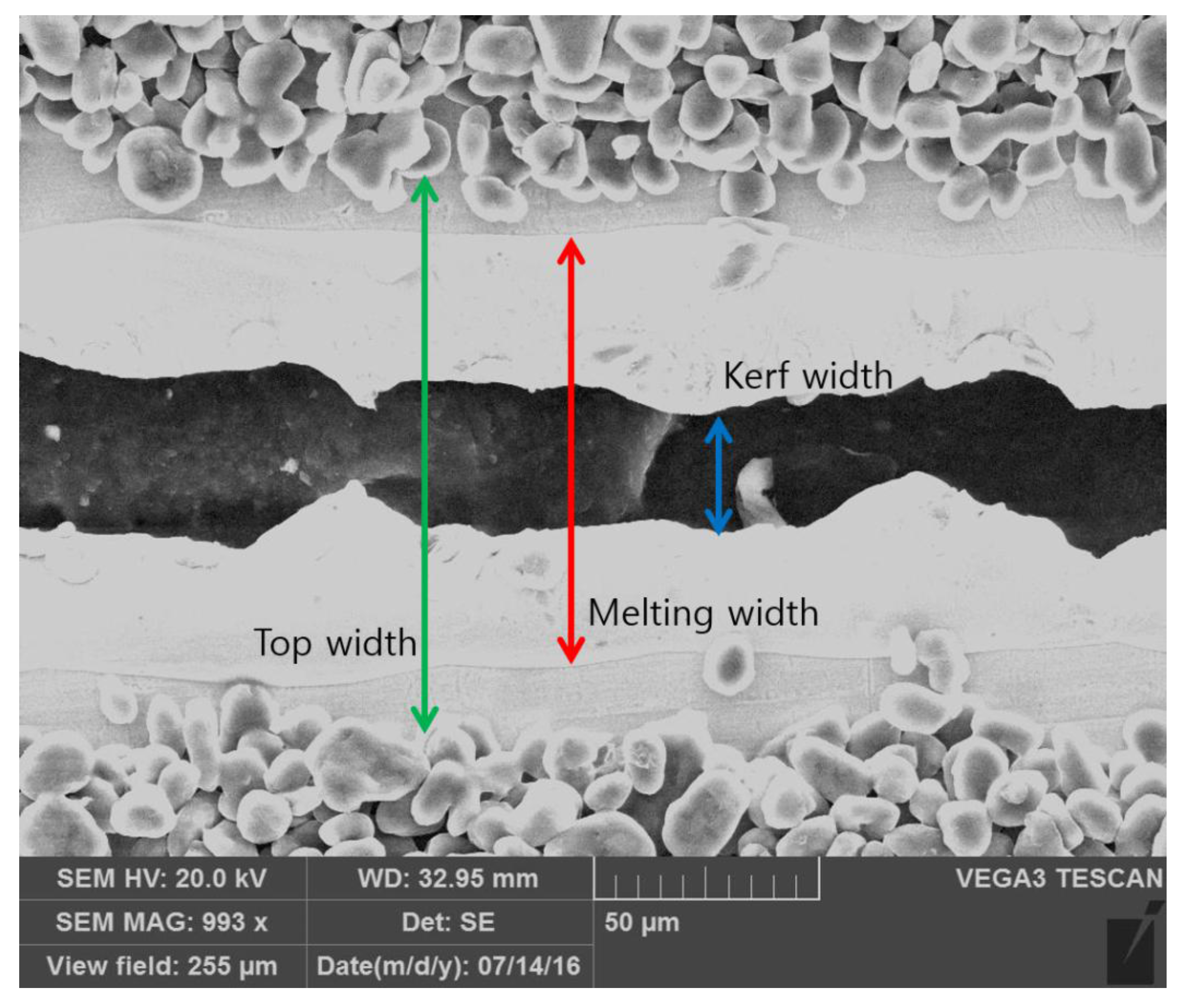
To observe the physical phenomena during laser cutting of the electrodes, Scanning Electron Microscopy (SEM) was used. The specific parameters for the analysis of physical phenomena are defined in Figure 1 for the anode. The top width () is defined by the width of the active electrode material removed by the laser, the melting width () is defined by the width of the current collector with melting marks, and the kerf width () is defined as the fully removed width.
3. Analysis of Processing Efficiency
The heat transfer efficiency () [26] is the efficiency of energy transmission from the source to the workpiece and defined as
where is power actually absorbed by the workpiece and is total power available at the laser source. The processing efficiency () is the thermal efficiency of energy conversion in the workpiece and defined as
where is the power required to melt, evaporate, and thus remove a given volume of material. From the measured widths and geometrical information, the power required to remove the material can be estimated. In addition, the total laser power available at the laser source is also estimated. Therefore, these efficiencies can be combined as
Since there is no clear definition of this term, this term is named as the cutting efficiency (). Hence, first, the assumptions required to use the cutting efficiency need to be explained. Furthermore, the power required to melt, evaporate, and remove a given volume of material, as well as the total power available at the laser source, needs to be calculated.
3.1. Assumptions
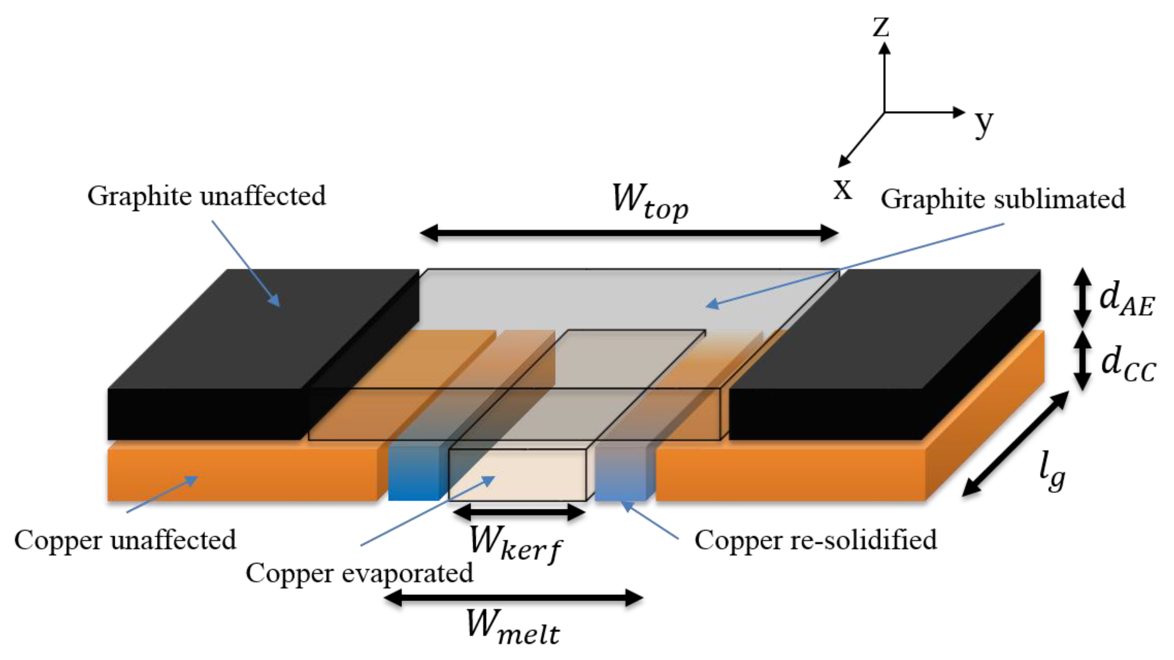
The geometrical assumption is shown in Figure 2. For simplicity, several rectangular parallelepipeds were assumed to express the material deformed by sublimation, melting, and evaporation. Since the cutting efficiency is estimated not during the laser cutting but after the laser cutting, no melting flow, boiling, or plasma formation was considered. A Gaussian laser beam distribution was assumed. The beam profile and radius do not change in the z-direction.
3.2. Laser Power Input (
Laser intensity distribution can be expressed by a combination of a Gaussian beam profile and a Laguerre polynomial [15]. This expression can be written as
where is the laser intensity, is a parameter related to the laser beam radius () and distance from the heat source, and is the angle between the reference direction on the chosen plane. The laser beam radius, which is one half of the beam diameter, was set to 11.5 μm in this study. The line from the origin, , is the radial distance, and is the associated Laguerre polynomial of order and index . The Laguerre polynomial is expressed as
From Equations (4) and (5), the laser power can be obtained and expressed as
From Equation (4), when and , the Gaussian distribution can be expressed as
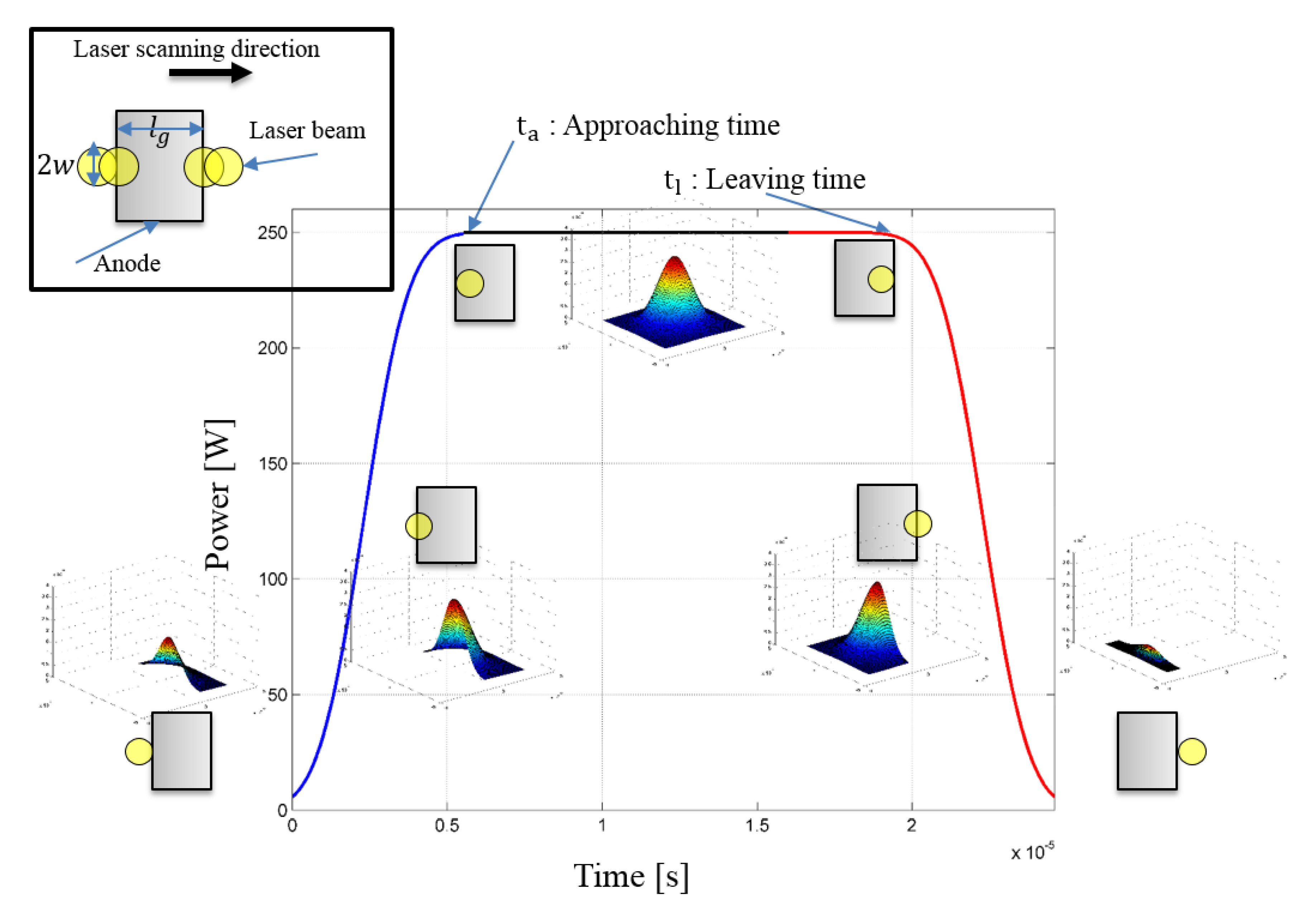
where is a given laser power by a laser cutting system. Even though the laser power is given by the system, the real laser energy irradiated on the material surface could be different. Therefore, this study calculated a more precise laser power considering its approaching and leaving time. Laser power irradiation is shown in Figure 3. First, at the beginning of the laser cutting process, the laser is approaching the given area ( and the laser power is increased to the certain laser power (. After the laser is moving inside the given area with the given length (, a constant laser power is maintained; then the laser power decreases as the laser is moving further away from the given area. The given length ( was set to 1 mm in this study. The length is cancelled out when calculating the efficiency. Based on this, the function of the laser power can be expressed as follows:
where is the approaching time, is the leaving time, and is the final time. The detailed derivation is given in Appendix A. The total laser energy input irradiated in the given area can be calculated by integrating the graph shown in Figure 3 and its expression is shown as follows:
where is the total laser energy, is the laser energy irradiated from the beginning to the approaching time, is the laser energy where the laser is fully irradiating the given area, and is the laser energy irradiated from the leaving time to the final time. Finally, the laser power input can be calculated by dividing the total laser energy by the working time.
3.3. Power Used for the Laser Cutting of Anode Pp
Power used in cutting to sublimate, melt, and evaporate the anode can be derived from the geometrical volume removed and shown in Figure 2. The volume removed by sublimation is expressed by
where is the thickness of an active electrode material. The energy required to sublimate the given volume is expressed by
where is the specific heat of the active electrode material, is the mass of the active electrode material, is the density of the active electrode material, is the sublimation temperature of the active electrode material, and is the ambient temperature. Volumes removed by melting and evaporation are, respectively, expressed by
where is the thickness of a current collector. In addition, the energy required to melt and evaporate, respectively, can be expressed by
where and are the specific heat of the solid and liquid current collector, respectively; and are the mass of the solid and liquid current collector, respectively; is the melting temperature of the current collector; is the evaporation temperature of the current collector; is the latent heat of fusion; and and are the density of the solid and liquid current collector, respectively.
The total energy used to remove an anode is obtained as follows:
Finally, the laser power used in the cutting of an anode can be calculated by dividing the total laser energy by the final time, or
4. Result and Discussion
Since various physical phenomena such as melting, molten pool formation, sublimation, evaporation, and re-solidification exist together, the above-mentioned widths were defined and used to explain the laser cutting process of electrodes for lithium-ion batteries.
The top width indicates that heat conduction and sublimation play a major role in removing the active electrode material or graphite due to sublimation. Hence, laser energy is absorbed on the top surface and transferred by conduction from the top surface to the body of graphite in the radial direction. When the body of the graphite reaches the sublimation temperature, the graphite is sublimated and the mass is removed. These heat transfer and material removal mechanisms are observable by investigating the top width. The physical phenomena such as melting, molten pool formation, and re-solidification are related to the melting width. From the kerf width, material removal caused by evaporation can be clearly observed.
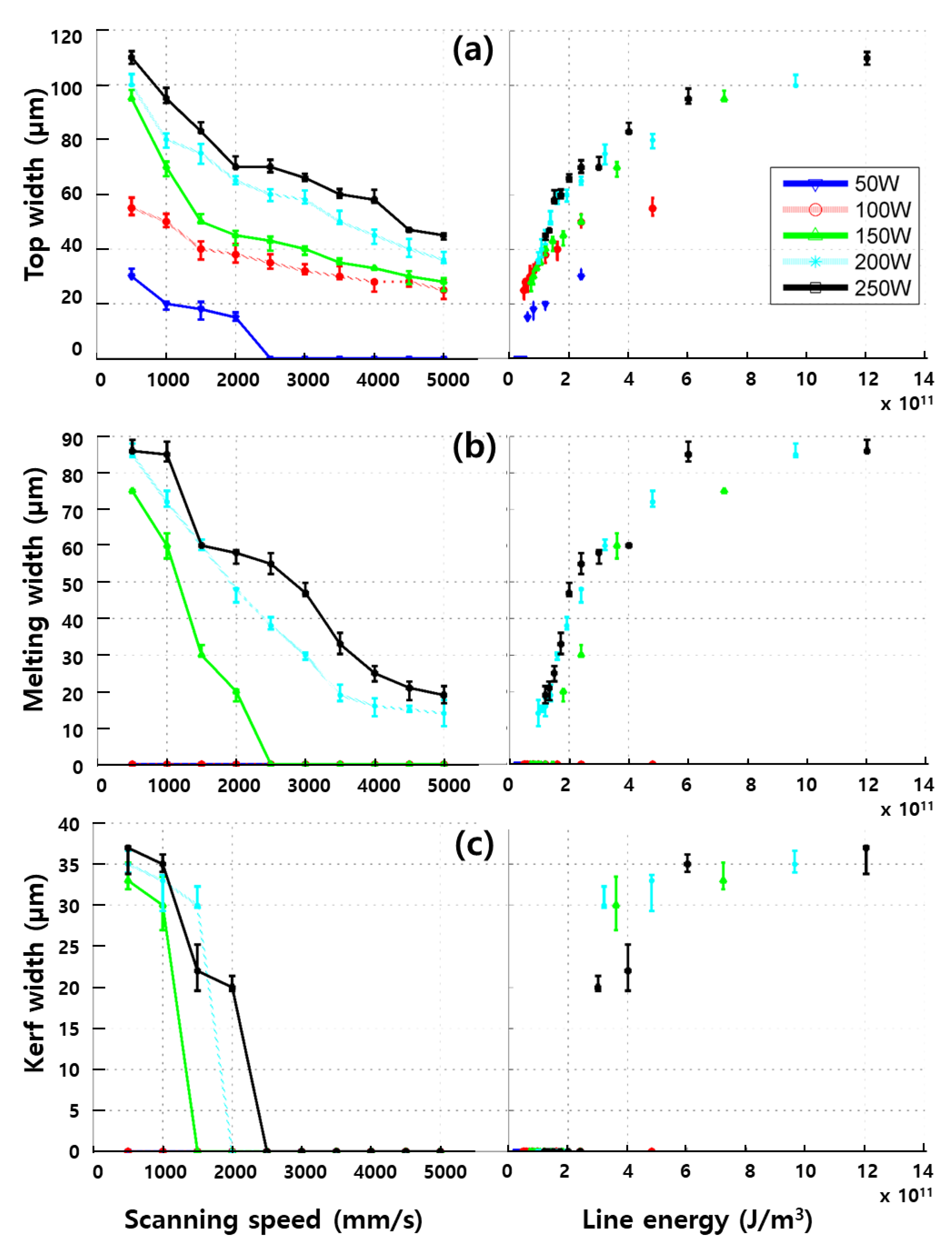
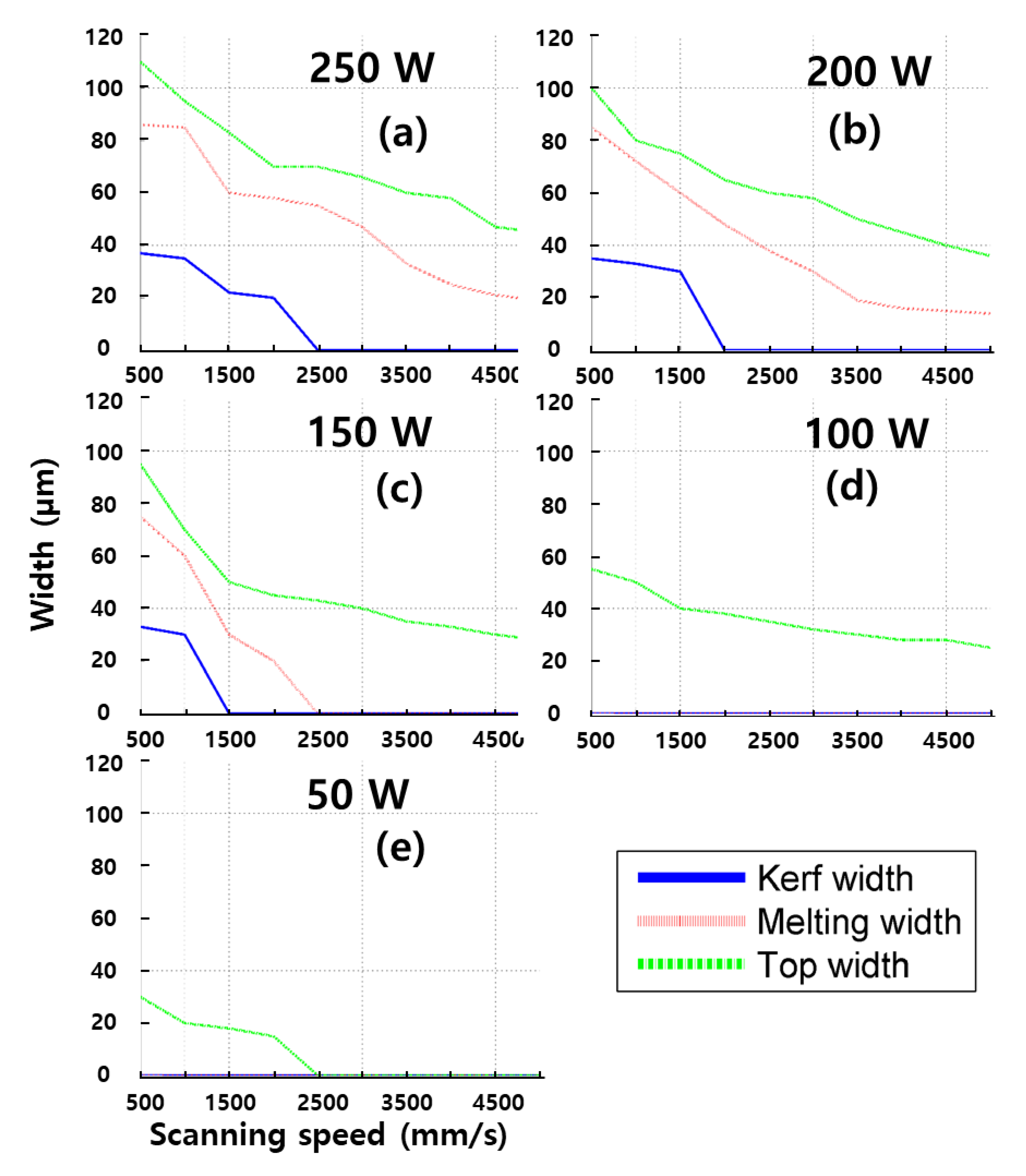
Figure 4 shows the top width, melting width, and kerf width. From the figures, the x-axis is depicted with two variables—laser scanning speed (Left) and line energy (Right). The definition of line energy can be referred to [2,11]. Figure 4a shows that increasing the scanning speed decreases the top width. With a laser power of 50 W, no top width is shown when the scanning speed is faster than 2000 mm/s. The top width is always observed when the laser power is greater than 50 W. In addition, increasing line energy increases top width. However, no active electrode material is removed when the line energy is less than 4.814 × 10¹⁰ J/m3. Therefore, it is 4.814 × 10¹⁰ J/m3 that is the line energy required to remove an active electrode material.
Figure 4b shows the melting width. Increasing scanning speed decreases the melting width. No melting width is formed when the laser power is less than 150 W. When the scanning speed is faster than 2000 mm/s, the melting width is not formed with a laser power of 150 W. A melting width is always observable when the laser power is greater than 150 W. According to the line energy, a line energy greater than 0.963 × 10¹⁰ J/m3 is required to form the melting width.
The comparison of the kerf width is shown in Figure 4c. Increasing the scanning speed decreases the kerf width. No kerf width is observed when the laser power is less than 150 W. To fully penetrate the anode, a scanning speed less than 1500 mm/s is required with a laser power of 150 W. Furthermore, scanning speeds less than 2000 mm/s and 2500 mm/s are required to fully penetrate the anode with laser powers of 200 W and 250 W, respectively. Full penetration can be achieved when the line energy is greater than 3.009 × 10¹⁰ J/m3.
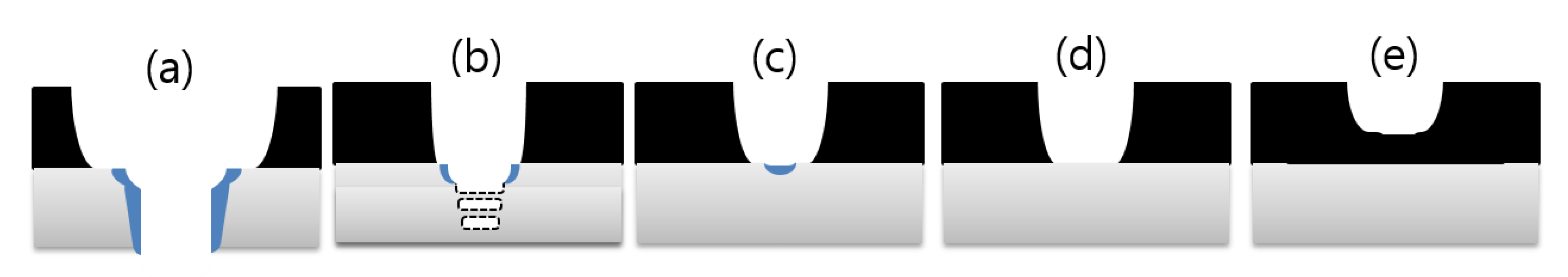
Figure 4 and Figure 5 show the variation of widths depending on laser power. SEM images are taken after the cutting is completed using the laser power of 250–50 W. Five types of classification with regard to physical phenomena are introduced and shown in Figure 6: (1) full penetration with wider top width of electrode; (2) partial penetration of current collector; (3) partial melting of current collector; (4) full ablation of active electrode material; and (5) partial ablation of active electrode material. It is interesting that full penetration with a narrower top width of the electrode is hardly observable.
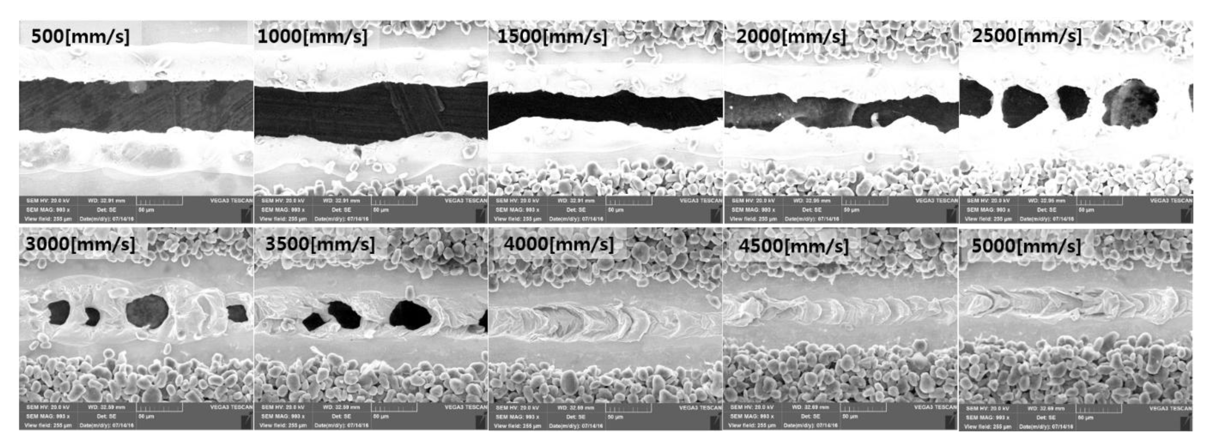
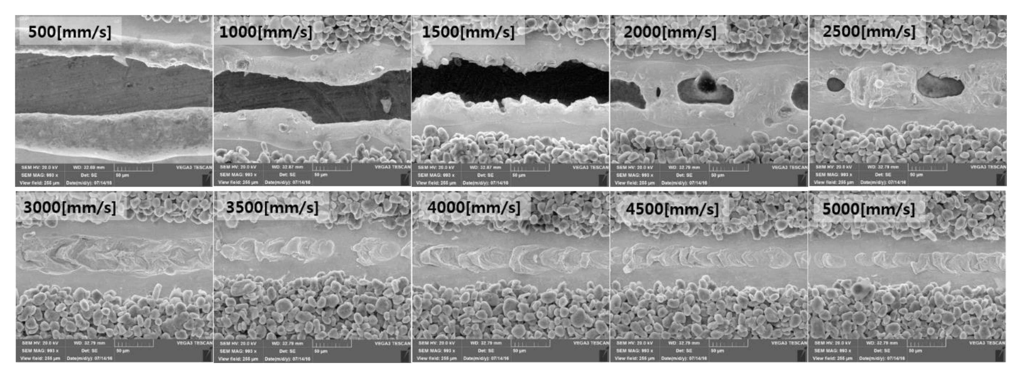
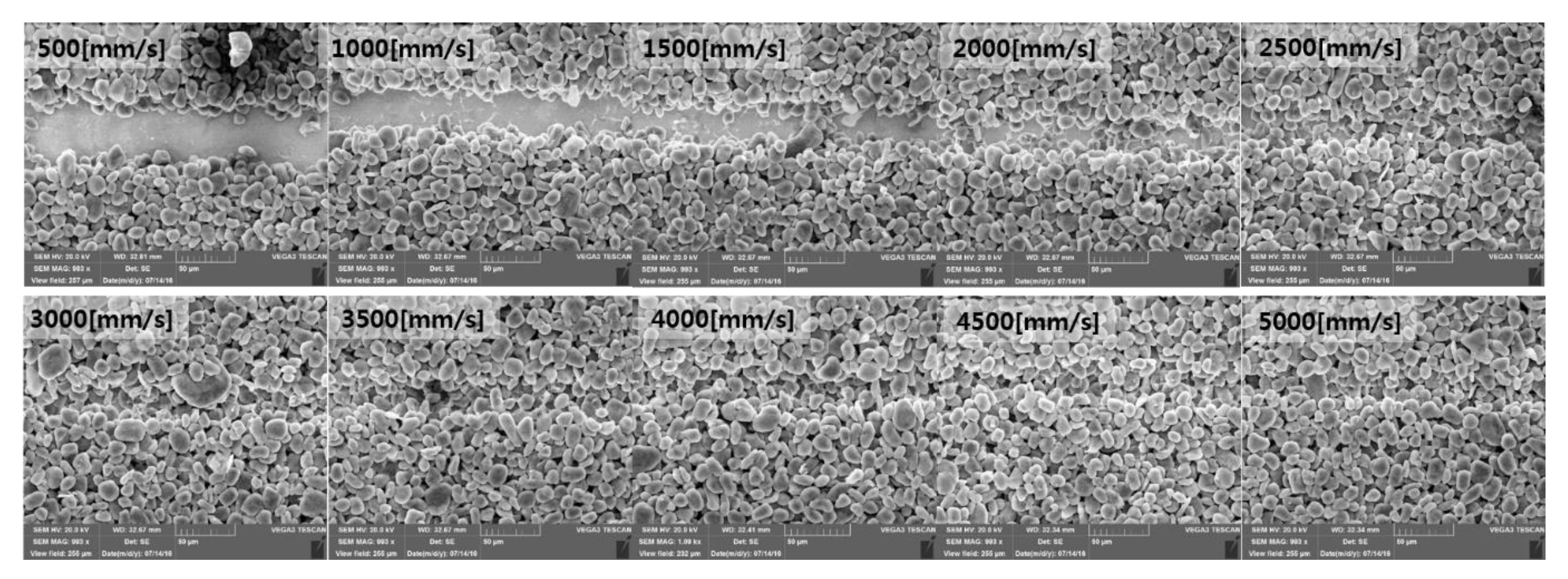
Figure 7 shows SEM images with a laser power of 250 W and these show very significant changes in terms of physical phenomena from the full penetration to the partial penetration to the partial melting. With a laser scanning speed of 500 mm/s to 2000 mm/s, full penetration with a wider top width of the electrode is observed. The melting widths are clearly observed and these are relatively wide compared to the widths observed for cathode materials. Moreover, the difference between the top width and melting width is narrower than the difference between the melting width and kerf width. With a laser scanning speed of 2500 mm/s to 3500 mm/s, partial penetration of the current collector is observed. This may have occurred due to sporadic evaporation as illustrated in Figure 8. Thus, partial penetration occurs at the point where the evaporation occurs. On the other hand, more frequent evaporation occurrence may lead to full penetration. The physical mechanism of partial penetration was explained by Lee et al. [27]. The forces caused by surface tension and recoil pressure are in a state of equilibrium and maintain a metastable state. When the force caused by surface tension increases, it leads to the formation of a connecting bridge as shown in Figure 8. On the other hand, increasing force caused by the recoil pressure results in full penetration. With a scanning speed of 4000 mm/s to 5000 mm/s, partial melting of the current collector is observed. The given laser parameters provide enough energy to remove the active electrode, but not enough energy to fully penetrate the current collector.
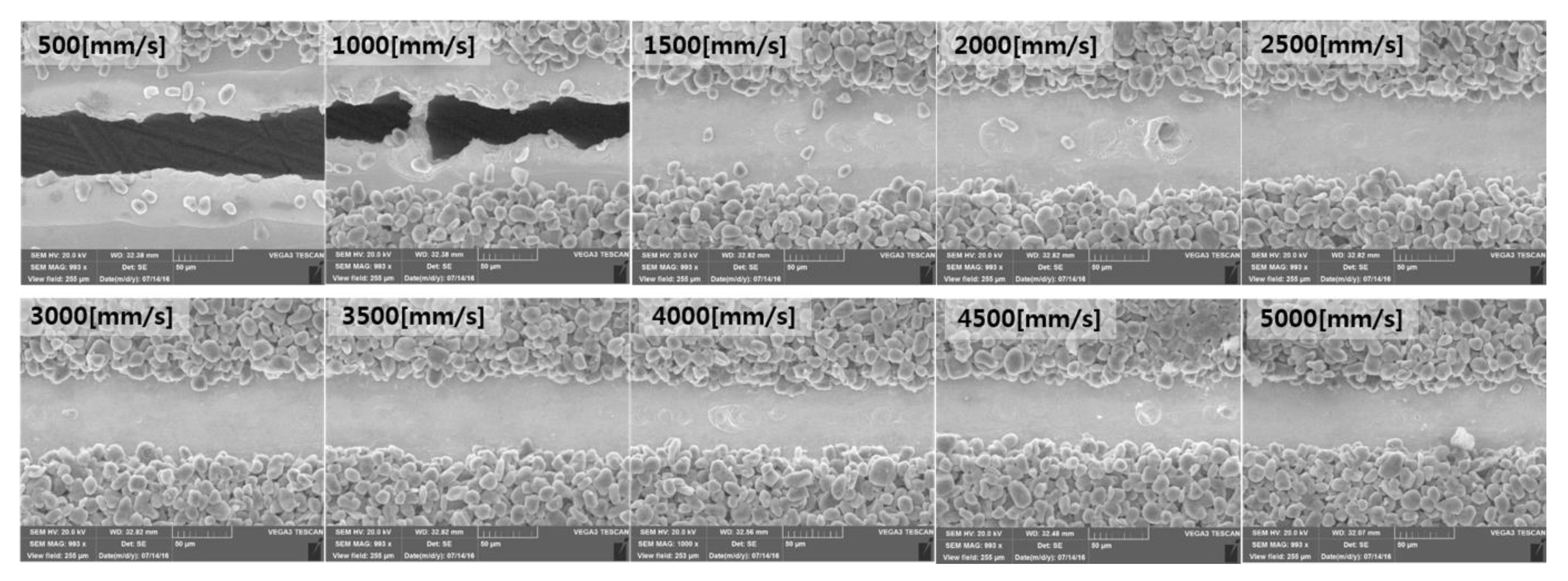
SEM images with a laser power of 200 W are shown in Figure 9. This also shows three types of physical phenomena such as full penetration of the electrode (laser scanning speed of 500 mm/s to 1500 mm/s), partial penetration of the current collector (laser scanning speed of 2000 mm/s to 2500 mm/s), and partial melting of the current collector (laser scanning speed of 3000 mm/s to 5000 mm/s). Under this laser power, a wider connecting bridge width is observed compared to the case of 250 W laser power. The full penetration and partial penetration of the current collector occur due to a combination of multiphysical phenomena such as heat conduction, heat convection, evaporation, melting, and re-solidification. On the contrary, the full and partial ablation of the active electrode material occurs with relatively simple physical phenomena such as heat conduction and the sublimation of graphite.
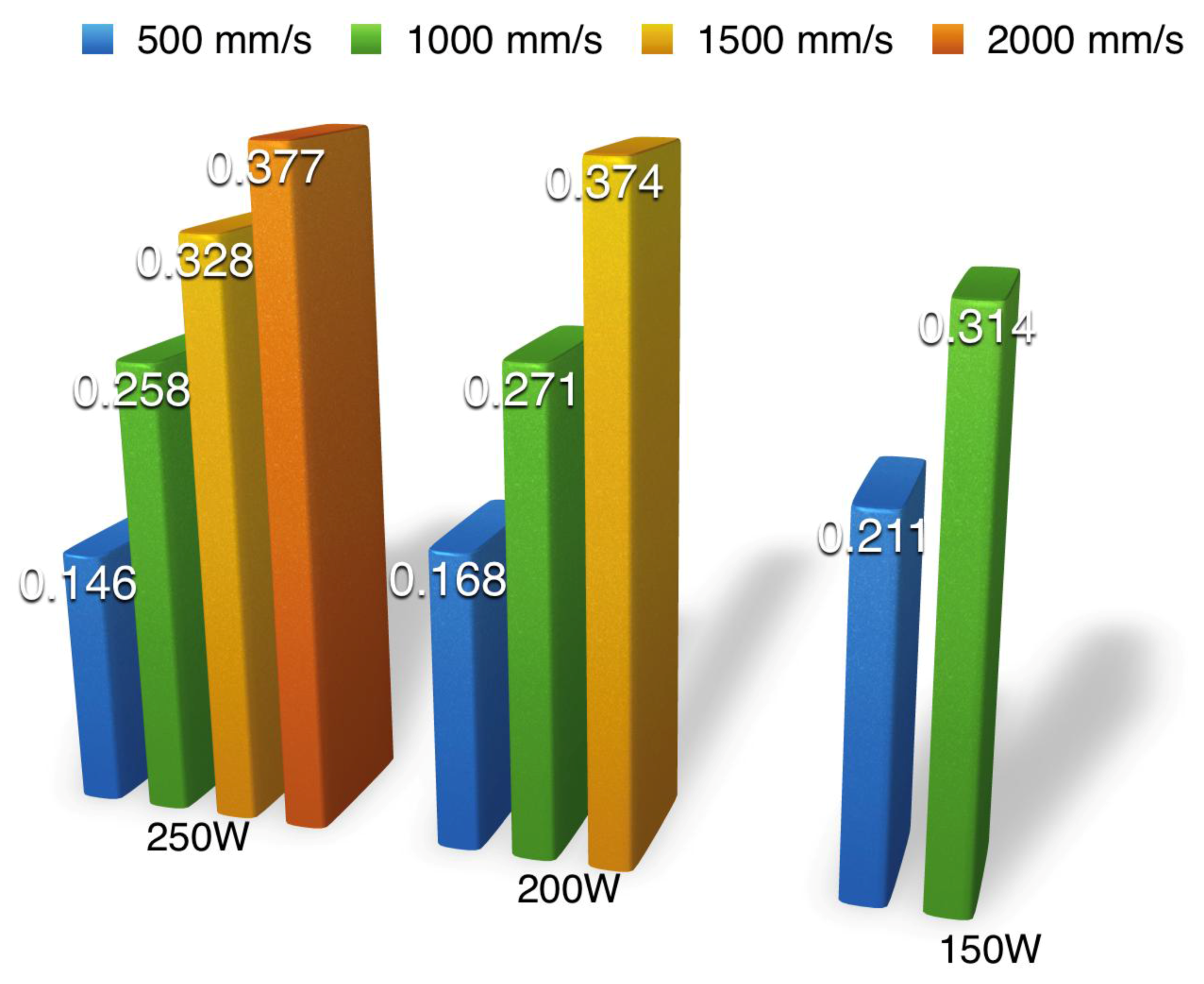
According to the analysis of the cutting efficiency discussed above, the cutting efficiency with appropriate material properties [15] for the case of full penetration is shown in Figure 10. The cutting efficiency varies from 14.6% to 37.7%. It is interesting that the cutting efficiency increases as the laser scanning speed increases. This is because losses due to thermal conduction make up a smaller portion of the absorbed energy [28]. Therefore, a higher laser cutting speed providing full penetration leads to higher cutting efficiency and productivity.
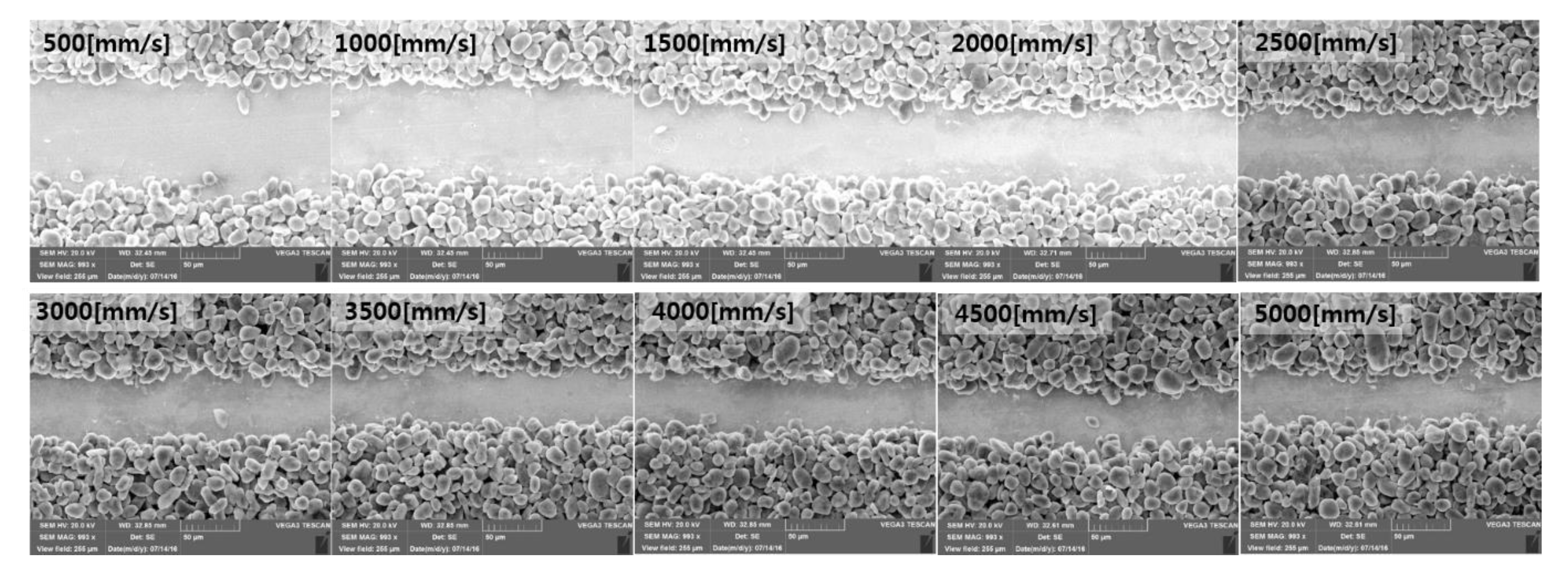
SEM images with a laser power of 150 W are shown in Figure 11. In this figure, full penetration of the electrode and full ablation of the active electrode material are observed. Moreover, SEM images with a laser power of 100 W, as shown in Figure 12, show only one type of physical phenomenon—the full ablation of the active electrode material. With the given laser power, full ablation of the active electrode material is introduced between 1500 mm/s and 5000 mm/s. In addition, full ablation of the active electrode material is the only geometrical classification observable with the given laser power of 100 W. Contrary to the partial melting observed in Figure 9, no geometrical change is observed on a current collector with a laser power of 150 W or 100 W. The full ablation is the dominant physical phenomenon observed in Figure 11 and Figure 12. Due to the wide processing window, these parameters causing the full ablation can be robustly used for the selective removal of the active electrode material with minimal damage to the current collector.
Figure 13 shows SEM images with a laser power of 50 W and two types of geometrical classification—the full and partial penetration of the active electrode material. With the given laser scanning speed of 500 mm/s and 2000 mm/s, full ablation of the active electrode material is seen. On the other hand, partial ablation of the active electrode material is observed when the laser scanning speed is between 2500 mm/s to 5000 mm/s. Under the given laser power, the top width is very similar to the laser spot size, or 23 μm, and the width of the partial ablation is less than the laser spot size. This can be possible since the Gaussian distribution of the laser beam is used.
5. Conclusions
To improve process stability and save additional cost, laser cutting was applied to cut electrodes for lithium-ion batteries. This study proposed specific widths such as melting width and top width for the analysis of laser cutting. The relationship between laser parameters, such as laser power, scanning speed, and line energy, and multiphysical phenomena with the proposed widths were investigated. Five types of geometrical classification with regard to physical phenomena were presented and explained with SEM images. Two or more types of physical phenomena were observed for each laser power level. Cutting efficiency was estimated with the proposed widths and its value varies from 14.6 to 37.7%. The cutting speed increases as the laser scanning speed increases. The specific cutting widths, five types of geometrical classification, and cutting efficiency proposed in this study will provide a standardized guideline for future research.
Acknowledgments
The research described herein was sponsored by the National Research Foundation of Korea (NRF) Grant funded by the Korean government (MSIP; Ministry of Science, ICT & Future Planning) (No. 2017R1C1B507916). The opinions expressed in this paper are those of the authors and do not necessarily reflect the views of the sponsors.
Conflicts of Interest
The author declares no conflict of interest.
Appendix A. Solution of Equations (7)–(9)
- (i)
- (ii)
References
- Scrosati, B.; Garche, J. Lithium batteries: Status, prospects and future. J. Power Sources 2010, 195, 2419–2430. [Google Scholar] [CrossRef]
- Lee, D.; Patwa, R.; Herfurth, H.; Mazumder, J. Parameter optimization for high speed remote laser cutting of electrodes for lithium-ion batteries. J. Laser Appl. 2016, 28, 368–380. [Google Scholar] [CrossRef]
- Wang, Q.; Ping, P.; Zhao, X.; Chu, G.; Sun, J.; Chen, C. Thermal runaway caused fire and explosion of lithium ion battery. J. Power Sources 2012, 208, 210–224. [Google Scholar] [CrossRef]
- Weng, F.; Chen, C.; Yu, H. Research status of laser cladding on titanium and its alloys: A review. Mater. Des. 2014, 58, 412–425. [Google Scholar] [CrossRef]
- Lee, D.; Cho, J.; Kim, C.H.; Lee, S.H. Application of Laser Spot Cutting on Spring Contact Probe for Semiconductor Package Inspection. Opt. Laser Technol. 2017, 97, 90–96. [Google Scholar] [CrossRef]
- Mazumder, J. Laser welding: State of the art review. JOM 1982, 34, 16–24. [Google Scholar] [CrossRef]
- Hong, K.-M.; Shin, Y.C. Prospects of laser welding technology in the automotive industry: A review. J. Mater. Process. Technol. 2017, 245, 46–69. [Google Scholar] [CrossRef]
- Steen, W.M.; Mazumder, J. Laser Material Processing, 4th ed.; Springer: London, UK, 2010. [Google Scholar]
- Lee, D. Experimental Investigation of Laser Spot Welding of Ni and Au-Sn-Ni Alloy. J. Weld. Join. 2017, 35, 1–5. [Google Scholar] [CrossRef]
- Pfleging, W. A review of laser electrode processing for development and manufacturing of lithium-ion batteries. Nanophotonics 2017. [Google Scholar] [CrossRef]
- Lee, D.; Patwa, R.; Herfurth, H.; Mazumder, J. Three dimensional simulation of high speed remote laser cutting of cathode for lithium-ion batteries. J. Laser Appl. 2016, 28. [Google Scholar] [CrossRef]
- Lee, D. Modeling of High Speed Remote Laser Cutting for Lithium-Ion Batteries; Scholar’s Press: Kolkata, India, 2016. [Google Scholar]
- Lee, D.; Patwa, R.; Herfurth, H.; Mazumder, J. High speed remote laser cutting of electrodes for lithium-ion batteries: Anode. J. Power Sources 2013, 240, 368–380. [Google Scholar] [CrossRef]
- Lee, D.; Mazumder, J. Numerical Studies of Laser Cutting of an Anode for Lithium-ion Batteries. In Proceedings of the 31st International Congress on Applications of Lasers & Electro-Optics, Anaheim, CA, USA, 23–27 September 2012. [Google Scholar]
- Lee, D. Modeling of high speed remote laser cutting of electrodes for lithium-ion batteries University of Michigan. J. Power Sources 2012, 240, 368–380. [Google Scholar] [CrossRef]
- Patwa, R.; Herfurth, H.; Heinemann, S.; Mazumder, J.; Lee, D. Investigation of different laser cutting strategies for sizing of Li-Ion battery electrodes. In Proceedings of the 31st International Congress on Applications of Lasers & Electro-Optics, Anaheim, CA, USA, 23–27 September 2012. [Google Scholar]
- Mazumder, J.; Lee, D.; Tübke, J.; Pinkwart, K.; Herfurth, H.; Patwa, R. High Speed Laser Cutting of Electrodes for Lithium Ion Batteries; University of Michigan Fraunhofer: East Lansing, MI, USA, 2011. [Google Scholar]
- Lee, D.; Mazumder, J. Numerical Studies of Laser Cutting on an Active Electrode Material for Lithium-ion Batteries. In Proceedings of the 30th International Congress on Applications of Lasers & Electro-Optics, Orlando, FL, USA, 23–27 October 2011. [Google Scholar]
- Lee, D.; Mazumder, J. The Numerical Studies of the Laser Processing Parameters on Copper and Aluminum during Laser Cutting. Proceeding of the 29th International Congress on Applications of Lasers & Electro-Optics, San Jose, CA, USA, 16–21 May 2010. [Google Scholar]
- Patwa, R.; Herfurth, H.J.; Pantsar, H.; Heinemann, S.; Mazumder, J.; Lee, D. High speed laser cutting of electrodes for advanced batteries. In Proceedings of the 29th International Congress on Applications of Lasers & Electro-Optics, San Jose, CA, USA, 16–21 May 2010. [Google Scholar]
- Lutey, A.H.; Fortunato, A.; Carmignato, S.; Ascari, A.; Liverani, E.; Guerrini, G. Quality and Productivity Considerations for Laser Cutting of LiFePO4 and LiNiMnCoO2 Battery Electrodes. Procedia CIRP 2016, 42, 433–438. [Google Scholar] [CrossRef]
- Lutey, A.H.A.; Fortunato, A.; Ascari, A.; Carmignato, S.; Leone, C. Laser cutting of lithium iron phosphate battery electrodes: Characterization of process efficiency and quality. Opt. Laser Technol. 2015, 65, 164–174. [Google Scholar] [CrossRef]
- Luetke, M.; Franke, V.; Techel, A.; Himmer, T.; Klotzbach, U.; Wetzig, A.; Beyer, E. A Comparative Study on Cutting Electrodes for Batteries with Lasers. Phys. Procedia 2011, 12, 286–291. [Google Scholar] [CrossRef]
- Demir, A.G.; Previtali, B. Remote cutting of Li-ion battery electrodes with infrared and green ns-pulsed fibre lasers. Int. J. Adv. Manuf. Technol. 2014, 75, 1557–1568. [Google Scholar] [CrossRef] [Green Version]
- Lee, D.; Ahn, S. Investigation of Laser Cutting Width of LiCoO2 Coated Aluminum for Lithium-Ion Batteries. Appl. Sci. 2017, 7, 914. [Google Scholar] [CrossRef]
- Kannatey-Asibu, E. Principles of Laser Materials Processing; Wiley: Hoboken, NJ, USA, 2009. [Google Scholar]
- Lee, D.; Mazumder, J. Effects of laser beam spatial distribution on laser-material interaction. J. Laser Appl. 2016, 28. [Google Scholar] [CrossRef]
- Schulz, W.; Becker, D.; Franke, J.; Kemmerling, R.; Herziger, G. Heat conduction losses in laser cutting of metals. J. Phys. D Appl. Phys. 1993, 26, 1357. [Google Scholar] [CrossRef]
Figure 1.
Definition of top, melting, and kerf width.

Figure 2.
Definition of areas for cutting efficiency.

Figure 3.
Description of laser power irradiation with a laser power of 250 W, speed of 5000 mm/s, and distance of 100 .
Figure 3.
Description of laser power irradiation with a laser power of 250 W, speed of 5000 mm/s, and distance of 100 .

Figure 4.
Comparison of (a) Top width; (b) Melting width; (c) Kerf width.

Figure 5.
Variation of widths depending on laser power: (a) 250 W, (b) 200 W, (c) 150 W, (d) 100 W, (e) 50 W.
Figure 5.
Variation of widths depending on laser power: (a) 250 W, (b) 200 W, (c) 150 W, (d) 100 W, (e) 50 W.

Figure 6.
Category of five physical phenomena: (a) full penetration with a wider top width of the electrode; (b) the partial penetration of current collector; (c) the partial melting of the current collector; (d) full ablation of active electrode material; (e) partial ablation of active electrode material.

Figure 7.
SEM images with a laser power of 250 W.

Figure 8.
Evaporation points for (a) partial penetration and (b) full penetration.

Figure 9.
SEM images with a laser power of 200 W.

Figure 10.
Cutting efficiency for full penetration.

Figure 11.
SEM images with a laser power of 150 W.

Figure 12.
SEM images with a laser power of 100 W.

Figure 13.
SEM images with a laser power of 50 W.


Table 1.
Laser parameters.
| # | Power (W) | Speed (mm/s) | Line Energy (J/m3) |
|---|---|---|---|
| 50, 100, 150, 200, 250 | 500, 1000, 1500, 2000, 2500, 3000, 3500, 4000, 4500, 5000 | 4.348 × 10⁵~2.174 × 10⁷ |
© 2018 by the author. Licensee MDPI, Basel, Switzerland. This article is an open access article distributed under the terms and conditions of the Creative Commons Attribution (CC BY) license (http://creativecommons.org/licenses/by/4.0/).
Share and Cite
MDPI and ACS Style
Lee, D. Investigation of Physical Phenomena and Cutting Efficiency for Laser Cutting on Anode for Li-Ion Batteries. Appl. Sci. 2018, 8, 266. https://0-doi-org.brum.beds.ac.uk/10.3390/app8020266
AMA Style
Lee D. Investigation of Physical Phenomena and Cutting Efficiency for Laser Cutting on Anode for Li-Ion Batteries. Applied Sciences. 2018; 8(2):266. https://0-doi-org.brum.beds.ac.uk/10.3390/app8020266
Chicago/Turabian StyleLee, Dongkyoung. 2018. "Investigation of Physical Phenomena and Cutting Efficiency for Laser Cutting on Anode for Li-Ion Batteries" Applied Sciences 8, no. 2: 266. https://0-doi-org.brum.beds.ac.uk/10.3390/app8020266
Note that from the first issue of 2016, this journal uses article numbers instead of page numbers. See further details here.