Noise-Canceling Office Chair with Multiple Reference Microphones


Department of Measurement and Information Systems, Budapest University of Technology and Economics, 1111 Budapest, Hungary
*
Author to whom correspondence should be addressed.
†
These authors contributed equally to this work.
Appl. Sci. 2018, 8(9), 1702; https://0-doi-org.brum.beds.ac.uk/10.3390/app8091702
Submission received: 31 August 2018
/
Revised: 14 September 2018
/
Accepted: 16 September 2018
/
Published: 19 September 2018
(This article belongs to the Special Issue Active and Passive Noise Control)
Abstract
:Office employees are exposed to acoustic noise, especially in an open office environment. Passive or active headsets sufficiently reduce the level of noise, but their long-time wear is uncomfortable. The paper presents an active headrest system built into a chair. Feedforward control is utilized with multiple reference microphones, and flexible gooseneck microphones serve as error sensors. The reference sensors surround the chair, allowing the suppression of sound waves arriving from any direction. The concept of multiple reference control has been tested by extensive experiments showing that multiple reference signals help to increase the suppression in normal rooms where reverberation occurs, even if only one noise source is present. The preliminary experiments are completed by a series of simulations aiming to explore the zones of quiet at the user’s ears. The paper introduces the construction details of the noise-canceling chair: The two loudspeakers are controlled by the signals of two error microphones and four reference signals. The controller is based on the normalized filtered error least mean squared algorithm, implemented on an Analog Devices ADSP-21262 signal processor-based hardware. Experimental results are reported that show the efficient suppression of tonal, as well as broadband disturbances.
1. Introduction
Active noise control has been present in research and development, as well as in practical applications in the last three decades [1,2]. Personal noise control is one of the most successful implementations of the general principle, due to the small enclosure where noise reduction is to be achieved. Noise control in vehicles, airplanes and headphones are typical examples. Noise-canceling headphones have already become commercial products, and they are available at different prices and are popular among users [3].
Nowadays, offices are often noisy, especially so-called open offices. The main distractions are ringing phones, loud office machines, conversations, etc. Wearing a headphone equipped with active noise control is a straightforward solution to the problem. However, their long-time wear, up to a full eight-hour workday, is uncomfortable. An alternative solution to the noise control problem is an active headrest system built into a chair. Assuming that an office employee mostly sits in the chair, this is a suitable solution. To accommodate human ears, two secondary sources have to be located in the headrest. The installation details of the reference and error microphones and the specific control algorithm can be selected in different ways based on the objectives.
Several similar noise-canceling systems are presented in the literature, e.g., [4,5,6,7,8]. They all discussed an active headrest system, and some of them introduced a noise-canceling chair specifically [6,7]. The papers cited here show that there are some open algorithmic and technological questions. The papers report on experimental results, made in an anechoic or semi-anechoic chamber [7,8] or in a laboratory [4,5,6]. In reflective rooms, the acoustic fields to be controlled are more complex, which limits the performance in a sense. A typical simplification is that the systems usually control periodic or complex tonal disturbances [5,6,7,8]. The paper [4] includes experiments with broadband noise, as well.
The systems described in [4,5,6,7] utilized feedback control, and only [8] applied a feedforward control. The reason for that is two-fold. Firstly, feedback control requires simpler equipment. Secondly, in this noise control problem, the location of the primary sources is unknown in advance, so the reference microphones cannot be installed properly. However, feedback control is inappropriate or only slightly appropriate for broadband control. Narrowband and colored noise has been suppressed only by 4–7 dB by feedback control [4].
The main development has been focused on the acquisition of the error signals. Active control minimizes the acoustic pressure at the error microphones, resulting in a zone of quiet. Considering a diffuse sound field and a 10-dB reduction of the primary sound pressure level, this zone is a sphere-like volume with a diameter of about one tenth of the excitation wavelength [9]. Assuming noise control up to 1 kHz, the diameter of the zone is about 3.4 cm. This implies that error microphones built into the headrest cannot be sufficiently utilized. To overcome this problem, virtual sensing algorithms have been developed [10]. The aim of virtual sensing is to estimate both the primary and the secondary sound field at specified locations, away from the physically-installed microphones. The specified locations are the virtual locations, where the virtual or remote microphones are located. In the case of active headrest systems, physical microphones are usually built into the headrest, and virtual microphones are placed at the ears. As the ears’ position can vary during the operation, head-tracking can also be applied.
The paper [10] gives a comprehensive review of different algorithms; here, only the virtual microphone technique (VMT) and the remote microphone technique (RMT) are recalled. Both the VMT and the RMT estimate the secondary sound field by filtering the signals of the secondary sources. They require the identification of the transfer functions between the secondary sources and the virtual microphones in advance. In the identification phase, physical microphones are placed at the virtual positions. The VMT assumes that the primary sound pressure of the virtual microphone equals that of the physical microphone. While the magnitudes at the two locations can be largely equal, the phase can differ significantly at the same time. Hence, the estimation of the primary field by the VMT can be inaccurate. The RMT is the improved version of the VMT, as it estimates the primary field more precisely. This is accomplished by filtering the physical error signals by the transfer functions between the physical and the virtual microphones, with respect to the positon of the primary source. It also requires the identification of the appropriate transfer functions in advance. However, if the position of the primary source changes, the estimation is no longer correct. These algorithms estimate the error signal at the virtual locations, at the expense of modeling additional transfer functions. In the case of active headrest systems, where at least two microphones and two loudspeakers are installed, the VMT requires one and the RMT two filter matrices.
The authors of the cited works have used different algorithms. In the noise-canceling chair reported in [6], no virtual sensing is applied, and the emphasis is on the low computational demand. The system could suppress complex tonal disturbance (motorcycle noise) in the low frequency range. The VMT has been successfully used by [4]. Up to a 20-dB reduction has been achieved for tonal noise and only 4–7 dB for narrowband random noise. The superiority of the RMT has been proven in [5], but only a single frequency tonal noise has been used for the experiments. Recently, a noise-canceling office chair equipped with a very complex controller has been published [7]. The RMT has been applied, complemented by an ultrasonic head-tracking system. The actual transfer functions are chosen by the estimated head position. The performance of the chair has been tested in simulations, where tonal noise has been applied at different frequencies. A similar system is described in [8] with more emphasis on the theoretical investigations.
Offices are moderately damped rooms where many reflections occur, and not only tonal, but broadband noises are present, as well. In addition, the positions and even the number of the primary sources vary. In a sense, these impose contradictory requirements on the noise controller to be designed. Broadband noise calls for feedforward control, but the arrangement of the reference microphones has to be carefully considered. The error microphones should be located near the ears, so as not to cause any discomfort. To fulfill the latter requirement, the remote microphone technique is a feasible solution. However, it has a high computational demand, and the varying position of the primary sources deteriorates its efficiency.
Our noise-canceling chair controls not only tonal, but also broadband disturbances, generated at any point of the room. To achieve this, feedforward control is applied. To overcome the problem of varying primary sources, multiple reference microphones are utilized that surround the chair. Our preliminary investigations have shown that in such rooms, multiple reference signals result in greater suppression, even if only one primary noise source is present. Instead of the widespread filtered-reference least mean squared (XLMS) algorithm, the filtered-error least mean squared (ELMS) algorithm [11] has been applied. The ELMS algorithm ensures faster convergence and needs less computations in this special case, when multiple reference signals are processed. Mainly because of the high computational demand, the remote microphone technique is rejected. We have used two flexible gooseneck microphones fastened to the headrest. The user can adjust the microphone positions to a comfortable distance from the ears.
The paper is organized as follows. Section 2 introduces some preliminary investigations that establish the design of the noise-canceling chair. The construction details are described in Section 3, while Section 4 deals with the experimental results. Conclusions and future work are summarized in Section 5.
2. Preliminary Investigations
2.1. Conceptual Considerations
A fundamental requirement for our noise control system was the ability to suppress broadband noise. Although tonal noise is more disturbing than a broadband noise of equal power, the cancellation of only the tonal components in an office results in minor overall suppression. Broadband noise usually has significant power around the 1-kHz frequency where passive shielding is still not appropriate, so we have aimed to control the noise field up to 1 kHz.
If random noise is to be suppressed, feedforward control is the most suitable solution [1]. Feedforward control needs reference signals correlated with the primary noise. If there are multiple noise sources, each source should be monitored by its own reference microphone. This principle can be maintained if a dedicated noise control is designed specifically for a given location. However, in our case, neither the position of the chair, nor the position of the primary sources, nor the room were known in advance. Nevertheless, high correlation between the error signal and the primary noise can also be ensured if the reference microphone is close to the error microphone. To retain the causality of the control filter, the direct sound from the primary source shall reach the reference microphone earlier than the error microphone. This requirement is not necessary for tonal disturbance control, but essential in the case of random noise. As the primary sources can appear in various positions in the room, more than one reference microphone is to be used, in order to cover the possible directions. Generalizing the idea, several reference microphones should surround the chair, allowing the suppression of the primary noise generated at any position in the room. Furthermore, this arrangement is capable of controlling multiple primary sources. This concept has been tested intensively by experiments, which are introduced below.
Concerning the chair itself, the two loudspeakers have to be built into the headrest, similarly to other solutions; see, e.g., [6]. The main problem is the acquisition of the error signals. As previously mentioned, physical microphone-based sensing has been chosen. This solution allows one to spend most of the computational capacity on the calculation of the adaptive control filters. As the users’ ears are in different positions relative to the headrest, the positions of the error microphones have to be set individually. To this end, flexible gooseneck microphones are installed. Now, the size of the zones of quiet is left to be determined. As was cited in the Introduction, for diffuse sound fields, about a 10-dB reduction can be achieved inside a sphere of a diameter of one tenth of the wavelength. This diameter is 3.4 cm at 1 kHz, which can be accommodated by physically adjusting the microphone positions, without discomfort to the user. The zones of quiet have to be estimated for the direct sound field, as well; hence, simple simulations have been carried out, the results of which are also reported in this section.
2.2. Experiments
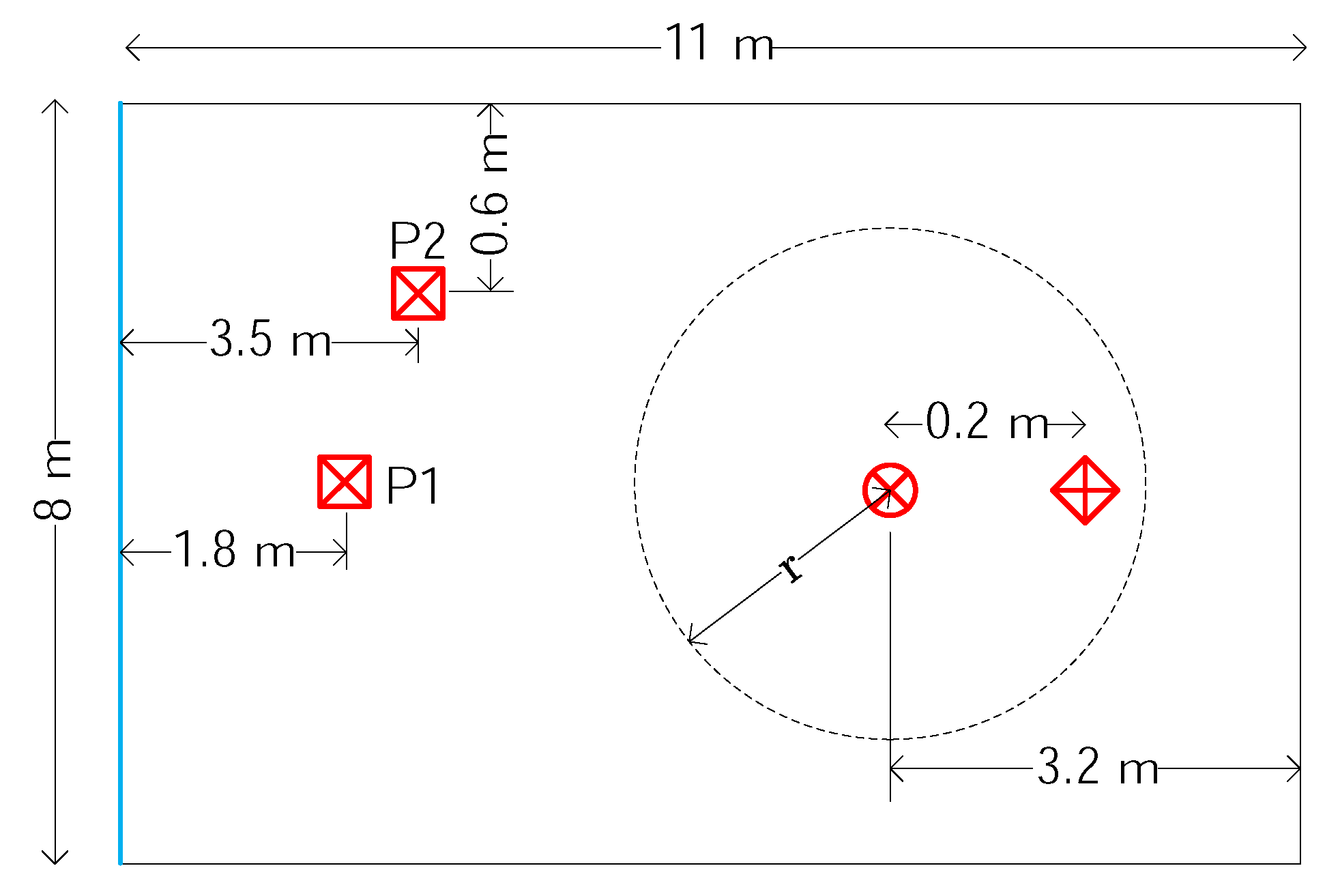
The measurements took place in an 8 by 11 by 2.8 m classroom with only a handful of chairs and tables in it, which produced a reverberant environment like ordinary offices. The room was located in a multi-story building and had a concrete floor and ceiling and plasterboard walls. On one end, it had a wall-to-wall glass window, on the other a large door and metal whiteboard. Along one side, it had large metal containers. The floor plan with the measurement arrangement can be seen in Figure 1. Special symbols have been used to denote the objects that are explained in Figure 2.
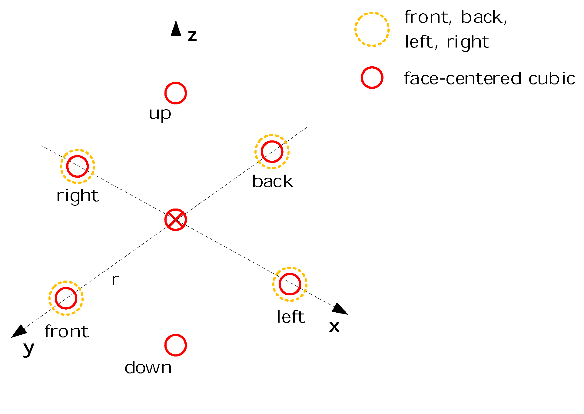
Only one secondary source and one error microphone have been used, instead of two pairs. No different result was expected in the latter case, but it would have required much more computation. The primary sources were emitted band limited white noise of 500 Hz. The figure is only hinting at the locations of the reference microphones, which are installed around the error microphone with radius r. A detailed closeup of their arrangement can be seen in Figure 3.
Other arrangements have also been tested that are not depicted in the figure: a regular triangle in the x-y plane for 3 microphones, a regular tetrahedron for 4 microphones and a regular hexagon in the x-y plane for 6 microphones. The error microphone is set in all cases in the reference microphones’ center of gravity. The influence of the radius has also been tested.
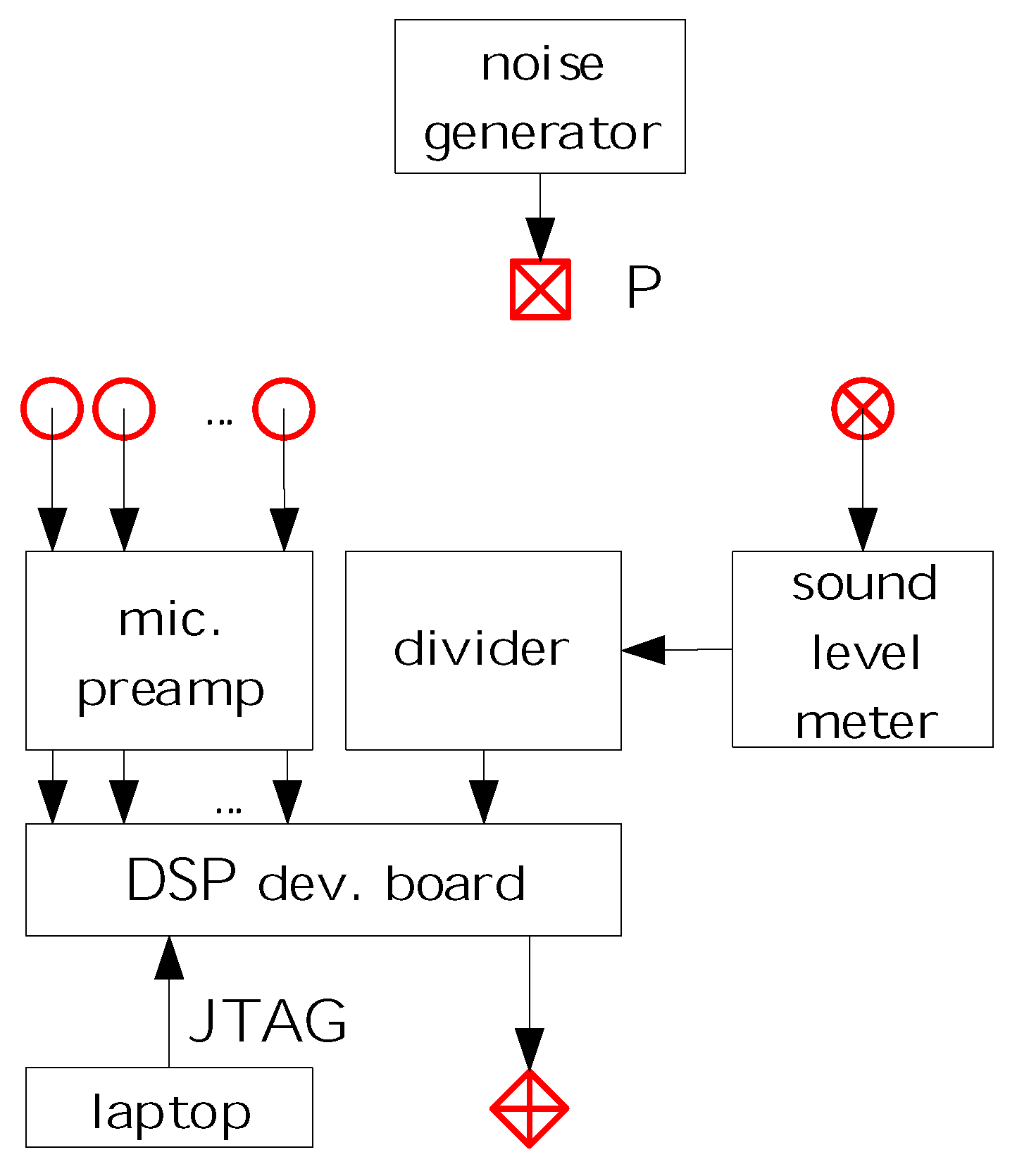
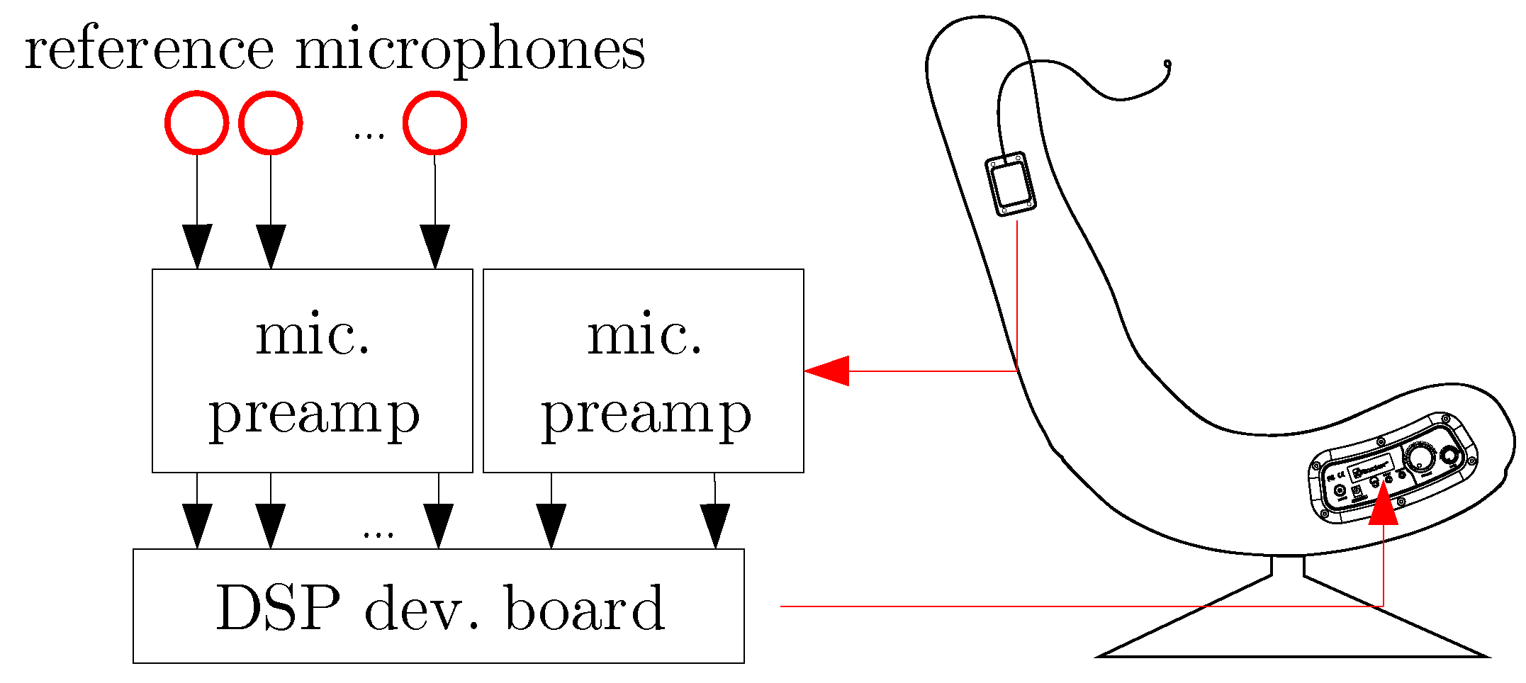
The main parts of the control equipment can be seen in Figure 4. Behringer ECM8000-type ultra-linear condenser microphones have been used for reference signal acquisition, while a Voltcraft SL-400-type sound level meter has been used for the measurement of the error signal. The probe has been connected to the meter by an extension cable; thus, the error microphone could easily be set to the right position. The primary noise has been emitted by Genius SP-HF 1250B-type loudspeakers, and an Altec ACS52 type speaker has been used as the secondary source. As the bandwidth of the primary noise is 500 Hz, the sources could be considered omnidirectional. An Analog Devices AD21262 signal processor-based hardware has been used for control, which will be presented in detail in the next section. A normalized filtered reference LMS algorithm has been implemented on the controller. Each reference microphone had its own control filter, and the sum of the outputs drove the secondary loudspeaker. The filters had an equal number of taps, and the total number of taps reached the maximum allowed by the hardware, i.e., the more reference signals have been used, the shorter the control filter that has been implemented. Thus, the tap number of the control filters was a variable. The sampling frequency was 8 kHz.
The parameters and their settings are summarized in Table 1. This variety of the parameters resulted in numerous measurements. Below, some interesting results and the conclusion are described.
The most interesting results have been derived from a series of measurements when the number of the reference microphones has been changed from 1 to 6 and the primary source has been set to positions P1 and P2. The common radius for the reference microphones has been set to 1 m. The results are summarized in Table 2. Figure 1 and Figure 3 help to identify the positions of the primary source and the reference microphones.
Nearly equal suppression could be achieved for positions P1 and P2. Generally, longer adaptive filters produced greater suppression, as expected. However, if only one reference microphone has been used, only about a 3-dBA suppression could be achieved, and increasing the adaptive filter length from 4000 to 8000 did not result in greater suppression. The deployment of 2, 3, 4 and 6 reference signals resulted in increasingly better suppression, while the sum of the filter taps was set to about 8000, which is the maximum that could be implemented on the signal processor. Other experiments with different radii of the reference microphones had shown similar results. Slightly worse results were obtained if m was set, mainly because of the loss of causality as the hardware has an inevitable delay. On the other hand, reference microphones at a distance of m are too far from the error microphone, which is less favorable for the hardware design.
The experiments have shown that multiple reference signals helped to increase the suppression, even if only one primary source was present. This is an advantageous feature, which can be exploited during the noise-canceling chair design.
2.3. Simulations
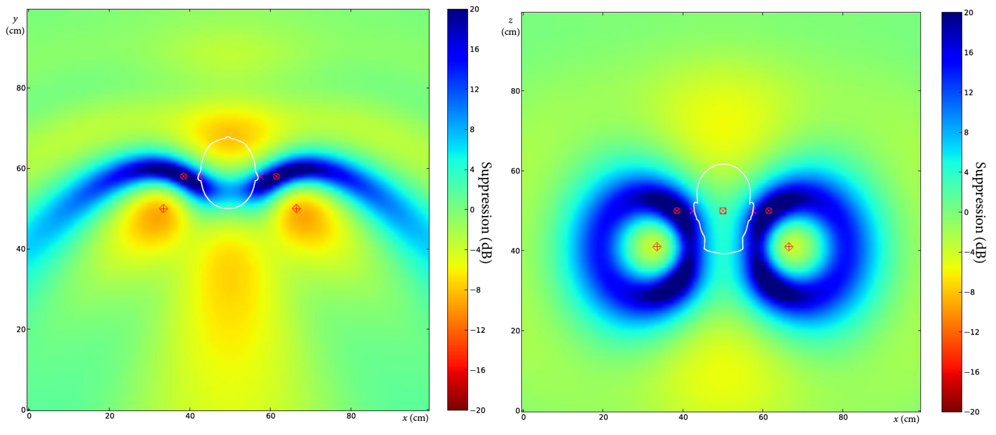
The goal of the simulations was to estimate the zones of quiet around the error microphones assuming a direct sound field. Considering broadband control, the zone of quiet can be estimated by applying tonal noise of different frequencies, covering the entire bandwidth. As the zone shrinks when increasing the frequency of the sound, the most careful simulations had to be carried out near the cut-off frequency of the designed bandwidth, i.e., at a frequency of 1 kHz. The calculations have been carried out with two important simplifications. First, the sound field has been calculated assuming far field, i.e., the sound pressure level is inversely proportional to the distance from the source. This assumption is not correct for the secondary sources at low frequencies, but fair near 1 kHz. On the other hand, it is expected that the zones of quiet are large enough at low frequencies, and their extent is crucial only at higher frequencies. Hence, the simulations are informative in the most important cases. The second simplification is that the influence of the user’s head is ignored. This choice is based on the fact that the head starts to shadow the ear farther away from the sound only at frequencies above 1500 Hz [12]. Thus, simple simulations for active noise control can neglect the effect of the head. As there are two secondary sources and two error microphones, the sound field generated by the secondary loudspeakers perfectly cancels the primary noise at the error microphones.
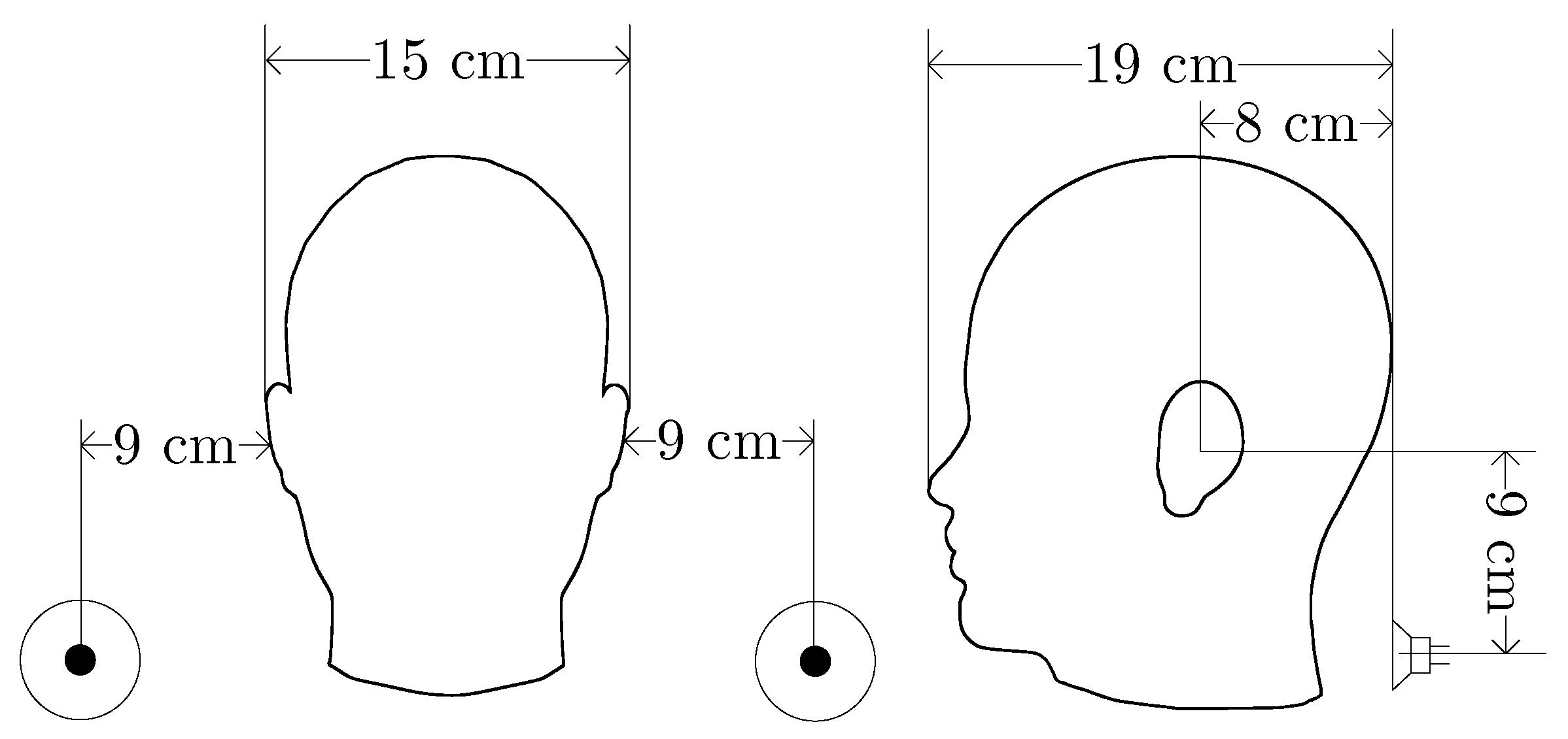
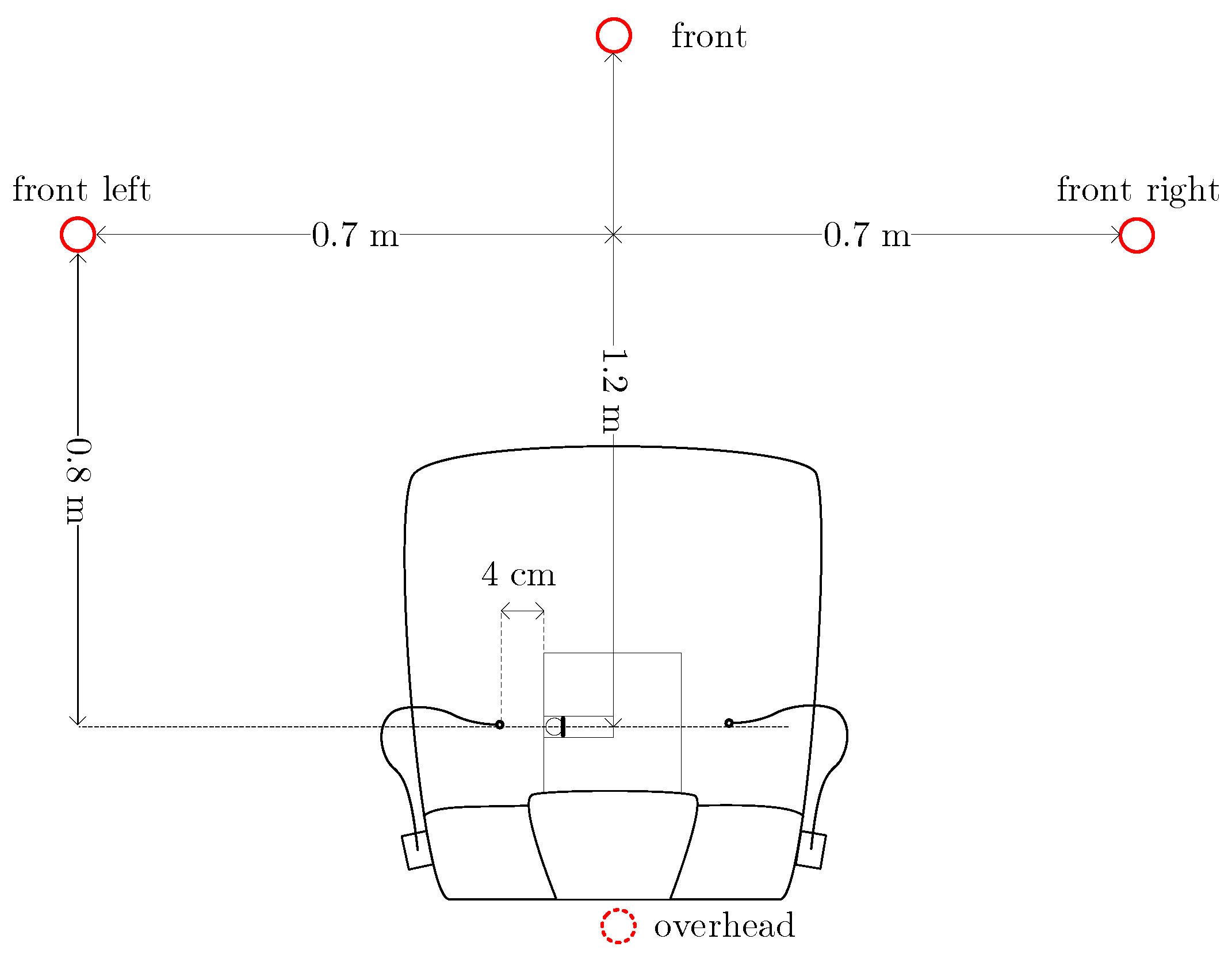
Our noise-canceling chair is based on the X Rocker Gaming Chair [13]. The relative positions of the secondary sources and the user’s ears, as well as the error microphones have been set according to the size of the chair. The dimensions of the head and the positions of the loudspeakers can be seen in Figure 5. The loudspeakers on the left are indicated by two co-axial circles.
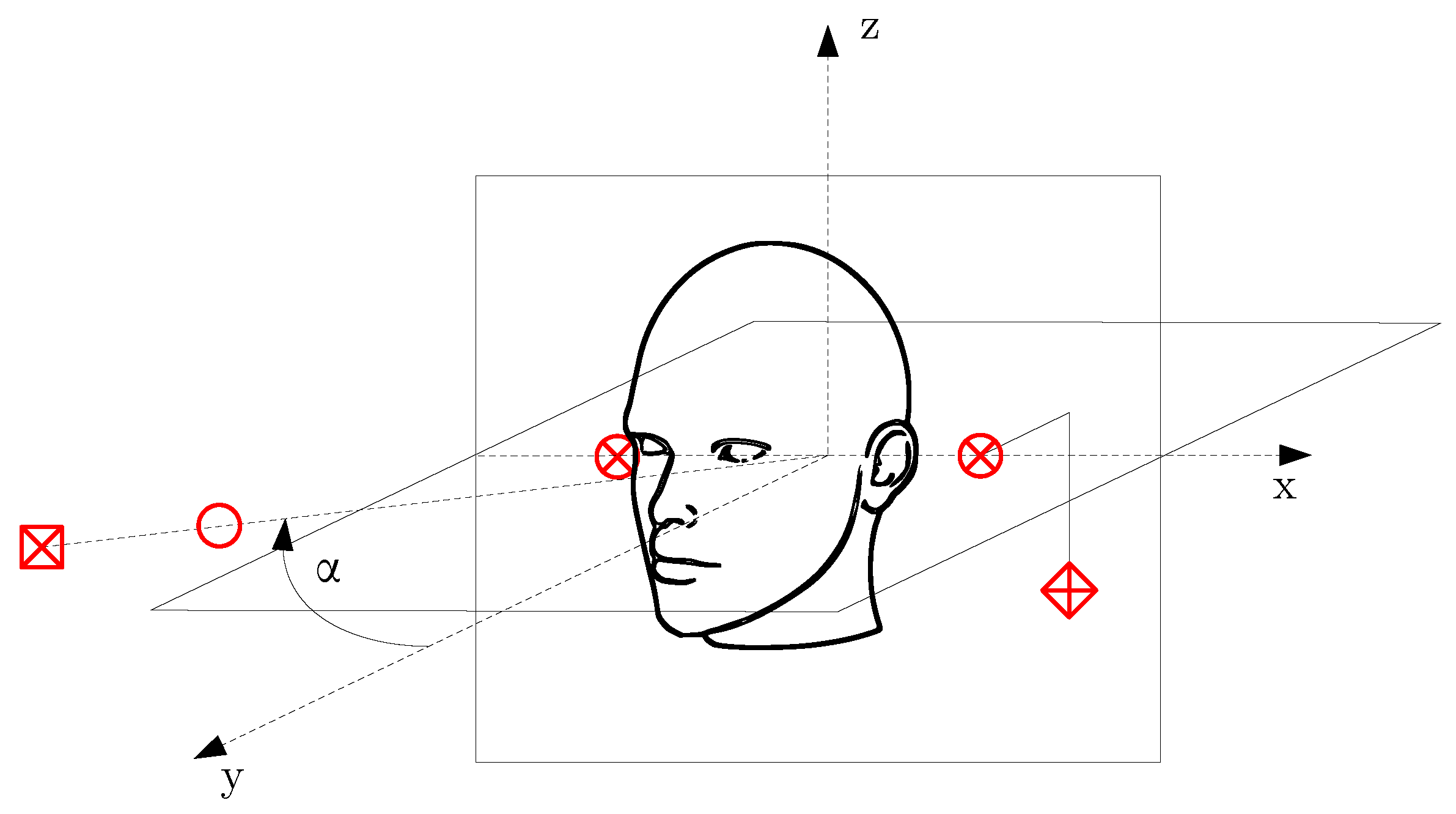
The positions of the sources and the microphones can be seen in Figure 6. The list of symbols can be seen in Figure 2.
Plenty of simulations have been carried out, where the frequency of the noise, the position of the error microphones and the direction of the primary source were the variables. Here, only five simulations are presented. In all the cases introduced here, the distance of the primary source form the chair is 3 m. The simulations cover a 1 m × 1 m area in the x-y and the x-z plane, respectively.
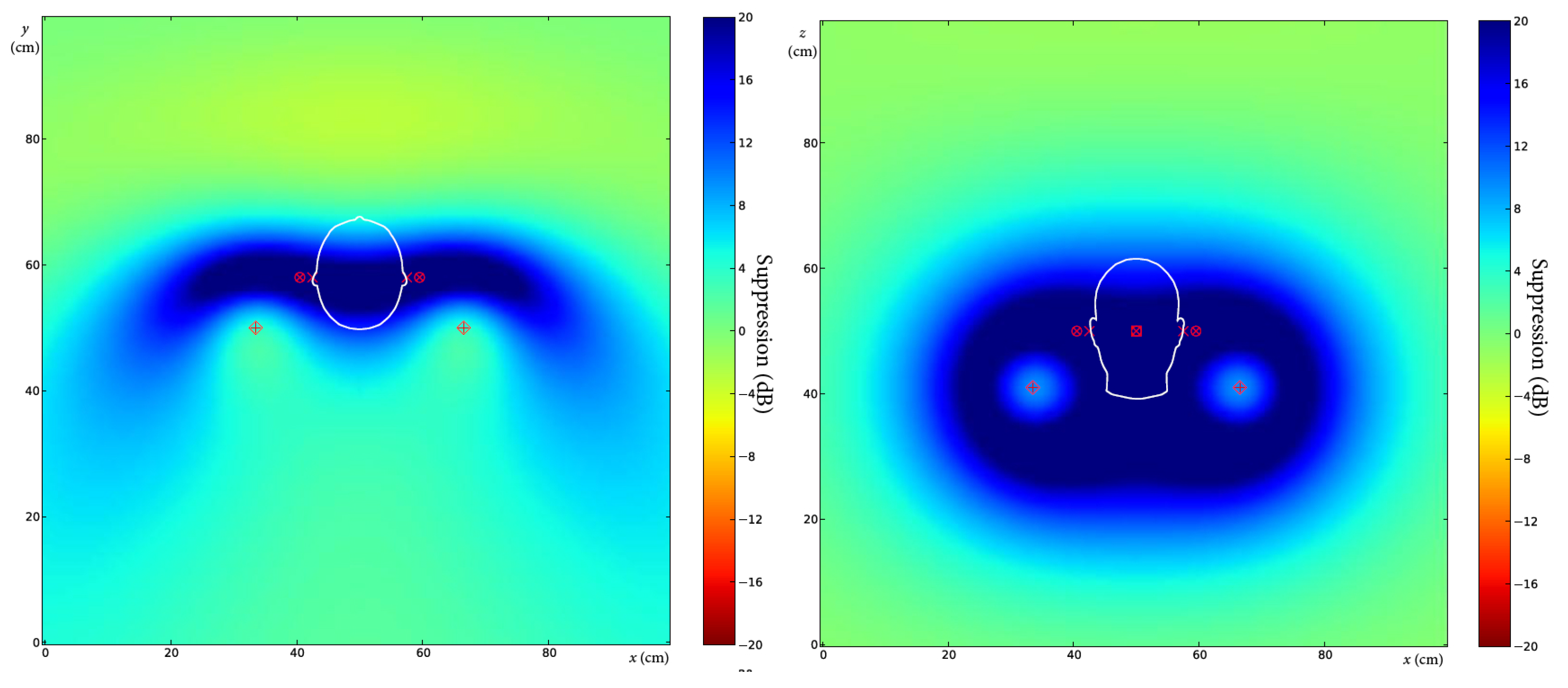
In the first case the frequency of the noise is set to 500 Hz. The error microphones are cm away in the x direction from the ears, while the angle of the primary source is . The result of the simulation can be seen in Figure 7. The pictures show the level of the suppression in the x-y and the x-z plane, and the color bar on the right helps to evaluate the level in dB. The zone of quiet is spread to the entire headrest, so the positions of the error microphones are not crucial.
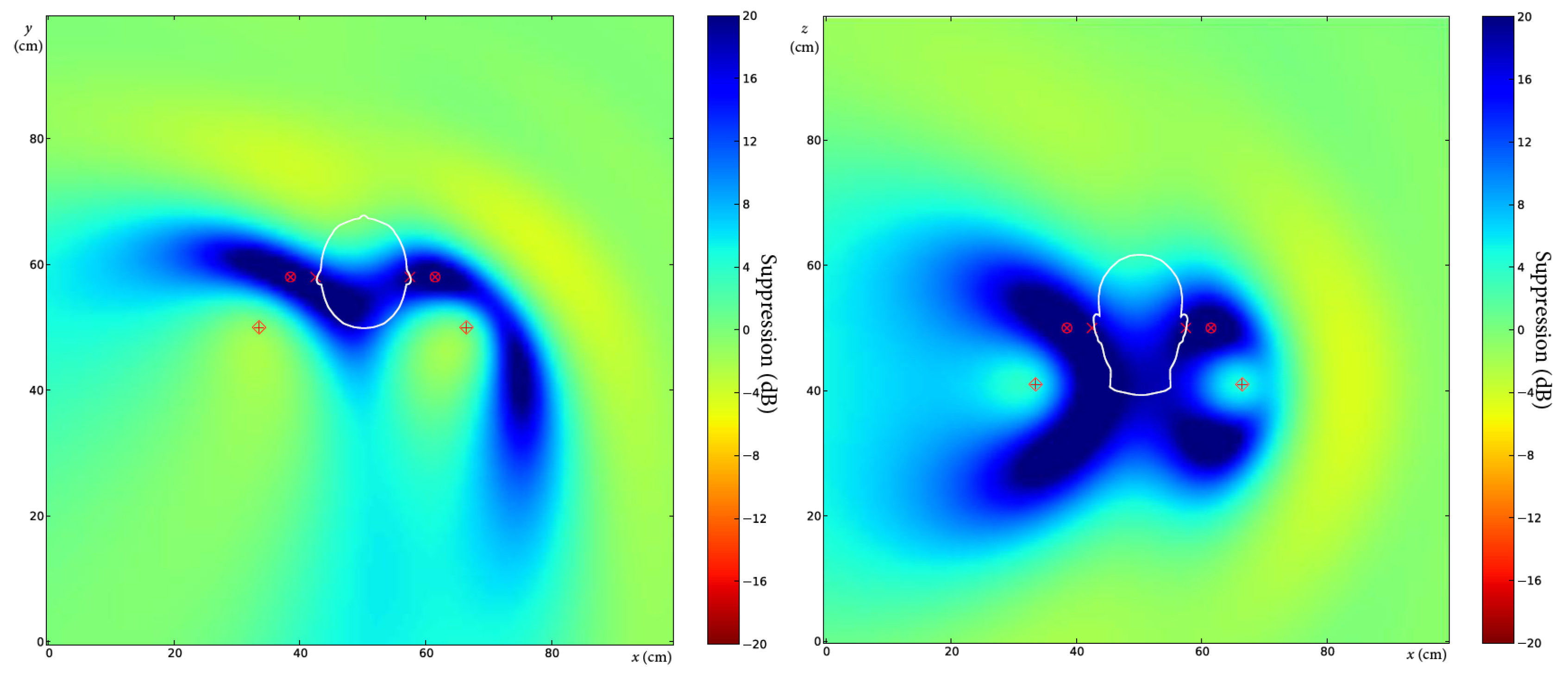
In the following simulations, the frequency of the noise is set to 1 kHz. In the second case, the other settings are the same as above: cm, . The result of the simulation can be seen in Figure 8. The suppression map clearly shows the reduced zone of quiet.
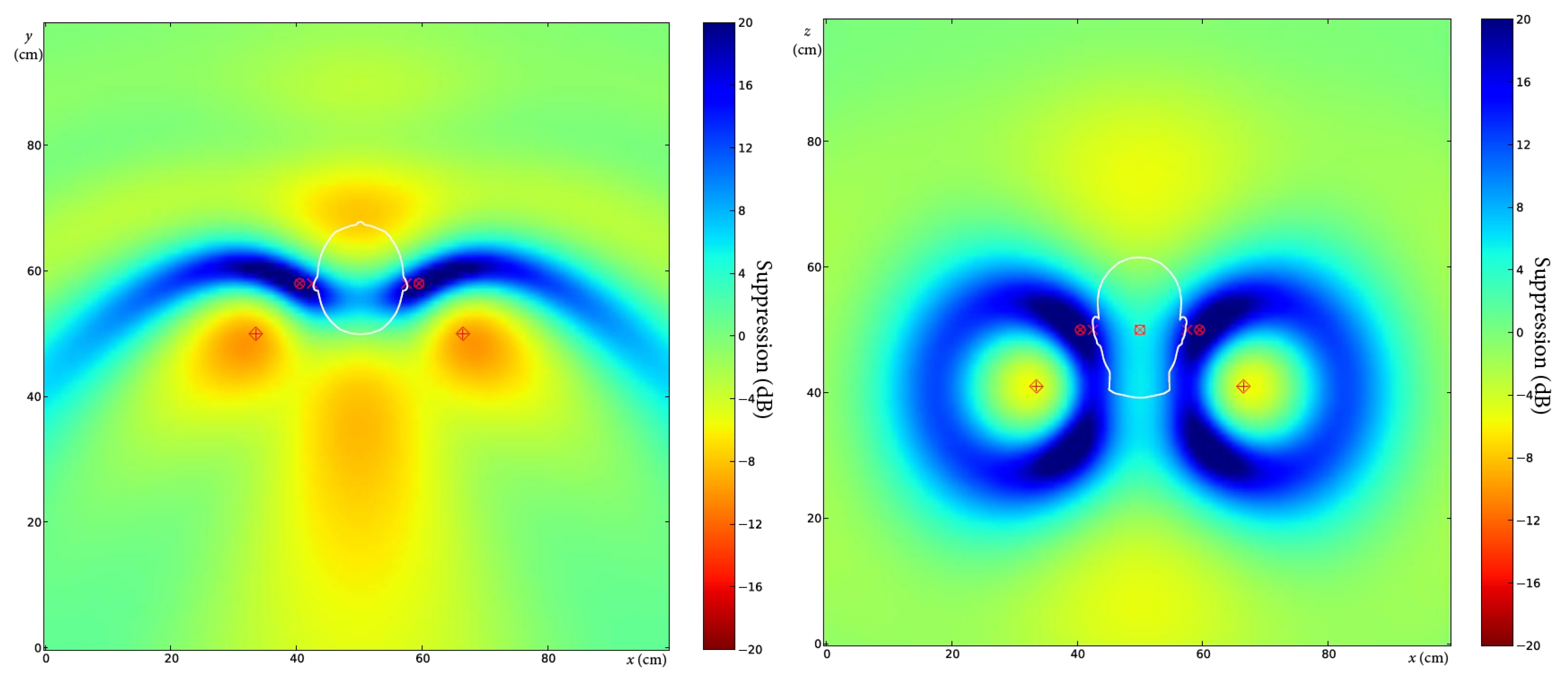
The third simulation deals with a similar arrangement, and the only difference is that the error microphones are cm away from the ears. The result of the simulation can be seen in Figure 9.
In the fourth case, the distance between the error microphones and the ears remains cm, but the angle of the primary source has been changed to . The result of the simulation can be seen in Figure 10.
The fifth simulation shows the suppression map if the primary source is rotated by . The other parameters equal those of the previous case. The result of the simulation can be seen in Figure 11. The simulations where the primary source had different positions show that the ears stay in the zone of quiet.
The above results are also in accordance with the estimation based on a diffuse sound field. If the error microphones are at a distance of 2 cm from the ears, the suppression is much greater than 10 dB. If the distance is increased to 4 cm, the suppression is at least about 10 dB. Both the literature data for diffuse field and our simulations for direct field have shown that significant suppression can be achieved if the microphones are located at a comfortable distance from the ears, which can easily be set using the flexible microphones.
3. Noise-Canceling Chair Design
3.1. Hardware Description
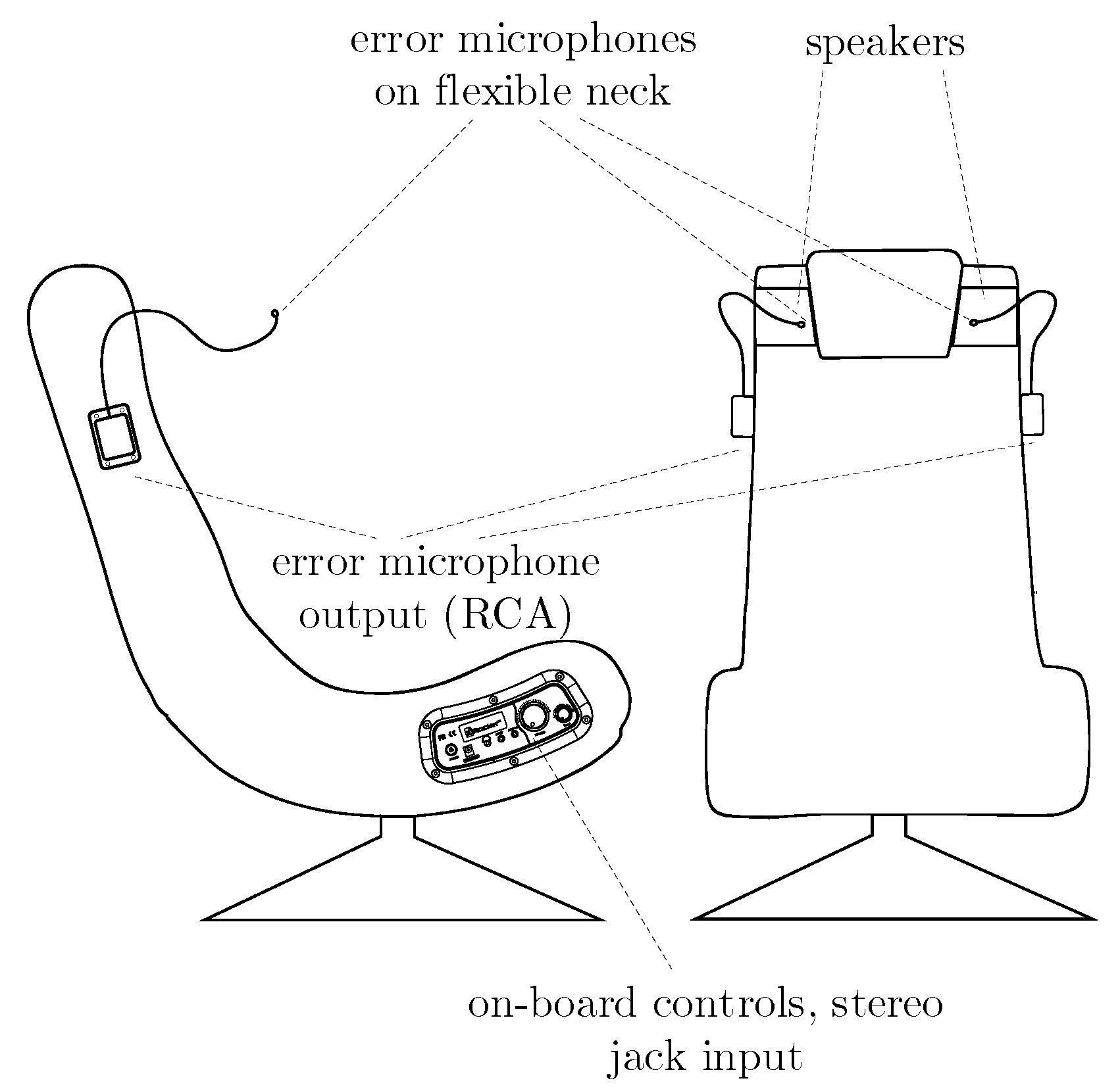
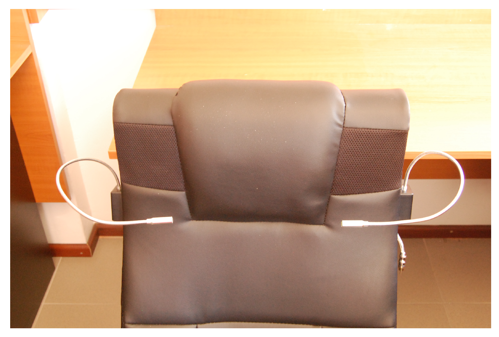
The X Rocker Gaming Chair [13] is the central unit of our noise-canceling system. The sketch of the chair can be seen in Figure 12. The loudspeakers and the power amplifier are built into the chair. There is also a subwoofer at the bottom of the chair, but it has not been used for noise cancellation. There are RCA sockets on the side of the chair to connect the control signals. The error microphones are attached to the chair by flexible stems with a length of 40 cm. Small boxes are fastened to the headrest that hold the stems and the RCA sockets where the output of the microphones is available. A photo of the headrest can be seen in Figure 13.
Based on the preliminary experiments, four reference microphones have been designed that are mounted on small stands like paper-weights. Thus, six microphones of the same type have been used altogether. A simple amplifier has been constructed to replace the high quality studio devices used previously. The block diagram of the system can be seen in Figure 14.
The controller is implemented on an Analog Devices AD21262 signal processor-based [14] hardware developed in our signal processing laboratory for multiple input-multiple output (MIMO) signal processing applications. It is a processor board with an eight-channel AD/DA board attached to it. The analog to digital and digital to analog conversion is performed by four cascaded Analog Devices AD73322 delta-sigma stereo codecs [15] that have low group delay. In the development phase, a JTAG interface has been connected to the board, and the program could be modified, if required. There are some switches on the board that can be used to control the program when the JTAG is not connected to the hardware. The switches can be used, e.g., to choose the identification or the noise control mode.
3.2. Control Algorithm
The noise-canceling chair comprises two loudspeakers and two error microphones. The microphones receive sound from both loudspeakers, so MIMO control had to be designed. Feedforward control with multiple reference signals has been chosen, which would imply the application of the multiple error LMS (MLMS) algorithm [16]. However, the MLMS algorithm and also its original single input–single output version, the filtered-X LMS (XLMS), algorithm suffer from a low convergence rate. Hence, the filtered error LMS (ELMS) algorithm has been implemented [11], which requires less computations, as well. Going forward, it is assumed that the MLMS algorithm is well known; thus, only the ELMS algorithm is presented in detail.
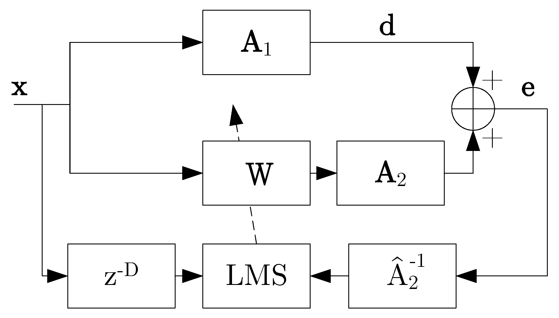
The control loop can be seen in Figure 15. All the signals are vectors, and the transfer functions are matrices. For the sake of convenience, the notations of the time step n and the discrete complex frequency variable z are omitted in the figure.
The reference signal vector results in the primary noise vector , where the primary path is modeled by the matrix . The secondary path is modeled by , which filters the output of the adaptive filters. To each loudspeaker belongs K adaptive filters, where K is the number of reference sensors. Since there are two outputs, the adaptive filter matrix has two rows and K columns. Each adaptive filter has an equal number of coefficients N. In the time domain, the filters’ output can be expressed as follows:
The filter coefficient matrix has two columns, since there are two outputs, and N rows, according to the number of the coefficients. Thus, the vector collects the actual and the previous samples of the k-th reference signal. The output of the controller is the sum of the filters’ outputs for all the reference signals:
The error vector is simply the sum of the primary and the secondary noise in the position of the error microphones:
The adaptation of the control filters’ coefficients is as follows:
where:
The procedure can be easily followed by Figure 15. Instead of filtering the reference signal by the model of the secondary path, as it is usual in the case of the XLMS or the MLMS algorithm, here the error signal is filtered by a particular inverse of the secondary path. If is of non-minimum phase, its exact inverse is unstable. However, the so-called delayed inverse always exists, is stable [11] and can be used for the adaptation. This delay needs to be compensated; this is why is inserted in the reference path. If the delay D is sufficiently high, a common delay for all the filters can be set, which can ease the implementation.
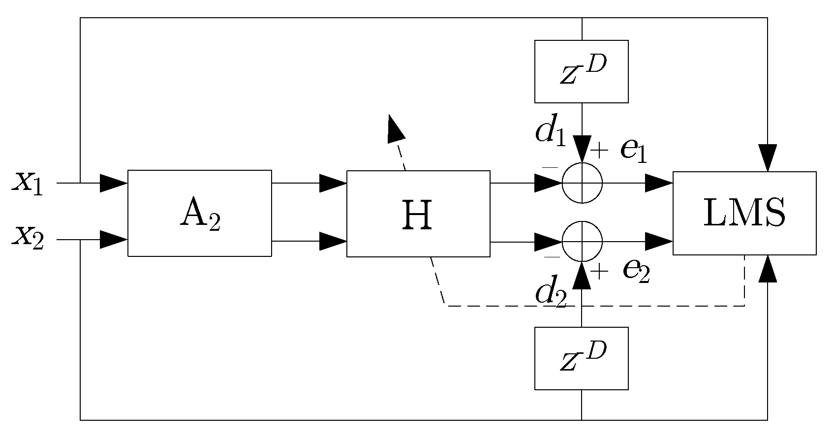
The parameter controls the speed of convergence in the usual way. Although the delayed inverse can be determined by inverting the model of the secondary path, a much simpler procedure is depicted in Figure 16. Here, the vectors are split into scalar signals for the two by two case. Independent random signals and are generated and connected to the loudspeakers. Now, the error microphone signals are the inputs for the adaptive filter matrix . The desired signals for are the delayed versions of and and can be adapted by the simple LMS rule. At the end of the procedure, . The common delay D can be set experimentally.
The general advantage of the ELMS algorithm is the faster convergence compared to the XLMS or MLMS algorithms. The reason for that is the equalization of the adaptation path, as the magnitude response of the delayed inverse is the true inverse of the magnitude response of the secondary path. In our case, the ELMS algorithm is particularly useful, as it requires less computations and needs less memory. In the case of the MLMS algorithm, each reference signal must be filtered four times, and the filters’ outputs are to be stored for the adaptation. In the case of the ELMS algorithm, only the error signals are to be filtered, i.e., only four filtering times are necessary altogether, independent of the number of the reference signals. The memory usage is also more efficient, since there is no need to buffer the differently filtered reference signals, as the same buffer is used for the adaptation for each adaptive filter.
Thus, the final version of the two by two MIMO controller can manage four reference signals with an adaptive filter length of 2000 each, at a sampling frequency of 8 kHz.
4. Experimental Results
The chair has been tested in various environments, and the measurement method was similar to that described in Section 2. This section presents the results of additional experiments carried out in a room.
The test environment was a 5 by 4.3 by 2.8 m room furnished like an office, exhibiting significant reverberation. This room was also located in a multi-story building and had a concrete floor and ceiling and brick wall. Along the longer side, it had a wall-to-wall glass window, on the opposite side a door and a built-in wardrobe made of solid wood. The floor plan with the measurement arrangement can be seen in Figure 17. The area surrounding the chair is depicted in Figure 18. The figure shows the exact positions of the reference and the error microphones. The suppression of the sound had been measured by a dummy head fastened to the headrest, which is also drafted in the figure by a rectangle. The symbols are the same as listed in Figure 2.
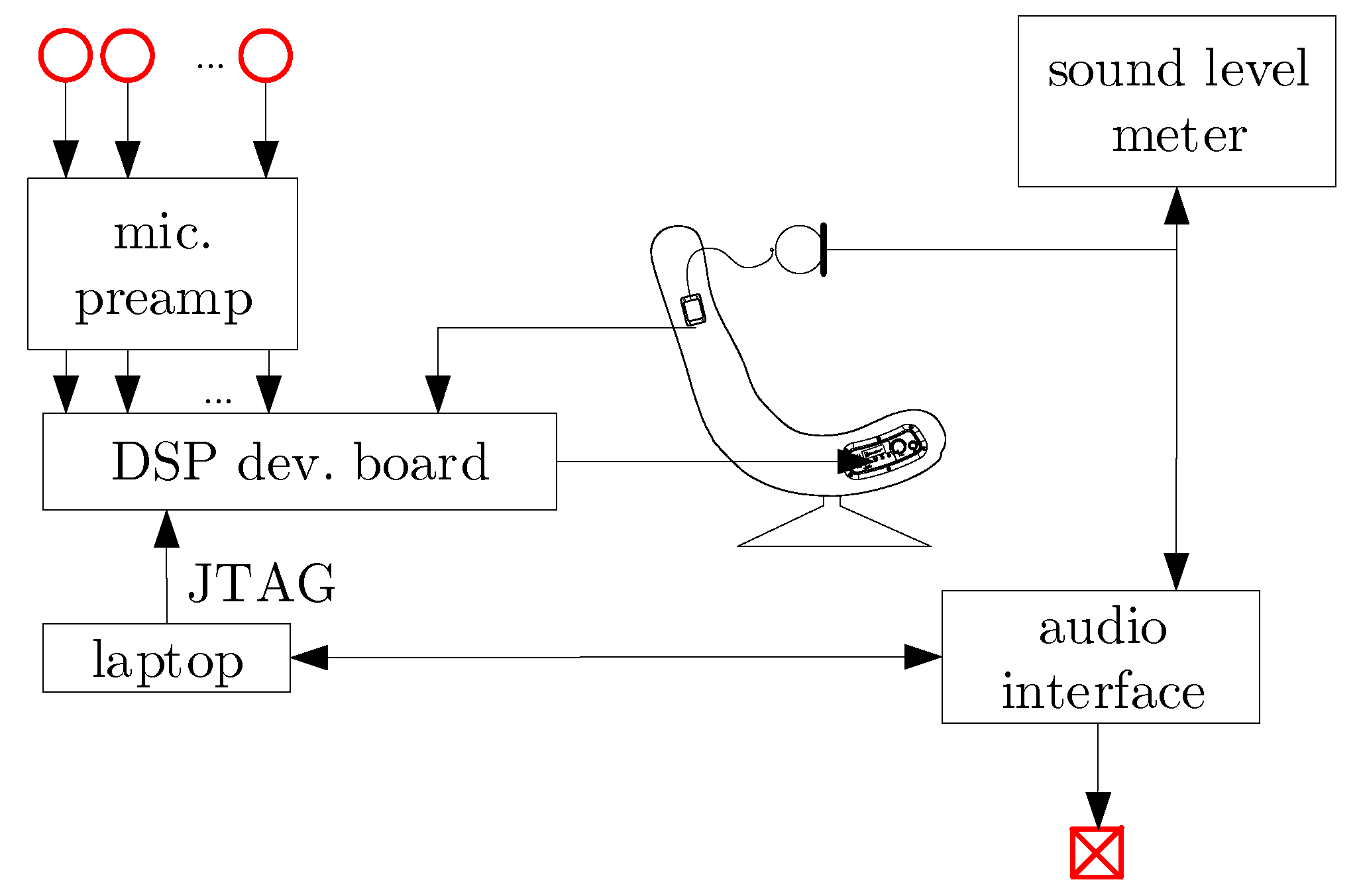
The measurement equipment can be seen in Figure 19. The main components were already described in the previous section. Three reference microphones have been placed on tables, and the overhead one has been placed on a stand. In addition to the chair and the controller, there is a dummy head and a sound level meter. Note that the probe is detachable and has been placed inside the dummy head. A Cakewalk UA-101 USB audio interface has been used to generate the primary noise and simultaneously record the residual noise with a sampling frequency of 44.1 kHz. The suppression has been measured by the sound level meter and by evaluating the records in MATLAB.
The spectra were also calculated, which enabled the evaluation of the control in the frequency domain. The power spectral density (PSD) has been calculated by the fast Fourier transform (FFT) using the Welch method [17]. We used 2048 wide Hamming windows in order to suppress the phenomenon of picket fence and leakage. Five second-long periods have been selected from the records to calculate the spectra for the ‘ANC off’ and the ‘ANC on’ state, respectively.
The measurement results are summarized in Table 3. Although only one setting for the location of the primary source and the reference microphones is introduced here, these parameters are also included in the table. Thus, the test results can be easily compared to those of the preliminary experiments presented in Table 2.
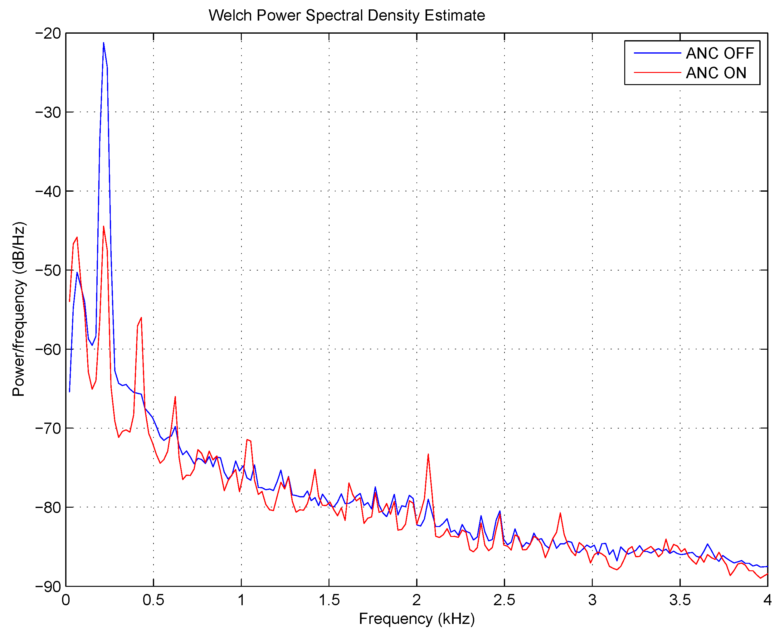
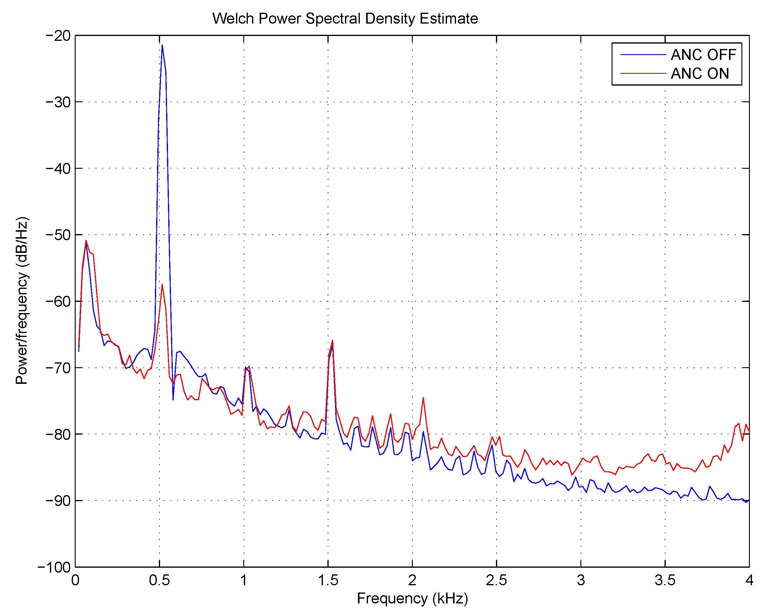
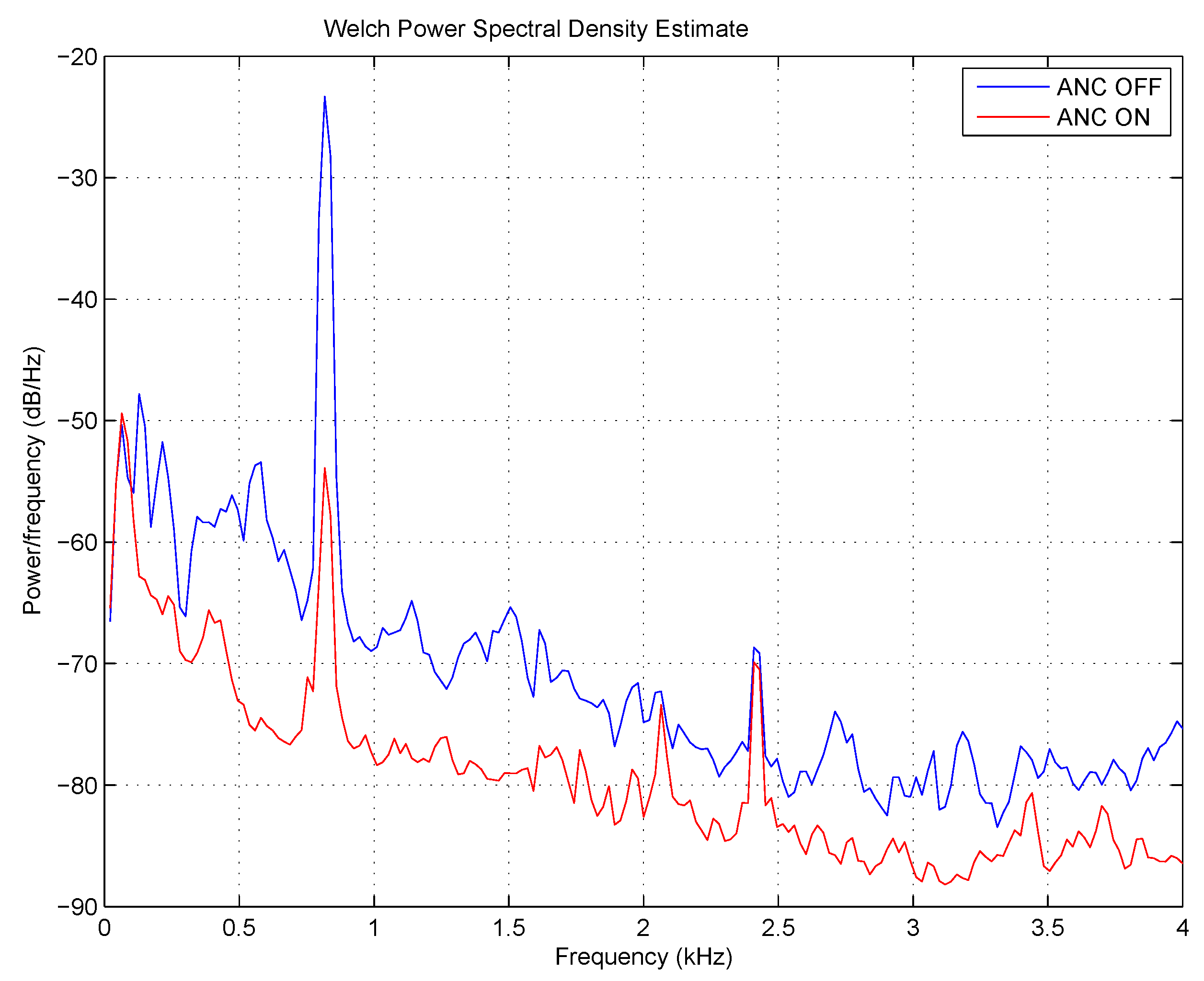
The suppression of the tonal components of 200, 500 and 800 Hz was excellent, as expected. The appropriate spectra can be seen in Figure 20, Figure 21 and Figure 22, respectively. The suppression at a frequency of 200 Hz was slightly worse than the others. In addition, some partials appeared in the spectrum, which indicates the non-linear behavior of the signal path. The phenomenon can be explained by the use of simpler microphone amplifiers that have a high lower cut-off frequency.
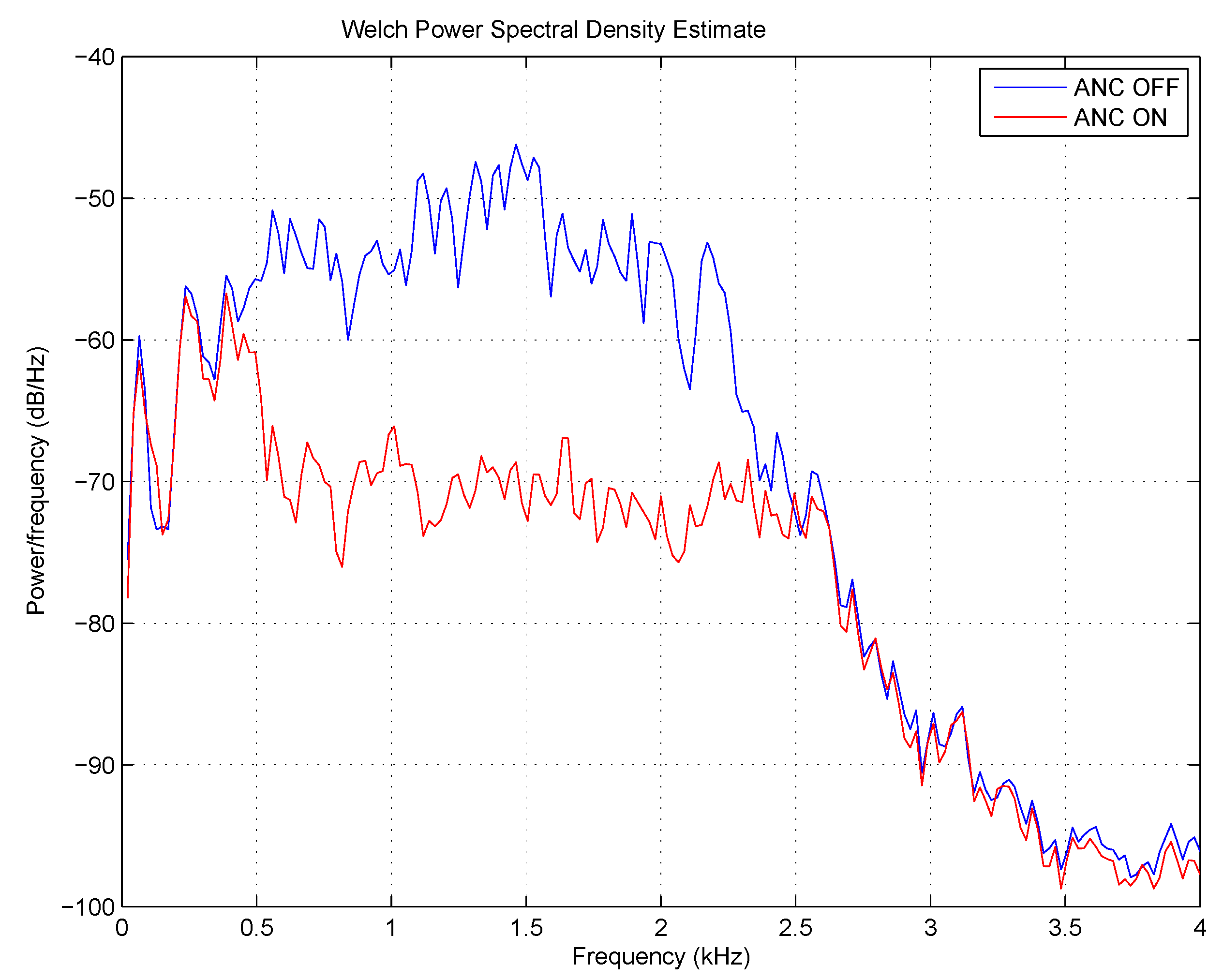
The suppression of the broadband random noise with a bandwidth of Hz was also successful. The spectra can be seen in Figure 23. The controller was able to cancel the noise even above 1 kHz, which is a promising result. Unfortunately, at low frequencies, below about 300 Hz, there was no suppression. This is because of the non-linear amplifiers that deteriorated the correlation between the error signal and the actual sound pressure at the microphones. This phenomenon is in accordance with the moderate suppression of a tonal sound of 200 Hz introduced above.
5. Conclusions
The paper presented a chair equipped with active noise control. Noise-canceling chairs can be the competitors of the well-established active headphones, as their long-time wear is uncomfortable. Several attempts to build such a chair have been reported, often referred to as an active headrest system. Our literature survey has shown that the main development has been focused on the acquisition of the error signals, as the error microphones built into the headrest cannot result in sufficient suppression at the ears. Virtual and remote microphone technology are preferred in active headrests, while the controller is usually unable to cancel broadband noise.
Our intention was to also suppress broadband noise; therefore, feedforward control was chosen. Preliminary experiments have shown that the chair should be surrounded by multiple reference microphones. Such an arrangement is prepared for the cancellation of the primary noise generated at different positions and results in greater suppression, compared to the single reference case. Simulations have proven that physical microphones at a comfortable distance from the ears can provide fairly high suppression.
Then, the construction details of the noise-canceling chair were described. We have used two flexible gooseneck microphones fastened to the headrest. The microphones can be set by the user to the appropriate position. The two loudspeakers are controlled by the signals of the two error microphones and four reference signals. The controller is based on the normalized filtered error least mean squared algorithm, implemented on an Analog Devices ADSP-21262 signal processor-based hardware. The MIMO controller can manage four reference signals with an adaptive filter length of 2000 each, at a sampling frequency of 8 kHz. The application of the ELMS algorithm is justified by its faster convergence, less computational demand and memory usage, compared to the XLMS or MLMS algorithms. In the last section, experimental results were reported that showed the efficient suppression of tonal, as well as broadband disturbances in a moderately damped room.
The development of the noise-canceling chair is not complete, but the results are promising. Application of the remote microphone technique besides the proposed multiple reference control and the utilization of wireless reference microphones are subjects of further research.
Author Contributions
Conceptualization, L.S.; Methodology, L.S.; Software, A.S.; Validation, L.S., and A.S.; Investigation, L.S.; Supervision, L.S.; Writing-original draft, L.S., and A.S.
Funding
The research was co-sponsored by the EU and Hungary under the project GOP-1.3.1-11/C-2012-0054 and carried out by Euronet Inc.
Conflicts of Interest
The authors declare no conflict of interest.
Abbreviations
The following abbreviations are used in this manuscript:
| AD | Analog to digital |
| ANC | Active noise control |
| DA | Digital to analog |
| ELMS | Filtered error least mean squared |
| FFT | Fast Fourier transform |
| JTAG | Joint Test Action Group |
| LMS | Least mean squared |
| MIMO | Multiple input-multiple output |
| MLMS | Multiple error least mean squared |
| PSD | Power spectral density |
| RMT | Remote microphone technique |
| XLMS | Filtered reference least mean squared |
| VMT | Virtual microphone technique |
References
- Kuo, S.M.; Morgan, D.R. Active noise control: A tutorial review. Proc. IEEE 1999, 87, 943–973. [Google Scholar] [CrossRef]
- Kajikawa, Y.; Gan, W.-S.; Kuo, S.M. Recent advances on active noise control: Open issues and innovative applications. APSIPA Trans. Signal Inf. Proc. 2012, 1, 1–21. [Google Scholar] [CrossRef]
- Sennheiser PXC-450 Data Sheet. Available online: https://en-au.sennheiser.com/pxc450 (accessed on 28 August 2018).
- Pawelczik, M. Adaptive noise control algorithms for active headrest system. Control Eng. Pract. 2004, 12, 1101–1112. [Google Scholar] [CrossRef]
- Das, D.P.; Moreau, D.J.; Cazzolato, B. Performance evaluation of an active headrest using the remote microphone technique. In Proceedings of the Acoutics 2011, Gold Coast, Australia, 2–4 November 2011. Paper No. 69. [Google Scholar]
- Siswanto, A.; Chang, C.-Y.; Kuo, S.M. Active noise control of headrests. In Proceedings of the 2015 Asia-Pacific Signal and Information Processing Association Annual Summit and Conference (APSIPA), Hong Kong, China, 16–19 December 2015; pp. 688–692. [Google Scholar]
- Treyer, D.; Germann, S.; Siegenthaler, M. Silence is golden—Implementation of a noise-canceling office chair. In Proceedings of the Inter-Noise 2016, Hamburg, Germany, 21–24 August 2016; pp. 3027–3038. [Google Scholar]
- Jung, W.; Elliott, S.J.; Cheer, J. Combining the remote microphone technique with head-tracking for local active sound control. J. Acoust. Soc. Am. 2017, 142, 298–307. [Google Scholar] [CrossRef] [PubMed] [Green Version]
- Elliott, S.J.; Elliott, S.J.; Bonilha, M. Active cancellation at a point in a pure tone diffuse sound field. J. Sound Vib. 1988, 120, 183–189. [Google Scholar] [CrossRef]
- Moreau, D.; Cazzolato, B.; Zander, A.; Petersen, C. A review of virtual sensing algorithms for active noise control. Algorithms 2008, 1, 69–99. [Google Scholar] [CrossRef]
- Widrow, B.; Walach, E. Adaptive Inverse Control; Prentice-Hall, Inc.: Upper Saddle River, NJ, USA, 1996; ISBN 9780130059680. [Google Scholar]
- Cheng, C.I.; Wakefield, G.H. Introduction to head-related transfer functions (HRTFs): Representations of HRTFs in time, frequency, and space. J. Audio Eng. Soc. 2001, 49, 231–249. [Google Scholar]
- Ace Bayou X Rocker 5127401 Pedestal Video Gaming Chair. Available online: https://www.amazon.com/Ace-Bayou-5127401-Pedestal-Wireless/dp/B006NZGN0W (accessed on 28 August 2018).
- Analog Devices ADSP 21262 Digital Signal Processor Data Sheet. Available online: http://www.analog.com/media/en/technical-documentation/data-sheets/ADSP-21261_21262_21266.pdf (accessed on 28 August 2018).
- Analog Devices AD 73322 Dual Voiceband Codec. Available online: http://www.analog.com/media/en/technical-documentation/data-sheets/AD73322.pdf (accessed on 28 August 2018).
- Elliot, S.J.; Stothers, I.M.; Nelson, P.A. A multiple error LMS algorithm and its application to the active control of sound and vibration. IEEE Trans. Acoust. Speech Signal Proc. 1987, 35, 1423–1434. [Google Scholar] [CrossRef]
- Welch, P.D. The use of fast Fourier transform for the estimation of power spectra: A method based on time averaging over short, modified periodograms. IEEE Trans. Audio Electroacoust. 1967, 15, 70–73. [Google Scholar] [CrossRef]
Figure 1.
Measurement arrangement in the classroom.

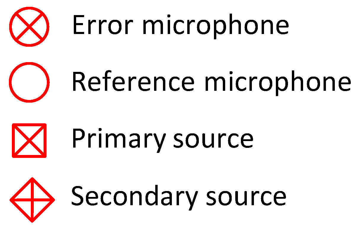
Figure 2.
List of symbols used for the objects of the simulation.

Figure 3.
Arrangement of the reference microphones.

Figure 4.
Control equipment for the preliminary experiments.

Figure 5.
Position of the secondary sources relative to the head.

Figure 6.
Positions of the sources and the microphones relative to the head.

Figure 7.
Result of the first simulation. Hz, cm, . Left plot: x-y view. Right plot: x-z view.

Figure 8.
Result of the second simulation. kHz, cm, . Left plot: x-y view. Right plot: x-z view.

Figure 9.
Result of the third simulation. kHz, cm, . Left plot: x-y view. Right plot: x-z view.

Figure 10.
Result of the fourth simulation. kHz, cm, . Left plot: x-y view. Right plot: x-z view.

Figure 11.
Result of the fifth simulation. kHz, cm, . Left plot: x-y view. Right plot: x-z view.

Figure 12.
Sketch of the noise-canceling chair.

Figure 13.
Photo of the headrest with the error microphones.

Figure 14.
Block diagram of the chair with the controller.

Figure 15.
Filtered error least mean squared (ELMS) algorithm.

Figure 16.
Identification of the secondary path for the ELMS algorithm. Illustration for the two by two case.
Figure 16.
Identification of the secondary path for the ELMS algorithm. Illustration for the two by two case.

Figure 17.
Measurement arrangement in the office.

Figure 18.
Detailed map of the neighborhood of the chair.

Figure 19.
Control equipment for the test experiments.

Figure 20.
Power spectral density of a tonal sound of 200 Hz at the measurement point. Blue line: control off. Red line: control on.
Figure 20.
Power spectral density of a tonal sound of 200 Hz at the measurement point. Blue line: control off. Red line: control on.

Figure 21.
Power spectral density of a tonal sound of 500 Hz at the measurement point. Blue line: control off. Red line: control on.
Figure 21.
Power spectral density of a tonal sound of 500 Hz at the measurement point. Blue line: control off. Red line: control on.

Figure 22.
Power spectral density of a tonal sound of 800 Hz at the measurement point. Blue line: control off. Red line: control on.
Figure 22.
Power spectral density of a tonal sound of 800 Hz at the measurement point. Blue line: control off. Red line: control on.

Figure 23.
Power spectral density of broadband noise at the measurement point. Blue line: control off. Red line: control on.
Figure 23.
Power spectral density of broadband noise at the measurement point. Blue line: control off. Red line: control on.


Table 1.
Parameters of the experiments and their settings.
| Parameter | Settings |
|---|---|
| Positon of primary source | see Figure 1 |
| Number of reference microphones | 1, 2, 3, 4, 6 |
| Position of reference microphones | see Figure 3, triangle, tetrahedron, hexagon |
| Radius of reference microphones (m) | 0.5, 1, 2 |
| Number of control filter taps | variable |
Table 2.
Noise control results obtained in the preliminary experiments.
| Position of Primary Source | Number of Ref. Microphones | Position of Ref. Microphones | Number of Control Filter Taps | Suppression (dBA) |
|---|---|---|---|---|
| P1 | 1 | front | 1000 | 1.5 |
| 4000 | 3.0 | |||
| 8000 | 3.0 | |||
| 2 | front, back | 1000 | 4.5 | |
| 4000 | 8.5 | |||
| up, down | 1000 | 4.0 | ||
| 4000 | 6.0 | |||
| 3 | front, left, right | 1000 | 7.0 | |
| 2700 | 9.0 | |||
| 4 | front, back, left, right | 1000 | 10.5 | |
| 2000 | 15.0 | |||
| 6 | cube | 1000 | 15.0 | |
| 1300 | 16.0 | |||
| P2 | 1 | front | 1000 | 2.0 |
| 4000 | 3.5 | |||
| 8000 | 3.5 | |||
| 2 | front, back | 1000 | 3.0 | |
| 4000 | 7.0 | |||
| up, down | 1000 | 4.5 | ||
| 4000 | 7.5 | |||
| 3 | front, left, right | 1000 | 8.0 | |
| 2700 | 13.0 | |||
| 4 | front, back, left, right | 1000 | 10.0 | |
| 2000 | 14.0 | |||
| 6 | cube | 1000 | 13.5 | |
| 1300 | 14.5 |
Table 3.
Noise control results obtained in the tests.
| Position of Primary Source | Number of Ref. Microphones | Position of Ref. Microphones | Primary Noise | Number of Control Filter Taps | Suppression (dBA) |
|---|---|---|---|---|---|
| P | 4 | See Figure 18 | sine, 200 Hz | 2000 | 20.4 |
| sine, 500 Hz | 2000 | 29.7 | |||
| sine, 800 Hz | 2000 | 28.2 | |||
| broadband, | |||||
| Hz | 2000 | 16.2 |
© 2018 by the authors. Licensee MDPI, Basel, Switzerland. This article is an open access article distributed under the terms and conditions of the Creative Commons Attribution (CC BY) license (http://creativecommons.org/licenses/by/4.0/).
Share and Cite
MDPI and ACS Style
Sujbert, L.; Szarvas, A. Noise-Canceling Office Chair with Multiple Reference Microphones. Appl. Sci. 2018, 8, 1702. https://0-doi-org.brum.beds.ac.uk/10.3390/app8091702
AMA Style
Sujbert L, Szarvas A. Noise-Canceling Office Chair with Multiple Reference Microphones. Applied Sciences. 2018; 8(9):1702. https://0-doi-org.brum.beds.ac.uk/10.3390/app8091702
Chicago/Turabian StyleSujbert, László, and Attila Szarvas. 2018. "Noise-Canceling Office Chair with Multiple Reference Microphones" Applied Sciences 8, no. 9: 1702. https://0-doi-org.brum.beds.ac.uk/10.3390/app8091702
Note that from the first issue of 2016, this journal uses article numbers instead of page numbers. See further details here.