Article

Ultrasonic-Assisted Cutting: A Beneficial Application for Temperature, Torque Reduction, and Cutting Ability Improvement in Deep Drilling of Al-6061

Thainguyen University of Technology, 3/2 Street, Tich Luong Ward, Thai Nguyen 250000, Vietnam
*
Author to whom correspondence should be addressed.
Submission received: 28 August 2018 / Revised: 14 September 2018 / Accepted: 14 September 2018 / Published: 20 September 2018
(This article belongs to the Special Issue Fishery Acoustics, Applied Sciences and Practical Applications)

Abstract

:
This paper presents an experimental study of the positive effects of vibration-assisted deep drilling of aluminum alloy Al-6061. The four most important evaluation criteria in drilling—machinability, workpiece temperature, torque, and material removal rate—were chosen to be investigated. Holes with a depth-to-diameter ratio of 13 were drilled by high speed steel (HSS) twist drill bits of 3 mm diameter, using both methods of conventional drilling (CD) and ultrasonic-assisted drilling (UAD). Three levels of axial force of 6 kgf, 9 kgf, and 12 kgf were kept constant for each pair of comparison experiments. It was found that workpiece temperature and torque not only changed from one drill to the other, but were also dependent on the hole depth being drilled. Comparisons were made in-pair between CD and UAD under the same axial force and at the same order of hole numbers. The result shows that the material removal rate with UAD was up to 3.5 times higher than that with CD and the average workpiece temperature and torque in UAD were reduced by 3.5 and 6 times, respectively. Moreover, tool life in UAD was observed to increase from 2.5 to 5 times, in terms of number of holes drilled, compared to that in CD.

1. Introduction

Aluminum and its alloys are considered one of the easiest machining materials. However, these materials are difficult to drill with conventional drilling (CD) due to their ductility and softness causing persistent elongated contact with cutting edges and flutes. Several methods such as using a special tool geometry, coating tool, or even reducing the material removal rate (MRR), etc., have been employed to deal with such problems. Recently, a promising technique well known as vibration-assisted machining (VAM) has been reported to overcome problems of drilling difficult-to-cut materials, including aluminum and its alloys. Compared with CD, there have been significant improvements shown in thrust force, burr size, tool wear, noise reduction, and surface finish, etc., from ultrasonic-assisted drilling (UAD). However, other advantages of UAD, such as reducing torque and cutting temperature—the most two important factors which may break the process or shorten the tool life—have not been reported so far. Overall, the improved cutting machinability of aluminum in UAD and the causes behind this phenomenon have also been rather limited in the literature. The purpose of this paper is to deal with these problems.
Recently, ultrasonic-assisted drilling of aluminum and its alloys has been an attractive field of study. In a remarkable study by Amini et al. [1], an experimental comparison between CD and UAD processes for Al-2024-T6 was carried out. The result shows that all investigated terms including thrust force, morphology chip, built-up edge, exit burr, and hole oversize from UAD were reported as significantly improved compared with those from CD. In research by Chang and Bone [2], the authors predicted and compared thrust force induced in UAD and CD of Al-6061-T6. The conclusion shows that there is a vibration frequency that minimizes thrust force in different drills and cutting conditions. Burr height reduction of up to 85%, tool life increase (in terms of number of holes drilled), and an up to 20% reduction in the thrust force of UAD compared with those of CD have also been revealed in another study by these authors [3]. In other investigation, Li et al. [4] found that the thrust force of UAD is much smaller than that of CD, with a larger vibration amplitude resulting in the smaller thrust force of the cutting edge. A study by Babitsky et al. [5] verified several improvements in machining characteristics due to UAD in drilling, including faster penetration rates, reduction of tool wear, surface finish, roundness and straightness of holes, and the reduction or complete elimination of burrs when drilling ductile plates. Nevertheless, the effectiveness of UAD in deep hole drilling of aluminum alloys, where the depth-to-diameter ratios are larger than 5, have rarely been found in the literature.
Investigations considering the reduction of torque and temperature as a primary factor which leads to major improvements in UAD compared with CD of other materials have also been limited in the literature. An experimental study from Azarhoushang and Akbari [6] drilling Inconel 738-LC considered on improvement in average surface roughness and circularity, hole oversize, and drill skidding, causing discontinuous and finer chips in UAD in contrast to in CD. Advantages of UAD such as reducing the thrust force and the cutting torque, causing less burning to the cutter and prolonging the tool life, have been suggested and need to be further validated. Baghlani et al. [7] showed that producing smaller chips was a main effect of UAD for Inconel 738LC superalloy. A study by Sanda et al. [8] on drilling carbon fibre reinforced plastics (CFRP) revealed that UAD resulted in lower thrust forces (up to 30%) and lower surface roughness than did CD, especially for low feeds and cutting velocities. Recently, Baghlani et al. [9] found that a 40% reduction in thrust force can be achieved with UAD Inconel 738LC as opposed to CD. In research by Vakili Azghandi et al. [10], the authors summarized that the average thrust force in UAD was approximately 60% lower than that in CD. In higher cutting speeds in CD, the temperature was elevated dramatically, caused high tool wear owning to the abrasive phase of Cr in the workpiece. Work by Gupta et al. [11] revealed that UAD produced 36% lower thrust force with a chisel edge, similar torque, and 35% lower wear on the chisel edge compared with CD. In another study, Dahnel et al. [12] concluded that UAD of carbon fiber composite and titanium alloy stacks resulted in lower tool wear and thrust forces than did CD at all cutting speeds. Farrukh Makhdum et al. [13] obtained a significant reduction in drilling forces (thrust force and torque), often in excess of 80% when compared with a dry conventional drilling (CD) process. The temperature in the process zone in UAD was higher than that in CD. A numerical investigation by Vaibhav et al. [14] indicated that low feed rates (<150 mm/min) and high cutting speeds (>600 rpm) are ideal for drilling carbon/epoxy laminates for a certain range of drill parameters. Experimental results in the work by Wang et al. [15] showed a significant reduction of the cutting heat in the drilling of cortical bone. In a similar work from Alam et al. [16], the authors revealed that the penetration force and torque dropped significantly in UAD, and improvement of chip removal from the drilling site was observed. In conventional drilling, Ke et al. [17] recommended that the increase of drilling forces, especially the drilling torque, should be avoided because it is likely to break the drill. A modeling and experimental study by Matthew Bono and Jun Ni addressed thermal expansion of the drill as the dominant effect, leading to oversized holes with diameters that increase with depth.
This paper presents another approach to gain insight into the mechanism providing the benefits of UAD over CD. The reduction of torque and temperature was confirmed and then considered as a major cause of the improved machinability, elongated tool life, and increased material removal rate. Friction reduction under vibration would be the original mechanism behind all benefits of UAD and is to be further confirmed.

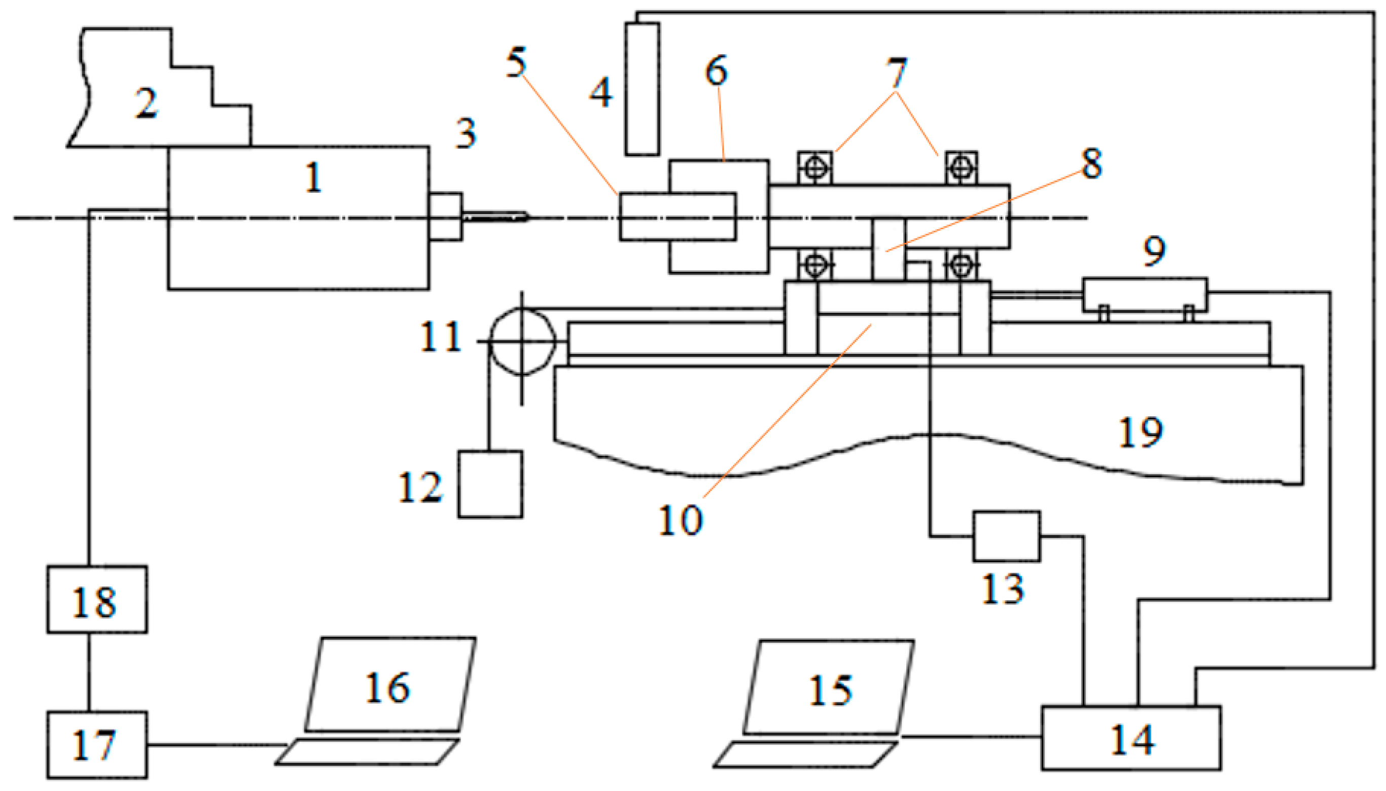
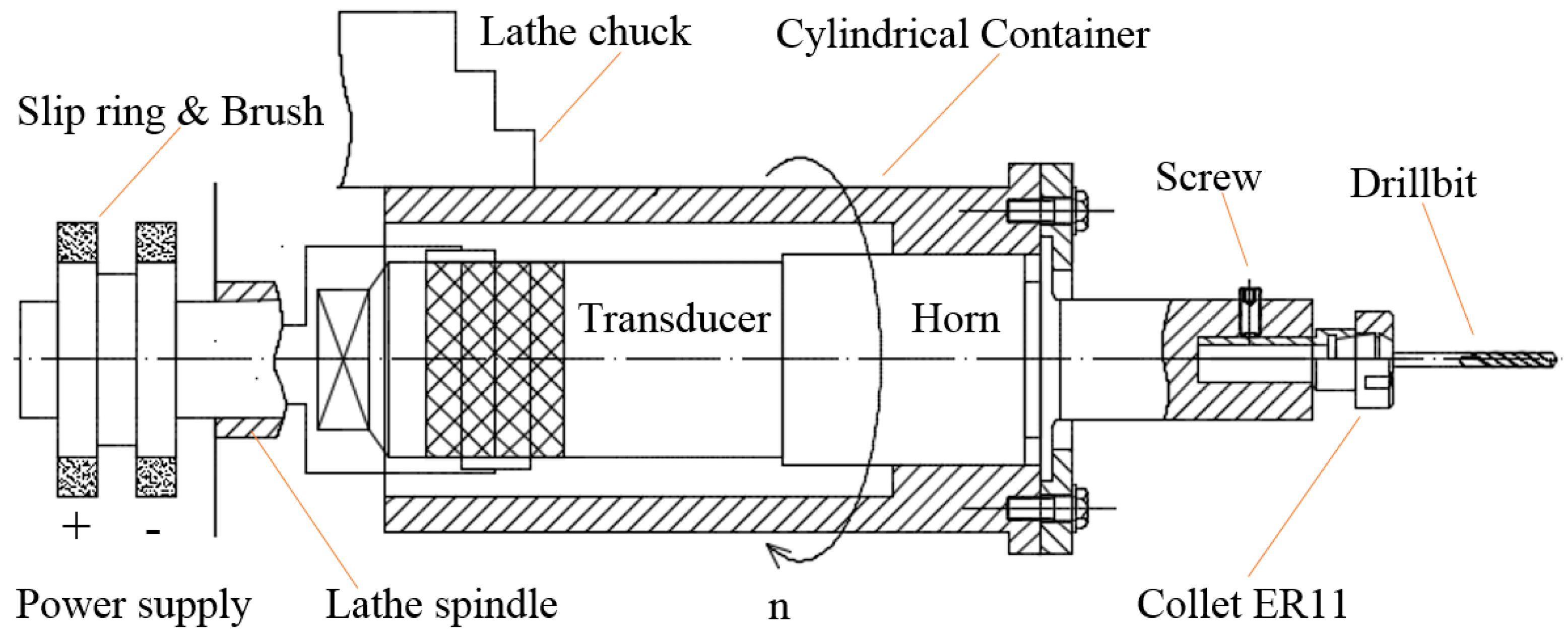
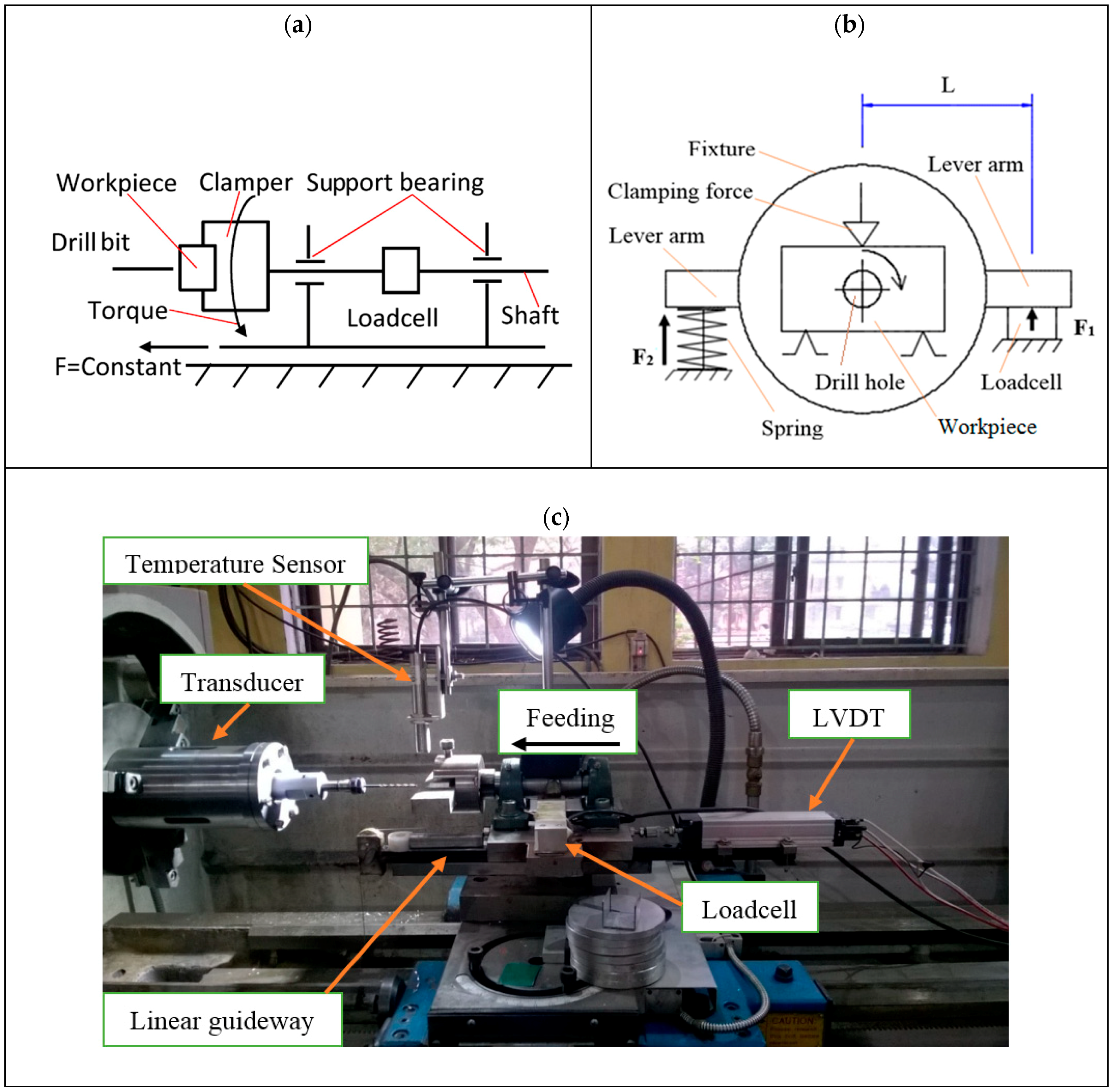
2. Experimental Setup

2.1. Experimental Setup

Figure 1 shows the schema of the experimental setup.
As shown in Figure 1, a rotary UAD (1) set was clamped onto the three-jaw chuck (2) of a lathe machine. The drill bit (3) was clamped in a collet placed inside the rotary UAD. The aluminum workpiece (5) was fixed on a special fixture which can slide along the axial direction of the lathe spindle. The special fixture (6) had a shaft and bearings (7) constrained by a loadcell (8) permitting measure drilling torque. The feeding motion of the drilling process was implemented by means of static gravity from a preset mass (12) via a roller (11). Under the gravity load, the fixture carrying the workpiece tends to move towards the tool. At the beginning of each test, the static load was gently applied to the experimental sample until the sample contacted with the tool. The lathe was then turned on, the mass released, and the drilling process started. The workpiece displacement was measured by a linear displacement transducer (LVDT) (9). A loadcell (10) was arranged in a special way to measure the cutting torque. The signal from the loadcell was amplified by a signal conditioner (13). A noncontact infrared temperature sensor (4), model IRTP-300LS, with a measuring range of 0–300 degrees Celsius was placed near the workpiece to capture the temperature of the workpiece. Data from the LVDT (9), loadcell (10), and temperature sensor (4) were collected by a data acquisition system (DAQ) (14) and then stored in a computer (15). Another computer (16) was used to control a power ultrasonic generator (17). A powered ultrasonic wave was then applied to the transducer inside the rotary VAD via a copper commutator brush (18).
Figure 2 presents the construction of the experimental rotary UAD device. A commercial ultrasonic welding transducer including a proper horn and booster was fitted into a self-made steel tube and clamped at the node of the transducer. The horn was modified by making a hole to put a commercial collet inside. The drill bit was clamped inside the collet. Steady electrical impulses were supplied to the transducer via a copper brush which was positioned at the end of and rotated along with the lathe spindle. Using this arrangement, the drill bit simultaneously received both rotation (from the lathe spindle) and longitudinal vibration (from the transducer).
As mentioned above, the fixture used in this study was designed and fabricated in a special arrangement and thus can provide axial motion and allow us to measure drilling torque. This structure is illustrated in Figure 3.
As shown in Figure 3a, the workpiece was clamped at one end of a shaft supported by a pair of rolling bearings. The shaft tends to rotate when a small amount of torque is applied to the workpiece. A loadcell was used as a barrier to prevent the rotational tendency of the shaft. The value of force acting on the loadcell was used to carry out the corresponding torque by multiplying the force value by the arm length. A spring support was positioned in the opposite side of the shaft in order to create an initial force on the loadcell as indicated in Figure 3b, thus keeping the loadcell always in contact with the shaft. The bearing support, loadcell, and spring support were placed on a thick steel plate. The plate was then fixed on a linear bearing slider. The slider was fixed on the lathe carriage.

2.2. Experimental Operations

Three experimental sets were implemented, corresponding to the three levels of constant axial force of 6 kgf, 9 kgf, and 12 kgf. At each value of axial force, there were two subsets: one for conventional drilling and another for ultrasonic-assisted drilling. Each subset used a new drill bit to make 5 holes on 5 samples. The bit totally lost its cutting ability after producing 5 holes in CD. Thus, each experimental subset includes 5 CD holes and 5 UAD holes. The experimental parameters are presented in Table 1, where the spindle speed was chosen as a typical value for drilling aluminum alloys.
In all tests with UAD, frequency and amplitude were kept constant at 20.188 KHz and 15 µm, respectively. The frequency was experimentally found by using the auto-adjust function on the ultrasonic generator. The amplitude of 15 µm was obtained as the maximum value from the transducer.
Firstly, a prepared mass with proper weights, including 6 kgf, 9 kgf, or 12 kgf, was hung on the end of the rope. A stop was placed between the fixture and the roller to prevent the fixture moving forward. The workpiece was then clamped on the fixture by using an M10 bolt. Two Bakelite sheets were used to insulate the workpiece from the fixture, preventing heat transfer from the workpiece to other parts of the fixture. After turning on the lathe, a manual effort was applied to release the stop and decelerate the fixture motion such that the workpiece came into contact with the tools smoothly. At the instant when the tool contacted with the workpiece, the fixture was totally released, and then the drill process started. It was assumed that all new drill bits have the same cutting capability. In order to consider the effects of the reduction in cutting ability of the tool on cutting performance, experimental data were labeled corresponding to the order of the holes being drilled. Hole number 1 is the first hole produced by a new drill bit and, correspondingly, holes numbered from 2 to 5 are the next holes drilled by the same tool. All signals from the LVDT, loadcell, and temperature sensor were captured, stored, and analyzed. Data from CD and UAD were compared in pairs of holes with the same number order. Calibrated validations were made for all measuring devices used in the test. The LVDT was calibrated by comparing the distance with commercial calipers with a resolution of 0.02 mm. The thermal sensor was checked with a GIM 3590 commercial infrared thermometer from Greisinger.

3. Results and Discussions

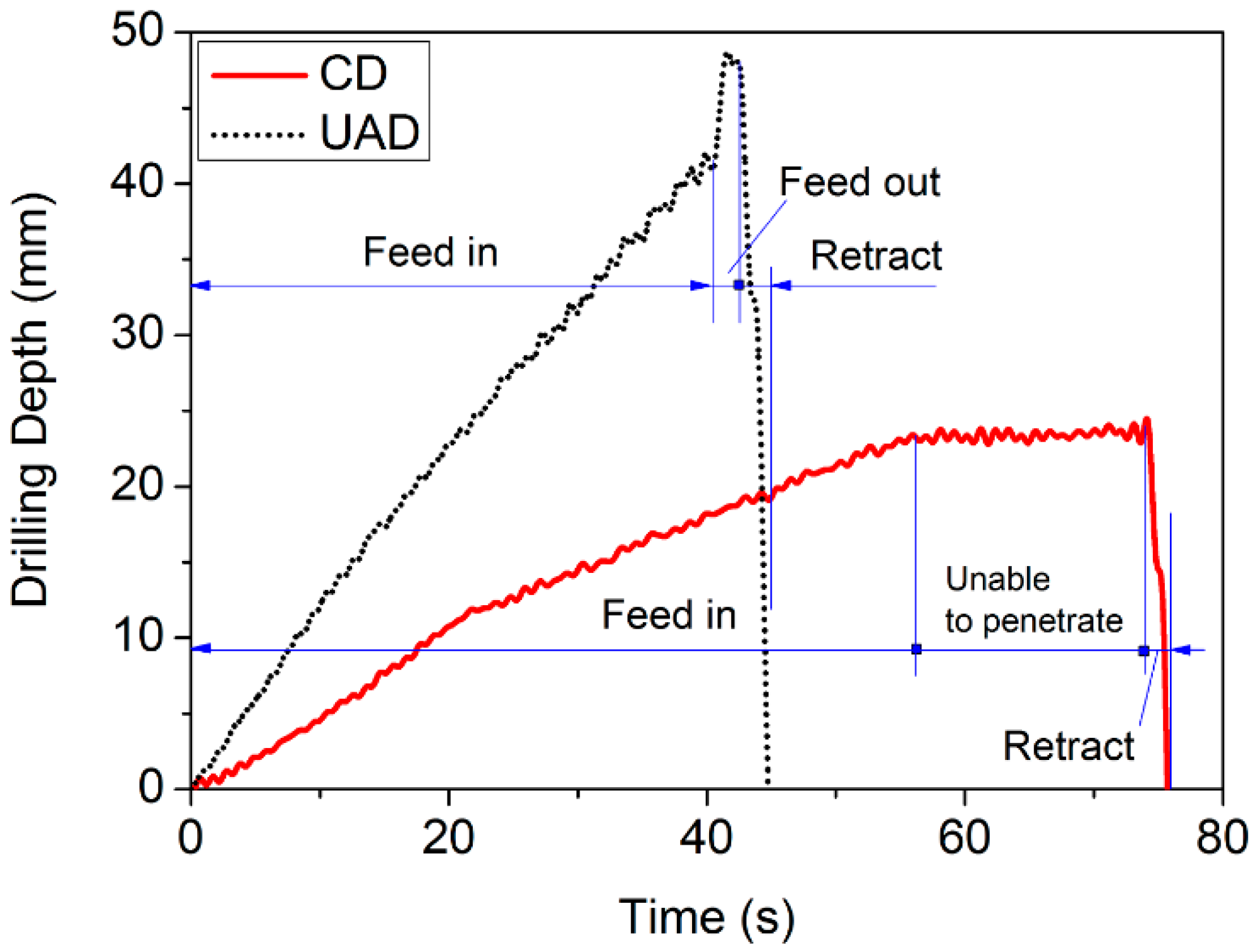
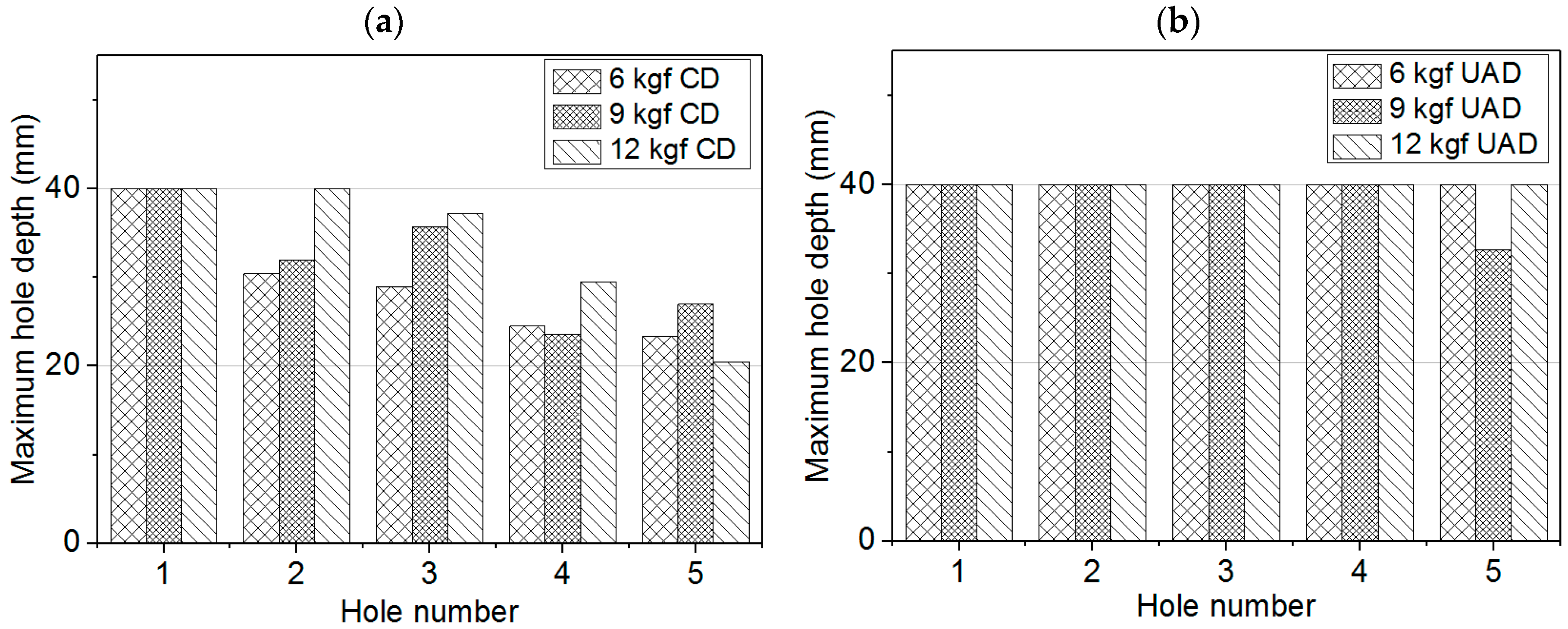
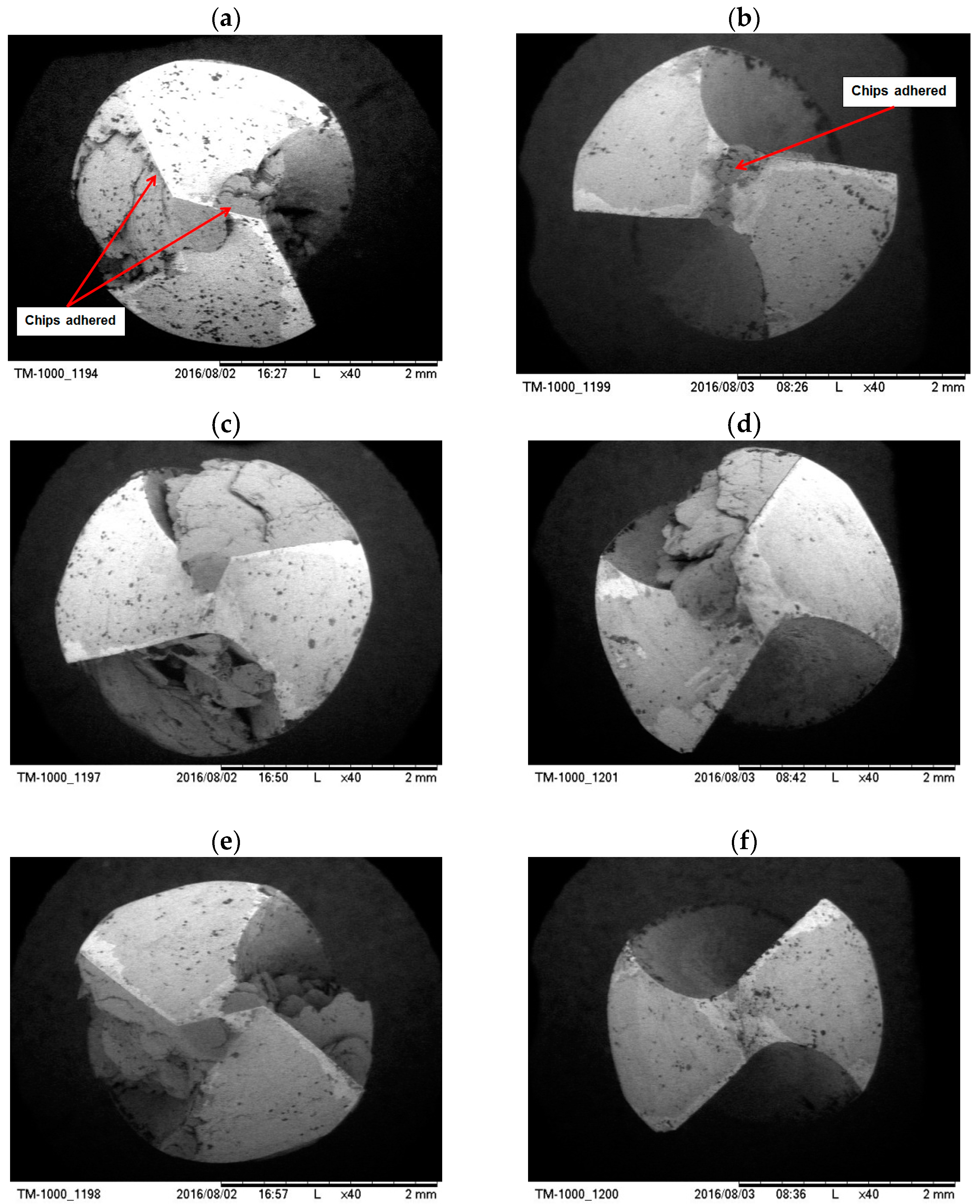
3.1. Machining Ability

In the implemented tests, the obtained hole depth is equal to the displacement of the workpiece and was captured by an LVDT every 0.001 seconds. All experiments were conducted with a programmed hole depth of 40 mm. The readings were noted until a through hole had been produced or when the tool was unable to penetrate the material. Figure 4 presents an example of the time history of the drilling depth obtained when applying an axial force of 6 kgf for both cases of CD and UAD. As shown in Figure 4, the holes were either through drilled (with UAD) or blind (in the case of CD). The time when the tool continuously penetrated the workpiece was named as “Feed in”. If a through hole was successful, a “Feed out” time was taken. If the tool was unable to penetrate for more than 10 seconds, the tool was retracted, and a blind hole was made. For cases of both through and blind holes, a short “Retract” time was then taken for drawing back the workpiece, and the test was finished.
In order to compare the machining abilities of UAD and CD, the maximum values of the hole depths obtained from all 30 tests were taken and are shown in Figure 5.
Figure 5 shows that all holes of number 1 were successful as the tool was totally new. For the remaining holes, all UAD tests completed through holes except for hole number 5 under 9 kgf of axial force. However, only one through hole was made with CD; this was at hole 2 under 12 kgf axial force. In CD, 11 out of 12 holes were blind holes. As observed, the maximum tool life was 5 holes in UAD, as opposed to 1 or 2 holes in CD. It can be seen that UAD prolonged the tool life, as well as improving the machinability.
One reason for this phenomenon could be found by looking at SEM images taken at the cutting edge of tool bits after drilling 5 holes, shown in Figure 6. It can be seen that phenomena of adhesion of chips in flutes appeared in UAD using 9 kgf axial force and in all CD tests. It should be noted that the tool bit used in those cases were unable to cut after a certain time, as mentioned above. As shown in Figure 6, chips in those tests adhered on cutting edges and also flocked in tool flutes, preventing both the cutting process and chip evacuation. This phenomenon did not appear in UAD with 6 kgf or 12 kgf axial force, where all holes were produced successfully. To conclude, the cutting ability of the tool bit quickly dropped because of chip adhesion on the cutter and chip flock in the flutes. Superimposed ultrasonic vibration would be a major cause of the elimination of those phenomena. The two factors found to reflect this effect are torque and temperature, as shown in Section 3.3.

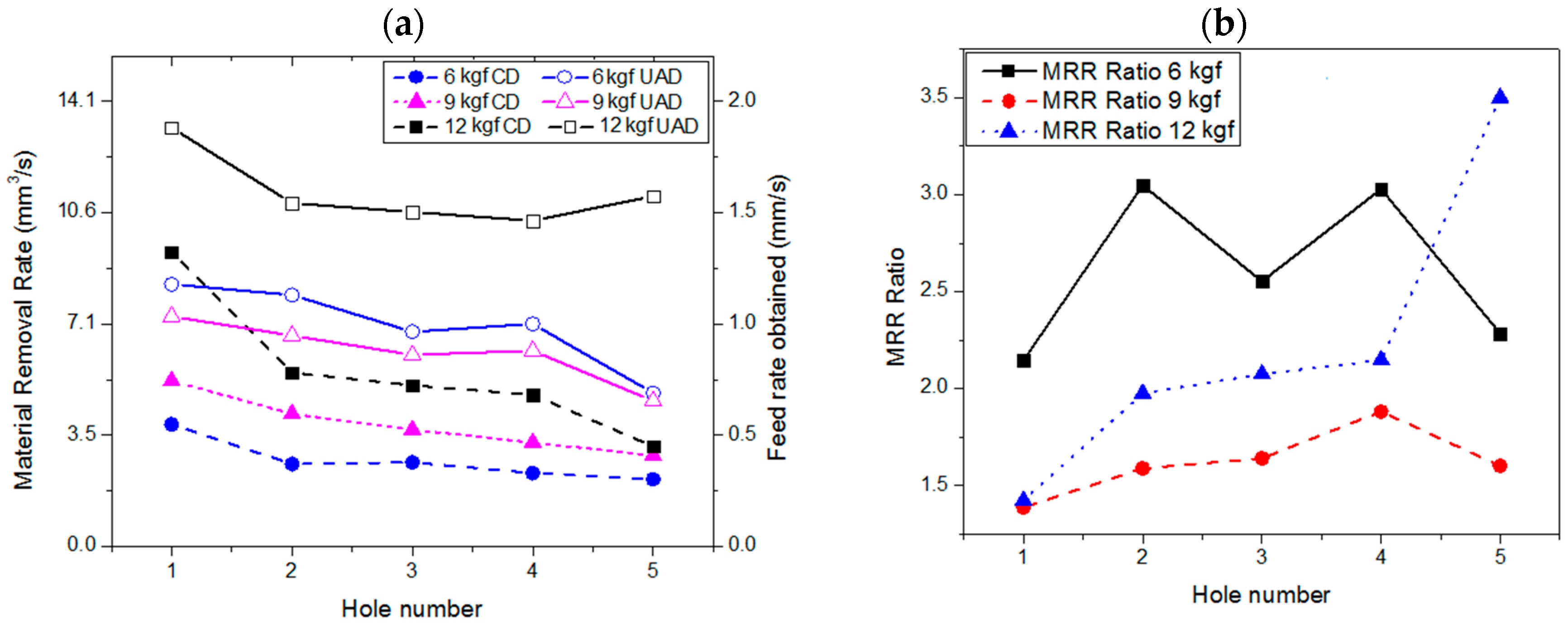
3.2. Material Removal Rate

Denoting the relative displacement of the workpiece with respect to the tool bit as Lk, the material removal rate (MRR) after cutting time Tk can be expressed as follows:
MRR k = π D 2 4 L k T k
where D is the tool diameter.
The average MRR of each test was calculated using Equation (1), where Lk was substituted by the maximum hole depth obtained and Tk was the corresponding time taken. It should be noted that Lk/Tk is actually the feed rate obtained. Ratios between the MRRs of UAD and CD tests at the same axial force and hole number were also found. Figure 7a shows the MRR (values on the left axis) and feed rate (values on the right axis) obtained in all tests. The MRR ratios of UAD compared with those of CD tests are shown in Figure 7b.
As indicated in Figure 7a, at the same level of axial force, the MRR of UAD was significantly higher than that of CD. Under the same drilling conditions, MRRs of later holes were usually smaller than those of the earlier ones as a typical effect of tool wear. It was also noted that the MRR of UAD at 9 kgf axial force was always smaller than that at 6 kgf or 12 kgf axial force. In contrast to CD, higher axial force did not provide a higher MRR and thus there would exist a proper force providing the highest MRR.
In Figure 7b, when applying 12 kgf axial force, the highest MRR ratio of 3.5 appeared at hole 5, meaning that the MRR of UAD was as high as 3.5 times the MRR of CD. In addition, both MRR ratios at 12 kgf and 9 kgf of axial force were all increased for later holes. In these cases, the cutting ability of the tool would decrease faster in CD, causing the MRR in CD to gradually drop down as shown in Figure 7a. However, the MRR ratio in the case of 6 kgf axial force fluctuated in the range of 2.2 to 3, distinctive from that of either 12 kgf or 9 kgf.

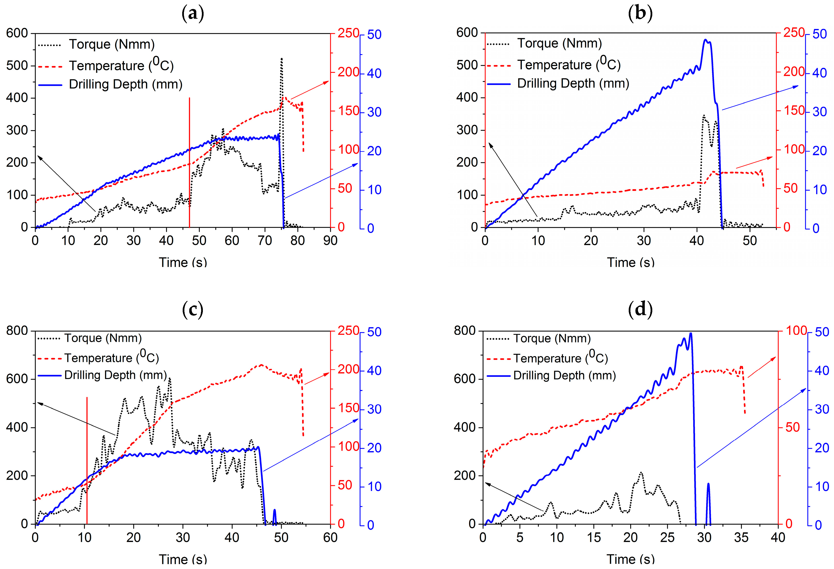
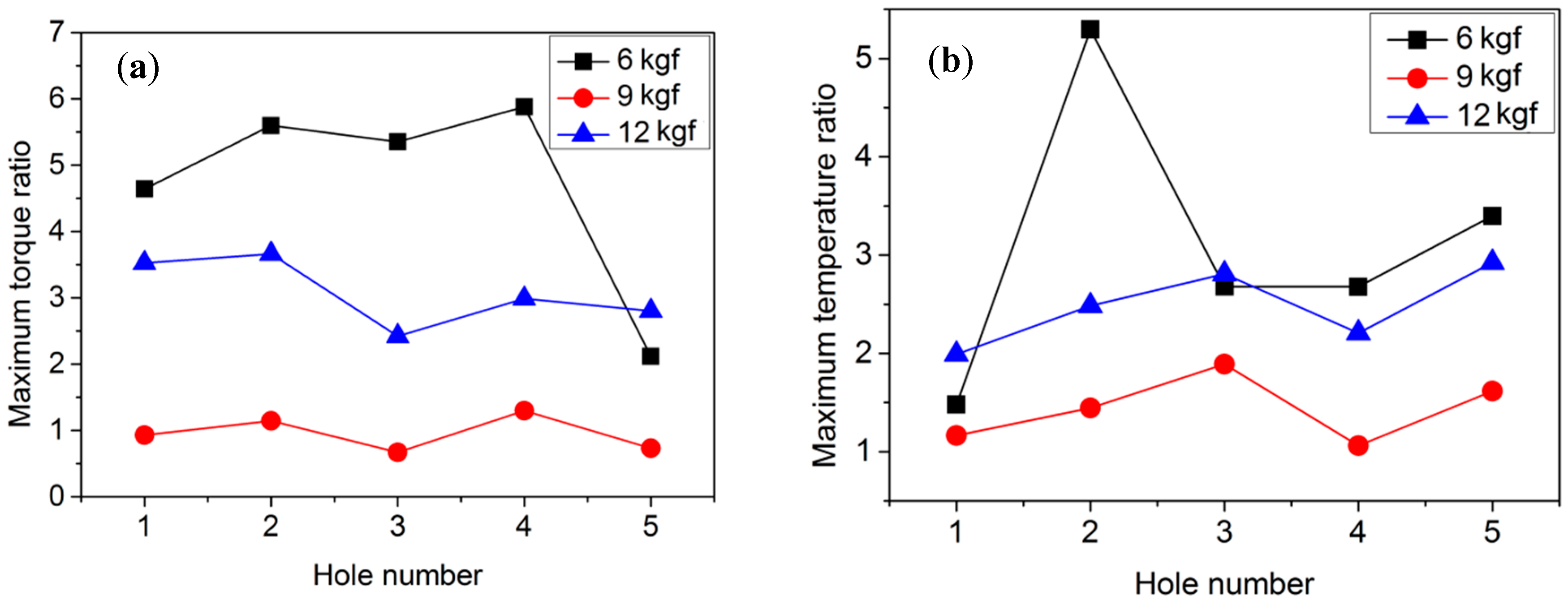
3.3. Torque and Temperature

Four examples of time histories of the torque, workpiece temperature, and the hole depth obtained are demonstrated in Figure 8, where two values of axial force (6 kgf and 12 kgf) were applied.
Figure 8 shows that cutting torque and temperature increased along with the drilling depth. Higher torque and temperature appeared at greater depths of the hole. However, their growth rates in CD were substantially higher than those in UAD.
It is clear that in the cases of CD (Figure 8a,c), just after the torque and then temperature jumped up, the drill bit became unable to penetrate the workpiece. This can be explained by the fact that, at this instant, chips started flocking in the flutes, resulting in increased friction along the hole wall. The drilling chips jammed the flutes, leading to increased pressure of the chips on flutes and hole walls. The increased friction caused a rise in the cutting torque and also caused a temperature increase. At high temperature and pressure, adhesion of the chips onto flute walls occurred, preventing evacuation of chips from the flutes. This could accelerate further chip packing as well as adhesion of the chips onto the cutting edges; thus, the tool would quickly lose its cutting ability, as mentioned in Section 3.1 and shown in Figure 6.
However, the phenomena above were not appeared in both cases of UAD as shown in Figure 8b,d. In these cases, ultrasonic addition would minimize the friction and thus help the chips exit through drill flutes easier; in some UAD tests, chips were in continuous form. This would be one of the most important benefits of UAD and needs to be further investigated.
In order to have a quantity comparison, the maximum values of torque and workpiece temperature during drill progress were taken. Ratios of torque between CD tests and UAD tests at the same hole number were then calculated. Ratios of temperature were found in the same way. Figure 9 presents the torque and temperature ratios with respect to the drilled hole numbers.
Figure 9 shows that almost all values of the investigated ratios were bigger than 1. This means that torque and temperature in CD were higher than those in UAD under the same drilling condition. There were some cases at the axial force of 9 kgf where both torque and temperature ratios were smaller than 1. For the investigated level of axial forces, the force of 9 kgf was the worst case, compared with the levels of 6 kgf and 12 kgf.
As shown in Figure 9a, the torque induced in CD was 2 times (at 6 kgf, hole 5) to 6 times (at 6 kgf, hole 4) higher than that in UAD. Figure 9b indicates that using UAD can reduce the temperature up to 5 times compared with using CD (at hole 2). In addition, the effectiveness of UAD over CD has been found to be increased when drilling a greater number of holes. For example, under the axial force of 6 kgf, the temperature difference at hole 5 is 3.5 times whereas it is only 1.5 times when drilling the first hole. The results indicate the outstanding effectiveness of UAD for reducing torque as well as temperature when compared with CD in deep drilling.

4. Conclusions

This paper implemented an approach to give an insight into the mechanisms providing benefits of UAD over CD. The results of the study are as follows:
Under a certain axial force acting on the workpiece, the tool was unable to cut after the first hole produced with CD, in contrast to five holes with UAD. A direct reason for this was found to be chip adhesion on cutting edges and chip flocking in tool flutes. The material removal rate of UAD was found to be 3.5 times that of CD at an axial force of 12 kgf. It was found that UAD reduced torque up to 5 times and temperature 6 times compared with CD. A rapid positive spike of torque and temperature in CD was observed as a sign of the lost cutting ability of the drill bit. Torque and temperature were low in several UAD tests where chips were in continuous form. Consequently, a proposed mechanism of the major benefits from UAD is the reduction of friction among chips, the hole wall, and tool flutes, causing easier chip evacuation. This would eliminate both adhesion and flocking of the chip inside and thus reduce temperature and torque, leading to elongation of the tool life. Further investigations should be implemented to validate the relationships among friction, chip behavior, torque, and temperature in order to obtain better insight into UAD.

Author Contributions

N.-H.C. and V.-D.N. conceived the original idea, designed and performed experiments. N.-H.C. and T.-V.D. analyzed and interpreted experimental data. N.-H.C. wrote the manuscript with support from V.-D.N. and T.-V.D. All authors provided critical feedback and helped shape the research, analysis and manuscript. V.-D.N. supervised this project.

Funding

This research received no external funding.

Acknowledgments

The authors would like to express their thanks to technical supports and advice from Minh-Duc Tran, Nhu-Khoa Ngo and Tien-Hung Nguyen of Thai Nguyen University of Technology.

Conflicts of Interest

The authors declare no conflict of interest.

References

  1. Amini, S.; Paktinat, H.; Barani, A.; Tehran, A.F. Vibration drilling of Al2024-T6. Mater. Manuf. Processes 2013, 28, 476–480. [Google Scholar] [CrossRef]
  2. Chang, S.S.F.B.; Gary, M. Thrust force model for vibration-assisted drilling of aluminum 6061-T6. Int. J. Mach. Tools Manuf. 2009, 49, 1070–1076. [Google Scholar] [CrossRef]
  3. Chang, S.S.F.B.; Gary, M. Burr size reduction in drilling by ultrasonic assistance. Rob. Comput. Integr. Manuf. 2005, 21, 442–450. [Google Scholar] [CrossRef]
  4. Li, X.F.; Dong, Z.G.; Kang, R.K.; Wang, Y.D.; Liu, J.T.; Zhang, Y. Comparison of Thrust Force in Ultrasonic Assisted Drilling and Conventional Drilling of Aluminum Alloy. Mater. Sci. Forum 2016, 861, 38–43. [Google Scholar] [CrossRef]
  5. Babitsky, V.I.A.; Meadows, V.K.; Meadows, A. Vibration excitation and energy transfer during ultrasonically assisted drilling. J. Sound Vib. 2007, 308, 805–814. [Google Scholar] [CrossRef]
  6. Azarhoushang, B.; Akbari, J. Ultrasonic-assisted drilling of Inconel 738-LC. Int. J. Mach. Tools Manuf. 2007, 47, 1027–1033. [Google Scholar] [CrossRef]
  7. Baghlani, V.; Mehbudi, P.; Akbari, J.; Sohrabi, M. Ultrasonic Assisted Deep Drilling of Inconel 738LC Superalloy. Procedia CIRP 2013, 6, 571–576. [Google Scholar] [CrossRef]
  8. Sanda, A.; Arriola, I.; Navas, V.G.; Bengoetxea, I.; Gonzalo, O. Ultrasonically assisted drilling of carbon fibre reinforced plastics and Ti6Al4V. J. Manuf. Process. 2016, 22, 169–176. [Google Scholar] [CrossRef]
  9. Baghlani, V.; Mehbudi, P.; Akbari, J.; Nezhad, E.Z.; Sarhan, A.A.D.; Hamouda, A.M.S. An optimization technique on ultrasonic and cutting parameters for drilling and deep drilling of nickel-based high-strength Inconel 738LC superalloy with deeper and higher hole quality. Int. J. Adv. Manuf. Technol. 2015, 82, 877–888. [Google Scholar] [CrossRef]
  10. Azghandi, B.V.; Kadivar, M.A.; Razfar, M.R. An Experimental Study on Cutting Forces in Ultrasonic Assisted Drilling. Procedia CIRP 2016, 46, 563–566. [Google Scholar] [CrossRef]
  11. Gupta, A.; Ascroft, H.; Barnes, S. Effect of Chisel Edge in Ultrasonic Assisted Drilling of Carbon Fibre Reinforced Plastics (CFRP). Procedia CIRP 2016, 46, 619–622. [Google Scholar] [CrossRef]
  12. Dahnel, A.N.; Ascroft, H.; Barnes, S. The Effect of Varying Cutting Speeds on Tool Wear during Conventional and Ultrasonic Assisted Drilling (UAD) of Carbon Fibre Composite (CFC) and Titanium Alloy Stacks. Procedia CIRP 2016, 46, 420–423. [Google Scholar] [CrossRef]
  13. Makhdum, F.; Phadnis, V.A.; Roy, A.; Silberschmidt, V.V. Effect of ultrasonically-assisted drilling on carbon-fibre-reinforced plastics. J. Sound Vib. 2014, 333, 5939–5952. [Google Scholar] [CrossRef] [Green Version]
  14. Phadnis, V.A.; Roy, A.; Silberschmidt, V.V. A Finite Element Model of Ultrasonically Assisted Drilling in Carbon/Epoxy Composites. Procedia CIRP 2013, 8, 141–146. [Google Scholar] [CrossRef]
  15. Wang, Y.; Cao, M.; Zhao, X.; Zhu, G.; McClean, C.; Zhao, Y.; Fan, Y. Experimental investigations and finite element simulation of cutting heat in vibrational and conventional drilling of cortical bone. Med. Eng. Phys. 2014, 36, 1408–1415. [Google Scholar] [CrossRef] [PubMed]
  16. Alam, K.; Mitrofanov, A.V.; Silberschmidt, V.V. Experimental investigations of forces and torque in conventional and ultrasonically-assisted drilling of cortical bone. Med. Eng. Phys. 2011, 33, 234–239. [Google Scholar] [CrossRef] [PubMed] [Green Version]
  17. Ke, F.; Ni, J.; Stephenson, D.A. Chip thickening in deep-hole drilling. Int. J. Mach. Tools Manuf. 2006, 46, 1500–1507. [Google Scholar] [CrossRef]
Figure 1. Experimental schema.
Applsci 08 01708 g001
Figure 2. A drawing of the rotary ultrasonic-assisted drilling (UAD).
Applsci 08 01708 g002
Figure 3. Technical schemata (a) in front view and (b) cross-sectional view, and (c) a photograph of the complete experimental fixture setup. (LVDT: linear variable displacement transducer.)
Applsci 08 01708 g003
Figure 4. Time histories of the hole depth obtained with conventional drilling (CD) (red solid line) and UAD (black dot) when an axial force of 6 kgf was applied.
Applsci 08 01708 g004
Figure 5. Maximum hole depth of all tests using (a) CD and (b) UAD.
Applsci 08 01708 g005
Figure 6. Photographs taken at cutter edges after producing 5 holes in CD (a,c,e) and UAD (b,d,f); an axial force of 6 kgf (a,b), 9 kgf (c,d), or 12 kgf (e,f) was applied.
Applsci 08 01708 g006
Figure 7. (a) Material removal rate (MRR) and (b) MRR ratios at different axial force levels. A higher ratio means a higher MRR of UAD compared with that of CD.
Applsci 08 01708 g007
Figure 8. Time histories of cutting torque, temperature, and drilling depth with respect to time in CD (a,c) and UAD (b,d) with conditions of axial force of 6 kgf, hole 4 (a,b) and 12 kgf, hole 5 (c,d).
Applsci 08 01708 g008
Figure 9. Maximum torque ratio (a) and maximum temperature ratio (b) with respect to hole number. Higher ratio means higher torque or temperature in CD compared with that in UAD.
Applsci 08 01708 g009
Table 1. The parameters for experimental tests.
Spindle speed1500 rpm
Axial force6, 9, 12 kgf
Cutting conditionDry
Drill diameter3 mm
Hole depthThrough, 40 mm

