Review

Laser-Control of Ultrafast π-Electron Ring Currents in Aromatic Molecules: Roles of Molecular Symmetry and Light Polarization

1
Department of Chemistry, Graduate School of Science, Tohoku University, Sendai 980-8578, Japan
2
Department of Applied Chemistry, Institute of Molecular Science, and Center for Interdisciplinary Molecular Science, National Chiao-Tung University, Hsin-Chu 300, Taiwan
*
Author to whom correspondence should be addressed.
Submission received: 30 October 2018 / Accepted: 19 November 2018 / Published: 22 November 2018
(This article belongs to the Special Issue Attosecond Science and Technology: Principles and Applications)

Abstract

:
Being motivated by the recent progress in attosecond laser technology, we theoretically explore the strategy of inducing ultrafast electron dynamics inherent to aromatic molecules, i.e., ring currents by means of polarized laser pulses. The main topic of discussion is how to control the direction of ring currents in an aromatic molecule of low symmetry, for which the design of an efficient control pulse cannot be achieved intuitively. We first consider a system with a single aromatic ring and show that coherent π-electron angular momentum, which oscillates with time, can be produced and controlled by a polarized laser pulse with its ellipticity and orientation properly chosen. Nonadiabatic couplings with molecular vibration gradually weaken the angular momentum, while the vibrational amplitude strongly depends on the polarization of incident light. This suggests the conversion of the polarization dependence of ring current into that of subsequent vibration, which may open a way to detect laser-driven ultrafast electron dynamics by vibrational spectroscopy. The laser-control scheme for the ring current is then extended to a molecule with two aromatic rings, which exhibits characteristic phenomena absent in that with a single ring. We demonstrate that two-dimensional switching of the direction of angular momentum is possible in such molecules. In addition, ring current can be localized at a specific ring by tailored lasers. The application of the present control method to polycyclic aromatic hydrocarbons will lead to the development of next-generation organic optical switching devices.

1. Introduction

Chemical reaction (i.e., chemical bond formation and cleavage) can be viewed as a drastic change in nuclear positions, accompanied by electron transfer or migration between atoms in matter. In photochemical reactions, nuclear motion is initiated by the generation of a coherent superposition of vibrational eigenstates, i.e., a quantum vibrational wave packet (WP) with light. In general, the energy spacing between vibrational eigenstates is in the infrared (IR) region. Hence, nuclei pass through a transition state of photochemical reactions within tens or hundreds of femtoseconds and the process of the passage can be directly measured by means of femtosecond laser pulses [1]. Continuous progress in laser technology has been promoting this research field called femtosecond chemistry or femtochemistry [2,3,4,5], which aims at real-time observation of chemical reactions, since the 1980s.
Currently, attosecond pulse generation [6,7,8,9,10,11,12,13,14], which was achieved in the early 2000s, is opening a door to unexplored possibilities of chemistry and physics. Attosecond light pulses have been expected to be a powerful tool not only to observe but also to drive electron motion in molecules, which is much faster than nuclear motion and thus steers chemical reactions [15,16]. In analogy to nuclear dynamics, the fundamental mechanism of laser-induced ultrafast electron dynamics is to create a coherent superposition of electronic eigenstates, i.e., an electronic WP. The bandwidth as well as the central frequency of an attosecond laser pulse produced by high harmonic generation [17,18,19,20,21,22] lies in the extreme ultraviolet (XUV) region, which enables simultaneous transitions from the electronic ground state to many excited states. The electronic wave function of the superposition state varies in time periodically according to the energy gaps between the eigenstates involved, giving rise to large-scale electron motion in molecules. The period of the electronic state change is only a few femtoseconds for visible-light energy gaps or even of an attosecond order for UV energy gaps, where nuclei are almost static. The instantaneous and dramatic change in molecular electronic states caused by attosecond laser irradiation may lead to the control of molecular functionalities and chemical reactions, which is one of the ultimate goals of chemistry. The development of the new discipline “attosecond chemistry” will bring innovation to various areas, such as materials science and nanotechnology.
In line with this direction, a number of theoretical researches have been carried out on laser-induced ultrafast electron dynamics in molecules [23,24,25,26,27,28,29,30,31,32,33,34,35,36,37]. For diatomic and triatomic systems, quantum simulations of electron localization in lithium hydride LiH [25,26,27] and lithium cyanide LiCN [23] were performed. Electron localization in such linear molecules can be regarded as a switching of electric dipole moments. A similar localization phenomenon was also predicted for benzene [34,35,36,37], which is a larger, aromatic molecule. Gathering delocalized π electrons to specific atoms or bonds in an aromatic ring results in the weakening of aromaticity. In addition to these works dealing with electronic WPs of neutral molecules, investigations have also been conducted on electron (or charge) dynamics in cations [38,39,40,41,42,43,44,45,46,47]. The hole density evolutions initiated upon the sudden removal of an electron from N-methylacetamide [41] glycine [43,45], and small peptides [44] by attosecond laser pulses were calculated. The hole migrates from one end of the molecules to the other on attosecond to few-femtosecond time scales in line with the above expectation of the electronic state change for visible-light or UV energy gaps.
The theoretical proposal for ultrafast charge migration was put into practice in 2014 for phenylalanine by pump-probe spectroscopy [48]. A sub-300-as XUV pump pulse triggers ionization and subsequent charge migration; a 4-fs visible/near-IR probe pulse then generates an immonium dication fragment whose yield exhibits a 4-fs oscillation as a sign of the charge migration. To the best of our knowledge, this is the first experimental application of attosecond laser pulses to charge migration in molecules. Shortly thereafter, control of charge migration was demonstrated for pre-oriented iodoacetylene HCCI by using intense near-IR pulses (instead of attosecond XUV pulses) [49,50]. The linear polarization direction chosen perpendicular or parallel to its molecular axis affects the superposition of cationic ground and excited states created by multiphoton ionization and thus governs the fate of hole propagation. This experiment tells us that laser control of ultrafast electron dynamics in molecular systems is becoming reality.
There are two key factors to attain a desired linear combination of electronic eigenstates: molecular symmetry and light polarization. This can be readily understood from the fact that the probability of an optical transition between two states is dominated by the inner product of the corresponding transition dipole moment, whose direction depends on molecular symmetry, and the electric field vector of incident light. For instance, it is impossible to populate an excited state whose transition moment from the ground state is perpendicular (orthogonal) to the polarization vector. Manipulating the populations of eigenstates that participate in the superposition state is not enough; the relative quantum phase between the eigenstates is crucial, that is, coherent control is required. The initial value of the relative quantum phase can in principle be tuned by laser polarization for a spatially oriented molecule and then it evolves periodically until the molecule starts to vibrate. The initial relative phase thereby dictates electron motion inside a molecule, e.g., the timing of electron localization. The choice of polarization is relatively easier and often made intuitively for highly symmetric molecules such as linear ones; the experiment of charge migration in HCCI+ is a typical example (although the control was not fully coherent) [49,50]. However, many systems of interest (e.g., complex organic or biologically relevant molecules) have low or no symmetry. The strategy of designing a polarized laser pulse to control electron dynamics in such molecules is unclear and needs to be established.
In the present review article, we focus on the circulation of π electrons along an aromatic ring, i.e., the so-called ring current. This phenomenon, where π electrons travel in either a clockwise or anticlockwise direction around the ring, is a model case to study the manipulation of directional electron motion in complex molecules. Numerical simulations showed that much stronger ring currents can be produced in benzene [51] and Mg porphyrin [52,53,54] by a circularly polarized laser pulse than by a static magnetic field available with present technology. For these molecules the direction of electron flow is determined by the helicity of circular polarization. The mechanism of laser-driven ring currents in the highly symmetric aromatic molecules (D6h for benzene and D4h for Mg porphyrin) is unambiguous as will be briefly described in Section 2.1. How can ring currents be induced and controlled in aromatic molecules of lower symmetry by polarized light?
The rest of this article offers a solid answer to the above question obtained in a series of our theoretical efforts. In Section 2, our quantum WP simulations reveal the laser-polarization effects on nonadiabatically coupled ring current and molecular vibration. We first propose a general pulse design scheme for ring currents in molecules with a single aromatic ring, which is applicable to systems of both high and low symmetry. Numerical examples are presented to illustrate the characteristic behavior of controlled ring currents in 2,5-dichloropyrazine (C2h), which is a lower-symmetry derivative of heterocyclic pyrazine (D2h). Nonadiabatic coupling between ring current and molecular vibration is significant when the current lasts as long as vibrational periods (tens of femtoseconds); however, the coupling was completely ignored in the previous studies [51,52,53,54] based on the frozen-nuclei approximation. In Section 3, the pulse design scheme is extended to molecules with plural (in particular, two) aromatic rings. The extended theory is applied to (P)-2,2′-biphenol (C2), which is a nonplanar system with axial chirality. We demonstrate electron dynamics inherent to multi-ring molecules, i.e., localization of ring current at a specific ring. Finally, Section 4 concludes the article.

2. Laser Control of Ring Currents in a Molecule Having a Single Aromatic Ring

In this section, we present the results of theoretical analyses and numerical calculations on laser-driven ring currents in a molecule with a single aromatic ring as the simplest system. To quantify the strength and direction of ring currents, the concept of electronic angular momentum eigenstates is essential since in general angular momentum serves as a measure of circular motions of a particle. We begin this section by proposing the basic idea to generate ring currents by polarized lasers from a viewpoint of the relationship between molecular symmetry and angular momentum eigenstates.

2.1. Basic Idea of Laser-Driven Ring Currents: Molecular Symmetry and Angular Momentum Eigenstates

First of all, we briefly summarize the mechanism of ring currents in benzene excited by a circularly polarized laser pulse [51] as an example. Benzene belongs to the D6h point group at its equilibrium geometry and its C6 axis is chosen as the z axis. Its highest occupied and lowest unoccupied molecular orbitals (HOMO and LUMO) are e1g and e2u orbitals, respectively. As for multielectron states constructed from MOs, there exist doubly degenerate 1E1u excited states whose major components are the HOMO-LUMO excitations. By approximating the hexagonal structure of benzene with a complete cylindrical ring, its symmetry becomes D∞h and the z component of electronic angular momentum is quantized in units of the Dirac constant ħ. The doubly degenerate 1E1u excited states can be regarded as the eigenstates of the angular momentum operator l ^ z with the quantum number m = ±1. [55,56,57,58] We denote the 1E1u states with m = +1 and −1 by | 1 E 1 u + 1 and | 1 E 1 u 1 , respectively. The angular momentum eigenstates | 1 E 1 u ± 1 have a complex wave function that can be expressed as a linear combination of two real ones | 1 E 1 u x 1 and | 1 E 1 u y 1 :
| 1 E 1 u ± 1 = 2 1 / 2 ( | 1 E 1 u x 1 ± i | 1 E 1 u y 1 ) .
Recalling that complex atomic orbitals (AOs) | 2 p + 1 and | 2 p 1 are angular momentum eigenstates of an electron in a hydrogen atom, the relation in Equation (1) is similar to that between the complex AOs and real ones | 2 p x and | 2 p y . The transition moments 1 A 1 g 1 | μ ^ | 1 E 1 u x 1 and 1 A 1 g 1 | μ ^ | 1 E 1 u y 1 , where | 1 A 1 g 1 is the ground state and μ ^ is the electric dipole moment operator, have the same magnitude and are perpendicular to each other in the xy plane. The x and y axes can thus be taken parallel to 1 A 1 g 1 | μ ^ | 1 E 1 u x 1 and 1 A 1 g 1 | μ ^ | 1 E 1 u y 1 , respectively. When a circularly polarized laser pulse propagates along the z axis, the spin angular momentum of a photon selects either | 1 E 1 u + 1 or | 1 E 1 u 1 and accordingly π electrons travel clockwise or anticlockwise around a ring depending on the sign of m. This is the origin of the unique correspondence between the direction of ring currents and the helicity of circular polarization. One can immediately find it impossible to rotate π electrons in benzene by a linearly polarized laser pulse, which has no spin angular momentum.
We next assume that the symmetry of benzene is lowered, e.g., by introducing functional groups and/or replacing some carbon atoms in its ring with heteroatoms. The degeneracy between | 1 E 1 u + 1 and | 1 E 1 u 1 ( | 1 E 1 u x 1 and | 1 E 1 u y 1 ) is then broken and they split into a pair of quasi-degenerate states. We denote the real wave functions of the states closer to | 1 E 1 u x 1 and | 1 E 1 u y 1 by | X and | Y , respectively. Even though there exists no excited state that is an exact eigenstate of l ^ z in such a system, sufficiently short laser pulses can prepare a coherent superposition of the optically allowed quasi-degenerate states as mentioned in Section 1. The approximate angular momentum eigenstates can be defined in analogy to Equation (1) as follows:
| ± 2 1 / 2 ( | X ± i | Y ) ,
where the matrix elements ± | l ^ z | ± are close to ±ħ. After a laser pulse prepares either | + or | , it subsequently evolves in time as a coherent nonstationary state because of the nonzero energy gap between | X and | Y :
e i H ^ 0 t / ħ | ± = 2 1 / 2 ( e i ω X t | X ± i e i ω Y t | Y ) = e i ω X t 2 1 / 2 ( | X ± i e i 2 Δ ω t | Y ) ,
where H ^ 0 is the field-free electronic Hamiltonian, ωX (ωY) is the angular frequency of | X ( | Y ), and 2∆ωωYωX. Note that ∆ω is positive (negative) when | X is lower (higher) in energy than | Y . The approximate angular momentum eigenstates can be transiently created within the period of the electronic state change T ≡ π/|∆ω|. This means that transient ring currents can be achieved by selective generation of an approximate angular momentum eigenstate. In Section 2.2, we will propose the strategy for generating predominantly either | + or | by a polarized laser field.

2.2. Laser-Polarization Effects on Ring Currents within the Frozen-Nuclei Approximation

We analyze the effects of light polarization on an optical excitation of a molecule with a single aromatic ring using a three-level model of the ground state and two excited states. Here, the frozen-nuclei approximation, which ignores all nuclear degrees of freedom, is adopted. We analytically and numerically show that the coherent superposition of the quasi-degenerate states and the resultant angular momentum can be controlled by the ellipticity and orientation of the polarization ellipse of an incident laser.

2.2.1. General Form of Polarized Laser Pulses

Before entering into the analysis of optical excitation processes in aromatic molecules, let us describe the mathematical form of a classical laser field of arbitrary polarization. It is given in the dipole approximation by:
E ( t ) = E 0 2 f ( t ) [ e i ( ω t + φ ) e + e i ( ω t + φ ) e * ] ,
where t is time, E0 is the peak field strength, ω is the central frequency, φ is the optical phase, and e is the complex polarization unit vector. The envelope function f(t) varies between zero and unity for [0, tf] with tf being the pulse duration; otherwise f(t) = 0. The polarization vector e for an arbitrarily polarized light is:
e = e i δ ( cos β ) e + 1 + e i δ ( sin β ) e 1 ,
where e+1 and e−1 are the spherical unit vectors corresponding to positive and negative helicities (spins), respectively. When the laser field propagates in the z direction and thus oscillates in the xy plane, the spherical unit vectors can be defined as follows:
e ± 1 2 1 / 2 ( e x ± i e y ) ,
where ex and ey are the unit vectors in the x and y directions, respectively (in some references the signs are placed before 2−1/2). Following the convention in optics, we refer to e+1 and e−1 as left and right circular polarizations, respectively. In Equation (5), δ denotes the orientation angle of the major axis of the polarization ellipse with respect to the x axis and β is termed the ellipticity angle in this article (Figure 1). The range of β is [0, π/2] and the minor-to-major axial ratio of the polarization ellipse is |tan (π/4 − β)|; for example, β = 0, π/4, and π/2 designate left circular, linear, and right circular polarizations, respectively. The general form of E(t) in Equation (4) will be utilized in the model analysis presented in Section 2.2.2.

2.2.2. Three-Level Model Analysis of Optical Excitation

We formulate the polarization effects on the optical excitation in aromatic molecules of low symmetry. The time-dependent Schrödinger equation for a molecule in a laser field E(t) is given in the length gauge by:
i ħ t | Ψ ( t ) = [ H ^ 0 μ ^ E ( t ) ] | Ψ ( t ) .
The system is initially in its ground state | G . We assume that only the ground and quasi-degenerate excited states are involved in the excitation process. The energy of | G is defined to be zero and the central frequency ω of the laser field is set on resonance with the average energy of | X and | Y : ω = ωX + ∆ω = ωY − ∆ω. The state vector | Ψ ( t ) is then expanded as:
| Ψ ( t ) = c G ( t ) | G + c X ( t ) e i ( ω Δ ω ) t | X + c Y ( t ) e i ( ω + Δ ω ) t | Y .
All diagonal elements of μ ^ are assumed to be zero for simplicity, although this assumption is not necessary for our model analysis to be valid. For off-diagonal elements, we denote µn G | μ ^ | n = n | μ ^ | G ≠ 0 (n = X and Y), while X | μ ^ | Y = Y | μ ^ | X = 0 . As defined in Section 2.1, the z axis is perpendicular to the ring plane, which coincides with the xy plane. Because the excitations to | X and | Y correspond to ππ* transitions, both µX and µY lie in the xy plane. Substituting Equations (4) and (8) into Equation (7) yields the equation of motion for the expansion coefficient vector C(t) ≡ ( c G ( t ) , c X ( t ) , c Y ( t ) ) T :
d C ( t ) d t = i ( 0 g X ( t ) g Y ( t ) g X ( t ) * 0 0 g Y ( t ) * 0 0 ) C ( t ) ,
where
g X ( t ) = f ( t ) 2 { Ω X e i [ ( 2 ω Δ ω ) t + φ ] + Ω X * e i ( Δ ω t + φ ) } ,
g Y ( t ) = f ( t ) 2 { Ω Y e i [ ( 2 ω + Δ ω ) t + φ ] + Ω Y * e i ( Δ ω t φ ) } ,
and Ω n ( E 0 / ħ ) μ n e (n = X and Y) are the complex Rabi frequencies. The initial condition is C ( 0 ) = ( 1 , 0 , 0 ) T . To simplify Equation (10a,b), we apply the rotating-wave approximation (RWA) [59]: Near resonance (i.e., ω >> |∆ω|) is assumed so that the contribution of the first terms in Equation (10a,b), which are rapidly oscillating exponentials, to the time evolution of C(t) is averaged out and removed. Under the RWA, Equation (9) is transformed into:
d C ( t ) d t = i f ( t ) 2 ( 0 Ω X * e i ( Δ ω t + φ ) Ω Y * e i ( Δ ω t φ ) Ω X e i ( Δ ω t + φ ) 0 0 Ω Y e i ( Δ ω t φ ) 0 0 ) C ( t ) .
In order to efficiently prepare an approximate angular momentum eigenstate | + or | defined in Equation (2), the quasi-degenerate states | X and | Y should be populated equally. The laser field is therefore assumed to satisfy | Ω X | = | Ω Y | or, at least, | Ω X | | Ω Y | . This requires
e i 2 δ tan β = ( e i θ μ X μ Y ) e + 1 ( e i θ μ X μ Y ) e 1 ,
where θ is the relative phase between ΩX and ΩY, that is, θ ≡ arg(ΩYX). The condition | Ω X | = | Ω Y | can be fulfilled with the ellipticity angle β and orientation angle δ determined by the absolute value and argument of the right-hand side of Equation (12), respectively. To render Equation (11) more compact, we introduce an alternative pair of superposition states:
| U ± 1 Ω ¯ ( Ω X | X ± Ω Y | Y ) = Ω X Ω ¯ ( | X ± e i θ | Y ) ,
where Ω ¯ ( | Ω X | 2 + | Ω Y | 2 ) 1 / 2 = 2 1 / 2 | Ω X | = 2 1 / 2 | Ω Y | . One can easily find that they are normalized and orthogonal to each other. We rewrite Equation (8) in terms of these superposition states as:
| Ψ ( t ) = c G ( t ) | G + e i ( ω t + φ ) [ c + ( t ) | U + + c ( t ) | U ] ,
where
c ± ( t ) 1 Ω ¯ [ Ω X * e i ( Δ ω t + φ ) c X ( t ) ± Ω Y * e i ( Δ ω t φ ) c Y ( t ) ] .
Then, the time evolution of the new coefficient vector D ( t ) ( c G ( t ) , c + ( t ) , c ( t ) ) T follows:
d D ( t ) d t = i 2 ( 0 Ω ¯ f ( t ) 0 Ω ¯ f ( t ) 0 2 Δ ω 0 2 Δ ω 0 ) D ( t )
with the initial condition D ( 0 ) = ( 1 , 0 , 0 ) T .

2.2.3. Case of Degenerate Excited States

Before proceeding to the solution of Equation (16) for a quasi-degenerate system, let us consider the degenerate case of ∆ω = 0 for highly symmetric aromatic molecules such as benzene and Mg porphyrin. In this case, Equation (16) becomes simple, namely:
d D ( t ) d t = i Ω ¯ 2 f ( t ) ( 0 1 0 1 0 0 0 0 0 ) D ( t ) .
The system practically consists of the two states | G and | U + . It is easy to integrate Equation (17):
D ( t ) = ( cos [ Ω ¯ 2 F ( t ) ] i sin [ Ω ¯ 2 F ( t ) ] 0 ) ,
where F ( t ) 0 t d t f ( t ) . This indicates that the so-called π pulse [59], which satisfies Ω ¯ F ( t f ) = π , achieves complete population inversion from | G to | U + . Inserting Equation (18) into Equation (14) yields the following:
| Ψ ( t ) = cos [ Ω ¯ 2 F ( t ) ] | G + i Ω X Ω ¯ sin [ Ω ¯ 2 F ( t ) ] e i ( ω t + φ ) ( | X + e i θ | Y ) .
The relative quantum phase between | X and | Y coincides with that between the Rabi frequencies ΩX and ΩY, i.e., θ, which is independent of time and controllable by the ellipticity angle β and orientation angle δ. A desired superposition of the degenerate states can be created by tuning the polarization of incident light properly. The populations of | + and | , which are the exact eigenstates of l ^ z in this case, are given by:
P ± ( t ) | ± | Ψ ( t ) | 2 = 1 2 sin 2 [ Ω ¯ 2 F ( t ) ] ( 1 ± sin θ )
and the expectation value of l ^ z is:
l z ( t ) Ψ ( t ) | l ^ z | Ψ ( t ) = ħ sin 2 [ Ω ¯ 2 F ( t ) ] sin θ .
The sign of lz(t) (in other words, the direction of ring currents) depends on the relative quantum phase θ and remains unchanged throughout the time evolution: Ring current flows in a sole direction even after a laser pulse vanishes at t = tf.
We revert to Equation (12), which connects the relative quantum phase θ to the ellipticity angle β and orientation angle δ. As stated for benzene, where | G = | 1 A 1 g 1 , | X = | E 1 u x 1 , and | Y = | E 1 u y 1 , in Section 2.1, µX and µY of highly symmetric aromatic molecules have the same magnitude and are perpendicular to each other: ||µX|| = ||µY|| and µXµY = 0. The x and y axes can thus be chosen to be parallel to µX and µY, respectively. As a result, Equation (12) is reduced to:
e i 2 δ tan β = e i θ i e i θ + i = e i π / 2 tan [ 1 2 ( π 2 θ ) ] ,
which involves neither transition moments nor spherical unit vectors and is purely imaginary. Given a value of β, there exist two solutions of Equation (22):
δ = ± π 4   and   θ = π 2 2 β .
The major axis of the polarization ellipse with δ = π/4 bisects the angle between µX and µY; that with δ = − π/4 is perpendicular to it. In both cases, the value of lz(tf) for the π-pulse excitation is ħsinθ = ħcos2β.
We present illustrative examples and the case of linear polarization (β = π/4) is the first one; Equation (5) is then rewritten as:
e = ( cos δ ) e x + ( sin δ ) e y
and δ determines the polarization direction. The Rabi frequencies ΩX and ΩY are thus real-valued and their relative phase θ takes either zero or π. Henceforth, we denote the linear polarization vectors for θ = 0 (e = +1) and π (e = −1) by e(+) and e(−), respectively. Do not confuse them with the spherical unit vectors e+1 and e−1. The values of δ for e(+) and e(−) are π/4 and −π/4, respectively, from Equation (23). As in Equation (19), a linearly polarized laser pulse with e(+) [e(−)] creates an in-phase (out-of-phase) superposition | X + | Y ( | X | Y ), which is an equal mixture of | + and | : P+(t) = P(t) and thus lz(t) = 0 for all t. It is impossible to trigger ring currents in a degenerate system by a linearly polarized laser pulse.
Next, for circular polarization, β = 0 (π/2) provides e = ee+1 (ee−1) and δ acts as an additional optical phase, which can be set to any value since Equation (19) tells us that the optical phase does not influence the superposition of the degenerate states. From the definition of θ as an argument of ΩYX, we obtain θ = ± (ηYηX) for e±1, where ηX (ηY) is the angle of µX (µY) with respect to the x axis; θ = ±π/2 (e = ±i) in a degenerate system. The superposition states | U ± are therefore identical to the exact angular momentum eigenstates | ± ( | ) for left (right) circular polarization, while optical excitation occurs only to | U + . Ring current flows in the direction inherent to the eigenstate generated as noted in Section 2.1.
The phase factor e yielded by elliptical polarization is neither real nor purely imaginary regardless of whether δ = π/4 or −π/4. The resultant behavior of π electrons is intermediate between those for linear and circular polarizations: The direction of ring currents is determined by the more populated of | + or | , while the magnitude of lz(tf) is less than ħ even for the π-pulse excitation.

2.2.4. Case of Quasi-Degenerate Excited States

Now, we move on to the quasi-degenerate case of Δω 0 for aromatic molecules of low symmetry. It is difficult to analytically integrate Equation (16) with an arbitrary envelope function f(t). For this reason, f(t) is restricted to a rectangular function: f(t) = 1 for [0, tf] and otherwise zero. During irradiation we have:
d D ( t ) d t = i 2 ( 0 Ω ¯ 0 Ω ¯ 0 2 Δ ω 0 2 Δ ω 0 ) D ( t )
and its solution is derived as:
D ( t ) = ( ( Ω ¯ Ω ) 2 cos ( Ω 2 t ) + ( 2 Δ ω Ω ) 2 i Ω ¯ Ω sin ( Ω 2 t ) Ω ¯ ( 2 Δ ω ) Ω 2 [ 1 cos ( Ω 2 t ) ] ) .
The generalized Rabi frequency Ω [ Ω ¯ 2 + ( 2 Δ ω ) 2 ] 1 / 2 is the root mean square of the Rabi frequencies and the detuning frequency 2∆ω. The pulse area of a laser field for a quasi-degenerate system is defined as ΩF(tf), which is equal to Ωtf in the rectangular-envelope case. The ground state | G can be fully emptied by a rectangular-envelope pulse that meets 2 | Δ ω | Ω ¯ and has a pulse area of 2 arccos [ ( 2 Δ ω / Ω ¯ ) 2 ] . The pulse area of this laser field (termed the full-excitation pulse in this article) is larger than that of the π pulse, that is, 2 arccos [ ( 2 Δ ω / Ω ¯ ) 2 ] > π (but not larger than 2π); however, in fact, the full-excitation pulse is very close to the π pulse for Δω 0. The electronic WP of a quasi-degenerate system is eventually written down as:
| Ψ ( t ) = [ ( Ω ¯ Ω ) 2 cos ( Ω 2 t ) + ( 2 Δ ω Ω ) 2 ] | G + i Ω X Ω α ( t ) e i ( ω t + φ ) { | X + e i [ θ ϑ ( t ) ] | Y } ,
where
α ( t ) 2 sin ( Ω 4 t ) [ cos ( Ω 4 t ) + i 2 Δ ω Ω sin ( Ω 4 t ) ] = 2 sin ( Ω 4 t ) α ¯ ( t )
and ϑ ( t ) 2 arg α ¯ ( t ) . The relative quantum phase between | X and | Y is θϑ(t) and its temporal behavior is the main subject of discussion in Section 2.2. The populations P±(t) are derived as:
P ± ( t ) = 1 2 [ Ω ¯ Ω | α ( t ) | ] 2 { 1 ± sin [ θ ϑ ( t ) ] }
and the angular-momentum expectation value lz(t) is
l z ( t ) = λ [ Ω ¯ Ω | α ( t ) | ] 2 sin [ θ ϑ ( t ) ] ,
where λ + | l ^ z | + = | l ^ z | (> 0). In sharp contrast to Equation (21), the time-dependent phase ϑ(t) may change the direction of ring currents during irradiation.
For aromatic molecules of low symmetry, where ||µX|| ≠ ||µY|| and µXµY ≠ 0 in general, Equations (22) and (23) do not strictly hold. In this case, the linear polarization vectors e(+) (θ = 0) and e(−) (θ = π) are determined by [55,57,60,61,62]:
± μ X e ( ± ) = μ Y e ( ± ) ,
which fulfills ± Ω X = Ω Y . Once µX and µY are given, the values of δ for e(+) and e(−) can be readily evaluated from Equation (31). It is straightforward to find a pair of β and δ for the other values of θ from Equation (12). Circular polarizations do not exactly satisfy Equation (12) unless the magnitudes of µX and µY happen to be equal. If Δω 0, the relationship among β, δ, and θ should be close to that for degenerate systems; for example, e(+) and e(−) should be almost perpendicular to each other, and we approximately have ±iΩX ΩY (θ ± π/2) for e±1.
The time-dependent part of the relative quantum phase, i.e., ϑ(t) obeys the following from its definition:
tan [ ϑ ( t ) 2 ] = 2 Δ ω Ω tan ( Ω 4 t )
when ∆ω > 0, ϑ(t) grows as 0 → π/2 → π → 3π/2 → 2π → … with the progression of time, 0 → TRζTRTR + ζ → 2TR → …, where TR ≡ 2π/Ω and ζ ≡ 4arctan(2|∆ω|/Ω)/Ω; when ∆ω < 0, ϑ(t) evolves in the negative direction. Since 2|∆ω| ≤ Ω, TR is not larger than the period T of the field-free electronic state change and ζTR/2. The relative quantum phase changes from its initial value θ in the negative direction by ϑ(t); if the full-excitation pulse is employed, |ϑ(tf)| ≤ π from the inequality TR/2 ≤ 2 arccos [ ( 2 Δ ω / Ω ¯ ) 2 ] /Ω ≤ TR. The populations P±(t) and the expectation value lz(t) vary in time according to the relative quantum phase θϑ(t) as shown in Equations (29) and (30), respectively.
The electronic WP propagates freely after a laser pulse is turned off at t = tf. Similarly to Equation (3), the relative quantum phase in the free propagation is θϑ(tf) − 2∆ω(ttf) and thereby the coherent superposition of the quasi-degenerate states oscillates with the period T. The approximate angular momentum eigenstates | + and | are alternately created as predicted in Section 2.1. As a consequence, the direction of ring currents switches between clockwise and anticlockwise in marked distinction from the degenerate case, in which the current direction is unchanged and lz(t) is constant after the end of the laser pulse.
It should be emphasized that the initial relative phase θ of the superposed quasi-degenerate states (i.e., the initial direction of ring currents) can be controlled by the ellipticity angle β and orientation angle δ of the applied laser. Generation of polarization-shaped femtosecond UV laser pulses has become experimentally realizable [63,64,65,66]. The efficient scheme to produce circularly polarized attosecond XUV laser pulses has been theoretically proposed [67]. In Section 2.2.5, we will compare this model analysis in the rectangular-envelope case with numerical electronic WP simulations for pulse excitation with smooth rise and decay.

2.2.5. Numerical Demonstration for 2,5-Dichloropyrazine

The model system with a single aromatic ring adopted for numerical simulations is 2,5-dichloropyrazine (hereafter abbreviated as DCP), whose molecular formula is illustrated in Figure 2a. The molecule is assumed to be pre-oriented, e.g., by the nonadiabatic optical alignment technique [68,69]. We executed ab initio electronic structure calculations for DCP with the 6-31G* Gaussian basis set [70] by using the quantum chemistry program MOLPRO [71]. The geometry of DCP was optimized in the ground state at the level of the second-order Møller–Plesset perturbation theory (MP2) [72] and the optimized geometry was of C2h symmetry. The excited-state properties at this geometry were obtained by the single-point calculation at the state-averaged complete-active-space self-consistent field (CASSCF) [73,74] level of theory. The active space was composed of ten electrons distributed among eight (four au and four bg) orbitals [abbreviated as CASSCF(10,8)]. At the optimized geometry in the ground state | G = | 1 A g 1 , there exists a pair of optically allowed quasi-degenerate excited states | X = | 3 B u 1 and | Y = | 4 B u 1 with the energy gap 2ħω = 0.44 eV. The difference between their average energy and the ground-state energy is 9.62 eV. The magnitudes of the transition moments µX and µY are 1.66ea0 and 1.58ea0, respectively, where e is the elementary charge and a0 is the Bohr radius. The directions of µX and µY are illustrated in Figure 2b and the angle between them is ηYηX = 0.35π. The linear combinations of | X and | Y defined by Equation (2) are the approximate angular momentum eigenstates | + and | with λ = 0.98ħ. Positive (negative) angular momentum designates π electrons traveling anticlockwise (clockwise) around the ring in Figure 2a.
We performed electronic WP simulations for linear (β = π/4) and circular (β = 0 and π/2) polarizations. The directions of the linear polarization vectors e(+) and e(−) evaluated from Equation (31) are depicted in Figure 2b. For circular polarizations (e+1 and e−1), we set δ = 0. Instead of a rectangular envelope, we assumed a sin2 function: f ( t ) = sin 2 ( π t / t f ) for [0, tf] and otherwise zero. The common laser parameters for the above four types of excitations were tf = 7.26 fs, ω = 9.62 eV/ħ [vacuum UV (VUV) light with a wavelength of 129 nm], and φ = 0. In analogy to the full-excitation pulse in the rectangular-envelope case, the peak field strength E0 was chosen so that the pulse area ΩF(tf) (equal to Ωtf/2 for a sin2 envelope) was 2 arccos [ ( 2 Δ ω / Ω ¯ ) 2 ] under the constraint 2 | Δ ω | Ω ¯ . The values of E0 so determined for e(+), e(−), e+1, and e−1 were 5.99, 9.80, 7.22, and 7.22 GVm−1, respectively. Since ||µX|| ||µY|| for DCP, the condition | Ω X | | Ω Y | approximately holds for circular polarizations. For the four types of excitations, we numerically integrated Equation (9) without the RWA by the fourth-order Runge–Kutta method [75]. The time increment for the numerical integration was 0.024 fs (2.4 as).
Figure 3 displays the temporal behavior of lz(t) for the four types of excitations. The timing of the initial increase in the magnitude of lz(t) and its sign [i.e., the phase in the oscillation of lz(t)] manifestly depend on laser polarization. In Figure 3a, the temporal changes in lz(t) for e(+) and e(−) are identical with each other except for opposite signs: For the former (latter), π electrons start to circulate clockwise (anticlockwise), while in both cases the amplitude of lz(t) reaches almost ħ at t = 5.4 fs designated by the vertical broken line in Figure 3a. This is consistent with the difference in the initial relative phase θ by π between e(+) and e(−) predicted in the model analysis. The magnitudes of lz(t) for circular polarizations in Figure 3b grow earlier than for linear ones. Besides, a peak of lz(t) for e+1 (e−1) indicated by the vertical broken lines in Figure 3b appears at t = 7.0 fs (4.4 fs), when a laser pulse is almost off (near the maximum intensity). The peak positions of lz(t) in Figure 3b, which oscillate with different phases from those for e(+) and e(−), are fairly consistent with θ = ± (ηYηX) = ± 0.35π for e±1; the 1.6-fs difference for e+1 from the peak positions at t = 5.4 fs in Figure 3a agrees perfectly with that in the field-free condition, 0.35π/(2∆ω) = 1.6 fs, while the difference for e−1 is shorter (1.0 fs) because of the strong laser intensity. These agreements with the model analysis confirm the controllability of the initial relative phase θ of the superposed quasi-degenerate states by light polarization. As anticipated from Equation (30), the magnitude of lz(t) turns to decrease or even the direction of ring currents is reversed before the laser pulse ceases at t = tf = 7.26 fs. Finally, for all the four types of excitations, the total population in | X and | Y , PX(tf) + PY(tf), reaches 0.995 and thus the amplitude of lz(t) achieves 0.97ħ. This indicates that a smoothly rising and decaying pulse with a pulse area of 2 arccos [ ( 2 Δ ω / Ω ¯ ) 2 ] is able to excite almost all the population in | G . At t > 7.26 fs, lz(t) oscillates with the period of T = π/∆ω = 9.4 fs as expected. The oscillation of lz(t) can be prevented to achieve unidirectional ring currents by a pump-dump control method [55,57,60]. The application of this method to a molecule with two aromatic rings will be presented in Section 3.2.
Such a strong VUV laser pulse as used in Figure 3 may induce multiphoton excitations to higher excited states or ionizations but the contribution of these additional processes is not large [55,57,60] The conclusions of this article are unaffected by the use of weaker laser pulses, although a smaller population is transferred to the quasi-degenerate excited states.

2.3. Beyond the Frozen-Nuclei Approximation: Nonadiabatically Coupled Vibronic Dynamics

Without nuclear motions, ring current continues even after the end of a laser pulse until a spontaneous emission relaxes the molecule; however, nonadiabatic coupling with molecular vibration must be taken into account to clarify the actual duration of the current. It is also very interesting how laser polarization affects vibrational motions of the molecule through ring currents. For this purpose, we next carried out nuclear WP simulations on effective potential energy surfaces (PESs) with respect to selected vibrational modes of DCP.

2.3.1. Selection of Effective Vibrational Modes and Method of Nuclear Wave Packet Propagation

To pick out effective vibrational degrees of freedom, excited-state geometry optimization was executed for | X and | Y at the CASSCF(10,8) level of theory. The optimized geometries of | X and | Y are of C2h symmetry as that in | G . Hence, the displacements from the optimized geometry of | G to that of | X and | Y are totally symmetric. What is more, vibrational modes that nonadiabatically couple two 1Bu states | X and | Y are totally symmetric Ag modes as well. We therefore selected two Ag normal modes with large potential displacements and calculated the relevant nonadiabatic coupling matrix element between | X and | Y ; they are the breathing and distortion modes, whose vibrational vectors are illustrated in Figure 2c,d, respectively. The harmonic wave numbers of the breathing and distortion modes in | G are 1160 and 1570 cm−1, respectively. We omitted nonadiabatic couplings between the ground and two excited states because | X and | Y lie far above | G and there exists no potential crossing between them near the Franck-Condon region. The adiabatic PESs of | X and | Y with respect to the normal coordinates Q of the breathing and distortion modes were evaluated at the CASSCF(10,8) level of theory. As will be shown in Section 2.3.4, there exists an avoided crossing (not a conical intersection) between the PESs, although whether it is an avoided crossing or a conical intersection does not affect the qualitative discussion below. At the crossing point, the gap between the two PESs is about 190 cm−1. We also calculated the PESs at the level of the second-order CAS perturbation theory (CASPT2) [76,77] and confirmed that the geometry at the crossing point remains unchanged when dynamical electron correlation is included, while the PESs are lowered by about 3 eV.
The initial nuclear WP is the vibrational ground-state wave function of | G . The system is then electronically excited by a laser pulse E ( t ) defined by Equation (4). The subsequent propagation of the WP was carried out in the diabatic basis. Rigorous adiabatic-to-diabatic transformation requires the line integral of the derivative coupling matrix, which is in general path dependent [78,79]. We instead used the quasi-diabatization scheme implemented in MOLPRO, which is based on an analysis of configuration interaction vectors [80]. The total wave function of DCP was then expanded in terms of the three diabatic states, each of which is a linear combination of the adiabatic states | G , | X and | Y . The diabatic WPs ψ n D ( Q , t ) can be propagated by solving the coupled equations [81]:
i ħ t ψ n D ( Q , t ) = ħ 2 2 2 ψ n D ( Q , t ) + n [ V n n D ( Q ) μ n n D ( Q ) E ( t ) ] ψ n D ( Q , t ) ,
where 2 is the Laplace operator with respect to Q. V n n D ( Q ) are the diabatic potentials (n = n′) and couplings (nn′) and μ n n D ( Q ) are the transition moments between the two diabatic states. The coupled equations were numerically integrated by the split-operator method [82] with the fast Fourier transform algorithm. The resultant diabatic WPs ψ n D ( Q , t ) were converted to adiabatic WPs ψ n ( Q , t ) . For each of the breathing and distortion modes, the domain [−1.60 u1/2a0, 1.55 u1/2a0] with u being the unified atomic mass unit was divided into 64 grid points at intervals of 0.05 u1/2a0 so as to represent nuclear WPs. The time increment for the WP propagation was the same as used in Figure 3.

2.3.2. Population Transfer Dynamics

We employed the same laser pulses as used in Figure 3. The temporal change in PX(t) and PY(t) for e(+), e(−), e+1, and e−1 are plotted in Figure 4. When the laser pulse fully decays at t = tf = 7.26 fs, PX(tf) + PY(tf) reaches 0.84, 0.93, 0.89, and 0.91 for e(+), e(−), e+1, and e−1, respectively. The polarization-dependent reductions in PX(tf) + PY(tf) from those under the frozen-nuclei approximation (0.995) are attributed to the coordinate dependence of μX(Q) and μY(Q) because the laser pulses used were designed with the transition moments at the optimized geometry of | G .
The subsequent behaviors of PX(t) and PY(t) are totally different among the four types of excitations. For e(+) (Figure 4a), a small portion of the population shifts from | X to | Y by t ~ 10 fs and then a downward population transfer takes place around t ~ 10–14 fs by nonadiabatic transition. In the case of e(−) (Figure 4b), a substantial amount of the population is transferred from | Y to | X and consequently P X ( t ) is more than seven times as large as P Y ( t ) at t ~ 10 fs. Afterwards, the direction of population transfer flips periodically with the rather small fraction of the population transferred. In contrast, for e+1 (Figure 4c), a part of the population is continuously exchanged between | X and | Y and, thus, electronic relaxation is completed at t > 30 fs. The behaviors of PX(t) and PY(t) for e−1 (Figure 4d) are intermediate between those for e(+) and e(−): A considerable population transfer from | Y to | X is observed around t ~ 8–13 fs. The very different evolutions of PX(t) and PY(t) will be explained in Section 2.3.4. These results manifest the notable effects of laser polarization on the nonadiabatic transition between | X and | Y , which develops mainly after irradiation.

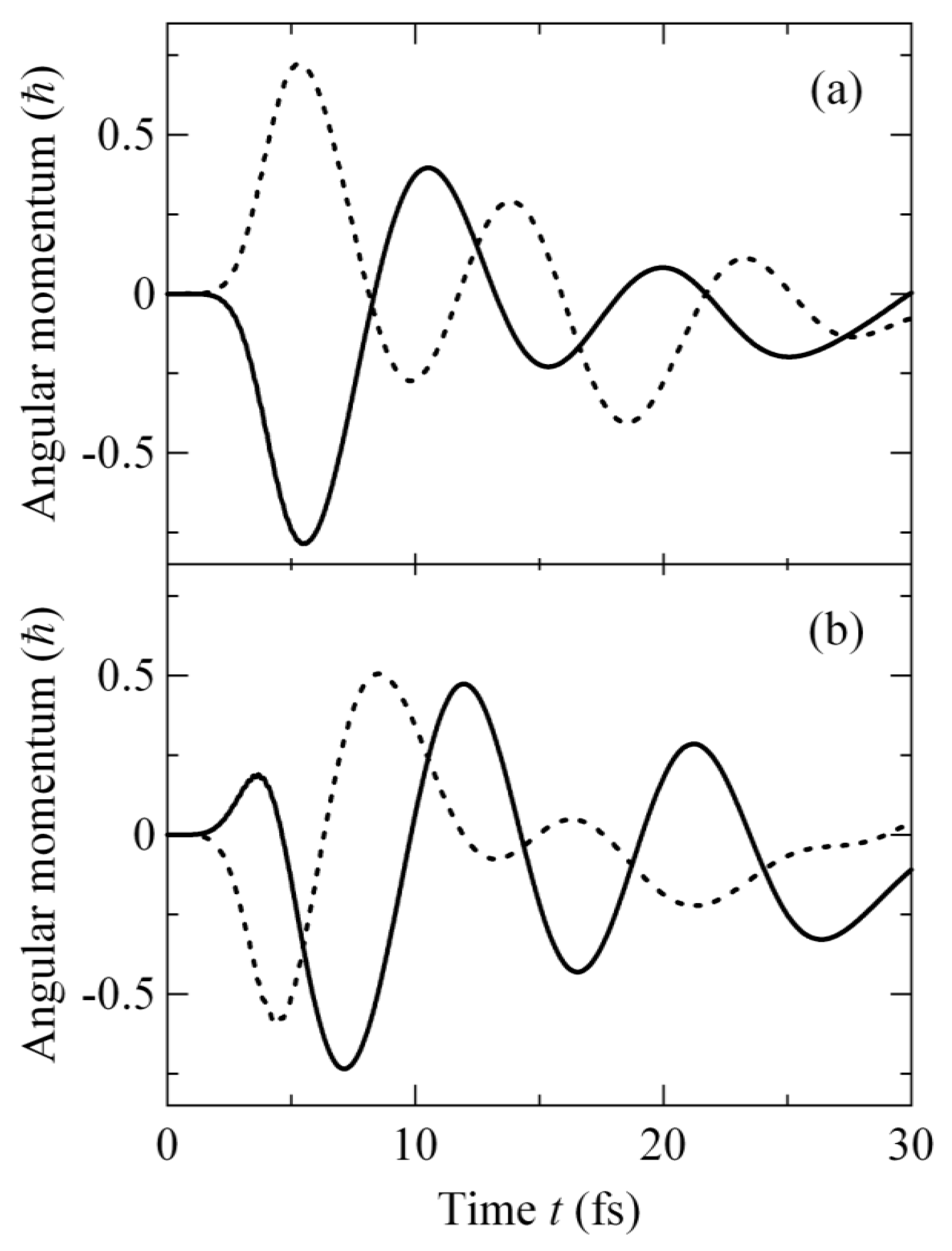
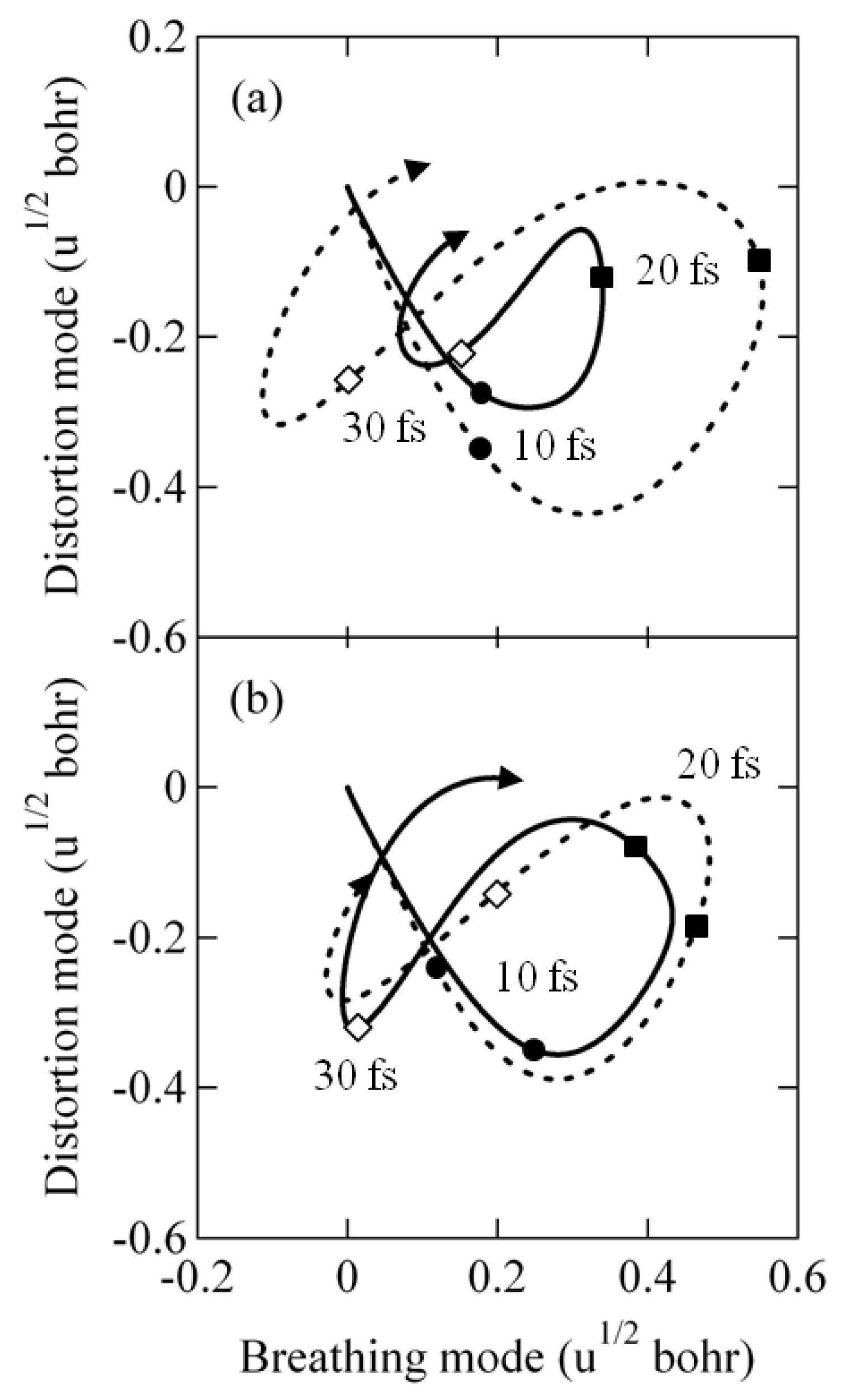
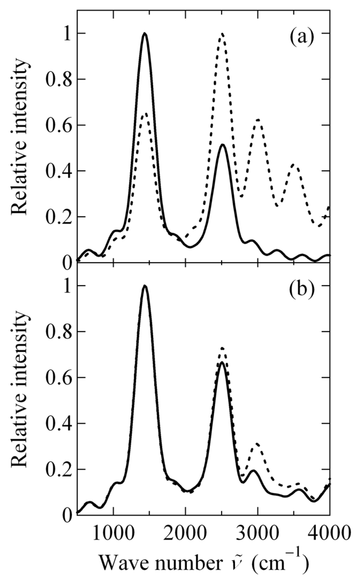
2.3.3. Angular Momentum Expectation Value and Vibrational Spectrum

Figure 5 shows lz(t) for the four types of excitations. Its behavior is analogous to that in Figure 3 while PX(t) PY(t) (t < 4 fs) except for its smaller amplitude due to the less efficiency of excitation and the coordinate dependence of λ(Q). The amplitude of lz(t), however, diminishes gradually, which is a characteristic feature absent in Figure 3. This is ascribed to two factors: decrease of the overlap between the WPs moving on the two excited-state PESs, which occurs even without nonadiabatic couplings, and population transfer due to nonadiabatic couplings shown in Figure 4. Both of the two factors cause the loss of a superposition of | X and | Y ; in particular, the latter contributes to the loss dominantly. Indeed, we performed nuclear WP simulations within the Born-Oppenheimer approximation (BOA) [83], where the WPs simply propagated on the individual PESs, and found that the amplitude of lz(t) exhibits periodic reduction and recovery in turn owing to the temporal change in the WP overlap but never decays monotonically [56,57,58]. The curves of lz(t) for e(+) and e+1 can be approximated by a sinusoidal exponential decay. The lifetime of the decay is ~6 fs for e(+) and ~18 fs for e+1; this difference stems from the different rates of nonadiabatic transition in Figure 4a,c. Meanwhile, the amplitudes of lz(t) for e(−) and e−1 do not undergo a monotonic decrease but make a small transient recovery [in the time ranges of t ~ 14–20 fs for e(−) and t ~ 18–24 fs for e−1]. This arises from the regeneration of the superposition of | X and | Y due to the upward population transfer in the respective time ranges in Figure 4b,d. We also noticed that lz(t) oscillates with slightly different periods among the four types of excitations. The oscillation period of lz(t) is determined by the energy gap between the two PESs in the region where the WPs run; the region depends on the applied pulse as will be shown in Section 2.3.4. The results in Figure 5 demonstrate that nonadiabatic couplings weaken laser-driven ring currents within tens of femtoseconds.
Figure 6 displays the expectation value of the normal coordinates Q ( t ) Ψ ( t ) | Q ^ | Ψ ( t ) with Q ^ being the operator of Q. As seen in Figure 6a, the behaviors of Q(t) for linear polarizations are strongly dependent on the polarization direction: The vibrational amplitude for e(−) is more than two-times as large as that for e(+). In contrast, in Figure 6b, the trajectories of Q(t) for circular polarizations (e+1 and e−1) differ only a little and are located between those for linear ones. The behavior of Q(t) hardly depends on laser polarization under the BOA [56,57,58], which implies the importance of nonadiabatic couplings. The frequency spectrum of ψ X ( Q , t ) after the nonadiabatic transition from | Y to | X can be obtained by the Fourier transform of its autocorrelation function [84]:
σ X ( ω ) Re t i t i + u d t e ( i ω 1 / τ ) ( t t i ) d Q ψ X * ( Q , t i ) ψ X ( Q , t ) .
The parameter τ was introduced to smooth the spectra and set to 39.6 fs, which is longer than the vibrational periods of the breathing and distortion modes (28.8 and 21.2 fs). The values of ti for e(+), e(−), e+1, and e−1 were 14.0, 10.0, 34.0, and 13.0 fs, respectively, and u = 99.1 fs for all of them. The zero of ω was set to the minimum of the lower PES.
The frequency spectra for the four types of excitations are depicted in Figure 7. For e(+), the maximum of σ X ( ω ) is identified at ν ˜ ~ 1400 cm−1 and another peak emerges at ν ˜ ~ 2500 cm−1 in Figure 7a; for e(−), the strongest peak of σ X ( ω ) is located at ν ˜ ~ 2500 cm−1 and a couple of strong peaks are also found at ν ˜ > 3000 cm−1. The wave numbers of 1400, 2500, and 3000 cm−1 are almost equal to those of the lowest three vibrational states in | G owing to the analogy between | G and | X in the PES around its minimum. The frequency spectra for linear polarizations in Figure 7a corroborate that at t > ti, ψ X ( Q , t ) mainly consists of low (high) vibrational states for e(+) [e(−)]. The spectral features for circular ones in Figure 7b are very similar to each other: The primary peaks of σ X ( ω ) for e+1 and e−1 are both at ν ˜ ~ 1400 cm−1, while the intensities of the other peaks are a little stronger in the latter case. This indicates that ψ X ( Q , t ) is composed of the same frequency components for e+1 and e−1 in the time domain after the nonadiabatic transition.
The remarkable difference in the vibrational amplitude between e(+) and e(−) suggests that ring currents in aromatic molecules such as DCP irradiated by linearly polarized laser pulses can be distinguished experimentally by vibrational spectroscopy in the frequency domain without time-resolved measurements. This suggestion may be useful for rapid identification of molecular chirality. For instance, if two enantiomers of a polar chiral molecule are oriented so that their permanent dipoles are parallel to each other, the linear polarization vector e(+) or e(−) designed for one of the enantiomers does not necessarily coincide with that for the other enantiomer. Therefore, the strength of the induced ring current should be different between the enantiomers and the current direction can be opposite. This difference will be reflected in vibrational motions of the enantiomers.

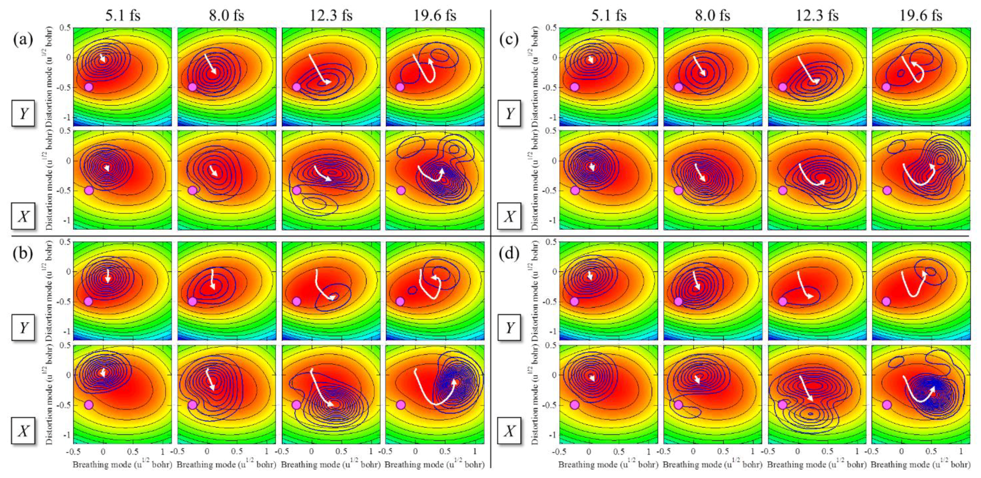
2.3.4. Laser Control of Wave Packet Interference

Figure 8 shows the propagations of the adiabatic WPs on the two excited-state PESs. The probability densities | ψ X ( Q , t ) | 2 and | ψ Y ( Q , t ) | 2 at t ~ 5 fs resemble that of the initial WP in | G and then the WPs start to move along the gradient of each PES. As they approach the avoided crossing, the nonadiabatic effects on vibronic dynamics appear differently for the four types of excitations. For e(+) (Figure 8a), the WP in | Y is diminished by nonadiabatic transition at t ~ 12 fs and the contour map of | ψ X ( Q , t ) | 2 clearly displays the node arising from the interference; thereafter, the WPs on the two PESs are distorted significantly. In contrast, for e(−) (Figure 8b), the WPs maintain a Gaussian-like form even after the nonadiabatic transition already in progress at t ~ 8 fs. For circular polarizations, the WPs behave as expected from the behavior of the populations in Figure 4c,d. In the case of e+1 (Figure 8c), only a small fraction of ψ Y ( Q , t ) has been transferred to | X until t ~ 12 fs and no interference patterns are observed in the WPs. For e−1 (Figure 8d), the WPs exhibit intermediate features between those for e(+) and e(−): No clear interference is observed in the WPs but the shape of | ψ X ( Q , t ) | 2 is deformed from a Gaussian especially at t ~ 12 fs. As a result of nonadiabatic couplings, the center of ψ X ( Q , t ) , which contributes dominantly to Q(t) in Figure 6, runs in a low-energy (high-energy) region on the PES for e(+) [e(−)], whereas the motions of the center for circular polarizations are similar to each other.
The polarization effects on the expectation values lz(t) and Q(t) as well as on the populations PX(t) and PY(t) can be explained in terms of WP interference. As defined in Section 2.2, a linearly polarized laser pulse with e(−) initially produces a superposition of ψ X ( Q , t ) and ψ Y ( Q , t ) out of phase (θ = π). Their relative quantum phase evolves during irradiation [by −ϑ(t) in the rectangular-envelope cases] and also gains a dynamical phase associated with the shape of each PES as the WPs propagate. In nonadiabatic transition, an additional phase shift is further imposed on the WP created by nonadiabatic couplings, which interferes with that on the other PES. We do not quantify the additional phase in DCP, but the downward population transfer around t ~ 5–10 fs in Figure 4b implies opposite interferences on the two PESs: The WPs are almost in phase and interfere constructively on the lower PES, while those on the higher PES are out of phase with destructive interference. The constructive interference on the lower PES works particularly on high vibrational states in ψ X ( Q , t ) . The direction of the population transfer flips as the relative quantum phase grows.
For e(+), the WPs prepared on the two PESs are in phase (θ = 0). The effects of WP interference are therefore reversed from those for e(−): For DCP, the interference is destructive on the lower PES but constructive on the higher one around t ~ 5–10 fs. The amount of the WP created by the nonadiabatic transition from | X to | Y , which interferes with ψ Y ( Q , t ) , is smaller than that for the transition from | Y to | X , which interferes with ψ X ( Q , t ) ; this is the reason why the resultant upward population transfer is small in Figure 4a. The WPs on the two PESs then reach the avoided crossing and the reverse population transfer occurs around t ~ 10–14 fs. The interference enhances low vibrational states in ψ X ( Q , t ) .
In the cases of circular polarizations, ψ X ( Q , t ) and ψ Y ( Q , t ) are initially neither in phase nor out of phase because θ = ± (ηYηX) for e±1; for DCP, θ = ± 0.35π. Hence, no fully constructive or destructive interference takes place on either PES at t ~ 5–10 fs, resulting in the vibrational amplitudes in Figure 6b, which are intermediate between those for e(+) and e(−) in Figure 6a. As the relative quantum phase of DCP evolves in the negative direction, for e−1 (θ = − 0.35π), it takes more time than for e(−) (θ = π) but less time than for e(+) (θ = 0) to experience constructive and destructive interferences on the lower and higher PESs, respectively. As a consequence, the downward population transfer for e−1 appears at t ~ 8–13 fs in Figure 4d. For e+1 (θ = 0.35π), the WPs pass through the avoided crossing before the requirement of interference for population transfer is met; the nonadiabatic transition is therefore not completed until they come closer again to the avoided crossing at t ~ 30 fs as in Figure 4c.
The present results indicate that the initial relative phase θ governs not only ring currents but also the subsequent molecular vibration through nonadiabatic couplings. Furthermore, it is possible to control the time-dependent phase due to irradiation, i.e., ϑ(t) by adjusting the other laser parameters such as the peak field strength E0 and pulse duration tf. This suggests that a superposition of the quasi-degenerate states with an arbitrary relative phase can be created by applying a laser pulse of arbitrary polarization. The interference between nuclear WPs in nonadiabatic transition can be controlled as desired by attosecond/several-femtosecond laser pulses, leading to sophisticated control of molecular vibrations.

3. Coherent π-Electron Angular Momentum and Current of a Molecule Having Two Aromatic Rings

So far, we have considered the coherent quantum dynamics of π electrons in aromatic molecules with a single aromatic ring [55,56,57,58,60,61,62,85]. In this section, we present the results of a theoretical study on coherent quantum dynamics of π electrons in a molecule with two aromatic rings. For such an aromatic molecule, ultrafast coherent π-electron dynamics that cannot be induced in a molecule with a single aromatic ring appears. Typical examples of the coherent π-electron dynamics are localization of angular momentum (ring current) at a specific aromatic ring and transfer of localized angular momentum (ring current) from one of the aromatic rings to the other one. Localization of π-electron rotation driven by pulsed lasers is expected to play an essential role in the development of organic optoelectronic switching devices for next generation as well as femtosecond and attosecond chemistry [86].

3.1. Two Ring Components of π-Electron Angular Momentum and Current

In this subsection, first, we derive an expression for the coherent π-electron angular momentum of aromatic ring molecules and that for the ring current by using the density matrix method [87]. Next, we apply the theoretical expressions to (P)-2,2′-biphenol as a real chiral molecule with two benzene rings. This is a typical nonplanar aromatic ring molecule with axial chirality.

3.1.1. Decomposition of Angular Momentum and Current into Atomic Orbital Components

The expectation values of the coherent electronic angular momentum and current operators of an aromatic ring molecule excited by visible or UV light are expressed as [87]
O ^ ( r , t ) = n d 3 r 1 d 3 r n δ ( r r 1 ) Ψ * ( t ) O ^ ( r 1 ) Ψ ( t ) .
Here, O ^ ( r 1 ) is a one-electron operator for the angular momentum or current, Ψ(t) is an electronic wave function at time t, n is the number of electrons, and r i denotes the electron coordinates of the i-th electron.
Ψ(t) is expanded in terms of electronic configurations, the ground electronic Φ0 and singly excited electronic ones Φα, as Ψ ( t ) = C 0 ( t ) Φ 0 + α C α ( t ) Φ α . Here, Φ0 is given as Φ 0 ( r 1 , , r n ) = ϕ 1 ϕ a ϕ b ϕ n with ϕ n ϕ n ( r n ) . ϕ a and ϕ b are among the n occupied orbitals, and Φα is given as Φ α ( r 1 , , r n ) = ϕ 1 ϕ a ϕ n , which represents a single-electron transition from occupied MO a to unoccupied MO a′. Within a linear combination of atomic orbitals-molecular orbitals (LCAO-MO) approximation, a π orbital ϕ k is expanded as ϕ k = i c k i χ i (k = a, a′, b, b′), where χi is i-th AO and cki is the MO coefficient.
Equation (35) can be expressed within the MO approximations as follows:
O ^ ( r , t ) = 2 i n α < β Im ρ β α ( t ) i j ( δ a b c a i * c b j + δ a b c a i * c b j ) χ i * O ^ ( r ) χ j ,
where the electronic-state density matrix element ραβ(t) is defined as ρ α β ( t ) C α ( t ) C β * ( t ) . Let us now express the expectation value of the coherent angular momentum operator and that of ring current operator of a space-fixed aromatic ring molecule with two aromatic rings connected with a single bond.

3.1.2. Coherent Angular Momentum

The total electron angular momentum operator of an aromatic ring molecule can be expressed as a sum of the angular momentum operator of each aromatic ring, which is defined as O ^ ( r ) = l z L + l z R , where l z K [ i ħ ( x K / y K y K / x K ) n K ] is the electronic angular momentum operator of the z-component of ring K (= L or R). Here, L and R denote the ring on the left-hand side and that on the right-hand side, respectively. Coordinates xK and yK operate on AOs belonging to ring K, and n K is the unit vector perpendicular to the ring. The expectation value of the angular momentum operator is given, for example, in terms of a 2pz carbon AOs as [87]:
l ( t ) = d 3 r L l z L + d 3 r R l z R l L ( t ) + l R ( t ) ,
where
l K ( t ) d 3 r K l z K = 2 n ħ n K α < β Im ρ β α ( t ) i j K ( δ a b c a i * c b j + δ a b c a i * c b j )      × x K , i y K , j x K , j y K , i 15 a 2 2 [ 3 + 3 ( r i j a 2 ) + ( r i j a 2 ) 2 ] exp ( r i j a 2 ) .
Here, a2 is a constant related to the orbital exponent of the 2pz AO and rij is the distance between i and j carbon atom sites.

3.1.3. Coherent Ring Current

The ring current passing through a surface S at time t is defined as follows:
J ( t ) S d 2 r n J ^ ( r , t )
Here, n is a unit vector perpendicular to surface S, and J ^ ( r , t ) Ψ ( t ) | J ^ ( r ) | Ψ ( t ) , which can be expressed as:
J ^ ( r , t ) = 2 i n α < β Im ρ β α ( t ) i j ( δ a b c a i * c b j + δ a b c a i * c b j ) χ i * J ^ ( r ) χ j       = 2 n e ħ m e α < β Im ρ β α ( t ) i j ( δ a b c a i * c b j + δ a b c a i * c b j ) χ i * χ j ,
where J ^ ( r ) = ( e ħ / 2 m e i ) ( ) is the current density operator. Here, ( ) denotes the nabra operating on the AO on the right-hand (left-hand) side. Surface integration in Equation (39) is carried out over a planar plane S perpendicular to a C–C bond of an aromatic ring.
Since the L and R rings are not round but consist of nonequivalent C–C bonds, we introduce the bond current J ( t ) i j from the nearest neighbor atoms at sites j to i, which is given in terms of inter-atomic bond current (IABC) J i j I A B C as
J ( t ) i j = 2 n e ħ m e α < β Im ρ β α ( t ) [ δ a b ( c a i * c b j c b i * c a j ) + δ a b ( c a i * c b j c b i * c a j ) ] J i j I A B C ,
where
J i j I A B C = S d 2 r χ i * n χ j [ J i j I A B C ( S   a t   c e n t e r ) ]
Here, surface S is set to be perpendicular to the Ci and Cj bond at the center.
Equation (42) is given in the 2p carbon AO basis set, {χi}, as [87]:
J i j I A B C ( S   a t   c e n t e r ) = r i j cos Θ 2 a 2 6 0 d r r 3 exp ( 2 r i j 2 / 4 + r 2 / a 2 ) r i j 2 / 4 + r 2 .
Here, Θ = π for the bond current of the chemical bond belonging to one of the two aromatic rings, L or R, while Θ = Θd for the bridge bond current of bond Ci − Cj with a dihedral angle between the two rings Θd. Ci (Cj) refers to the bridge carbon belonging to the R (L) ring.
We now define an effective ring current along ring K, J ( t ) K , by taking the average over all of the bond currents as [87]:
J ( t ) K 1 N K ( i j ) K N K J ( t ) i j ,
where NK is the number of bonds of ring K.
Time-dependent behaviors of electronic dynamics induced by a pulsed laser field, E(t), can be directly obtained by solving the coupled equations of motion of ραβ(t) with the initial conditions ρ00(0) = 1 and ραα(0) = 0 for α ≠ 0; ραβ(0) = 0 for αβ (hereafter Greek subscripts refer to electronic states):
d ρ α β ( t ) d t = i ħ γ [ V α γ ( t ) ρ γ β ( t ) ρ α γ ( t ) V γ β ( t ) ] ( i ω α β + γ α β ) ρ α β ( t ) .
Here, Vαγ(t) denotes the coupling between electronic states α and γ through the molecule-field interaction, V ^ ( t ) = μ ^ E ( t ) , ωβα is the angular frequency difference between two electronic states α and β, and γαβ [ = ( γ α + γ β ) / 2 + γ α β ( d ) ] is the dephasing constant in Markov approximation [88]. Here, γα (γβ) is the nonradiative transition rate constant of state α (β), and γ α β ( d ) is the pure dephasing constant that is induced by elastic interactions between the molecule of interest and heat baths including intramolecular vibrations.

3.1.4. Application to (P)-2,2′-Biphenol

For generation of coherent angular momentum and ring current of (P)-2,2′-biphenol, we focus on the three optically allowed excited states (a, b1, and b2) whose energies range from 6.67 to 6.84 eV as shown in Figure 9a [87]. The geometry of (P)-2,2′-biphenol in the ground state was optimized by using the density functional theory (DFT) at the B3LYP level of theory in the GAUSSIAN09 program [89]. (P)-2,2′-biphenol was assumed to be fixed on a surface by a non-conjugated chemical bond or in a space by laser molecular orientation techniques. The laboratory-fixed Y-axis is set to be parallel to the single bond bridging the two phenol groups, and the rotation axis of point group C2 is placed along the laboratory-fixed Z-axis parallel to the surface normal. The dihedral angle between the two phenol groups, Θd, was found to be 108.9 degrees from our DFT calculations [86].
The transition energies to the a (A), b1 (B), and b2 (B) states, which were calculated at the optimized ground state geometry using the time-dependent DFT at the B3LYP level of theory, are 6.67, 6.78, and 6.84 eV, respectively [86]. Figure 9b shows the directions of transition dipole moments. The three optically allowed excited states associated with the present laser-induced electron dynamics have one-electronic excitation configurations since they basically consist of optically allowed ππ* excited states of the two phenol rings. The transition dipole moment from the ground state to excited state a (A), μga [= (0, 0, −0.77) in atomic units], is parallel to the Z-axis, and the others, μgb1 [= (0.08, 1.93, 0)] and μgb2 [= (1.24, −0.34, 0)], are nearly orthogonal to each other in the XY-plane as shown in Figure 9.

3.1.5. Generation of Two-State Electronic Coherence by Linearly Polarized UV Pulses

We can generate three types of two-state electronic coherence in the present three excited state model, which can be represented as (b1 ± b2), (a ± b1), and (a ± b2). The phase of each electronic coherence can be set by applying a linearly polarized UV laser pulse with a properly selected polarization direction. Because of the nonplanar geometrical structure, the angular momentum is two-dimensional and the ring current is on two different surfaces: Z-directional angular momentum is generated for the created coherent state with A symmetry and corresponding ring current is generated on the Z-directional angular momentum, while X-directional angular momentum is generated for the coherent state with B symmetry and ring current is generated on the X-directional angular momentum.
Figure 10 shows time-dependent angular momenta calculated for three types of electronic coherence, (b1 + b2), (a + b1), and (a + b2), each of which is created by a linearly polarized UV pulse with a properly selected polarization direction. The envelope function of the pulse for each coherence is shown in the right-hand side. The pulse amplitudes for (b1 + b2), (a + b1), and (a + b2) coherences are 0.19, 0.83 and 3.32 TW/cm2, respectively. Angular momentum along the Z-axis, lZ, is generated for (b1 + b2) electronic coherence, while those along the X-axis, lX, are generated with π-phase shift for (a + b1) electronic coherence as well as (a + b2) electronic coherence. Similarly, for out-of-phase electronic coherences (b1b2), (ab1), and (ab2), each angular momentum can be expressed by that for the corresponding in-phase coherence with π-phase shift. The time-dependent angular momenta in the Z and X directions are, respectively, expressed in terms of l L ( t ) as l Z ( t ) = 2 l L ( t ) sin ( Θ d / 2 ) and l X ( t ) = 2 l L ( t ) cos ( Θ d / 2 ) . l Z ( t ) was calculated using the relation lL(t) = lR(t) and l X ( t ) was calculated using lL(t) = −lR(t) as shown in Figure 10. The simple sinusoidal time-dependence with a damping originates from creation of two-state electronic coherence, the oscillation period of which corresponds to the frequency difference between the two states. The damping behaviors of the oscillation amplitudes are due to dephasing between the two excited states. Here, dephasing constants γab1 = γab2 = γb1b2 = 0.01 eV were adopted [87]. The oscillations in the angular momenta should be called angular momentum quantum beats, similar to quantum beats originating from vibronic coherence in fluorescence [90]. It should be noted that in angular momentum quantum beats, π electrons rotate in a unidirectional way a few times within the half cycle of the oscillation. The unidirectional π-electron rotation can produce unidirectional ring current and current-induced magnetic flux. This is the basic principle to design ultrafast switching devices made from organic ring molecules.

3.1.6. Bond Currents and Time Evolution of Coherent Ring Current

Figure 11 shows the magnitudes of bond current, Jij, which were calculated using Equation (42) at the maximum coherence time together with the directions of bond currents for the three types of electronic coherence in the first period of oscillation. The arrow along each bond of (P)-2,2′-biphenol denotes the initial direction of the bond current. Magnitudes of the averaged ring current at the maximum coherence time are of an order of tens of μA: J ¯ = 161, 86.5 and 63.4 μA for (b1 + b2), (a + b1), and (a + b2) coherences, respectively [87]. If the phenol ring is assumed to be a ring with radius r and the magnitude of the angular momentum l = rp with linear momentum of electrons, p, is given, the ring current J can be estimated by using the relation 2πrJ = ep/me. The magnitudes of the ring currents for the (b1 + b2), (a + b1), and (a + b2) coherences are 216, 163.5 and 25.5 μA, respectively. The magnitude of each ring current is large compared with that of the corresponding averaged ring current except for (a + b2) coherence. The difference in the magnitudes between the averaged bond current at the maximum coherence time and the ring current calculated within a perfect ring model mainly originates from the fact that phenol ring has a functional OH group. Barth et al. reported an electronic current of 84.5 μA for Mg porphyrin excited by a circularly polarized UV intense laser pulse to yield population inversion [51]. It is interesting that (P)-2,2′-biphenol and Mg porphyrin have the same order of magnitude in ring currents, though they have different numbers of electrons and different radii of their rotation.

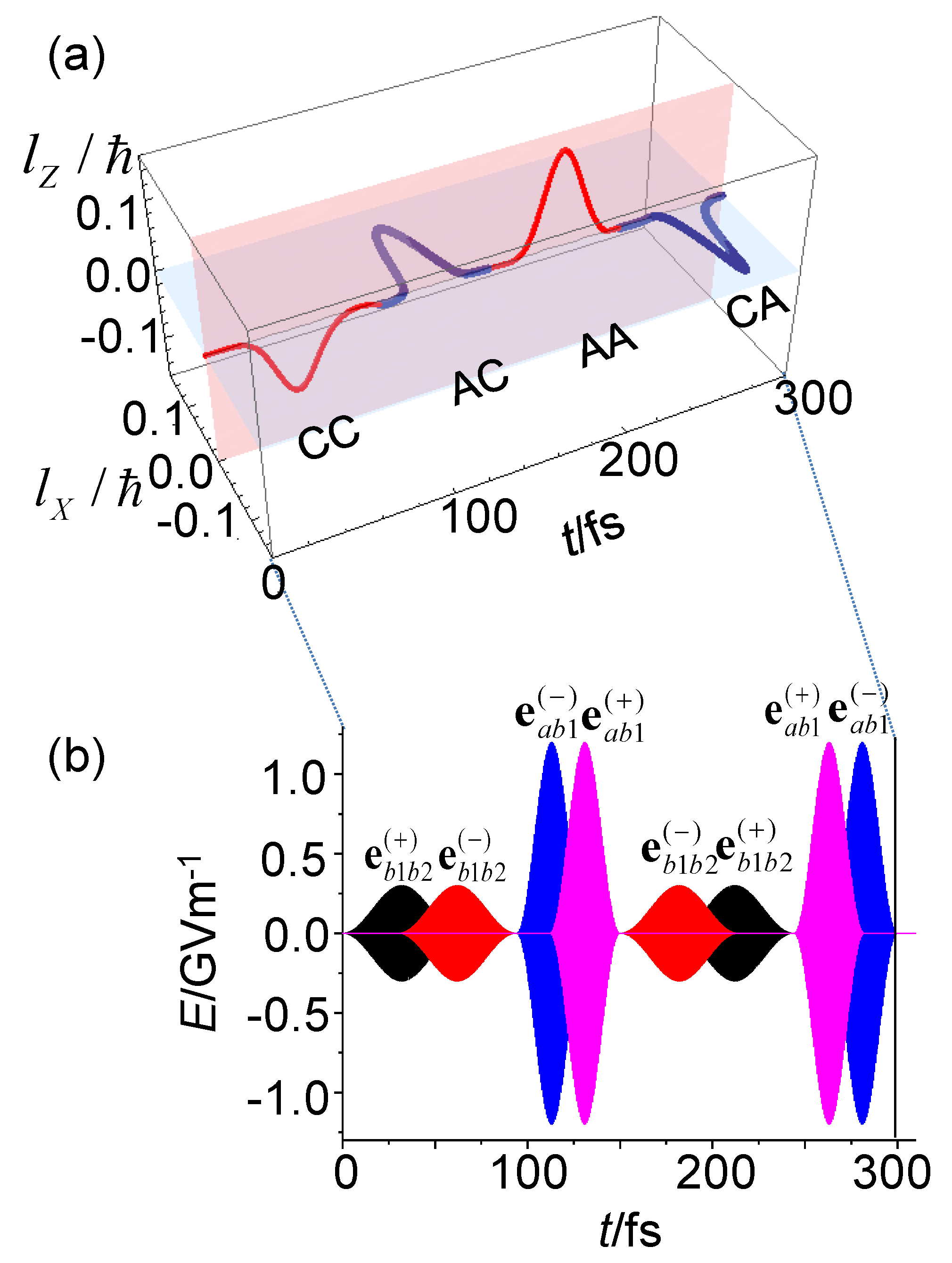
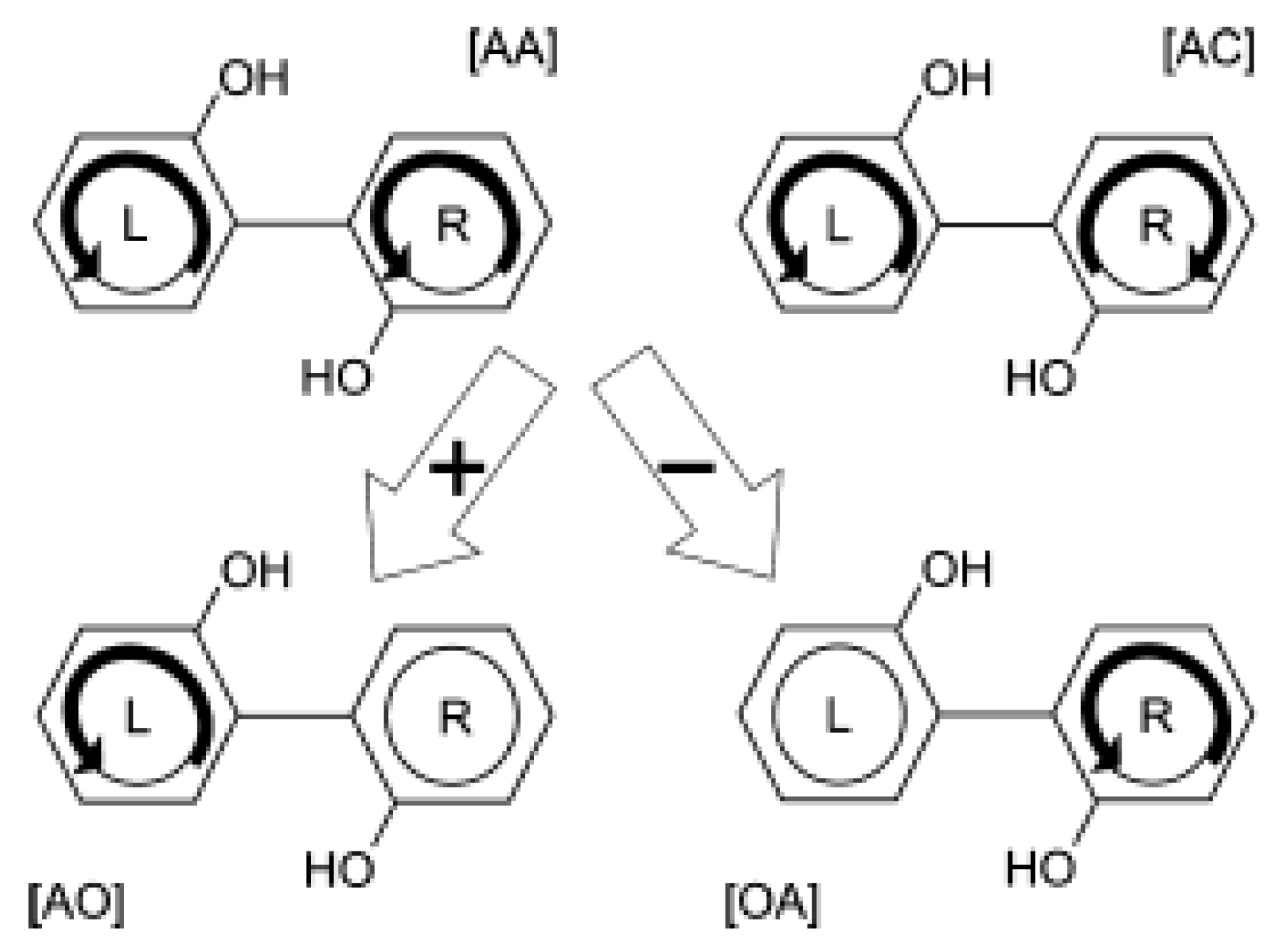
3.2. Quantum Switching of Coherent π-Electron Rotations in a Nonplanar Chiral Aromatic Molecule

In general, π electrons in a planar aromatic molecule generate electronic angular momentum perpendicular to their aromatic ring. In a nonplanar aromatic ring molecule, on the other hand, it is possible for π electron rotations to generate multi-dimensional angular momenta, each component of which has a particular angular momentum vector with a definite direction and generates the corresponding angular momentum. Therefore, nonplanar aromatic ring molecules are promising as a sophisticated switching device with several controllable variables [86].

3.2.1. Control Scheme for Angular Momentum Switching

As shown in Figure 12a, four rotational patterns (CC, AA, CA, and AC), in which C (A) means clockwise (anticlockwise) rotation along the L or R phenol ring, are possible for (P)-2,2′-biphenol, depending on two factors: one is the polarization direction of the applied linearly polarized laser pulse and the other is the symmetry of the created coherent state. Let us first clarify how these patterns can be prepared, and then how ultrafast switching between these rotational patterns can be realized. As already shown by Equation (31), the polarization direction is expressed in terms of a unit vector, e α β ( + ) or e α β ( ) with α, β = a, b1, b2. Here, e α β ( + ) and e α β ( ) are defined by e α β ( + ) μ g α = e α β ( + ) μ g β and e α β ( ) μ g α = e α β ( ) μ g β , respectively. The excitation by laser pulses with e α β ( + ) [ e α β ( ) ] creates a linear combination of two electronic states α and β with their in-phase (out-of-phase) relation, which is called e α β ( + ) [ e α β ( ) ] excitation hereafter. The schematic drawings on the left-hand side of Figure 12a represent the initial rotational directions of π electrons after the preparation of a superposition of the two excited states, b1 and b2. The upper (lower) drawing shows the rotational direction just after coherent e b 1 b 2 ( + ) [ e b 1 b 2 ( ) ] excitation, which indicates CC (AA) rotation, i.e., π electrons start to rotate along the two phenol rings in the same directions.
Figure 12b shows the resultant angular momentum l = lL + lR. Here, the π-electron angular momentum lL (lR) is perpendicular to the L (R) phenol ring, and the resultant total angular momentum lZ (lX) is parallel to the Z- (X-) axis on the ZX-plane. The directions of lZ indicate that clockwise (anticlockwise) rotation around the Z-axis is created by e α β ( + ) [ e α β ( ) ] excitation. The schematic drawings on the right-hand side of Figure 12a (12b) represent π-electron rotations (the resultant angular momenta) after preparation of a superposition of the two excited states, a and b1, with different irreducible representations. π Electrons start to rotate along the two phenol rings in opposite directions to each other (CA or AC rotation). Therefore, the total angular momentum parallel to the Z-axis is zero and the nonzero resultant angular momentum lX is generated along the X-axis on the ZX-plane. If the two phenol rings are in the same plane without twist, both lX and lZ vanish. Furthermore, e a b 1 ( + ) and e a b 1 ( ) excitations induce CA and AC rotations, respectively. Let us now consider two-dimensional current switching on the basis of the results shown in Figure 12. Here, two-dimensional switching means a sequential variation of electronic angular momentum with its definite sign (plus or minus) along the Z- or X-axis. The switching should be carried out before reverse rotation of π electrons begins since the prepared coherent states are not eigenstates. For this purpose, we take a sequential four-step control as an example, indicated as lZ (−) → lX (+) → lZ (+) → lX (−), which is generated by the switching of rotational patterns CC → AC → AA → CA. Here, lZ (−) [lX (+)] denotes the π-electron angular momentum along the Z- (X-) axis with a negative (positive) sign, i.e., clockwise (anticlockwise) rotation of π electrons around the corresponding axis.

3.2.2. Simulation Results of Angular Momentum Switching

Figure 13a shows a 3D plot of the resultant angular momentum switching based on the sequential four-step scheme, which demonstrates that π-electron rotations are successfully controlled by the pulses depicted in Figure 13b. Control at each switching step was carried out by using pump and dump pulses with specific polarization directions. The pulsed laser with amplitude of 1.2 GV/m (= 1.9 × 10¹¹ W/cm2) [14] was used at the second and fourth steps [86].
The pulses shown in Figure 13b have two features: firstly, the pump (dump) pulse for each step has e α β ( + ) [ e α β ( ) ] or e α β ( ) [ e α β ( + ) ] polarization. Each pulse has a bandwidth that is sufficient to coherently excite two quasi-degenerate electronic excited states. Secondly, the pump and dump pulses partially overlap. For the first step, i.e., creation of CC rotation, for example, the electric field of the pump pulse was given as e b 1 b 2 ( + ) ( t ) = E b 1 b 2 ( + ) E b 1 b 2 0 sin 2 ( π t / T b 1 b 2 ) sin ( ω c , b 1 b 2 t ) , while that of the dump pulse was E b 1 b 2 ( ) ( t ) = e b 1 b 2 ( ) E b 1 b 2 0 sin 2 [ π ( t t b 1 b 2 p d ) / T b 1 b 2 ] sin ( ω c , b 1 b 2 t + π / 2 ) [86]. Here, E b 1 b 2 0 is the amplitude of the pulse, Tb1b2 (= 60.9 fs) is the oscillation period between the two excited states, b1 and b2 states, ωc,b1b2 is the central frequency between the two excited states, and t b 1 b 2 p d , the time interval between the pump and dump pulses, was set to Tb1b2/2. The angle between the two polarization directions, i.e., e b 1 b 2 ( + ) and e b 1 b 2 ( ) , is 113.5°.
For the present ultrafast quantum switching, overlap between the pump and dump pulses is essential: the resultant electric field is rotated as an elliptically polarized one in the overlapped region, and the electric field forces the rotating π electrons to induce the reverse rotation that occurs in this region. As a result, the electronic angular momentum of the π electrons is erased.

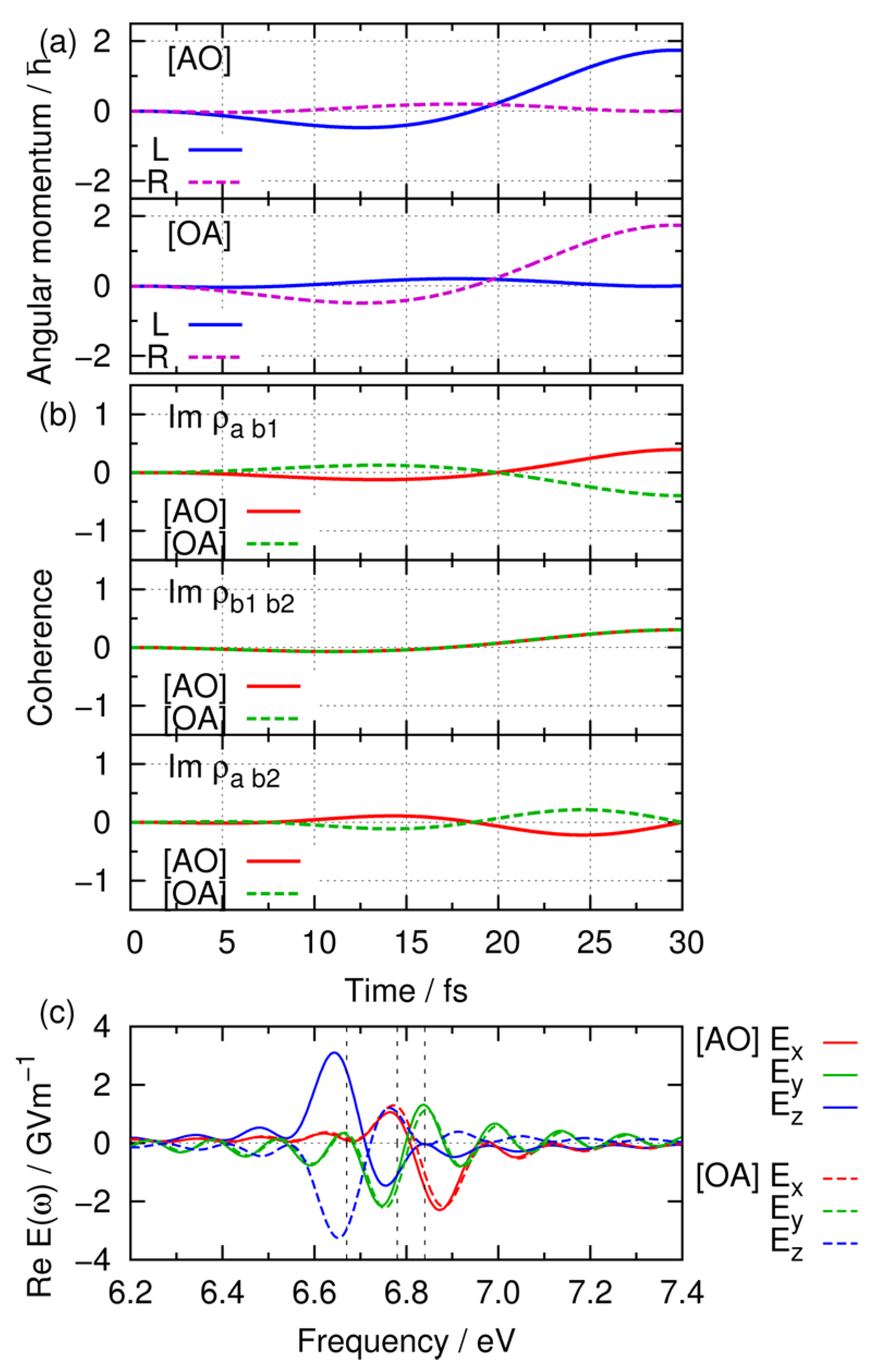
3.3. Quantum Localization of Coherent π-Electron Angular Momentum

In this subsection, we briefly describe the fundamental concept of a quantum localization of coherent π-electron angular momentum (ring current) in aromatic ring molecules and demonstrate the quantum localization by numerical simulations [91]. As an example, we again take (P)-2,2′-biphenol. The localization considered here consists of sequential two steps: the first step is to localize the π-electron angular momentum at a selected ring of the two benzene rings, and the other is to maintain the localization. Optimal control theory was used for obtaining the optimized electric fields of linearly polarized laser pulses to realize the localization. The optimal electric fields and the resultant coherent electronic dynamics were analyzed. The target molecule was assumed to be fixed on a surface by a (CH2) chain free from π electrons.

3.3.1. Optimal Control Theory

Localization of π-electron angular momentum can be intuitively understood from the coherent character of the four patterns of coherent π-electron rotations as shown in Figure 14. Here, each pattern is generated by rotations of π electrons localized at the two benzene rings with a definite rotational phase. We now outline optimal control procedure [92,93,94]. Quantum dynamics of π electrons induced by the electric field of a laser pulse E(t) is described by the Hamiltonian:
H ^ ( t ) = H ^ 0 μ ^ E ( t )
Here, H ^ 0 is the π-electronic Hamiltonian of (P)-2,2′-biphenol in the free field. For simplicity, effects of molecular vibrations on electron dynamics are omitted. Let us take an objective functional defined as:
J [ E ] = ν Ψ ( t f ) | O ^ | Ψ ( t f ) + 1 ν t f 0 t f d t Ψ ( t ) | O ^ | Ψ ( t ) 0 t f d t E ( t ) 2 ħ α ( t ) .
where, O ^ is a projection operator for the target state of interest, tf is the final (control) time, α(t) is a time-dependent penalty factor to suppress the intensity of the optimal field, and ν (= 0 or 1) is a parameter to switch the objective functionals. For ν = 1, the target population is maximized at the final time, and on the other hand, for ν = 0 the time-integrated population of the target state is maximized. Equation (47) is to be maximized with a constraint of the time-dependent Schrödinger equation:
i ħ t | Ψ ( t ) = H ^ 0 | Ψ ( t ) ,
with the initial condition | Ψ ( 0 ) = | G . Here, | G denotes the ground state. After taking the variation in Equation (47), we obtain the optimal electric field as:
E ( t ) = α ( t ) Im ξ ( t ) | μ ^ | Ψ ( t ) ,
Here, ξ(t) is time-dependent Lagrange multiplier, which satisfies a time-dependent equation:
[ i ħ t H ^ ( t ) ] | ξ ( t ) = ( ν 1 ) i ħ t f O ^ | Ψ ( t ) ,
with the final condition | ξ ( t f ) = ν O ^ | Ψ ( t f ) .
In order to carry out quantum control simulation for localization of the π-electron angular momentum of (P)-2,2′-biphenol, we need a set of angular momentum eigenstates defined in each aromatic ring. The localized angular momentum eigenstates ( W K A and W K C with K = L, R) can be expressed in terms of the three excited states (Φa, Φb1, Φb2) as [91]:
( W L A W L C ) = ( 0.56 0.71 i 0.43 0.56 0.71 i 0.43 ) ( Φ a Φ b 1 Φ b 2 ) ,
( W R A W R C ) = ( 0.56 0.71 i 0.43 0.56 0.71 i 0.43 ) ( Φ a Φ b 1 Φ b 2 ) .
The transformation matrices in the above equations were calculated by using the electronic angular momentum operator. The target states for the optimal control are, for example, expressed as follows: O ^ = | W L A W L A | for the [AO] localization and O ^ = | W R A W R A | for the [OA] localization. Here, O means no rotation on the L or R ring.

3.3.2. Simulation Results of Angular Momentum Localization

Figure 15 shows the quantum control results of the first step for the localization of angular momentum. The control time was set to tf = 30 fs, which is the inverse of the energy differences between two electronic excited states. In Figure 15a, the expectation value at tf = 30 fs, lL(tf) [lR(tf)], reaches the maximum value for the [AO] ([OA]) target, while that of lR(tf) [lL(tf)] is suppressed to zero. This demonstrates that the π-electron localization on one benzene ring is successfully achieved. Figure 15b represents the time-dependent electronic coherences, i.e., imaginary parts of ρab1(t), ρb1b2(t), and ρab2(t). The imaginary part of ρb1b2(t) for the [AO] and that for [OA] targets provide the same time dependence, while the imaginary parts of ρab1(t) and ρab2(t) for the [AO] target are shifted by π compared to those for the [OA] target. These phase relations originate from that of the target operator in Equation (51). Figure 15c shows Re E(ω), real parts of the optimal electric fields in the frequency domain, for the [AO] target (solid line) and the [OA] target (dashed line). The vertical dotted lines refer to the energies of the three eigenstates. The peaks of EX(ω), EY(ω), and EZ(ω) appeared at the resonant positions of b2, b1, and a states, respectively. The phases of the z-component are shifted by π between [AO] and [OA] targets, while phase shifts for the other two components, EX(ω) and EY(ω), are zero. This indicates that the π-phase shift of the electric field EZ(ω) is the key to control π electron rotations for the [AO] and [OA] localization. It should be noted that EZ(ω) excites only the a state. The difference in the target coefficients between W L A and W R A is that of Φa. This is the reason why the π-phase shift appeared only in the z-component. The phase shift of EZ(ω) results in π-phase shift in coefficients of Φa, Φb1, and Φb2, and finally the [AO] and [OA] localizations are realized at t = 30 fs. The maximum amplitude of the optimal field is about 1 GVm−1 (0.13 TWcm−2), which is much lower than the so-called threshold of multiphoton processes [91].

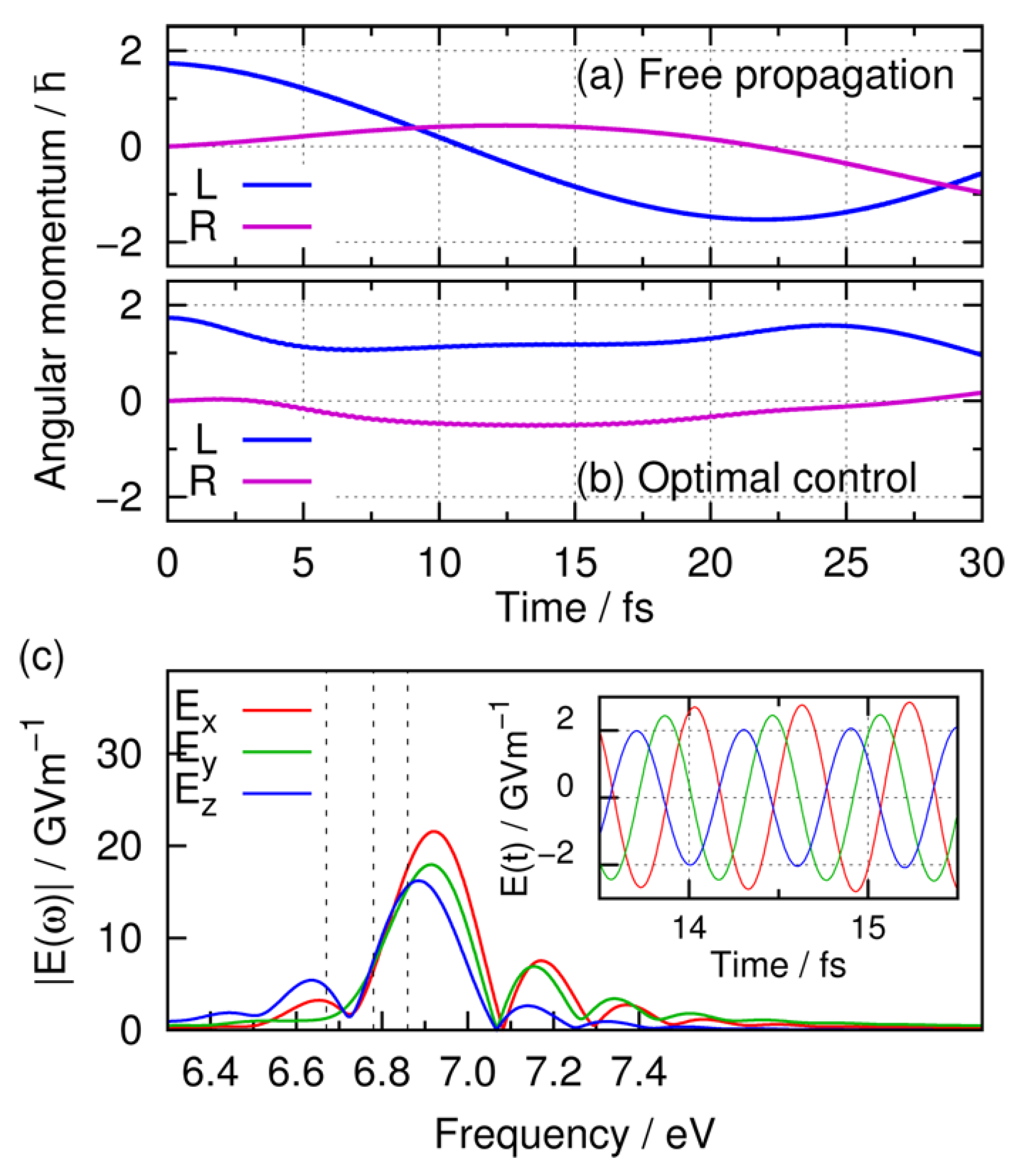
3.3.3. Simulation Results of Maintaining Angular Momentum Localization

Figure 16 shows the quantum control results of the second step for the localization, i.e., maintaining the unidirectional (anticlockwise or clockwise) rotation of π electrons around the L- or R-axis. After the localization has been completed, the localized angular momentum undergoes free propagation if there is no control field. Figure 16a shows the time dependence of the expectation values of the π-electron angular momentum under the field-free condition after the [AO] localization is achieved. Here, the initial time t = 0 was set to be the time when the first step of localization has been achieved. The expectation value of the π-electron angular momentum around the L-axis, lL(t), starts to oscillate, and that around the R-axis, lR(t), deviates from zero and oscillates in the opposite way. Figure 16b shows the results of the second step control to the initial localization demonstrated in Figure 15a. The control time was again set at tf = 30 fs. Figure 16b indicates that lL(t) keeps positive values under the optimal field. It is possible to keep the localization at any longer times tf > 30 fs. Although there exists small deviation, lR(t) is kept at around zero. The time-averaged expectation value of the target states defined as J L = 0 t f d t Ψ ( t ) | O ^ | Ψ ( t ) / t f was calculated to be 0.85, while that of the free propagation was 0.22. Figure 16c shows the absolute values of the optimal electric fields, EX, EY, and EZ in the frequency domain. The main peaks of all components appear at around 6.9 eV just above the highest eigenstates b2. The optimal field E(t) in the time domain is also shown in the inserted figure to indicate the phase relations. It can be seen that compared to EX(t), EZ(t) is shifted by π, and EY(t) is shifted by π/2, and these relations are almost kept during the control time. This means that the resultant optimal field has an elliptically polarized character. We now briefly mention how to observe the localization of π-electron rotations around one of the benzene rings. This may be carried out by separately measuring the ring currents and magnetic fields generated on the two phenol groups since the two benzene rings are not planar but tilted with the dihedral angle of 108.8°.
The simulations in this section were performed using a simplified model omitting both the effects of vibrational motions and those of heat bath modes. In real aromatic ring molecules these effects influence on π-electron rotations. Mineo et al. recently found that intramolecular vibrational effects make significant contributions to dephasing of π-electron rotations under finite temperature conditions [95] as well as bath mode effects in condensed phases beyond the Markov approximation [96]. It has been also shown in Section 2.3 that nonadiabatic transitions strongly influence π-electron rotations [97]. Application of optimal control theory to such open systems is one of the important subsequent issues.

4. Summary and Outlook

In this article, we have focused on several fundamental issues of angular momentum (ring current) of π electrons in a low-symmetry aromatic ring molecule. One of the issues is on characteristics of the angular momentum generated by ultrashort polarized laser pulse(s). The generated angular momentum, called coherent angular momentum, is time-dependent, i.e., its direction changes in time, the duration of which is inversely proportional to the energy difference between quasi-degenerate, two electronic eigenstates. The phase in the oscillatory behavior of angular momentum, which is directly related to the relative quantum phase of the superposed quasi-degenerate states, can be controlled by the ellipticity and orientation of the incident laser. This is contrasted with the angular momentum generated in a highly symmetric aromatic molecule, which is time-independent, i.e., unidirectional. That is, stationary angular momentum is generated by an excitation of a degenerate excited state by a circularly polarized laser.
Another issue is the nonadiabatic coupling between laser-driven π-electron ring currents and molecular vibration. The coherent angular momentum is gradually attenuated by the nonadiabatic coupling. On the other hand, the amplitude of induced molecular vibration is prominently dependent on the direction of linear polarization vectors but insensitive to the helicity of circular polarization. The characteristic feature in vibrational amplitudes is ascribed to the WP interference effects in nonadiabatic transition. This offers a new possibility of attosecond/several-femtosecond polarized laser pulses as a promising tool to manipulate molecular vibration (and chemical reactions) through the WP interference in nonadiabatic transition.
Recently, there has been new progress on the issue of coherent angular momentum. Yamaki et al. have performed optimal control simulations of coherent π-electron rotations in (P)-2,2′-biphenol by taking into account two types of control targets: one is generation of the maximum angular momentum of the x component, which corresponds to CC or AA rotation of π electrons shown in Figure 12, and the other is the maintaining of the generated unidirectional angular momentum during a setting time duration [98]. The optimal control pulse for each target was designed. The analysis of the simulation results shows that the effective maintaining of unidirectional angular momentum can be realized by applying the 2π pulse to one of the two excited states forming a coherent electronic state. The 2π pulse prevents the reverse rotation of π electrons by dumping the excited state population to the ground state and subsequently by pumping the population back to the excited state. In addition, Yamaki et al. have found an effectively stationary angular momentum in a low-symmetry molecule [99]. This is realized by applying two linearly polarized lasers with the same frequency and with an appropriate relative phase to quasi-degenerate two excited states. This is due to creation of a dressed state with equal populations for the two excited eigenstates. Mineo et al. have proposed another laser-control scenario of generation of unidirectional angular momentum in a low-symmetry aromatic ring molecule [100]. This is intuitively explained in terms of dynamic Stark shifts of two relevant excited states, which are induced by using two linearly polarized stationary lasers: Each laser is set to selectively interact with one of the two excited states. The lower and higher excited states are shifted up and down with the same rate, respectively, and the two excited states become degenerate at their midpoint. The control scenario with the ground state as the initial condition was applied to toluene. The derived time-dependent angular momentum consists of a train of unidirectional angular momentum. Further theoretical investigations on coherent π-electron rotation dynamics of aromatic ring molecules having no degenerate excited states are required by taking into account vibrational modes.
So far, we took simple low-symmetry molecules of a single aromatic ring or two aromatic rings for demonstration of fundamental features of coherent π-electron dynamics. From the viewpoint of practical application, organic materials having a large number of aromatic rings such as polycyclic aromatic hydrocarbons (PAHs) are much more interesting. Attention has already been paid to PAHs as organic molecular electronic materials, particularly for field-effect transistor devices [101]. It is important to explore the possibility of such an optical response in PAHs. Mineo and Fujimura have theoretically demonstrated the control of π electrons in PAHs by lasers to create ring currents and current-induced magnetic fields [102,103]. This is expected to serve as a fundamental research for next-generation organic optical switching devices.
The theoretical approach proposed in this article is useful to investigate not only the polarization dependence of intramolecular electron dynamics caused by single-photon absorption but also that of multiphoton electronic excitation. Hertel et al. have experimentally discovered that the multiphoton ionization probabilities of a xenon atom and C60 fullerene irradiated by an intense femtosecond near-IR laser greatly changes with the ellipticity of the laser [104,105]. The application of the present approach to the analysis of multiphoton excitation processes induced by polarized light has been reported elsewhere [106].

Author Contributions

Methodology, software, validation, formal analysis, data curation, and visualization, M.K.; Conceptualization, supervision, and project administration, Y.F.; Writing—original draft preparation, M.K. and Y.F.; Investigation, resources, writing—review and editing, and funding acquisition, M.K., H.K., and Y.F.

Funding

This work was supported in part by JSPS KAKENHI Grant Numbers JP26810002 and JP16H04091.

Conflicts of Interest

The authors declare no conflict of interest.

References

  1. Polanyi, J.C.; Zewail, A.H. Direct Observation of the Transition State. Acc. Chem. Res 1995, 28, 119–132. [Google Scholar] [CrossRef]
  2. Zewail, A.H. Femtochemistry: Ultrafast Dynamics of the Chemical Bond; World Scientific: Singapore, 1994; Volume 1. [Google Scholar]
  3. Zewail, A.H. Femtochemistry: Ultrafast Dynamics of the Chemical Bond; World Scientific: Singapore, 1994; Volume 2. [Google Scholar]
  4. Zewail, A.H. Femtochemistry:  Atomic-Scale Dynamics of the Chemical Bond. J. Phys. Chem. A 2000, 104, 5660–5694. [Google Scholar] [CrossRef]
  5. Zewail, A.H. Femtochemistry: Atomic-Scale Dynamics of the Chemical Bond Using Ultrafast Lasers. Angew. Chem. Int. Ed. 2000, 39, 2587–2631. [Google Scholar] [CrossRef]
  6. Agostini, P. Observation of a Train of Attosecond Pulses from High Harmonic Generation. Science 2001, 292, 1689–1692. [Google Scholar]
  7. Hentschel, M.; Kienberger, R.; Spielmann, C.; Reider, G.A.; Milosevic, N.; Brabec, T.; Corkum, P.; Heinzmann, U.; Drescher, M.; Krausz, F. Attosecond metrology. Nature 2001, 414, 509–513. [Google Scholar] [CrossRef] [PubMed]
  8. Tzallas, P.; Charalambidis, D.; Papadogiannis, N.A.; Witte, K.; Tsakiris, G.D. Direct observation of attosecond light bunching. Nature 2003, 426, 267–271. [Google Scholar] [CrossRef] [PubMed]
  9. Mairesse, Y.; de Bohan, A.; Frasinski, L.J.; Merdji, H.; Dinu, L.C.; Monchicourt, P.; Breger, P.; Kovačev, M.; Taïeb, R.; Carré, B.; et al. Attosecond Synchronization of High-Harmonic Soft X-rays. Science 2003, 302, 1540–1543. [Google Scholar] [CrossRef] [PubMed]
  10. Kienberger, R.; Goulielmakis, E.; Uiberacker, M.; Baltuska, A.; Yakovlev, V.; Bammer, F.; Scrinzi, A.; Westerwalbesloh, T.; Kleineberg, U.; Heinzmann, U.; et al. Atomic transient recorder. Nature 2004, 427, 817–821. [Google Scholar] [CrossRef] [PubMed]
  11. Sekikawa, T.; Kosuge, A.; Kanai, T.; Watanabe, S. Nonlinear optics in the extreme ultraviolet. Nature 2004, 432, 605–608. [Google Scholar] [CrossRef] [PubMed]
  12. Nabekawa, Y.; Shimizu, T.; Okino, T.; Furusawa, K.; Hasegawa, H.; Yamanouchi, K.; Midorikawa, K. Interferometric Autocorrelation of an Attosecond Pulse Train in the Single-Cycle Regime. Phys. Rev. Lett. 2006, 97, 153904. [Google Scholar] [CrossRef] [PubMed]
  13. Sansone, G.; Benedetti, E.; Calegari, F.; Vozzi, C.; Avaldi, L.; Flammini, R.; Poletto, L.; Villoresi, P.; Altucci, C.; Velotta, R.; et al. Isolated Single-Cycle Attosecond Pulses. Science 2006, 314, 443–446. [Google Scholar] [CrossRef] [PubMed]
  14. Goulielmakis, E.; Schultze, M.; Hofstetter, M.; Yakovlev, N.S.; Gagnon, J.; Uiberacker, M.; Aquila, A.L.; Gullikson, E.M.; Attwood, D.T.; Kienberger, R.; et al. Single-Cycle Nonlinear Optics. Science 2008, 320, 1614–1617. [Google Scholar] [CrossRef] [PubMed] [Green Version]
  15. Krausz, F.; Ivanov, M. Attosecond physics. Rev. Mod. Phys. 2009, 81, 163–234. [Google Scholar] [CrossRef]
  16. Lépine, F.; Sansone, G.; Vrakking, M.J.J. Molecular applications of attosecond laser pulses. Chem. Phys. Lett. 2013, 578, 1–14. [Google Scholar] [CrossRef]
  17. McPherson, A.; Gibson, G.; Jara, H.; Johann, U.; Luk, T.S.; McIntyre, I.A.; Boyer, K.; Rhodes, C.K. Studies of multiphoton production of vacuum-ultraviolet radiation in the rare gases. J. Opt. Soc. Am. B 1987, 4, 595–601. [Google Scholar] [CrossRef]
  18. Ferray, M.; L’Huillier, A.; Li, X.F.; Lompré, L.A.; Mainfray, G.; Manus, C. Multiple-harmonic conversion of 1064 nm radiation in rare gases. J. Phys. B 1988, 21, L31–L35. [Google Scholar] [CrossRef]
  19. Sarukura, N.; Hata, K.; Adachi, T.; Nodomi, R.; Watanabe, M.; Watanabe, S. Coherent soft-x-ray generation by the harmonics of an ultrahigh-power KrF laser. Phys. Rev. A 1991, 43, 1669–1672. [Google Scholar] [CrossRef] [PubMed]
  20. Chang, Z.; Rundquist, A.; Wang, H.; Murnane, M.M.; Kapteyn, H.C. Generation of Coherent Soft X Rays at 2.7 nm Using High Harmonics. Phys. Rev. Lett. 1997, 79, 2967–2970. [Google Scholar] [CrossRef]
  21. Spielmann, C.; Burnett, N.H.; Sartania, S.; Koppitsch, R.; Schnürer, M.; Kan, C.; Lenzner, M.; Wobrauschek, P.; Krausz, F. Generation of Coherent X-rays in the Water Window Using 5-Femtosecond Laser Pulses. Science 1997, 278, 661–664. [Google Scholar] [CrossRef]
  22. Seres, J.; Seres, E.; Verhoef, A.J.; Tempea, G.; Streli, C.; Wobrauschek, P.; Yakovlev, V.; Scrinzi, A.; Spielmann, C.; Krausz, F. Source of coherent kiloelectronvolt X-rays. Nature 2005, 433, 596. [Google Scholar] [CrossRef] [PubMed]
  23. Krause, P.; Klamroth, T.; Saalfrank, P. Time-dependent configuration-interaction calculations of laser-pulse-driven many-electron dynamics: Controlled dipole switching in lithium cyanide. J. Chem. Phys. 2005, 123, 074105. [Google Scholar] [CrossRef] [PubMed]
  24. Krause, P.; Klamroth, T.; Saalfrank, P. Molecular response properties from explicitly time-dependent configuration interaction methods. J. Chem. Phys. 2007, 127, 034107. [Google Scholar] [CrossRef] [PubMed]
  25. Remacle, F.; Kienberger, R.; Krausz, F.; Levine, R.D. On the feasibility of an ultrafast purely electronic reorganization in lithium hydride. Chem. Phys. 2007, 338, 342–347. [Google Scholar] [CrossRef]
  26. Remacle, F.; Nest, M.; Levine, R.D. Laser Steered Ultrafast Quantum Dynamics of Electrons in LiH. Phys. Rev. Lett. 2007, 99, 183902. [Google Scholar] [CrossRef] [PubMed]
  27. Nest, M.; Remacle, F.; Levine, R.D. Pump and probe ultrafast electron dynamics in LiH: A computational study. New J. Phys. 2008, 10, 025019. [Google Scholar] [CrossRef]
  28. Barth, I.; Manz, J.; Serrano-Andrés, L. Quantum simulations of toroidal electric ring currents and magnetic fields in linear molecules induced by circularly polarized laser pulses. Chem. Phys. 2008, 347, 263–271. [Google Scholar] [CrossRef]
  29. Barth, I.; Serrano-Andrés, L.; Seideman, T. Nonadiabatic orientation, toroidal current, and induced magnetic field in BeO molecules. J. Chem. Phys. 2008, 129, 164303. [Google Scholar] [CrossRef] [PubMed] [Green Version]
  30. Barth, I.; Serrano-Andrés, L.; Seideman, T. Erratum: “Nonadiabatic orientation, toroidal current, and induced magnetic field in BeO molecules” [J. Chem. Phys. 129, 164303 (2008)]. J. Chem. Phys. 2009, 130, 109901. [Google Scholar] [CrossRef] [Green Version]
  31. Yonehara, T.; Takatsuka, K. Characterization of electron-deficient chemical bonding of diborane with attosecond electron wavepacket dynamics and laser response. Chem. Phys. 2009, 366, 115–128. [Google Scholar] [CrossRef]
  32. Takatsuka, K.; Yonehara, T. Exploring dynamical electron theory beyond the Born–Oppenheimer framework: From chemical reactivity to non-adiabatically coupled electronic and nuclear wavepackets on-the-fly under laser field. Phys. Chem. Chem. Phys. 2011, 13, 4987–5016. [Google Scholar] [CrossRef] [PubMed]
  33. Mignolet, B.; Gijsbertsen, A.; Vrakking, M.J.J.; Levine, R.D.; Remacle, F. Stereocontrol of attosecond time-scale electron dynamics in ABCU using ultrafast laser pulses: A computational study. Phys. Chem. Chem. Phys. 2011, 13, 8331–8344. [Google Scholar] [CrossRef] [PubMed]
  34. Ulusoy, I.S.; Nest, M. Correlated Electron Dynamics: How Aromaticity Can Be Controlled. J. Am. Chem. Soc. 2011, 133, 20230–20236. [Google Scholar] [CrossRef] [PubMed]
  35. Hermann, G.; Liu, C.; Manz, J.; Paulus, B.; Pérez-Torres, J.F.; Pohl, V.; Tremblay, J.C. Multidirectional Angular Electronic Flux during Adiabatic Attosecond Charge Migration in Excited Benzene. J. Phys. Chem. A 2016, 120, 5360–5369. [Google Scholar] [CrossRef] [PubMed]
  36. Jia, D.; Manz, J.; Paulus, B.; Pohl, V.; Tremblay, J.C.; Yang, Y. Quantum control of electronic fluxes during adiabatic attosecond charge migration in degenerate superposition states of benzene. Chem. Phys. 2017, 482, 146–159. [Google Scholar] [CrossRef]
  37. Hermann, G.; Liu, C.; Manz, J.; Paulus, B.; Pohl, V.; Tremblay, J.C. Attosecond angular flux of partial charges on the carbon atoms of benzene in non-aromatic excited state. Chem. Phys. Lett. 2017, 683, 553–558. [Google Scholar] [CrossRef]
  38. Cederbaum, L.S.; Zobeley, J. Ultrafast charge migration by electron correlation. Chem. Phys. Lett. 1999, 307, 205–210. [Google Scholar] [CrossRef]
  39. Breidbach, J.; Cederbaum, L.S. Migration of holes: Formalism, mechanisms, and illustrative applications. J. Chem. Phys. 2003, 118, 3983–3996. [Google Scholar] [CrossRef]
  40. Bandrauk, A.D.; Chelkowski, S.; Nguyen, H.S. Attosecond localization of electrons in molecules. Int. J. Quantum Chem. 2004, 100, 834–844. [Google Scholar] [CrossRef]
  41. Hennig, H.; Breidbach, J.; Cederbaum, L.S. Electron Correlation as the Driving Force for Charge Transfer:  Charge Migration Following Ionization in N-Methyl Acetamide. J. Phys. Chem. A 2005, 109, 409–414. [Google Scholar] [CrossRef] [PubMed]
  42. Breidbach, J.; Cederbaum, L.S. Universal Attosecond Response to the Removal of an Electron. Phys. Rev. Lett. 2005, 94, 033901. [Google Scholar] [CrossRef] [PubMed]
  43. Kuleff, A.I.; Breidbach, J.; Cederbaum, L.S. Multielectron wave-packet propagation: General theory and application. J. Chem. Phys. 2005, 123, 044111. [Google Scholar] [CrossRef] [PubMed]
  44. Remacle, F.; Levine, R.D. An electronic time scale in chemistry. Proc. Natl. Acad. Sci. USA 2006, 103, 6793–6798. [Google Scholar] [CrossRef] [PubMed] [Green Version]
  45. Kuleff, A.I.; Cederbaum, L.S. Charge migration in different conformers of glycine: The role of nuclear geometry. Chem. Phys. 2007, 338, 320–328. [Google Scholar] [CrossRef]
  46. Lünnemann, S.; Kuleff, A.I.; Cederbaum, L.S. Charge migration following ionization in systems with chromophore-donor and amine-acceptor sites. J. Chem. Phys. 2008, 129, 104305. [Google Scholar] [CrossRef] [PubMed]
  47. Kuleff, A.I.; Cederbaum, L.S. Radiation Generated by the Ultrafast Migration of a Positive Charge Following the Ionization of a Molecular System. Phys. Rev. Lett. 2011, 106, 053001. [Google Scholar] [CrossRef] [PubMed] [Green Version]
  48. Calegari, F.; Ayuso, D.; Trabattoni, A.; Belshaw, L.; De Camillis, S.; Anumula, S.; Frassetto, F.; Poletto, L.; Palacios, A.; Decleva, P.; et al. Ultrafast electron dynamics in phenylalanine initiated by attosecond pulses. Science 2014, 346, 336–339. [Google Scholar] [CrossRef] [PubMed] [Green Version]
  49. Ueda, K. To catch and smash charge on the hop. Science 2015, 350, 740–741. [Google Scholar] [CrossRef] [PubMed]
  50. Kraus, P.M.; Mignolet, B.; Baykusheva, D.; Rupenyan, A.; Horný, L.; Penka, E.F.; Grassi, G.; Tolstikhin, O.I.; Schneider, J.; Jensen, F.; et al. Measurement and laser control of attosecond charge migration in ionized iodoacetylene. Science 2015, 350, 790–795. [Google Scholar] [CrossRef] [PubMed] [Green Version]
  51. Nobusada, K.; Yabana, K. Photoinduced electric currents in ring-shaped molecules by circularly polarized laser pulses. Phys. Rev. A 2007, 75, 032518. [Google Scholar] [CrossRef]
  52. Barth, I.; Manz, J. Periodic Electron Circulation Induced by Circularly Polarized Laser Pulses: Quantum Model Simulations for Mg Porphyrin. Angew. Chem. Int. Ed. 2006, 45, 2962–2965. [Google Scholar] [CrossRef] [PubMed]
  53. Barth, I.; Manz, J.; Shigeta, Y.; Yagi, K. Unidirectional Electronic Ring Current Driven by a Few Cycle Circularly Polarized Laser Pulse: Quantum Model Simulations for Mg–Porphyrin. J. Am. Chem. Soc. 2006, 128, 7043–7049. [Google Scholar] [CrossRef] [PubMed]
  54. Barth, I.; Manz, J. Quantum Switching of Magnetic Fields by Circularly Polarized Re-Optimized π Laser Pulses: From One-Electron Atomic Ions to Molecules. In Progress in Ultrafast Intense Laser Science; Yamanouchi, K., Gerber, G., Bandrauk, A.D., Eds.; Springer: Berlin, Germany, 2010; Volume 6, pp. 21–44. [Google Scholar]
  55. Kanno, M.; Kono, H.; Fujimura, Y. Control of π-Electron Rotations in Chiral Aromatic Molecules Using Intense Laser Pulses. In Progress in Ultrafast Intense Laser Science; Yamanouchi, K., Charalambidis, D., Normand, D., Eds.; Springer: Berlin, Germany, 2011; Volume 7, pp. 53–78. [Google Scholar]
  56. Kanno, M.; Ono, Y.; Kono, H.; Fujimura, Y. Laser-Polarization Effects on Coherent Vibronic Excitation of Molecules with Quasi-Degenerate Electronic States. J. Phys. Chem. A 2012, 116, 11260–11272. [Google Scholar] [CrossRef] [PubMed]
  57. Kanno, M.; Kono, H.; Lin, S.H.; Fujimura, Y. Laser-Induced Electronic and Nuclear Coherent Motions in Chiral Aromatic Molecules. In Quantum Systems in Chemistry and Physics: Progress in Methods and Applications; Nishikawa, K., Maruani, J., Brändas, E.J., Delgado-Barrio, G., Piecuch, P., Eds.; Progress in Theoretical Chemistry and Physics; Springer: Amsterdam, The Netherlands, 2012; Volume 26, pp. 121–148. [Google Scholar]
  58. Kanno, M.; Ono, Y.; Kono, H.; Fujimura, Y. Nonadiabatically Coupled π-Electron Rotation and Molecular Vibration in Aromatic Molecules Excited by Polarized UV/Vis Laser Pulses. Chin. J. Phys. 2014, 52, 617–651. [Google Scholar]
  59. Tannor, D.J. Introduction to Quantum Mechanics: A Time-Dependent Perspective; University Science Books: Mill Valley, CA, USA, 2007; pp. 479–482. [Google Scholar]
  60. Kanno, M.; Kono, H.; Fujimura, Y. Control of π-electron rotation in chiral aromatic molecules by nonhelical laser pulses. Angew. Chem. Int. Ed. 2006, 45, 7995–7998. [Google Scholar] [CrossRef] [PubMed]
  61. Kanno, M.; Hoki, K.; Kono, H.; Fujimura, Y. Quantum optimal control of electron ring currents in chiral aromatic molecules. J. Chem. Phys. 2007, 127, 204314. [Google Scholar] [CrossRef] [PubMed]
  62. Kanno, M.; Kono, H.; Fujimura, Y.; Lin, S.H. Nonadiabatic Response Model of Laser-Induced Ultrafast π-Electron Rotations in Chiral Aromatic Molecules. Phys. Rev. Lett. 2010, 104, 108302. [Google Scholar] [CrossRef] [PubMed]
  63. Selle, R.; Nuernberger, P.; Langhojer, F.; Dimler, F.; Fechner, S.; Gerber, G.; Brixner, T. Generation of polarization-shaped ultraviolet femtosecond pulses. Opt. Lett. 2008, 33, 803–805. [Google Scholar] [CrossRef] [PubMed]
  64. Nuernberger, P.; Selle, R.; Langhojer, F.; Dimler, F.; Fechner, S.; Gerber, G.; Brixner, T. Polarization-shaped femtosecond laser pulses in the ultraviolet. J. Opt. A 2009, 11, 085202. [Google Scholar] [CrossRef]
  65. Seidel, M.T.; Zhang, Z.; Yan, S.; Tan, H.-S. Ultraviolet polarization pulse shaping using sum-frequency generation. J. Opt. Soc. Am. B 2011, 28, 1146–1151. [Google Scholar] [CrossRef]
  66. Seidel, M.T.; Zhang, Z.; Yan, S.; Wells, K.L.; Tan, H.-S. Characterization of polarization shaped ultraviolet femtosecond laser pulses. J. Opt. Soc. Am. B 2011, 28, 2718–2725. [Google Scholar] [CrossRef]
  67. Yuan, K.-J.; Bandrauk, A.D. Circularly polarized attosecond pulses from molecular high-order harmonic generation by ultrashort intense bichromatic circularly and linearly polarized laser pulses. J. Phys. B 2012, 45, 074001. [Google Scholar] [CrossRef]
  68. Seideman, T. Revival Structure of Aligned Rotational Wave Packets. Phys. Rev. Lett. 1999, 83, 4971–4974. [Google Scholar] [CrossRef]
  69. Stapelfeldt, H.; Seideman, T. Aligning molecules with strong laser pulses. Rev. Mod. Phys. 2003, 75, 543–557. [Google Scholar] [CrossRef]
  70. Levine, I.N. Quantum Chemistry, 6th ed.; Prentice Hall: Upper Saddle River, NJ, USA, 2009; pp. 471–635. [Google Scholar]
  71. Werner, H.-J.; Knowles, P.J.; Lindh, R.; Manby, F.R.; Schütz, M.; Celani, P.; Korona, T.; Rauhut, G.; Amos, R.D.; Bernhardsson, A.; et al. MOLPRO, version 2006.1; Cardiff, UK, 2006.
  72. Hampel, C.; Peterson, K.; Werner, H.-J. A comparison of the efficiency and accuracy of the quadratic configuration interaction (QCISD), coupled cluster (CCSD), and Brueckner coupled cluster (BCCD) methods. Chem. Phys. Lett. 1992, 190, 1–12. [Google Scholar] [CrossRef]
  73. Werner, H.-J.; Knowles, P.J. A second order multiconfiguration SCF procedure with optimum convergence. J. Chem. Phys. 1985, 82, 5053–5063. [Google Scholar] [CrossRef]
  74. Knowles, P.J.; Werner, H.-J. An efficient second-order MCSCF method for long configuration expansions. Chem. Phys. Lett. 1985, 115, 259–267. [Google Scholar] [CrossRef]
  75. Handbook of Mathematical Functions: With Formulas, Graphs, and Mathematical Tables, 9th ed.; Abramowitz, M.; Stegun, I.A. (Eds.) Dover: New York, NY, USA, 1970; p. 896. [Google Scholar]
  76. Werner, H.-J. Third-order multireference perturbation theory The CASPT3 method. Mol. Phys. 1996, 89, 645–661. [Google Scholar] [CrossRef]
  77. Celani, P.; Werner, H.-J. Multireference perturbation theory for large restricted and selected active space reference wave functions. J. Chem. Phys. 2000, 112, 5546–5557. [Google Scholar] [CrossRef]
  78. Baer, M. Beyond Born-Oppenheimer; Wiley: Hoboken, NJ, USA, 2006; pp. 26–57. [Google Scholar]
  79. Sarkar, B.; Adhikari, S. A rigorous approach to the formulation of extended Born-Oppenheimer equation for a three-state system. Int. J. Quantum Chem. 2009, 109, 650–667. [Google Scholar] [CrossRef]
  80. Simah, D.; Hartke, B.; Werner, H.-J. Photodissociation dynamics of H2S on new coupled ab initio potential energy surfaces. J. Chem. Phys. 1999, 111, 4523–4534. [Google Scholar] [CrossRef]
  81. Ohtsuki, Y.; Nakagami, K.; Fujimura, Y. Quantum Control of Molecular Dynamics. In Advances in Multi-Photon Processes and Spectroscopy; Lin, S.H., Villaeys, A.A., Fujimura, Y., Eds.; World Scientific: Singapore, 2001; Volume 13, pp. 1–127. [Google Scholar]
  82. Gross, P.; Neuhauser, D.; Rabitz, H. Optimal control of curve-crossing systems. J. Chem. Phys. 1992, 96, 2834–2845. [Google Scholar] [CrossRef]
  83. Born, M.; Oppenheimer, J.R. Zur Quantentheorie der Molekeln. Ann. Phys. 1927, 84, 457–484. [Google Scholar] [CrossRef]
  84. Tannor, D.J. Introduction to Quantum Mechanics: A Time-Dependent Perspective; University Science Books: Mill Valley, CA, USA, 2007; pp. 81–86. [Google Scholar]
  85. Fujimura, Y.; Sakai, H. Electronic and Nuclear Dynamics in Molecular Systems; World Scientific: Singapore, 2011; pp. 117–132. [Google Scholar]
  86. Mineo, H.; Yamaki, M.; Teranishi, Y.; Hayashi, M.; Lin, S.H.; Fujimura, Y. Quantum Switching of π-Electron Rotations in a Nonplanar Chiral Molecule by Using Linearly Polarized UV Laser Pulses. J. Am. Chem. Soc. 2012, 134, 14279–14282. [Google Scholar] [CrossRef] [PubMed]
  87. Mineo, H.; Lin, S.H.; Fujimura, Y. Coherent π-electron dynamics of (P)-2,2′-biphenol induced by ultrashort linearly polarized UV pulses: Angular momentum and ring current. J. Chem. Phys. 2013, 138, 074304. [Google Scholar] [CrossRef] [PubMed]
  88. Fujimura, Y.; Kono, H.; Nakajima, T.; Lin, S.H. A theoretical study of resonance Raman scattering from molecules. III. Resonance Raman scattering and resonance fluorescence. J. Chem. Phys. 1981, 75, 99–106. [Google Scholar] [CrossRef]
  89. Frisch, M.J.; Trucks, G.W.; Schlegel, H.B.; Scuseria, G.E.; Robb, M.A.; Cheeseman, J.R.; Scalmani, G.; Barone, V.; Mennucci, B.; Petersson, G.A.; et al. Gaussian 09, Revision E.01; Gaussian, Inc.: Wallingford, CT, USA, 2009. [Google Scholar]
  90. Baskin, J.S.; Felker, P.M.; Zewail, A.H. Doppler-free time-resolved polarization spectroscopy of large molecules: Measurement of excited state rotational constants. J. Chem. Phys. 1986, 84, 4708–4710. [Google Scholar] [CrossRef]
  91. Yamaki, M.; Mineo, H.; Teranishi, Y.; Hayashi, M.; Fujimura, Y.; Nakamura, H.; Lin, S.H. Quantum Localization of Coherent π-Electron Angular Momentum in (P)-2,2′-Biphenol. J. Phys. Chem. Lett. 2014, 5, 2044–2049. [Google Scholar] [CrossRef] [PubMed]
  92. Zhu, W.; Botina, J.; Rabitz, H. Rapidly convergent iteration methods for quantum optimal control of population. J. Chem. Phys. 1998, 108, 1953–1963. [Google Scholar] [CrossRef]
  93. Ohtsuki, Y.; Zhu, W.; Rabitz, H. Monotonically convergent algorithm for quantum optimal control with dissipation. J. Chem. Phys. 1999, 110, 9825–9832. [Google Scholar] [CrossRef]
  94. Umeda, H.; Fujimura, Y. Quantum control of chemical reaction dynamics in a classical way. J. Chem. Phys. 2000, 113, 3510–3518. [Google Scholar] [CrossRef]
  95. Mineo, H.; Lin, S.H.; Fujimura, Y. Vibrational effects on UV/Vis laser-driven π-electron ring currents in aromatic ring molecules. Chem. Phys. 2014, 442, 103–110. [Google Scholar] [CrossRef]
  96. Mineo, H.; Lin, S.H.; Fujimura, Y.; Xu, J.; Xu, R.X.; Yan, Y.J. Non-Markovian response of ultrafast coherent electronic ring currents in chiral aromatic molecules in a condensed phase. J. Chem. Phys. 2013, 139, 214306. [Google Scholar] [CrossRef] [PubMed]
  97. Mineo, H.; Kanno, M.; Kono, H.; Chao, S.D.; Lin, S.H.; Fujimura, Y. Ultrafast coherent dynamics of nonadiabatically coupled quasi-degenerate excited states in molecules: Population and vibrational coherence transfers. Chem. Phys. 2012, 392, 136–142. [Google Scholar] [CrossRef]
  98. Yamaki, M.; Mineo, H.; Teranishi, Y.; Lin, S.H.; Fujimura, Y. Quantum Control of Coherent π-Electron Dynamics in Chiral Aromatic Molecules. J. Chin. Chem. Soc. 2016, 63, 87–92. [Google Scholar] [CrossRef]
  99. Yamaki, M.; Teranishi, Y.; Nakamura, H.; Lin, S.H.; Fujimura, Y. The generation of stationary π-electron rotations in chiral aromatic ring molecules possessing non-degenerate excited states. Phys. Chem. Chem. Phys. 2016, 18, 1570–1577. [Google Scholar] [CrossRef] [PubMed]
  100. Mineo, H.; Yamaki, M.; Kim, G.-S.; Teranishi, Y.; Lin, S.H.; Fujimura, Y. Induction of unidirectional π-electron rotations in low-symmetry aromatic ring molecules using two linearly polarized stationary lasers. Phys. Chem. Chem. Phys. 2016, 18, 26786–26795. [Google Scholar] [CrossRef] [PubMed]
  101. Anthony, J.E. The Larger Acenes: Versatile Organic Semiconductors. Angew. Chem. Int. Ed. 2008, 47, 452–483. [Google Scholar] [CrossRef] [PubMed]
  102. Mineo, H.; Fujimura, Y. Quantum Design of π-Electron Ring Currents in Polycyclic Aromatic Hydrocarbons: Parallel and Antiparallel Ring Currents in Naphthalene. J. Phys. Chem. Lett. 2017, 8, 2019–2025. [Google Scholar] [CrossRef] [PubMed]
  103. Mineo, H.; Fujimura, Y. Quantum control of coherent π-electron ring currents in polycyclic aromatic hydrocarbons. J. Chem. Phys. 2017, 147, 224301. [Google Scholar] [CrossRef] [PubMed]
  104. Hertel, I.V.; Shchatsinin, I.; Laarmann, T.; Zhavoronkov, N.; Ritze, H.-H.; Schulz, C.P. Fragmentation and Ionization Dynamics of C60 in Elliptically Polarized Femtosecond Laser Fields. Phys. Rev. Lett. 2009, 102, 023003. [Google Scholar] [CrossRef] [PubMed]
  105. Shchatsinin, I.; Ritze, H.-H.; Schulz, C.P.; Hertel, I.V. Multiphoton excitation and ionization by elliptically polarized, intense short laser pulses: Recognizing multielectron dynamics and doorway states in C60 vs. Xe. Phys. Rev. A 2009, 79, 053414. [Google Scholar] [CrossRef]
  106. Kanno, M.; Inada, N.; Kono, H. Single-active-electron analysis of laser-polarization effects on atomic/molecular multiphoton excitation. J. Chem. Phys. 2017, 147, 154310. [Google Scholar] [CrossRef] [PubMed]
Figure 1. Orientation of the polarization ellipse. The laser field propagates in the z direction and oscillates in the xy plane. The orientation angle of the major axis of the polarization ellipse with respect to the x axis is represented by δ. The minor-to-major axial ratio is |tan (π/4 − β)|. Modified from [56] with permission of the American Chemical Society.
Applsci 08 02347 g001
Figure 2. (a) Molecular formula of 2,5-dichloropyrazine (DCP). (b) Directions of transition moments µX and µY at the ground-state optimized geometry of DCP as well as those of linear polarization vectors e(+) and e(−) defined by Equation (31). The angle between e(+) and e(−) is 0.48π. Normal mode vectors of the (c) breathing and (d) distortion modes are represented by thick arrows. Modified from [56] with permission of the American Chemical Society.
Applsci 08 02347 g002
Figure 3. Expectation value of the electronic angular momentum lz(t) in DCP irradiated by (a) linearly and (b) circularly polarized vacuum UV (VUV) laser pulses calculated from electronic WP simulations at the optimized geometry of | G . In panel (a), the expectation values for e(+) and e(−) are denoted by the solid and dotted lines, respectively. The peaks at t = 5.4 fs are indicated by the vertical broken line. In panel (b), the expectation values for e+1 and e−1 are denoted by the solid and dotted lines, respectively. The peaks at t = 4.5 and 7.0 fs are indicated by the vertical broken lines. The laser pulses fully decay at t = 7.26 fs. Modified from [58] with permission of the Physical Society of the Republic of China.
Applsci 08 02347 g003
Figure 4. Temporal behavior in the populations of the quasi-degenerate excited states for (a) e(+), (b) e(−), (c) e+1, and (d) e−1 calculated from nuclear WP simulations. In each panel, the populations of | X and | Y are denoted by the solid and dotted lines, respectively. The laser pulses fully decay at t = 7.26 fs. Reprinted from [56] with permission of the American Chemical Society.
Applsci 08 02347 g004
Figure 5. Expectation value of the electronic angular momentum lz(t) in DCP irradiated by (a) linearly and (b) circularly polarized VUV laser pulses calculated from nuclear WP simulations. In panel (a), the expectation values for e(+) and e(−) are denoted by the solid and dotted lines, respectively; in panel (b), those for e+1 and e−1 are denoted by the solid and dotted lines, respectively. The laser pulses fully decay at t = 7.26 fs. Reprinted from [56] with permission of the American Chemical Society.
Applsci 08 02347 g005
Figure 6. Expectation value of the normal coordinates Q(t) of the breathing and distortion modes in DCP irradiated by (a) linearly and (b) circularly polarized VUV laser pulses. In panel (a), the expectation values for e(+) and e(−) are denoted by the solid and dotted lines, respectively; in panel (b), those for e+1 and e−1 are denoted by the solid and dotted lines, respectively. The laser pulses fully decay at t = 7.26 fs. Reprinted from [56] with permission of the American Chemical Society.
Applsci 08 02347 g006
Figure 7. The frequency spectra of ψX(Q, t), σX(ω), defined by Equation (34) for DCP irradiated by (a) linearly and (b) circularly polarized VUV laser pulses. In panel (a), the spectra for e(+) and e(−) are denoted by the solid and dotted lines, respectively; in panel (b), those for e+1 and e−1 are denoted by the solid and dotted lines, respectively. In each case, the values of σX(ω) were scaled so that the maximum value is unity. Reprinted from [56] with permission of the American Chemical Society.
Applsci 08 02347 g007
Figure 8. Propagation of the adiabatic WPs on the two-dimensional potential energy surfaces (PESs) of | X and | Y for (a) e(+), (b) e(−), (c) e+1, and (d) e−1. The origin of the PESs is the optimized geometry of | G and the avoided crossing is designated by a circle. The bold contours represent the probability densities | ψ X ( Q , t ) | 2 and | ψ Y ( Q , t ) | 2 . The arrows indicate the motion of the center of the WPs. Modified from [56] with permission of the American Chemical Society.
Applsci 08 02347 g008
Figure 9. (a) Three electronic excited states and optical excitations to create three types of the electronic coherence of (P)-2,2′-biphenol (b) The geometrical structure and the electronic transition moment vectors. Modified from [87] with permission of the American Institute of Physics.
Applsci 08 02347 g009
Figure 10. Time-dependent coherent angular momentum of (P)-2,2′-biphenol for three types of electronic coherence. Modified from [87] with permission of the American Institute of Physics. The pulse form for (a + b2) electronic coherence in [87] should be replaced by that in the figure.
Applsci 08 02347 g010
Figure 11. Bond currents for the three types of the electronic coherence at a time when the maximum electronic coherence is created. Modified from [87] with permission of the American Institute of Physics.
Applsci 08 02347 g011
Figure 12. (a) Four patterns of π-electron rotations induced by selective coherent electronic excitations. For example, CA rotation means clockwise and anticlockwise rotations along the phenol rings L and R, respectively. (b) Resultant angular momenta lZ and lX for the four rotational patterns. lL (lR) denotes the electronic angular momentum of the L (R) ring. Modified from [86] with permission of the American Chemical Society.
Applsci 08 02347 g012
Figure 13. (a) Sequential four-step switching of π-electron rotations in (P)-2,2′-biphenol. (b) Electric fields of the sequence of overlapped pump and dump pulses. Reprinted from [86] with permission of the American Chemical Society.
Applsci 08 02347 g013
Figure 14. Superposition of coherent π-electron rotation patterns. The arrow with positive (negative) sign specifies an in-phase (out-of-phase) superposition of [AA] and [AC] rotation patterns. The in-phase superposition creates [AO] rotation pattern, which means anticlockwise rotation localized on the L ring with no rotation on the R ring, while the out-of-phase superposition creates [OA] rotation pattern. Here, O means no rotation. Reprinted from [91] with permission of the American Chemical Society.
Applsci 08 02347 g014
Figure 15. Results of quantum localization of π-electron rotations for the target [AO] and for the target [OA]. (a) Calculated time-dependent π-electron angular momenta lL(t) (blue solid line) and lR(t) (purple dashed line). (b) Imaginary parts of electronic coherences, ρab1(t), ρb1b2(t), and ρab2(t). (c) Real parts of the optimal electric field in the frequency domain. Results of the [AO] ([OA]) target are shown in solid (dashed) lines. Reprinted from [91] with permission of the American Chemical Society.
Applsci 08 02347 g015
Figure 16. (a) Expectation values of π-electron angular momentum for the free rotations after the [AO] localization. (b) Results of the optimal control for maintaining the localization. The control time is tf = 30 fs. (c) Absolute values of the optimal electric field. The inset figure is the field in the restricted time domain. Reprinted from [91] with permission of the American Chemical Society.
Applsci 08 02347 g016

