Stochastic Vulnerability Assessment of Masonry Structures: Concepts, Modeling and Restoration Aspects

 ,
, 
 and
and 
Abstract
:1. Introduction
2. Need for Research
3. Proposed Methodology
3.1. Step 1: Reliable Reconstruction of Structure
3.2. Step 2: Materials Characterization and Mechanical Characteristics
3.3. Step 3: Structural Model
3.4. Step 4: Actions
3.5. Step 5: Analysis
3.6. Step 6: Failure Criterion and Assessment
3.7. Step 7: Repairing and/or Strengthening Decisions and Reanalysis
3.8. Step 8: Explanatory Report
4. Computational and Mathematical Aspects
4.1. Constitutive Laws of Masonry Materials
- are the compressive and tensile strength of masonry respectively;
- are the compressive and tensile strength of mortar, respectively;
- is the compressive strength of the block/stone or brick material;
- is a reduction factor due to non-orthogonality of blocks ( for block stones & for rubble stones);
- is a mortar-to-block factor ( for rough stones and for very smooth-surface stones); and
- is a factor expressing the adverse effect of thick mortar joints, (k = volume of mortar/volume of masonry and ).
- are the compressive strength of blocks and mortar, respectively; and
- is the ratio between average bed (horizontal) joint thickness , and average block height .
4.2. Structural Modeling Techniques for Masonry Structures
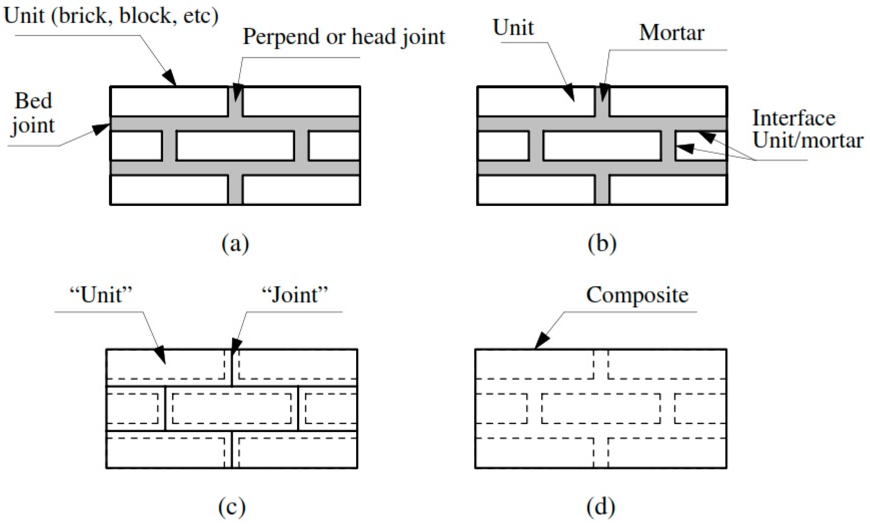
4.2.1. Modeling Masonry as a Three-Phase Material (Detailed Micro-Modeling Approach)
4.2.2. Modeling Masonry as a Two-Phase Material (Simplified Micro-Modeling Approach)
4.2.3. Modeling Masonry as a One-Phase Material (Macro-Modeling Approach)
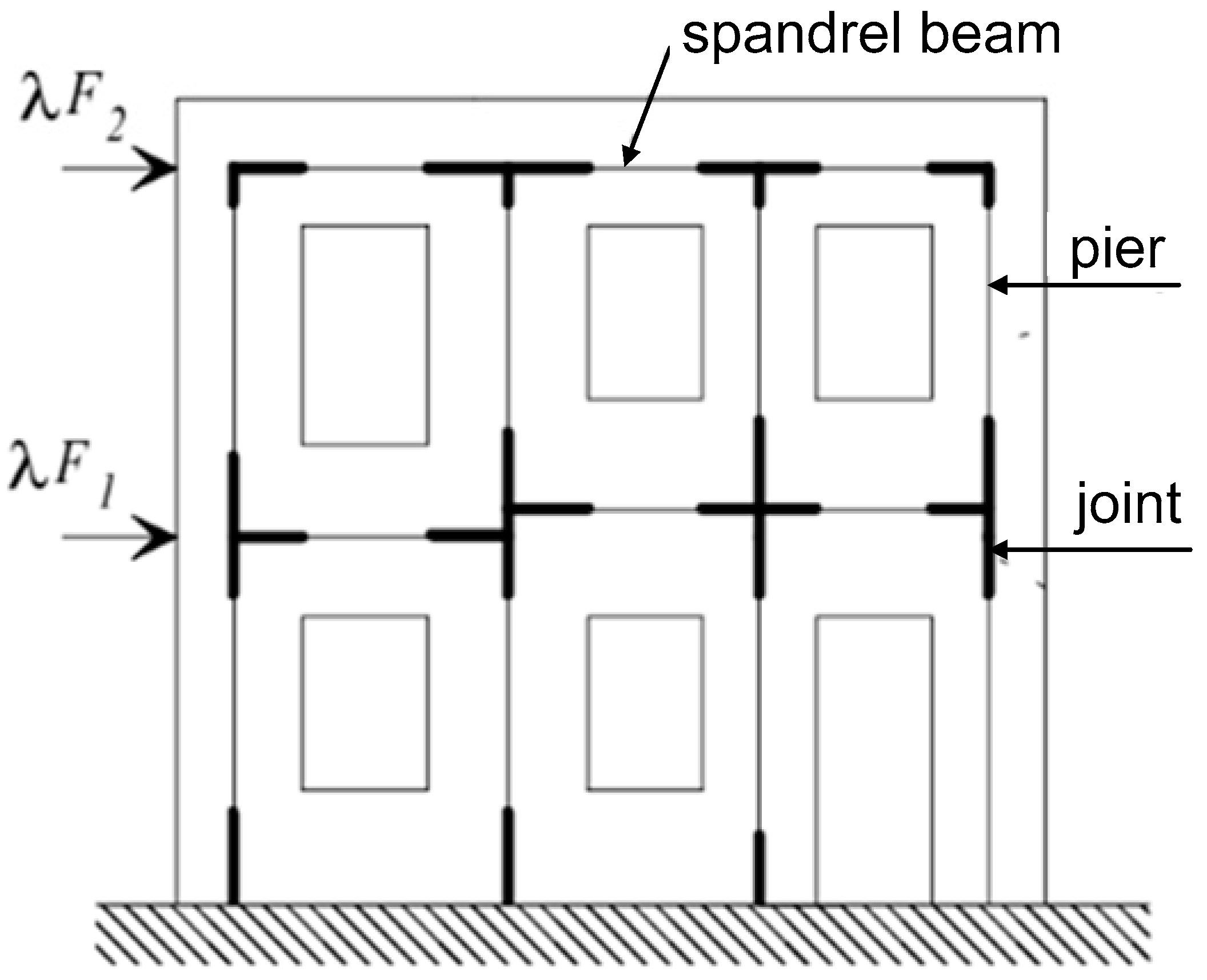
4.2.4. Modeling Masonry Using Equivalent Frame Method
4.3. Anisotropic Finite Element Macro-Model
4.3.1. Displacement Functions
4.3.2. Strain (Total)
4.3.3. The Stiffness Matrix
4.4. Failure Criteria
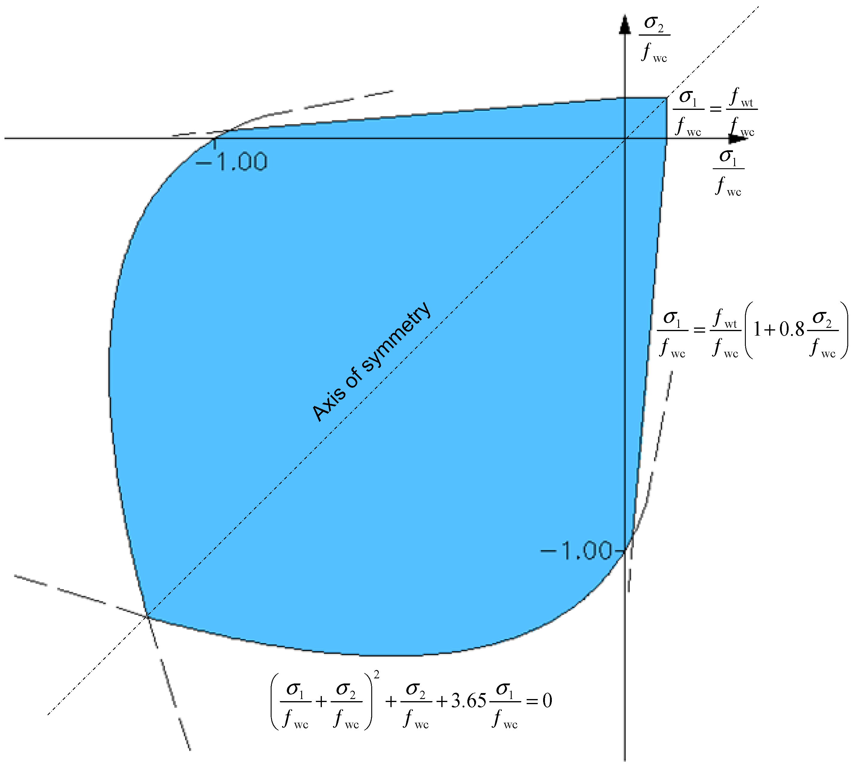
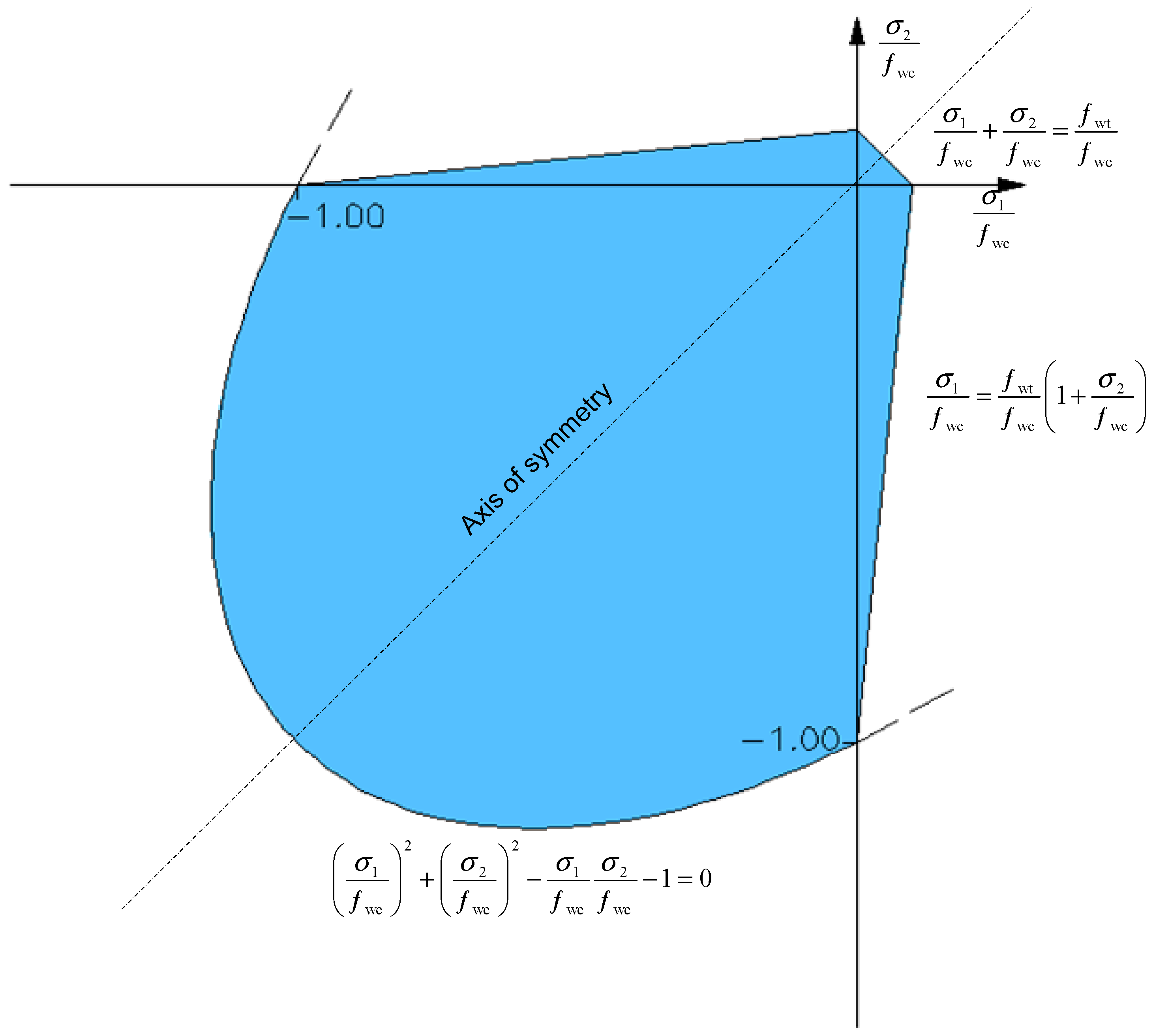
4.4.1. Semi-Empirical Isotropic Failure Criteria
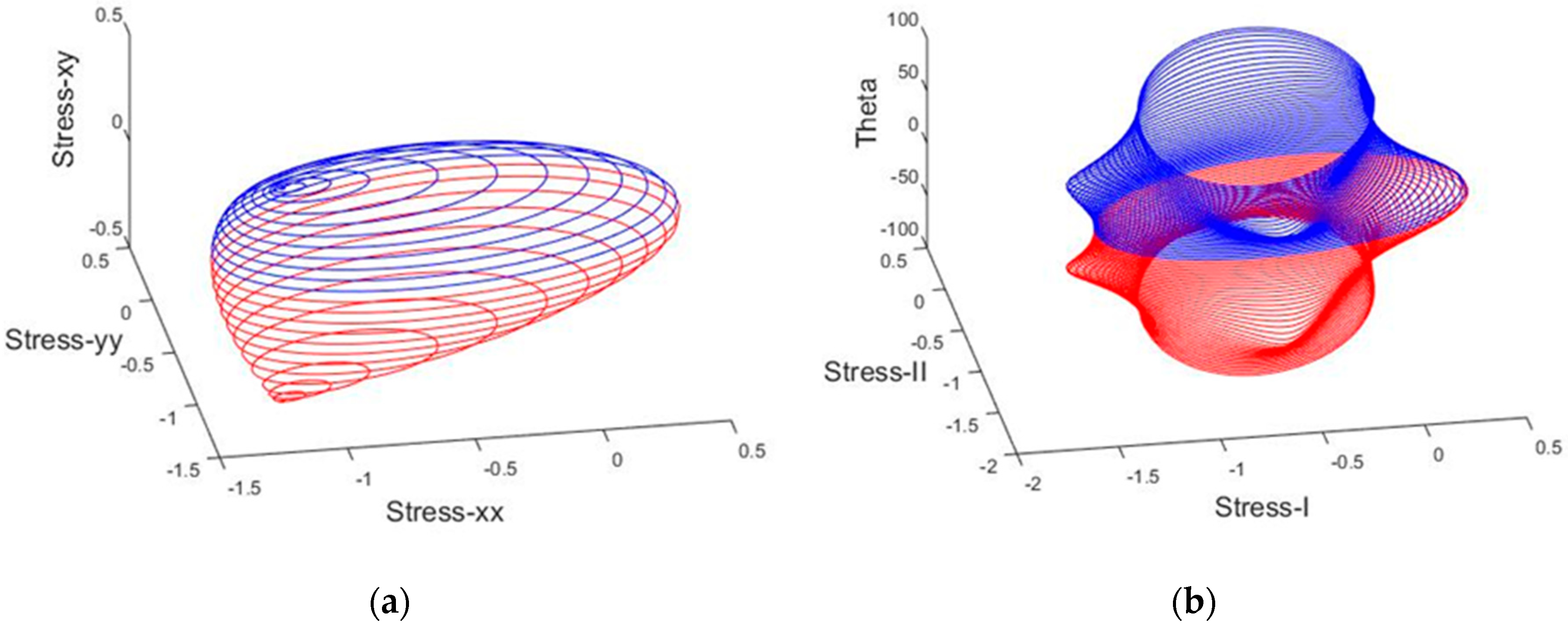
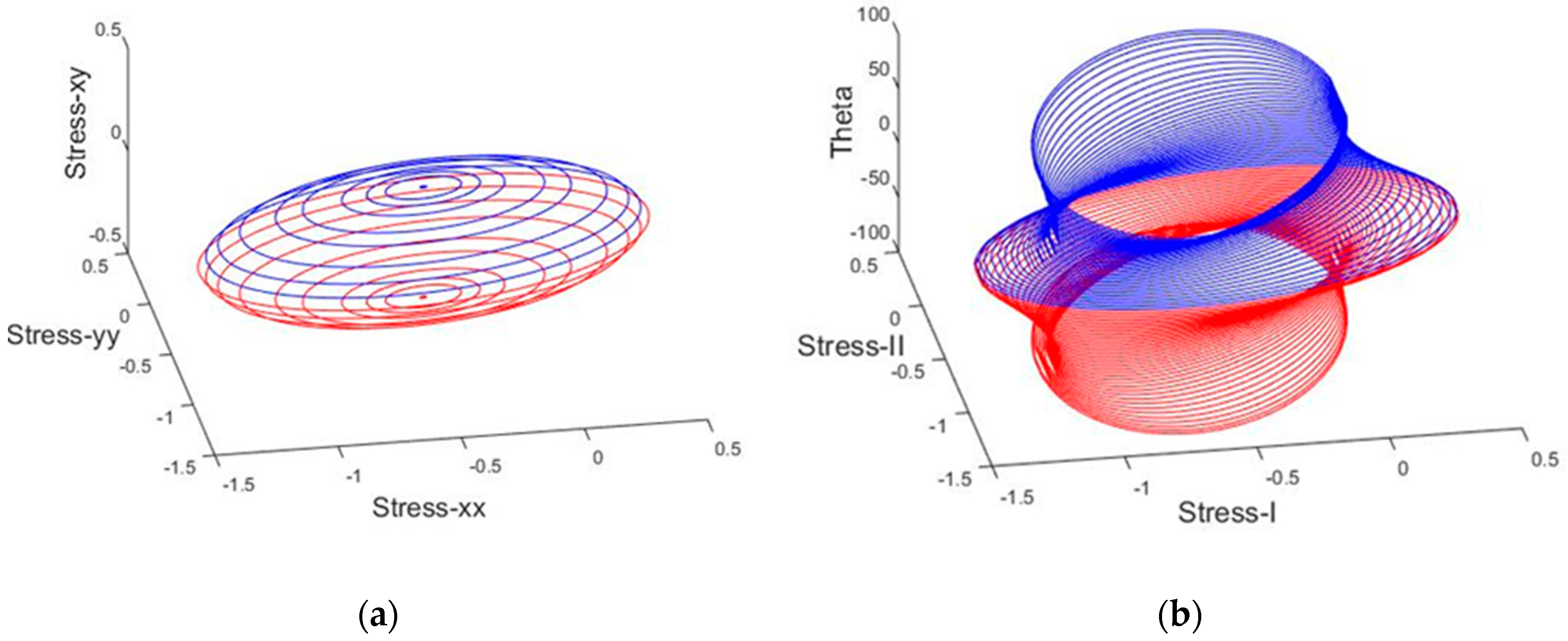
4.4.2. Cubic Tensor Polynomial
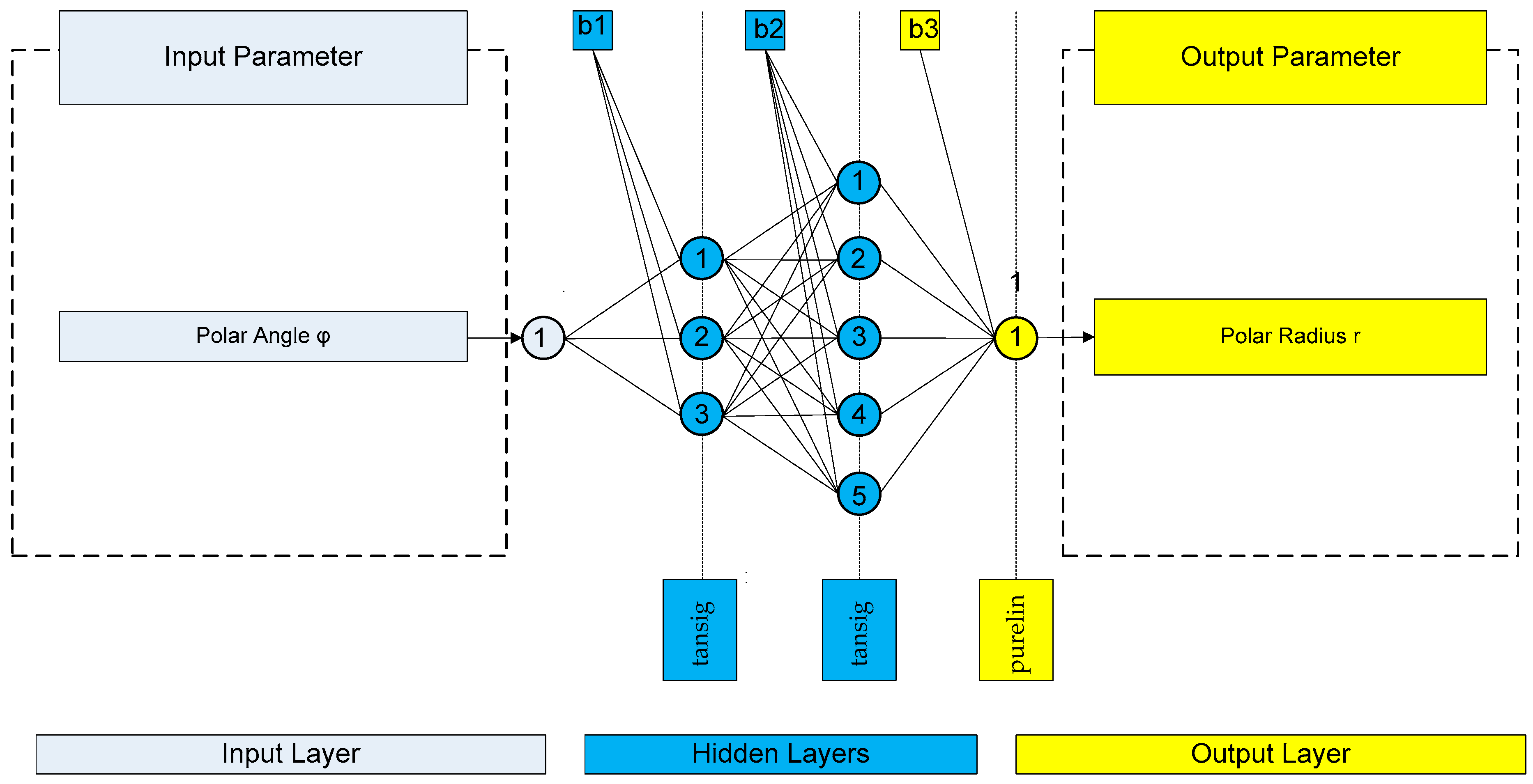
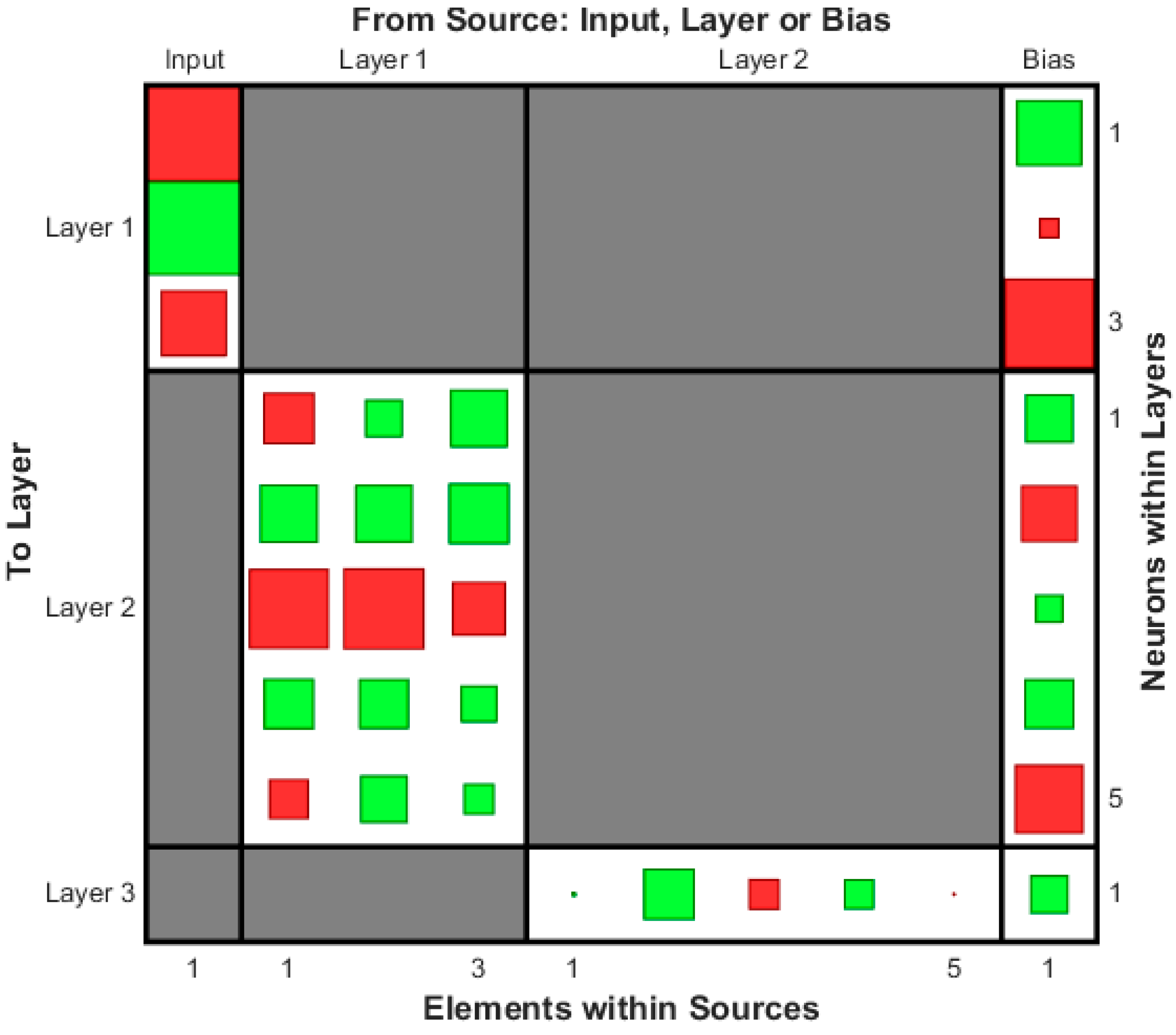
4.4.3. Failure Criterion Based on Artificial Neural Networks
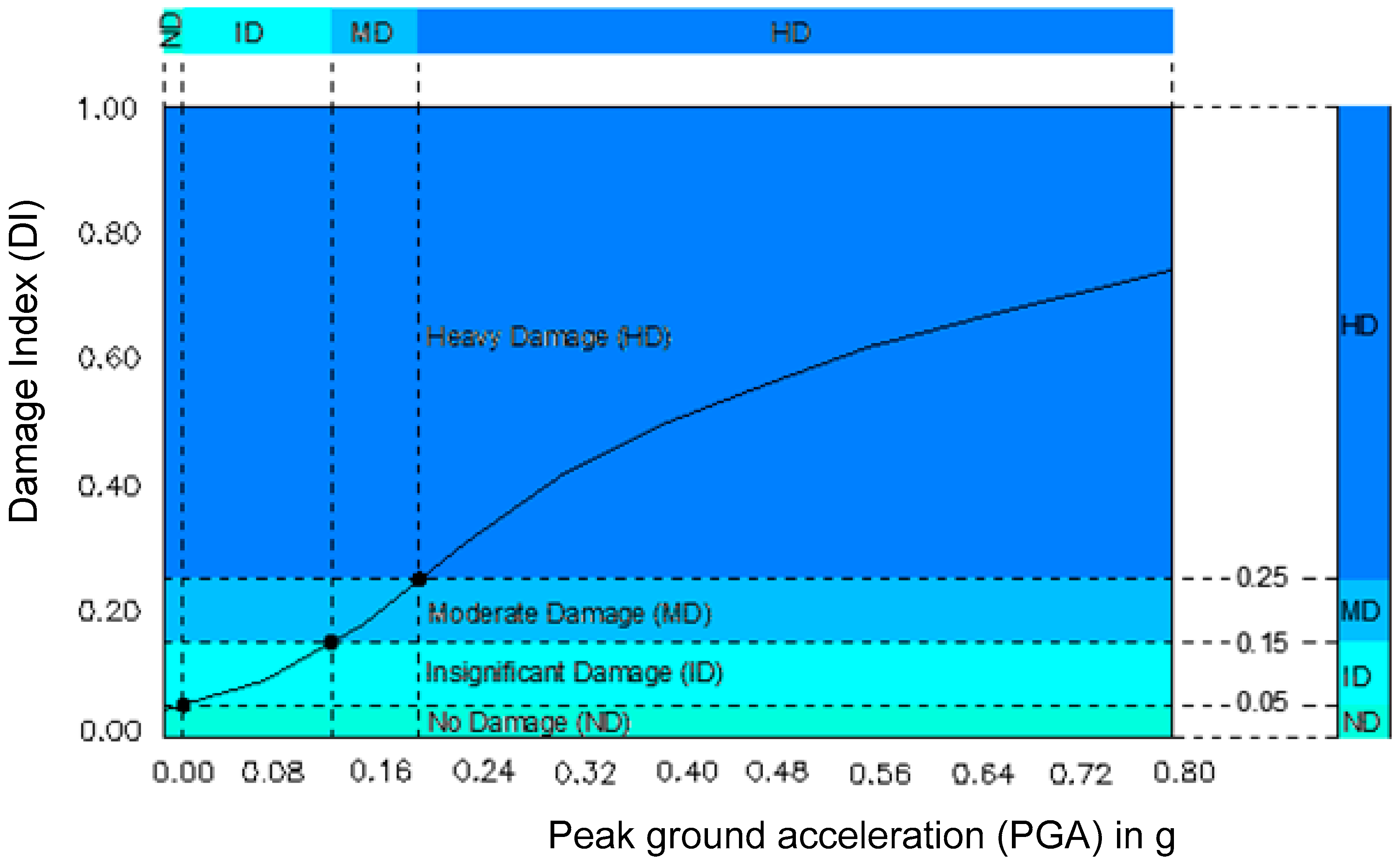
4.5. Damage Index
4.6. Damage States and Structural Performance Levels
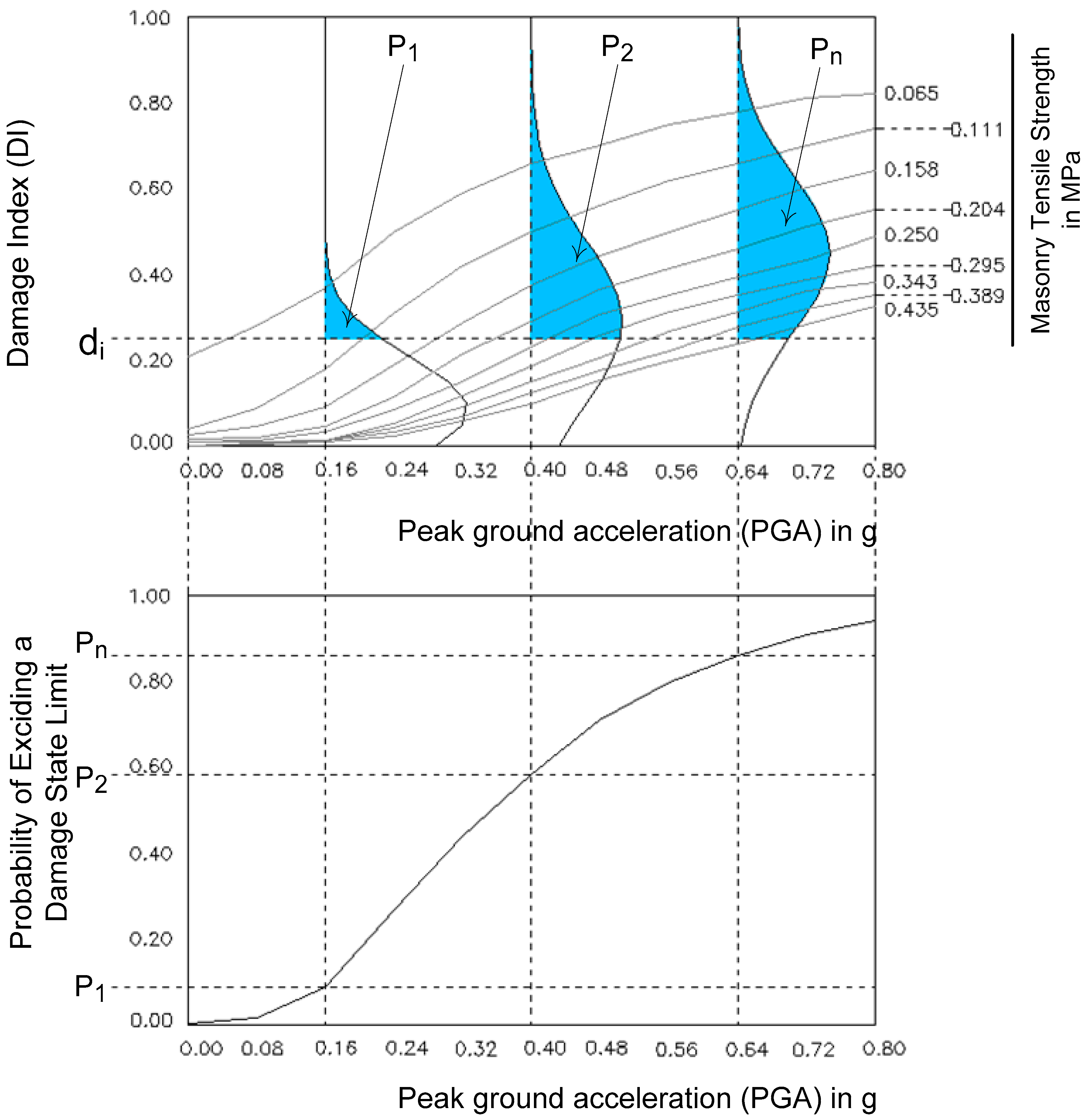
4.7. Fragility Curves
5. Finite Element Code
5.1. Basic Characteristics of Finite Element Code
| clc; clear; eldof = 8; % eldof (=8)the number of dofs per element % Form the steering vector from element’s degrees of freedom eldofs = [1; 2; 5; 6; 7; 8; 10; 11]; %{ % Assemble the global stiffness matrix putting the element stiffness matrix in global system %} for i = 1:eldof if eldofs(i) ~= 0 for j = 1: eldof if eldofs(j) ~= 0 k_glob(eldofs(i),eldofs(j))=k_glob(eldofs(i),eldofs(j))+k_elem_glob(i,j); end end end end |
5.2. Presentation of the Finite Element Code
6. Restoration Aspects
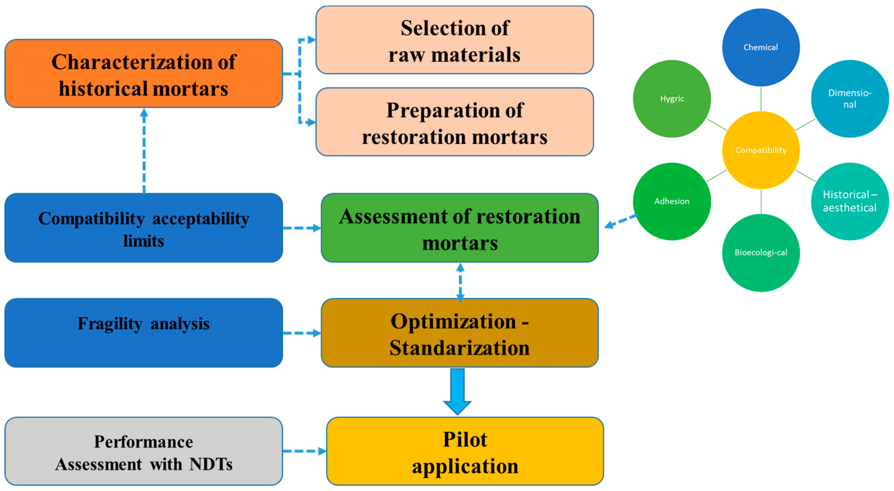
6.1. Historical Mortars as a Basis for the Design of Restoration Mortars
6.2. Historical Mortars
6.3. Restoration Mortars
7. Case Studies
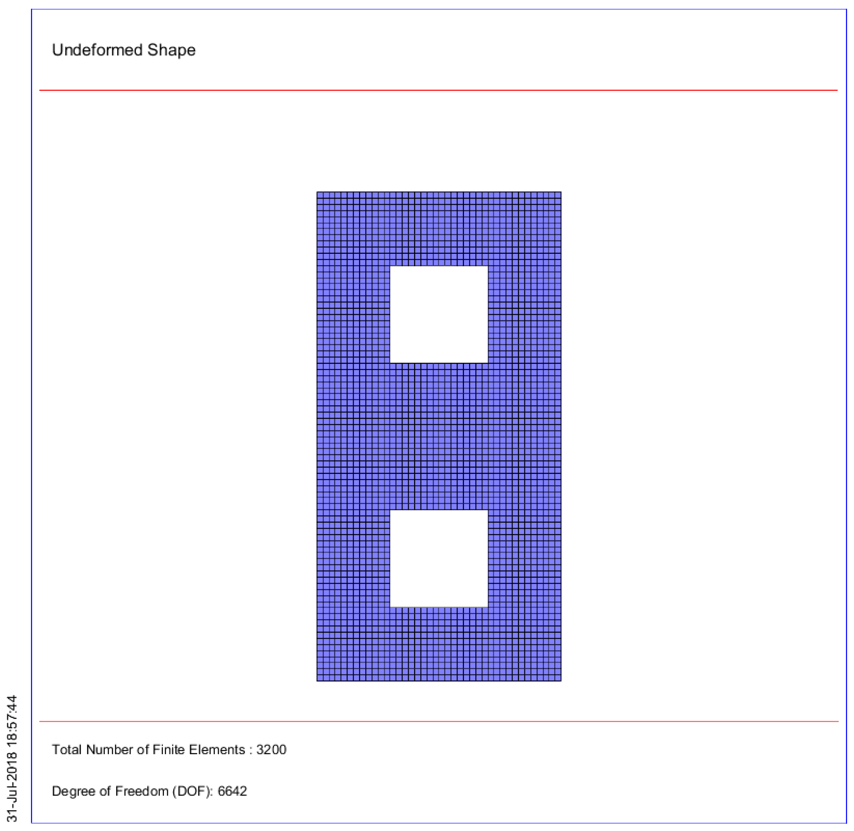
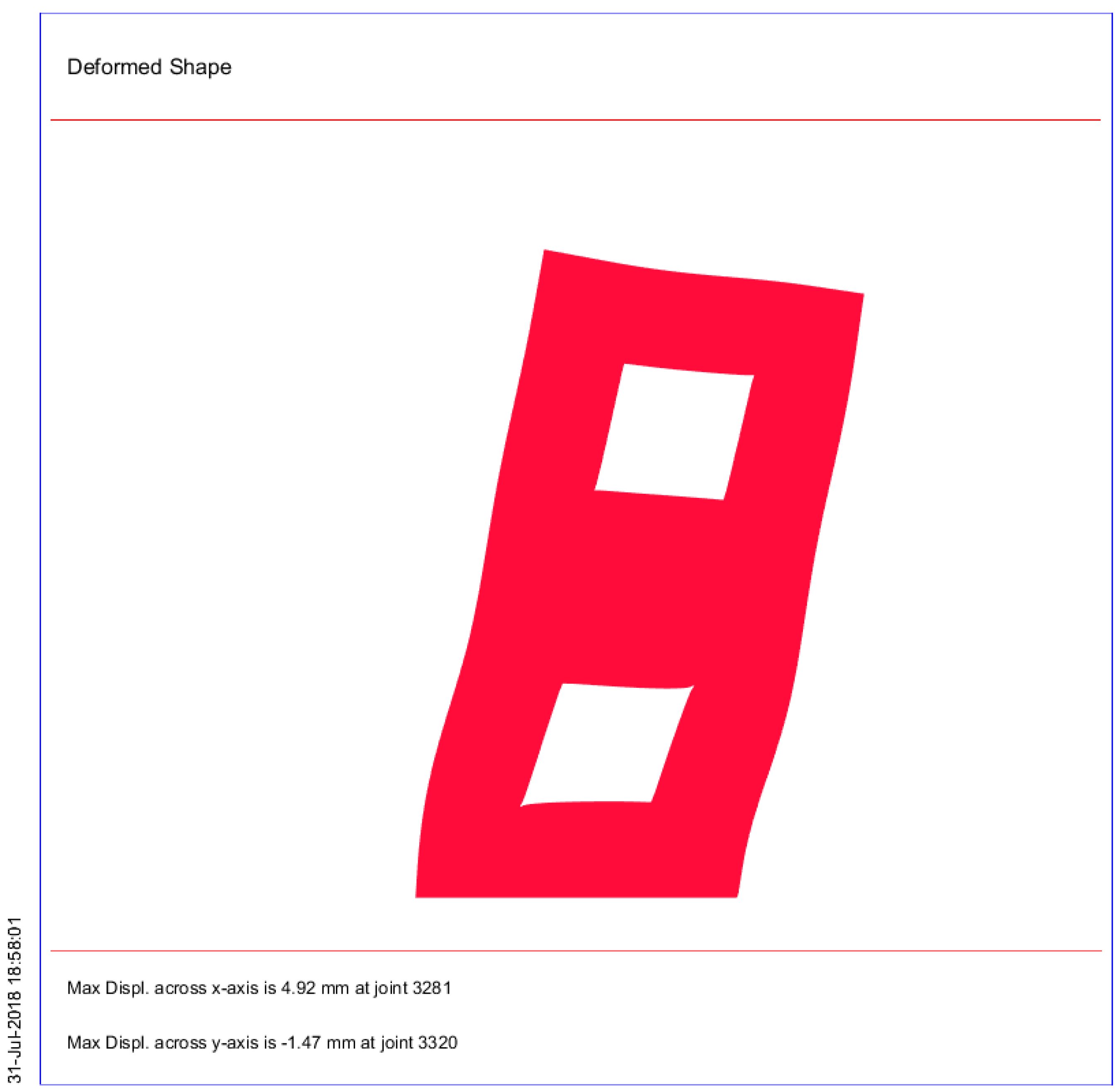
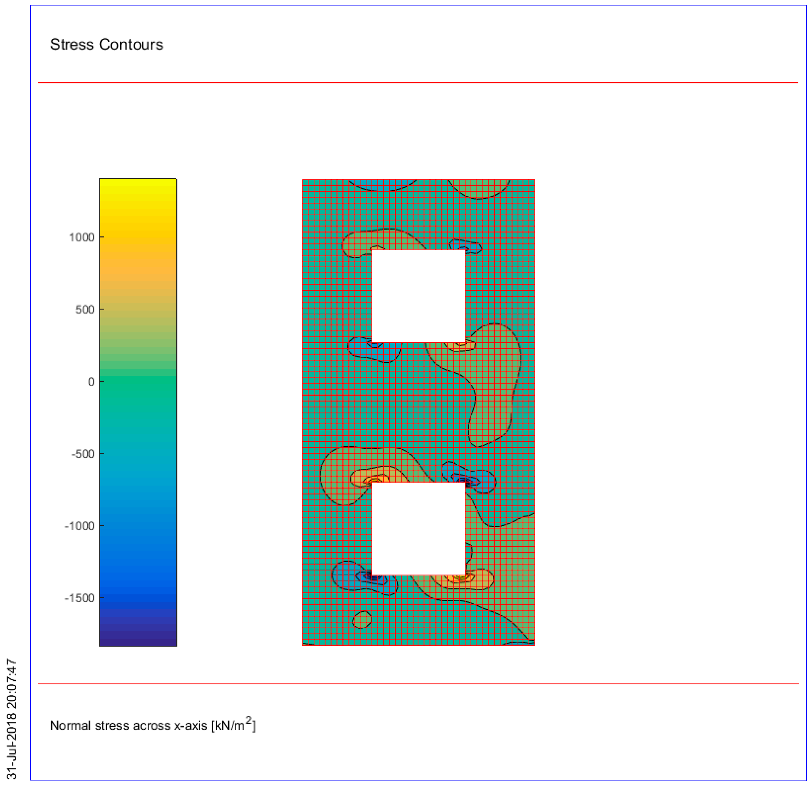
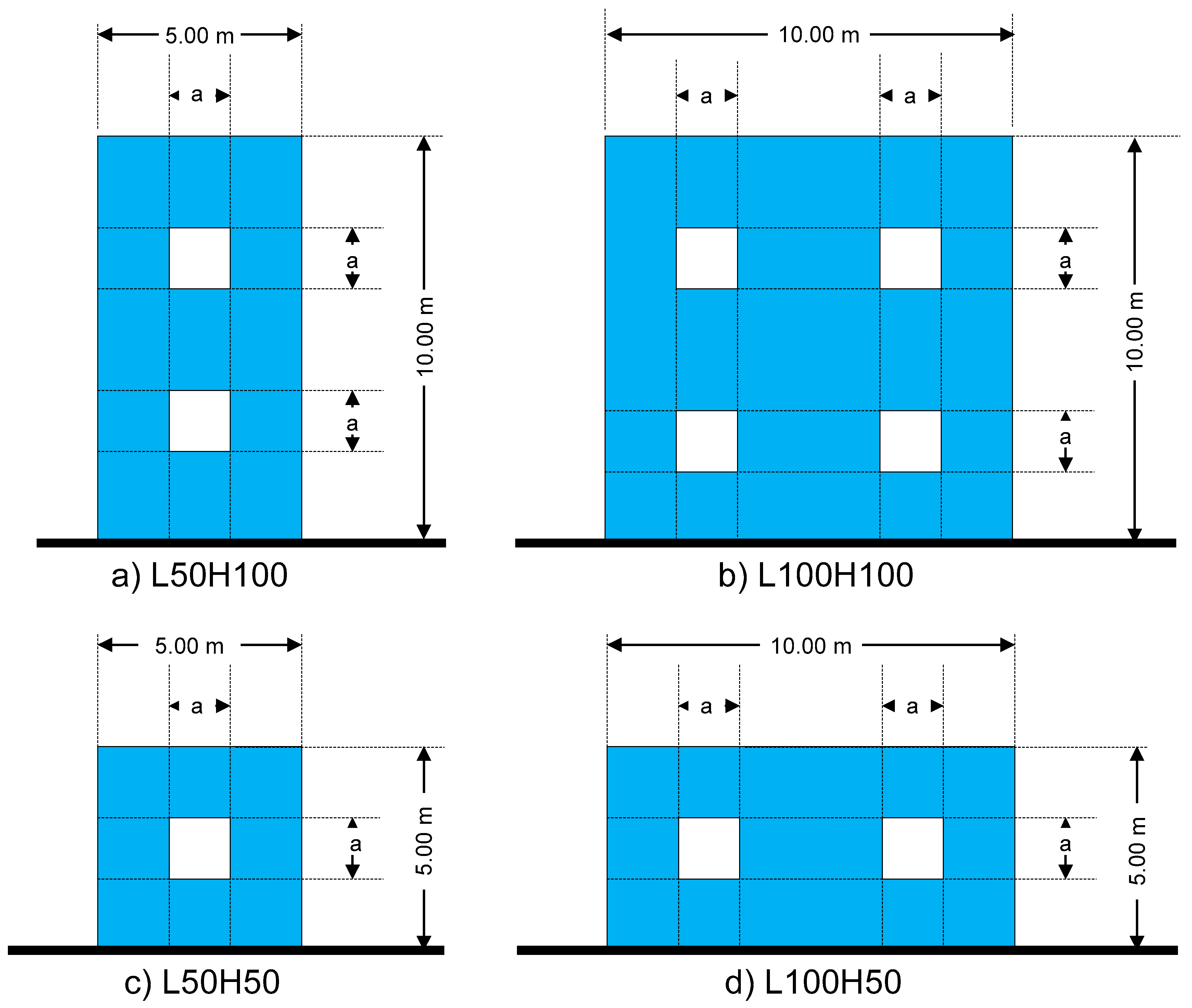
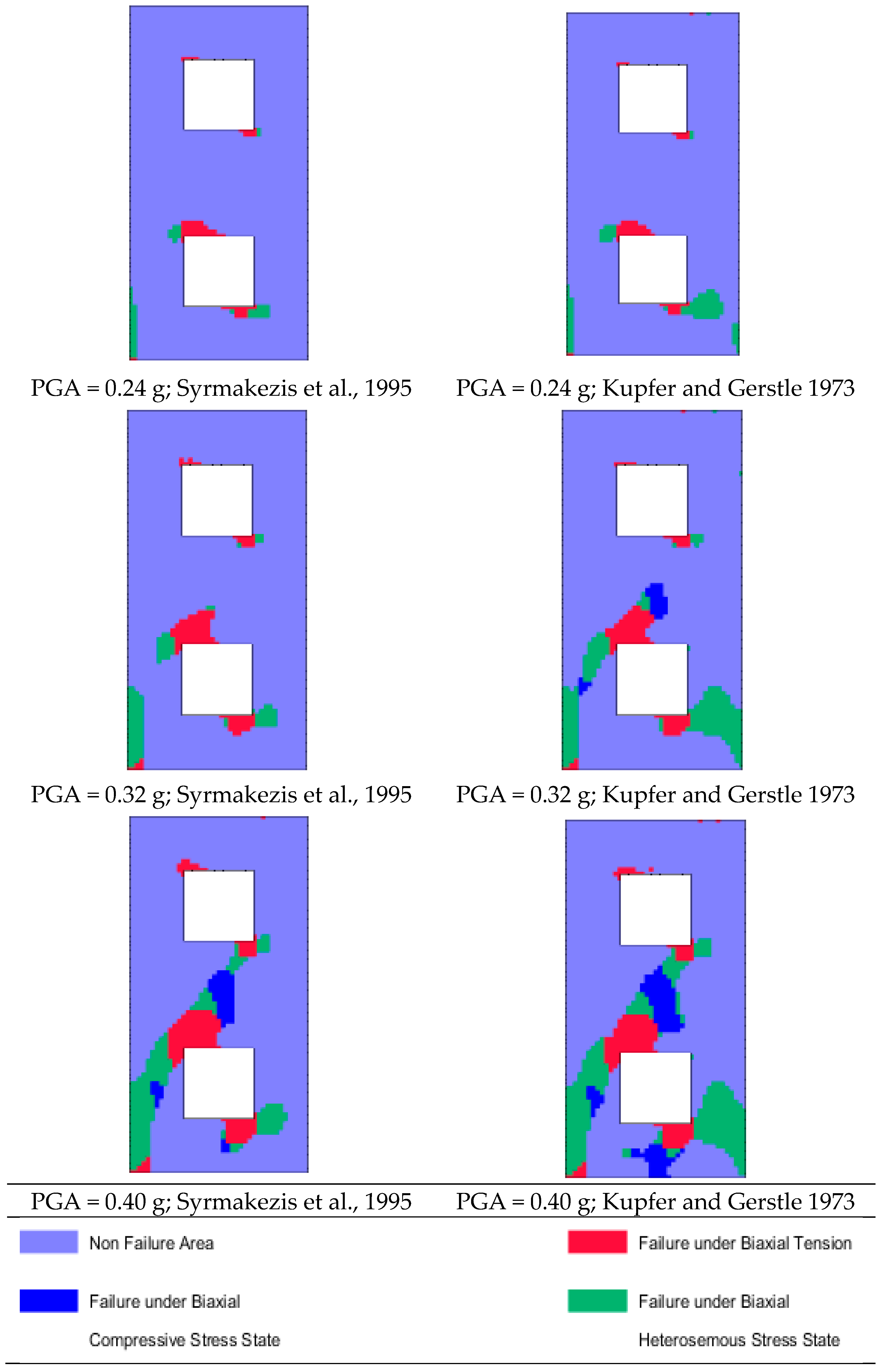
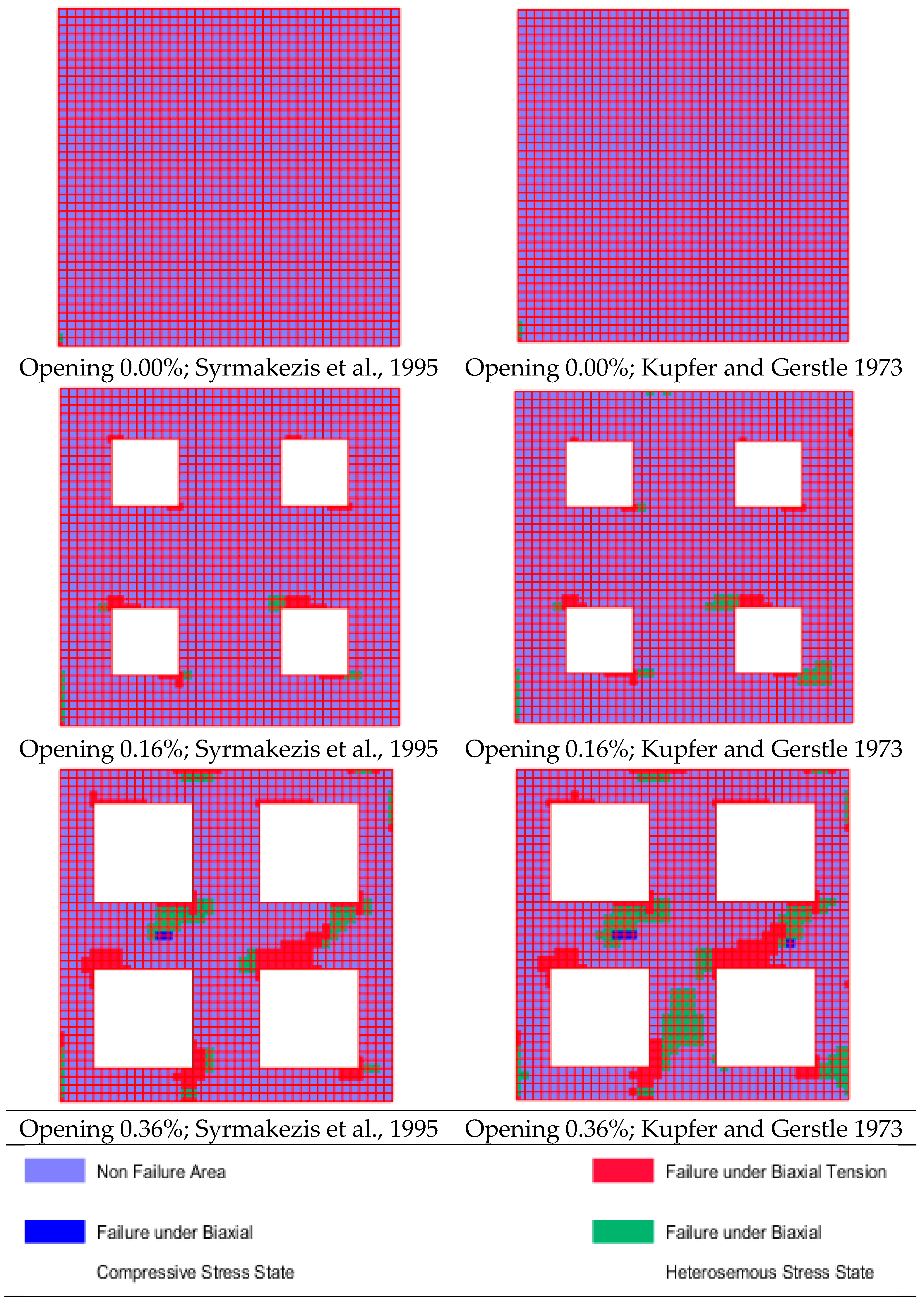
7.1. 2D Masonry Walls
7.2. Monumental Masonry Structures
8. Conclusions
Author Contributions
Funding
Acknowledgments
Conflicts of Interest
Abbreviations
| ANNs | Artificial Neural Networks |
| BPNNs | Back-Propagation Neural Networks |
| CDF | Cumulative Distribution Function |
| DI | Damage Index |
| DOF | Degrees of Freedom |
| DS | Damage State |
| EC2 | Eurocode 2 |
| EC8 | Eurocode 8 |
| FE | Finite element |
| FEM | Finite Element Method |
| HD | Heavy Damage |
| ID | Insignificant Damage |
| IM | Intensity Measure |
| IML | Intensity Measure Level |
| logsig | Log-sigmoid transfer function |
| LN | Lognormal |
| LS | Limit state |
| MAFEA | MAsonry Finite Element Analysis |
| MD | Moderate Damage |
| ND | No Damage |
| PGA | Peak Ground Acceleration |
| Probability Density Function | |
| purelin | Linear transfer function |
| RC | Reinforced Concrete |
| tansig | Hyperbolic Tangent Sigmoid transfer function |
| URM | UnReinforced Masonry |
List of Symbols
| Damaged surface area of the structure | |
| Total surface area of the structure | |
| E | Modulus of elasticity |
| Ex | Modulus of Elasticity across x-axis |
| Ey | Modulus of Elasticity across y-axis |
| Gxy | Shear modulus in the xy plane |
| P(·) | Probability |
| Sa | Spectral acceleration |
| Sa(T) | Spectral acceleration at period T |
| Sd(T) | Spectral displacement at period T |
| SI | Spectrum Intensity |
| Masonry compressive strength | |
| Brick compressive strength | |
| Mortar compressive strength | |
| h | Height of masonry wall |
| t | Thickness of masonry wall |
| tb | Height of brick |
| tm | Thickness of mortar joint |
| Relative volume of unit | |
| Relative volume of mortar |
| β | Ratio of finite element dimensions |
| ν | Poisson’s ratio |
| νxy | Poisson’s ratio in the xy plane |
| νyx | Poisson’s ratio in the yx plane |
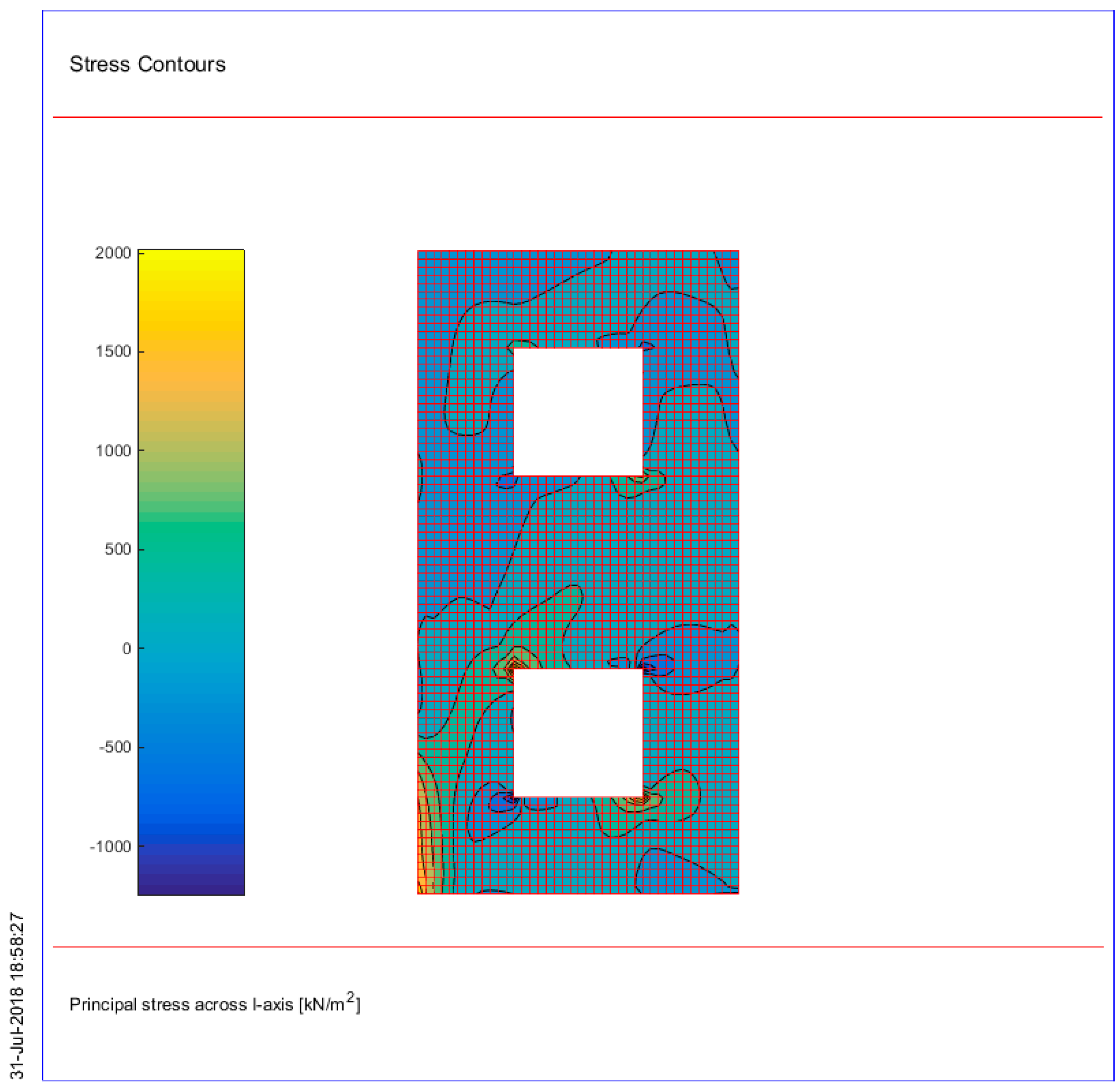
| σI | Principal stress across I-axis |
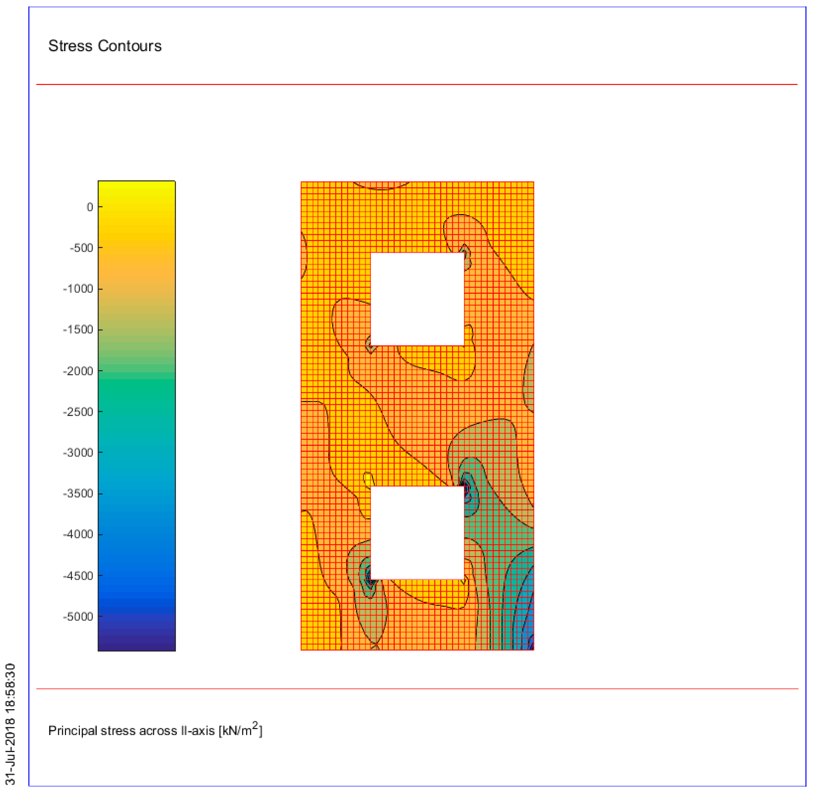
| σII | Principal stress across II-axis. |
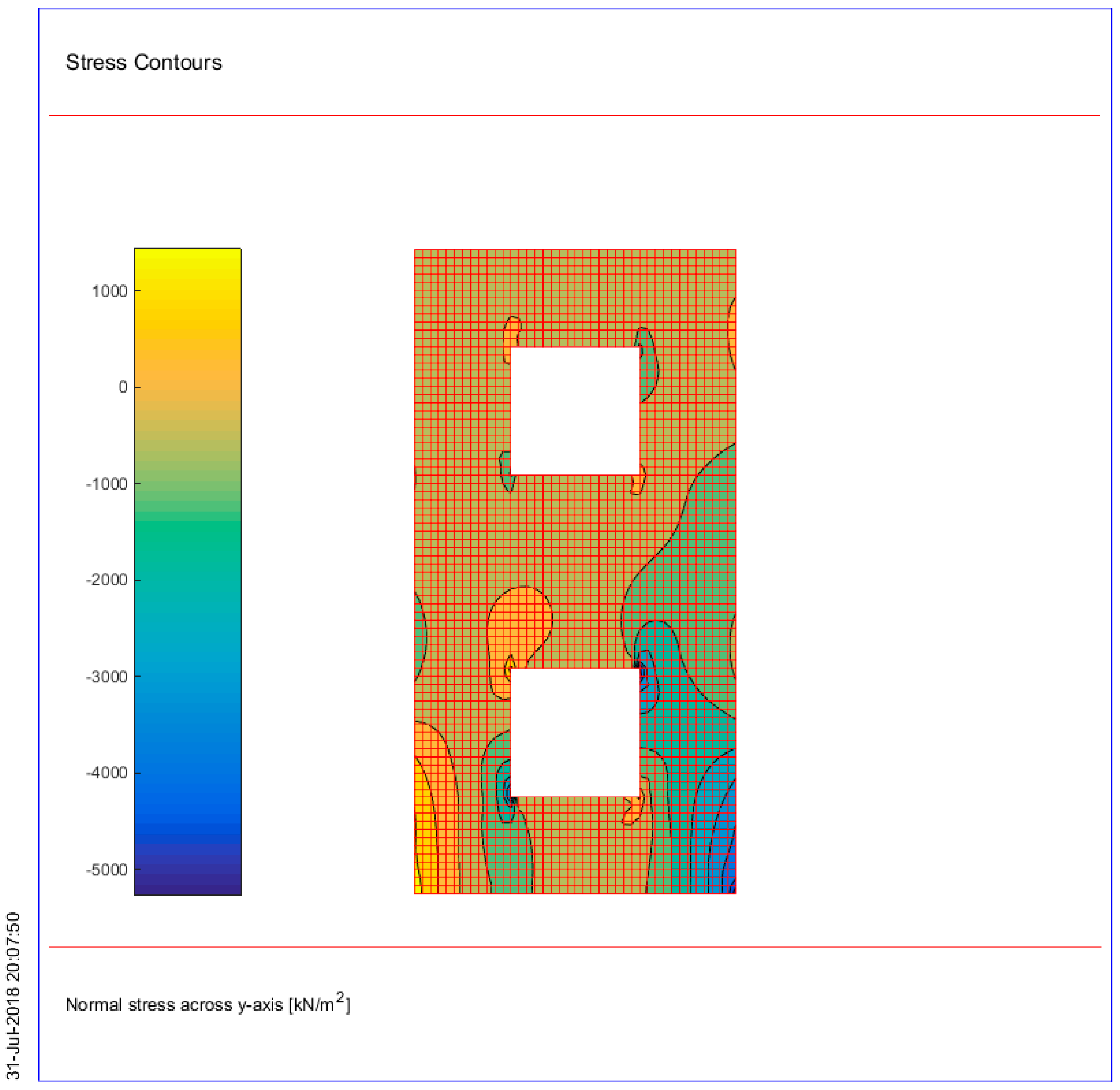
| σx | Normal stress across x-axis |
| σy | Normal stress across y-axis |
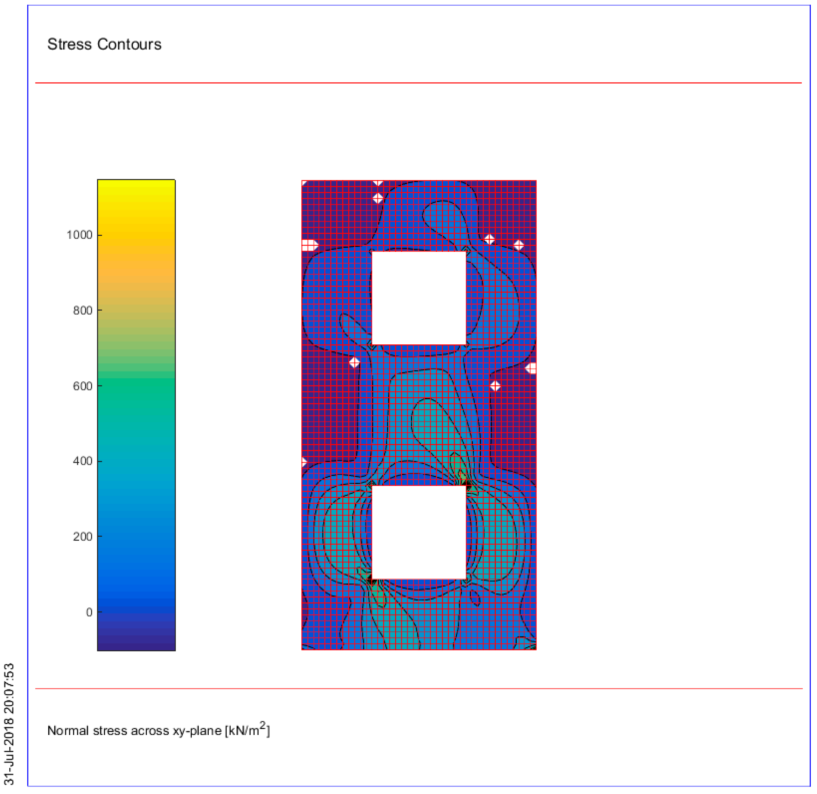
| τ | Shear stress measured in the x-y plane |
Appendix A
References
- Ramos, L.; Lourenço, P.B. Modeling and vulnerability of historical city centers in seismic areas: A case study in Lisbon. Eng. Struct. 2004, 26, 1295–1310. [Google Scholar] [CrossRef]
- Lourenço, P.B.; Roque, J.A. Simplified indexes for the seismic vulnerability of ancient masonry buildings. Constr. Build. Mater. 2006, 20, 200–208. [Google Scholar] [CrossRef] [Green Version]
- Lagomarsino, S.; Resemini, S. The assessment of damage limitation state in the seismic analysis of monumental buildings. Earthq. Spectra 2009, 25, 323–346. [Google Scholar] [CrossRef]
- Milani, G.; Venturini, G. Automatic fragility curve evaluation of masonry churches accounting for partial collapses by means of 3D FE homogenized limit analysis. Comput. Struct. 2011, 89, 1628–1648. [Google Scholar] [CrossRef]
- ICOMOS1931. The Athens Charter for the Restoration of Historic Monuments. In Proceedings of the First International Congress of Architects and Technicians of Historic Monuments, Athens, Greece, 1931; Available online: http://www.icomos.org/athens_charter.html (accessed on 10 December 2018).
- ICOMOS1964. The Venice Charter for the Restoration of Historic Monuments. In Proceedings of the Second International Congress of Architects and Technicians of Historic Monuments, Venice, Italy, 1964; Available online: http://www.international.icomos.org/charters/venice_e.htm (accessed on 10 December 2018).
- Morton, B.; Hume, G.L. The Secretary of the Interior’s Standards for Historic Preservation Projects with Guidelines for Applying the Standards; United States Department of the Interior, Heritage Conservation and Recreation Service: Washington, DC, USA, 1979.
- Syrmakezis, C.A.; Chronopoulos, M.P.; Sophocleous, A.A.; Asteris, P.G. Structural analysis methodology for historical buildings. Archit. Stud. Mater. Anal. 1995, 1, 373–382. [Google Scholar]
- Asteris, P.G.; Giannopoulos, I.P. Vulnerability and Restoration Assessment of Masonry Structural Systems. Electron. J. Struct. Eng. 2012, 12, 82–93. [Google Scholar]
- D’Ayala, D.; Speranza, E. An integrated procedure for the assessment of the seismic vulnerability of historic buildings. In Proceedings of the 12th European Conference on Earthquake Engineering, London, UK, 9–13 September 2002. [Google Scholar]
- D’Ayala, D.; Speranza, E. Definition of collapse mechanisms and seismic vulnerability of masonry structures. Earthq. Spectra 2003, 19, 479–509. [Google Scholar] [CrossRef]
- D’Ayala, D.F.; Paganoni, S. Assessment and analysis of damage in L’Aquila historic city centre after 6th April 2009. Bull. Earthq. Eng. 2011, 9, 81–104. [Google Scholar] [CrossRef]
- D’Ayala, D. Force and Displacement Based Vulnerability Assessment for Traditional Buildings. Bull. Earthq. Eng. 2005, 3, 235–265. [Google Scholar] [CrossRef]
- Erberik, M.A. Generation of fragility curves for Turkish masonry buildings considering in-plane failure modes. Earthq. Eng. Struct. Dyn. 2008, 37, 387–405. [Google Scholar] [CrossRef]
- Erberik, M.A. Seismic Risk Assessment of Masonry Buildings in Istanbul for Effective Risk Mitigation. Earthq. Spectra 2010, 26, 967–982. [Google Scholar] [CrossRef]
- Bartoli, G.; Betti, M.; Vignoli, A. A numerical study on seismic risk assessment of historic masonry towers: A case study in San Gimignano. Bull. Earthq. Eng. 2016, 14, 1475–1518. [Google Scholar] [CrossRef]
- Betti, M.; Drosopoulos, G.A.; Stavroulakis, G.E. Two non-linear finite element models developed for the assessment of failure of masonry arches. Comptes Rendus Mec. 2008, 336, 42–53. [Google Scholar] [CrossRef]
- Castori, G.; Borri, A.; De Maria, A.; Corradi, M.; Sisti, R. Seismic vulnerability assessment of a monumental masonry building. Eng. Struct. 2017, 136, 454–465. [Google Scholar] [CrossRef] [Green Version]
- Corradi, M.; Borri, A.; Castori, G.; Coventry, K. Experimental analysis of dynamic effects of FRP reinforced masonry vaults. Materials 2015, 8, 8059–8071. [Google Scholar] [CrossRef] [PubMed]
- Bartoli, G.; Betti, M.; Giordano, S. In situ static and dynamic investigations on the “Torre Grossa” masonry tower. Eng. Struct. 2013, 52, 718–733. [Google Scholar] [CrossRef]
- Lourenço, P.B.; Karanikoloudis, G.; Greco, F. In situ testing and modeling of cultural heritage buildings in Peru, Structural Analysis of Historical Constructions: Anamnesis, diagnosis, therapy, controls. In Proceedings of the 10th International Conference on Structural Analysis of Historical Constructions, SAHC, Leuven, Belgium, 13–15 September 2016; pp. 850–857. [Google Scholar]
- Lourenço, P.B. Technologies for seismic retrofitting and strengthening of earthen and masonry structures: Assessment and application. Geotech. Geol. Earthq. Eng. 2018, 46, 501–518. [Google Scholar]
- Karanikoloudis, G.; Lourenço, P.B. Structural assessment and seismic vulnerability of earthen historic structures. Application of sophisticated numerical and simple analytical models. Eng. Struct. 2018, 160, 488–509. [Google Scholar] [CrossRef]
- Tiedeman, H. A statistical evaluation of the importance of nonstructural damage to buildings. In Proceedings of the 7th World Conference on Earthquake Engineering, International Association of Earthquake Engineering (IAEE), Tokyo, Japan, 8–13 September 1980; Volume 6, pp. 617–624. [Google Scholar]
- Syrmakezis, C.A.; Asteris, P.G.; Sophocleous, A.A. Earthquake resistant design of masonry tower structures. In Proceedings of the Fifth International Conference on Structural Studies of Historical Buildings, San Sebastian, Spain, 25–27 June 1997; Volume 3, pp. 377–386. [Google Scholar]
- Binda, L.; Saisi, A.; Tiraboschi, C. Investigation procedures for the diagnosis of historic masonries. Constr. Build. Mater. 2000, 14, 199–233. [Google Scholar] [CrossRef]
- Lourenço, P.B. Recommendations for restoration of ancient buildings and the survival of a masonry chimney. Constr. Build. Mater. 2006, 20, 239–251. [Google Scholar] [CrossRef] [Green Version]
- Fang, D.L.; Napolitano, R.K.; Michiels, T.L.; Adriaenssens, S.M. Assessing the stability of unreinforced masonry arches and vaults: Acomparison of analytical and numerical strategies. Int. J. Archit. Herit. 2018. [Google Scholar] [CrossRef]
- Asteris, P.G. On the structural analysis and seismic protection of historical masonry structures. Open Constr. Build. Technol. J. 2008, 2, 124–133. [Google Scholar] [CrossRef]
- Onaka, T. A study of the documentation process for conservation of architectural heritage sites: Illustrated by examples from Egypt and Belgium. In Proceedings of the 22nd CIPA symposium, Kyoto, Japan, 11–15 October 2009. [Google Scholar]
- Syrmakezis, C.; Sophocleous, A.; Asteris, P.; Liolios, A. Earthquake resistant design of masonry structural systems. In Proceedings of the Earthquake Resistant Engineering Structures, ERES96, Thessaloniki, Greece, 30 October–1 November 1996; Volume 2, pp. 717–726. [Google Scholar]
- Chronopoulos, P.M.; Zigouris, N.; Asteris, P.G. Investigation/Documentation and Aspects of Seismic Assesment and Redesign of Traditional Masonry Buildings in Greece. In Proceedings of the 5th European Conference on Structural Control (EACS 2012 ), Genoa, Italy, 18–20 June 2012. [Google Scholar]
- Tassios, T.P. Seismic engineering of monuments. Bull. Earthq. Eng. 2010, 8, 1231–1265. [Google Scholar] [CrossRef]
- Chrysostomou, C.Z.; Kyriakides, N.; Roussis, P.C.; Asteris, P.G. Emerging technologies and materials for the seismic protection of cultural heritage. In Handbook of Research on Seismic Assessment and Rehabilitation of Historic Structures; Asteris, P.G., Plevris, V., Eds.; IGI Global: Hershey, PA, USA, 2015. [Google Scholar]
- Asteris, P.G.; Tzamtzis, A.D.; Vouthouni, P.P.; Sophianopoulos, D.S. Earthquake Resistant Design and Rehabilitation of Masonry Historical Structures. Pract. Period. Struct. Des. Constr. 2005, 10, 49–55. [Google Scholar] [CrossRef]
- Blasi, C.; Coïsson, E. The importance of historical documents for the study of stability of the, ancient buildings: The French Panthéon case study. Asian J. Civ. Eng. 2006, 7, 359–368. [Google Scholar]
- Blasi, C.; Coïsson, E.; Iori, I. The fractures of the French Panthéon: Survey and structural analysis. Eng. Fract. Mech. 2008, 75, 379–388. [Google Scholar] [CrossRef]
- Asteris, P.G.; Chronopoulos, M.P.; Chrysostomou, C.Z.; Varum, H.; Plevris, V.; Kyriakides, N.; Silva, V. Seismic vulnerability assessment of historical masonry structural systems. Eng. Struct. 2014, 62–63, 118–134. [Google Scholar] [CrossRef]
- Bartoli, G.; Betti, M.; Blasi, C.; Ottoni, F.; Coli, M.; Marchetti, E.; Ripepe, M. Synergistic and Interdisciplinary Approaches for the Conservation of Monumental Heritage: Cupola of Santa Maria del Fiore in Florence, Italy. J. Perform. Constr. Facil. 2016, 30, 04015091. [Google Scholar] [CrossRef]
- Asteris, P.G.; Sarhosis, V.; Mohebkhah, A.; Plevris, V.; Papaloizou, L.; Komodromos, P.; Lemos, J.V. Numerical Modeling of Historic Masonry Structures. In Handbook of Research on Seismic Assessment and Rehabilitation of Historic Structures; Asteris, P.G., Plevris, V., Eds.; IGI Global: Hershey, PA, USA, 2015. [Google Scholar]
- Triantafillou, T.C.; Fardis, M.N. Strengthening of historic masonry structures with composite materials. Mater. Struct. Mater. Et Constr. 1997, 30, 486–496. [Google Scholar] [CrossRef]
- Asteris, P.G.; Douvika, M.; Karakitsios, P.; Moundoulas, P.; Apostolopoulou, M.; Moropoulou, A. A Stochastic Computational Framework for the Seismic Assessment of Monumental Masonry Structures. In Proceedings of the 5th International Conference on Integrity, Reliability and Failure, Faculty of Engineering, Porto, Portugal, 24–28 July 2016. [Google Scholar]
- Mistler, M.; Butenweg, C.; Meskouris, K. Modelling methods of historic masonry buildings under seismic excitation. J. Seismol. 2006, 10, 497–510. [Google Scholar] [CrossRef]
- Asteris, P.G.; Plevris, V. Handbook of Research on Seismic Assessment and Rehabilitation of Historic Structures; IGI Global: Hershey, PA, USA, 2015; pp. 1–867. [Google Scholar]
- Apostolopoulou, M.; Aggelakopoulou, E.; Siouta, L.; Bakolas, A.; Douvika, M.; Asteris, P.G.; Moropoulou, A. A methodological approach for the selection of compatible and performable restoration mortars in seismic hazard areas. Constr. Build. Mater. 2017, 155, 1–14. [Google Scholar] [CrossRef]
- Skentou, A.; Douvika, M.G.; Argyropoulos, I.; Apostolopoulou, M.; Moropoulou, A.; Asteris, P.G. Assessment of Masonry Structures Based on Analytical Damage Indices. In Proceedings of the 1st International Conference TMM_CH, Transdisciplinary Multispectral Modelling and Cooperation for the Preservation of Cultural Heritage, Athens, Greece, 10–13 October 2018. [Google Scholar]
- RILEM Technical Committee. Rilem TC 203-RHM: Repair mortars for historic masonry. Testing of hardened mortars, a process of questioning and interpreting. Mater. Struct. 2009, 42, 853–865. [Google Scholar] [CrossRef]
- Barluenga, G.; Estirado, F.; Undurraga, R.; Conde, J.F.; Agua, F.; Villegas, M.Á.; García-Heras, M. Brick masonry identification in a complex historic building, the Main College of the University of Alcalá, Madrid (Spain). Constr. Build. Mater. 2014, 54, 39–46. [Google Scholar] [CrossRef] [Green Version]
- Moropoulou, A.; Zacharias, N.; Delegou, E.T.; Apostolopoulou, M.; Palamara, E.; Kolaiti, A. OSL mortar dating to elucidate the construction history of the tomb chamber of the Holy Aedicule of the Holy Sepulchre in Jerusalem. J. Archaeol. Sci. Rep. 2018, 19, 80–91. [Google Scholar] [CrossRef]
- Georgopoulos, A. CIPA’s perspectives on cultural heritage. Commun. Comput. Inf. Sci. 2018, 817, 215–245. [Google Scholar]
- Hatzopoulos, J.N.; Stefanakis, D.; Georgopoulos, A.; Tapinaki, S.; Pantelis, V.; Liritzis, I. Use of various surveying technologies to 3D digital mapping and modelling of cultural heritage structures for maintenance and restoration purposes: The Tholos in Delphi, Greece. Mediterr. Archaeol. Archaeom. 2017, 17, 311–336. [Google Scholar]
- Labropoulos, K.; Moropoulou, A. Ground penetrating radar investigation of the bell tower of the church of the Holy Sepulchre. Constr. Build. Mater. 2013, 47, 689–700. [Google Scholar] [CrossRef]
- Agrafiotis, P.; Lampropoulos, K.; Georgopoulos, A.; Moropoulou, A. 3D modelling the invisible using ground penetrating radar, International Archives of the Photogrammetry. Remote Sens. Spat. Inf. Sci. ISPRS Arch. 2017, 42, 33–37. [Google Scholar]
- Moropoulou, A.; Bakolas, A.; Bisbikou, K. Physico-chemical adhesion and cohesion bonds in joint mortars imparting durability to the historic structures. Constr. Build. Mater. 2000, 14, 35–46. [Google Scholar] [CrossRef]
- Bruno, P.; Calabrese, D.; Di Pierro, M.; Genga, A.; Laganara, C.; Manigrassi, D.A.P.; Traini, A.; Ubbrìaco, P. Chemical–physical and mineralogical investigation on ancient mortars from the archaeological site of Monte Sannace (Bari—Southern Italy). Thermochim. Acta 2004, 418, 131–141. [Google Scholar] [CrossRef]
- Moropoulou, A.; Bakolas, A.; Bisbikou, K. Investigation of the technology of historic mortars. J. Cult. Herit. 2000, 1, 45–58. [Google Scholar] [CrossRef]
- de Lorenzi Pezzolo, A.; Colombi, M.; Mazzocchin, G.A. Where did Roman masons get their material from? A preliminary DRIFTS/PCA investigation on mortar aggregates from X Regio buildings in the Veneto area (NE Italy) and their potential sources. Environ. Sci. Pollut. Res. 2018. [Google Scholar] [CrossRef] [PubMed]
- Middendorf, B.; Hughes, J.J.; Callebaut, K.; Baronio, G.; Papayianni, I. Investigative methods for the characterisation of historic mortars—Part 1: Mineralogical characterization. Mater. Struct. Mater. Et Constr. 2005, 38, 761–769. [Google Scholar] [CrossRef]
- Middendorf, B.; Hughes, J.J.; Callebaut, K.; Baronio, G.; Papayianni, I. Investigative methods for the characterisation of historic mortars—Part 2: Chemical characterization. Mater. Struct. Mater. Et Constr. 2005, 38, 771–780. [Google Scholar] [CrossRef]
- Moropoulou, A.; Bakolas, A.; Bisbikou, K. Characterization of ancient, byzantine and later historic mortars by thermal and X-ray diffraction techniques. Thermochim. Acta 1995, 269–270, 779–795. [Google Scholar] [CrossRef]
- Moropoulou, A.; Bakolas, A.; Anagnostopoulou, S. Composite materials in ancient structures. Cem. Concr. Compos. 2005, 27, 295–300. [Google Scholar] [CrossRef]
- Ingo, G.M.; Fragalà, I.; Bultrini, G.; De Caro, T.; Riccucci, C.; Chiozzini, G. Thermal and microchemical investigation of Phoenician–Punic mortars used for lining cisterns at Tharros (western Sardinia, Italy). Thermochim. Acta 2004, 418, 53–60. [Google Scholar] [CrossRef]
- Maravelaki-Kalaitzaki, P.; Bakolas, A.; Moropoulou, A. Physico-chemical study of Cretan ancient mortars. Cem. Concr. Res. 2003, 33, 651–661. [Google Scholar] [CrossRef]
- Palomo, A.; Blanco-Varela, M.T.; Martinez-Ramirez, S.; Puertas, F.; Fortes, C. Historic Mortars: Characterization and Durability, New Tendencies for Research; Eduardo Torroja Institute (CSIC): Madrid, Spain, 2002. [Google Scholar]
- Hughes, J.J.; Groot, C.; van Balen, K.; Simsir, B.B.; Luigia, B.; Elsen, J.; van Hees, R.; von Konow, T.; Lindqvist, J.E.; Maurenbrecher, P.; et al. RILEM TC 203-RHM: Repair mortars for historic masonry. The role of mortar in Masonry: An introduction to requirement for the design of repair mortars. Mater. Struct. 2012, 45, 1287–1294. [Google Scholar] [CrossRef]
- Moropoulou, A.; Bakolas, A.; Moundoulas, P.; Aggelakopoulou, E. Reverse engineering: A proper methodology for compatible restoration mortars. In Proceedings of the Workshop Repair Mortars for Historic Masonry, TC RMH; RILEM: Delft, The Netherlands, 2005. [Google Scholar]
- Moropoulou, A.; Labropoulos, K.; Moundoulas, P.; Bakolas, A. The contribution of historic mortars on the earthquake resistance of Byzantine monuments. In Measuring, Monitoring and Modeling Concrete Properties; Springer: Dordrecht, The Netherlands, 2006; pp. 643–652. [Google Scholar]
- Moropoulou, A.; Bakolas, A.; Moundoulas, P.; Aggelakopoulou, E.; Anagnostopoulou, S. Optimization of compatible restoration mortars for the earthquake protection of Hagia Sophia. J. Cult. Herit. 2013, 14, e147–e152. [Google Scholar] [CrossRef]
- Apostolopoulou, M.; Aggelakopoulou, E.; Bakolas, A.; Moropoulou, A. Compatible Mortars for the Sustainable Conservation of Stone in Masonries. In Advanced Materials for the Conservation of Stone; Springer: Cham, Switzerland, 2018; pp. 97–123. [Google Scholar]
- Apostolopoulou, M.; Delegou, E.T.; Alexakis, E.; Kalofonou, M.; Lampropoulos, K.C.; Aggelakopoulou, E.; Bakolas, A.; Moropoulou, A. Study of the historical mortars of the Holy Aedicule as a basis for the design, application and assessment of repair mortars: A multispectral approach applied on the Holy Aedicule. Constr. Build. Mater. 2018, 181, 618–637. [Google Scholar] [CrossRef]
- Tassios, T.P.; Chronopoulos, M.P. A seismic dimensioning of interventions (repairs/strengthening) on low-strength masonry building. In Proceedings of the Middle East and Mediterranean Regional Conference on Earthen and Low-Strength Masonry Buildings in Seismic Areas, Ankara, Turkey, 31 August–6 September 1986. [Google Scholar]
- Sarhat, S.R.; Sherwood, E.G. The prediction of compressive strength of ungrouted hollow concrete block masonry. Constr. Build. Mater. 2014, 58, 111–121. [Google Scholar] [CrossRef]
- Thaickavil, N.N.; Thomas, J. Behaviour and strength assessment of masonry prisms. Case Stud. Constr. Mater. 2018, 8, 23–38. [Google Scholar] [CrossRef]
- Tassios, T.P. Meccanicadelle Murature; Liguori Editore: Napoli, Italy, 1988. [Google Scholar]
- Garzón-Roca, J.; Adam, J.M.; Sandoval, C.; Roca, P. Estimation of the axial behaviour of masonry walls based on Artificial Neural Networks. Comput. Struct. 2013, 125, 145–152. [Google Scholar] [CrossRef]
- Engesser, F. Über weitgespannte wölbbrücken. Zeitschrift für Architekturs und Ingenieurwesen 1907, 53, 403–440. [Google Scholar]
- Bröcker, O. Die auswertung von tragfähigkeitsversuchen an gemauerten wänden. Betonstein-Zeitung 1963, 10, 19–21. [Google Scholar]
- Mann, W. Statistical evaluation of tests on masonry by potential functions. In Proceedings of the Sixth International Brick Masonry Conference, Rome, Italy, 16–19 May 1982; pp. 86–98. [Google Scholar]
- Hendry, A.W.; Malek, M.H. Characteristic compressive strength of brickwork walls from collected test results. Mason. Int. 1986, 7, 15–24. [Google Scholar]
- Dayaratnam, P. Brick and Reinforced Brick Structures; Oxford & IBH: Delhi, India, 1987. [Google Scholar]
- Apolo, G.L.; Matinez-Luengas, A.L. Curso Técnicas de Intervención en El Patrimonio Arquitectonico; Consultores Tecnicos de Contstruccion: Zaragoza, Spain, 1995. [Google Scholar]
- Bennett, R.; Boyd, K.; Flanagan, R. Compressive properties of structural clay tile prisms. J. Struct. Eng. 1997, 123, 920–926. [Google Scholar] [CrossRef]
- AS Committee 3700-2001. Masonry Structures; Australian Standard Association: Sydney, Australia, 2001; 197p. [Google Scholar]
- Dymiotis, C.; Gutlederer, B.M. Allowing for uncertainties in the modelling of masonry compressive strength. Constr. Build. Mater. 2002, 16, 443–452. [Google Scholar] [CrossRef]
- EN 1996-1-1. Eurocode 6: Design of Masonry Structures-Part 1-1: General Rules for Reinforced and Unreinforced Masonry Structures; European Committee for Standardization: Brussels, Belgium, 2005. [Google Scholar]
- Kaushik, H.B.; Rai, D.C.; Jain, S.K. Stress-strain characteristics of clay brick masonry under uniaxial compression. J. Mater. Civ. Eng. 2007, 19, 728–739. [Google Scholar] [CrossRef]
- Gumaste, K.S.; Rao, K.S.N.; Reddy, B.V.V.; Jagadish, K.S. Strength and elasticity of brick masonry prisms and wallettes under compression. Mater. Struct. 2007, 40, 241–253. [Google Scholar] [CrossRef]
- Christy, C.F.; Tensing, D.; Shanthi, R. Experimental study on axial compressive strength and elastic modulus of the clay and fly ash brick masonry. J. Civ. Eng. Constr. Technol. 2013, 4, 134–141. [Google Scholar]
- Garzón-Roca, J.; Marco, C.O.; Adam, J.M. Compressive strength of masonry made of clay bricks and cement mortar: Estimation based on neural networks and fuzzy logic. Eng. Struct. 2013, 48, 21–27. [Google Scholar] [CrossRef]
- Lumantarna, R.; Biggs, D.T.; Ingham, J.M. Uniaxial compressive strength and stiffness of field-extracted and laboratory-constructed masonry prisms. J. Mater. Civ. Eng. 2014, 26, 567–575. [Google Scholar] [CrossRef]
- Kumavat, H.R. An experimental investigation of mechanical properties in clay brick masonry by partial replacement of fine aggregate with clay brick waste. J. Inst. Eng. India Ser. A 2016, 97, 199–204. [Google Scholar] [CrossRef]
- British Standards Institution (BSI). BS EN 1996 (Eurocode 6): Design of Masonry Structures; British Standards Institution: London, UK, 2005; p. 128. [Google Scholar]
- Asteris, P.G.; Argyropoulos, I.; Cavaleri, L.; Rodrigues, H.; Varum, H.; Thomas, J.; Paulo, B.; Lourenço, P.B. Masonry Compressive Strength Prediction using Artificial Neural Networks. In Proceedings of the 1st International Conference TMM_CH, Transdisciplinary Multispectral Modelling and Cooperation for the Preservation of Cultural Heritage, Athens, Greece, 10–13 October 2018. [Google Scholar]
- Federal Emergency Management Agency (FEMA). Prestandard and Commentary for the Seismic Rehabilitation of Buildings; Report No. FEMA 356; FEMA: Washington, DC, USA, 2000.
- Lourenço, P.B.; Pina-Henriques, J. Validation of numerical and continuum numerical methodsfor estimating the compressive strength of masonry. Comput. Struct. 2006, 84, 1977–1989. [Google Scholar] [CrossRef]
- Papa, E. Damage and failure modes. In Computational Modelling of Masonry, Brickwork and Blockwork Structures; Bull, J.W., Ed.; Saxe-Coburg Publications: Stirling, UK, 2001; pp. 1–26. [Google Scholar]
- Rots, J.G. Numerical simulation of cracking in masonry. HERON 1991, 36, 49–63. [Google Scholar]
- Tzamtzis, A.D.; Asteris, P.G. Finite Element Analysis Masonry Structures: Part II-Proposed 3-D Nonlinear Microscopic Model. In Proceedings of the Ninth North American Masonry Conference (9thNAMC), Clemson, SC, USA, 1–4 June 2003; pp. 146–155. [Google Scholar]
- Zucchini, A.; Lourenço, P.B. Mechanics of masonry in compression: Results from a homogenization approach. Comput. Struct. 2006, 85, 193–204. [Google Scholar] [CrossRef]
- Lourenço, P.B. Computational Strategies for Masonry Structures. Ph.D. Thesis, Delft University of Technology, Delft, The Netherlands, 1996. [Google Scholar]
- Sarhosis, V.; Lemos, J.V. A detailed micro-modelling approach for the structural analysis of masonry assemblages. Comput. Struct. 2018, 206, 66–81. [Google Scholar] [CrossRef]
- Schlegel, R.; Rautenstrauch, K. Failure analyses of masonry shear walls. In Numerical Modelling of Discrete Materials in Geotechnical Engineering, Civil Engineering and Earth Sciences; Konietzky, H., Ed.; Taylor and Francis Group: London, UK, 2004; pp. 15–20. [Google Scholar]
- Asteris, P.G.; Tzamtzis, A.D. Nonlinear Seismic Response Analysis of Realistic Gravity Dam-Reservoir Systems. Int. J. Nonlinear Sci. Numer. Simul. 2003, 4, 329–338. [Google Scholar] [CrossRef]
- Lourenço, P.B.; Rots, J.G. Multisurface interface model for analysis of masonry structures. J. Eng. Mech. 1997, 123, 660–668. [Google Scholar] [CrossRef]
- Mohebkhah, A.; Tasnimi, A.A.; Moghadam, H.A. Nonlinear analysis of masonry-infilled steel frames with openings using discrete element method. J. Constr. Steel Res. 2008, 64, 1463–1472. [Google Scholar] [CrossRef]
- Dialer, C. A distinct element approach for the deformation behaviour of shear stressed masonry panels. In Proceedings of the 6th Canadian Masonry Symposium, Saskatoon, SK, Canada, 15–17 June 1992; pp. 765–776. [Google Scholar]
- Dialer, C. Typical masonry failures and repairs. a German Engineer’s view. Prog. Struct. Eng. Mater. 2002, 4, 332–339. [Google Scholar] [CrossRef]
- Zhuge, Y. Micro-modelling of masonry shear panels with distinct element approach. In Advances in Mechanics of Structures and Materials; Chowdhury, L., Fragomeni, Eds.; Swets & Zeitinger: Lisse, The Netherlands, 2002; pp. 131–136. [Google Scholar]
- Churilovand, S.; Dumova-Jovanoska, E. Calibration of a numerical model for masonry with applications to experimental results. J. Arch. Civ. Eng. Environ. Sil. Univ. Technol. 2008, 3, 41–48. [Google Scholar]
- Alexandris, A.; Protopapa, E.; Psycharis, I. Collapse mechanisms of masonry buildings derived by the distinct element method. In Proceedings of the 13th World Conference on Earthquake Engineering, Paper No. 548, Vancouver, BC, Canada, 1–6 August 2004. [Google Scholar]
- Mohebkhah, A.; Sarv-cheraghi, A.A. Nonlinear analysis of unreinforced masonry buildings using distinct element method. Modares Civ. Eng. J. 2015, 15, 85–92. [Google Scholar]
- Giordano, A.; Mele, E.; Luca, A. Modelling of historical masonry structures.Comparison of different approaches through a case study. Eng. Struct. 2002, 24, 1057–1069. [Google Scholar] [CrossRef]
- Roberti, G.M. Discrete element analysis on the Sardinian “Nuraghe”. In Historical Constructions; Lourenço, P.B., Roca, P., Eds.; University of Minho: Guimarães, Portugal, 2001; pp. 719–727. [Google Scholar]
- Sarhosis, V.; Asteris, P.G.; Mohebkhah, A.; Xiao, J.; Wang, T. Three dimensional modelling of ancient colonnade structural systems subjected to harmonic and seismic loading. Struct. Eng. Mech. 2016, 60, 633–653. [Google Scholar] [CrossRef]
- Sarhosis, V.; Lignola, G.P.; Asteris, P.G. Seismic vulnerability of ancient colonnade: Two story colonnade of the forum in Pompeii. In Handbook of Research on Seismic Assessment and Rehabilitation of Historic Structures; IGI Global: Hershey, PA, USA, 2015; pp. 331–358. [Google Scholar]
- Sarhosis, V.; Asteris, P.; Wang, T.; Hu, W.; Han, Y. On the stability of colonnade structural systems under static and dynamic loading conditions. Bull. Earthq. Eng. 2016, 14, 1131–1152. [Google Scholar] [CrossRef]
- Azevedo, J.; Sincraian, G.; Lemos, J.V. Seismic behavior of blocky masonry structures. Earthq. Spectra 2000, 16, 337–365. [Google Scholar] [CrossRef]
- Lemos, J.V. Assessment of the ultimate load of a masonry arch using discrete elements. In Computer Methods in Structural Masonry—3; Middleton, J., Pande, G.N., Eds.; Books and Journals International: Swansea, UK, 1995; pp. 294–302. [Google Scholar]
- Lemos, J.V. Discrete element modelling of the seismic behaviour of stone masonry arches. In Computer Methods in Structural Masonry—4; Pande, G.N., Middleton, J., Kralj, B., Eds.; E & FN Spon: London, UK, 1997; pp. 220–227. [Google Scholar]
- Roberti, M.G.; Calvetti, F. Distinct element analysis of stone arches. In Proceedings of the Second International Conference on Arch Bridges; Sinopolo: Venice, Italy, 1998; pp. 181–186. [Google Scholar]
- Toth, A.R.; Orban, Z.; Bagi, K. Discrete element analysis of a masonry arch. Mech. Res. Commun. 2009, 36, 469–480. [Google Scholar] [CrossRef]
- Sincraian, G.E.; Lemos, J.V. Seismic analysis of a stone masonry aqueduct using Discrete Elements. In Proceedings of the 8th Canadian Conference on Earthquake Engineering, Vancouver, BC, Canada, 13–16 June 1999; pp. 131–136. [Google Scholar]
- Sarhosis, V.; Oliveira, D.V.; Lemos, J.V.; Lourenco, P.B. The effect of skew angle on the mechanical behaviour of masonry arches. Mech. Res. Commun. 2014, 61, 53–59. [Google Scholar] [CrossRef] [Green Version]
- Mohebkhah, A.; Sarhosis, V.; Tavafi, E.; Asteris, P.G. Seismic behaviour of an ancient stone masonry tower using the distinct element method. In Proceedings of the 16th European Conference on Earthquake Engineering (16ECEE), Thessaloniki, Greece, 18–21 June 2018. [Google Scholar]
- ITASCA. 3DEC-Universal Distinct Element Code Manual. Theory and Background; Itasca Consulting Group: Minneapolis, MN, USA, 2004. [Google Scholar]
- Papantonopoulos, C.; Psycharis, I.N.; Papastamatiou, D.Y.; Lemos, J.V.; Mouzakis, H.P. Numerical prediction of the earthquake response of classical columns using the distinct element method. Earthq. Eng. Struct. Dyn. 2002, 31, 1699–1717. [Google Scholar] [CrossRef]
- Lourenço, P.B.; Rots, J.G.; Blaauwendraad, J. Continuum model for masonry: Parameter estimation and validation. J. Struct. Eng. 1998, 124, 642–652. [Google Scholar] [CrossRef]
- Papa, E.; Taliercio, A.; Mirabella-Roberti, G. A damage model to predict the behaviour of masonry under sustained load. In Proceedings of the International Brick/Block Masonry Conference, Madrid, Spain, 25–28 June 2000; pp. 1777–1790. [Google Scholar]
- Syrmakezis, C.A.; Asteris, P.G. Masonry Failure Criterion Under Biaxial Stress State. J. Mater. Civ. Eng. Am. Soc. Civ. Eng. 2001, 13, 58–64. [Google Scholar] [CrossRef]
- Asteris, P.G.; Tzamtzis, A.D. On the Use of a Regular Yield Surface for the Analysis of Unreinforced Masonry Walls, Electronic. J. Struct. Eng. 2003, 3, 23–42. [Google Scholar]
- Asteris, P.G. Lateral stiffness of brick masonry infilled plane frames. J. Struct. Eng. 2003, 129, 1071–1079. [Google Scholar] [CrossRef]
- El-Dakhakhni, W.W.; Drysdale, R.G.; Khattab, M.M. Multilaminate macromodel for concrete masonry: Formulation and verification. J. Struct. Eng. 2006, 132, 1984–1996. [Google Scholar] [CrossRef]
- Magenes, G.; Della Fontana, A. Simplified Non-linear Seismic Analysis of Masonry Buildings. In Proceedings of the 5th International Masonry Conference, London, UK, 13–15 October 1998. [Google Scholar]
- Tomazevic, M.; Weiss, P. A rational, experimentally based method for the verification of earthquake resistance of masonry buildings. In Proceedings of the 4th U.S. National Conference on Earthquake Engineering, Paper No. 2, Palm Springs, CA, USA, 20–24 May 1990; pp. 349–359. [Google Scholar]
- Magenes, G. A Method for Pushover Analysis in Seismic Assessment of Masonry Buildings. In Proceedings of the 12th World Conference on Earthquake Engineering, Paper No. 1866, Auckland, New Zealand, 30 January–4 February 2000. [Google Scholar]
- Kappos, A.J.; Penelis, G.G.; Drakopoulos, C.G. Evaluation of simplified models for lateral load analysis of unreinforced masonry buildings. J. Struct. Eng. 2002, 128, 890–897. [Google Scholar] [CrossRef]
- Penelis, G.G. An efficient approach for pushover analysis of unreinforced masonry (URM) structures. J. Earthq. Eng. 2006, 10, 359–379. [Google Scholar] [CrossRef]
- Pasticier, L.; Amadio, C.; Fragiacomo, M. Nonlinear seismic analysis and vulnerability evaluation of masonry buildings by means of SAP2000 V.10 code. Earthq. Eng. Struct. Eng. 2008, 37, 467–485. [Google Scholar] [CrossRef]
- Belmouden, Y.; Lestuzzi, P. An equivalent frame model for seismic analysis of masonry and reinforced concrete buildings. Constr. Build. Mater. 2009, 23, 40–53. [Google Scholar] [CrossRef]
- Milani, G.; Beyer, K.; Dazio, A. Upper bound limit analysis of meso-mechanical spandrel models for the pushover analysis of 2D masonry frames. Eng. Struct. 2009, 31, 2696–2710. [Google Scholar] [CrossRef]
- Roca, P.; Molins, C.; Marí, A.R. Strength capacity of masonry wall structures by the equivalent frame method. J. Struct. Eng. 2005, 131, 1601–1610. [Google Scholar] [CrossRef]
- Caliò, I.; Marletta, M.; Pantò, B. A new discrete element model for the evaluation of the seismic behaviour of unreinforced masonry buildings. Eng. Struct. 2012, 40, 327–338. [Google Scholar] [CrossRef]
- Lagomarsino, S.; Penna, A.; Galasco, A.; Cattari, S. TREMURI program: An equivalent frame model for the nonlinear seismic analysis of masonry buildings. Eng. Struct. 2013, 56, 1787–1799. [Google Scholar] [CrossRef]
- Moaveni, B.; Stavridis, A.; Lombaert, G.; Conte, J.P.; Shing, P.B. Finite-element model updating for assessment of progressive damage in a 3-story infilled RC Frame. J. Struct. Eng. 2013, 139, 1665–1674. [Google Scholar] [CrossRef]
- Beyer, K.; Mangalathu, S. Review of strength models for masonry spandrels. Bull. Earthq. Eng. 2013, 11, 521–542. [Google Scholar] [CrossRef]
- Penna, A.; Lagomarsino, S.; Galasco, A. A nonlinear macroelement model for the seismic analysis of masonry buildings. Earthq. Eng. Struct. Dyn. 2014, 43, 159–179. [Google Scholar] [CrossRef]
- Clementi, F.; Mezzapelle, P.A.; Cocchi, G.; Lenci, S. Global analyses of historical masonry buildings: Equivalent frame vs. 3D solid models. AIP Conf. Proc. 2017, 1863, 450006. [Google Scholar] [CrossRef]
- Berti, M.; Salvatori, L.; Orlando, M.; Spinelli, P. Unreinforced masonry walls with irregular opening layouts: Reliability of equivalent-frame modelling for seismic vulnerability assessment. Bull. Earthq. Eng. 2017, 15, 1213–1239. [Google Scholar] [CrossRef]
- Casapulla, C.; Maione, A.; Argiento, L.U. Seismic analysis of an existing masonry building according to the multi-level approach of the italian guidelines on cultural heritage. Ing. Sismica 2017, 34, 40–59. [Google Scholar]
- Ayouby, H.; Tirca, L.; Bagchi, A. Seismic assessment of stone masonry building using the equivalent frame model. In Proceedings of the Annual Conference—Canadian Society for Civil Engineering, Vancouver, Canada, 31 May–3 June 2017; pp. 472–481. [Google Scholar]
- Clementi, F.; Gazzani, V.; Poiani, M.; Lenci, S. Assessment of seismic behaviour of heritage masonry buildings using numerical modelling. J. Build. Eng. 2016, 8, 29–47. [Google Scholar] [CrossRef]
- Quagliarini, E.; Maracchini, G.; Clementi, F. Uses and limits of the Equivalent Frame Model on existing unreinforced masonry buildings for assessing their seismic risk: A review. J. Build. Eng. 2017, 10, 166–182. [Google Scholar] [CrossRef]
- Milani, G.; Bruggi, M. Simple Homogenization-Topology Optimization Approach for the Pushover Analysis of Masonry Walls. Int. J. Archit. Herit. 2018, 12, 395–408. [Google Scholar] [CrossRef]
- Siano, R.; Roca, P.; Camata, G.; Pelà, L.; Sepe, V.; Spacone, E.; Petracca, M. Numerical investigation of non-linear equivalent-frame models for regular masonry walls. Eng. Struct. 2018, 173, 512–529. [Google Scholar] [CrossRef]
- Giamundo, V.; Sarhosis, V.; Lignola, G.P.; Sheng, Y.; Manfredi, G. Evaluation of different computational modelling strategies for the analysis of low strength masonry structures. Eng. Struct. 2014, 73, 160–169. [Google Scholar] [CrossRef] [Green Version]
- D’Ambra, C.; Lignola, G.P.; Prota, A. Multi-Scale Analysis of In-plane Behaviour of Tuff Masonry. Open Constr. Build. Technol. J. 2016, 10, 312–328. [Google Scholar] [CrossRef]
- Samarasinghe, W. The In-Plane Failure of Brickwork. Ph.D. Thesis, University of Edinburgh, Edinburgh, UK, 1980. [Google Scholar]
- Asteris, P.G. Analysis of Anisotropic Nonlinear Masonry. Ph.D. Thesis, National Technical Univ. of Athens, Athens, Greece, 2000. [Google Scholar]
- Asteris, P.G. Finite element micro-modeling of infilled frames. Electron. J. Struct. Eng. 2008, 8, 1–11. [Google Scholar]
- Kupfer, H.B.; Gerstle, K.H. Behavior of concrete under biaxial stress. J. Eng. Mech. Div. ASCE 1973, 99, 853–866. [Google Scholar]
- Kupfer, H.; Hilsdorf, H.K.; Rusch, H. Behavior of concrete under biaxial stresses. J. Am. Concr. Inst. 1969, 66. [Google Scholar]
- Ignatakis, C.E.; Stavrakakis, E.J.; Penelis, G.G. Parametric analysis of reinforced concrete columns under axial and shear loading using the finite element method. ACI Struct. J. 1989, 86, 4. [Google Scholar]
- Triantafillou, T.; Fardis, M. Advanced composites for strengthening historic structures. In Proceedings of the IABSE Symposium, Structural Preservation of the Architectural Heritage, Rome, Italy, , 13–17 September 1993; Volume 70, pp. 541–548. [Google Scholar]
- Cerioni, R.; Donida, G. A finite-element model for the nonlinear-analysis of reinforced nad prestressed masonry walls. Comput. Struct. 1994, 53, 1291–1306. [Google Scholar] [CrossRef]
- Yi, T.; Moon, F.L.; Leon, R.T.; Kahn, L.F. Analyses of a two-story unreinforced masonry building. J. Struct. Eng. 2006, 132, 653–662. [Google Scholar] [CrossRef]
- El-Borgi, S.; Smaoui, H.; Casciati, F.; Jerbi, K.; Kanoun, F. Seismic evaluation and innovative retrofit of a historical building in Tunisia. Struct. Control Health Monit. 2006, 12, 179–195. [Google Scholar] [CrossRef]
- El-Borgi, S.; Choura, S.; Neifar, M.; Smaoui, H.; Majdoub, M.S.; Cherif, D. Seismic vulnerability assessment of a historical building in Tunisia. Smart Struct. Syst. 2008, 4, 209–220. [Google Scholar] [CrossRef]
- El-Borgi, S.; Neifar, M.; Jabeur, M.B.; Cherif, D.; Smaoui, H. Use of copper shape memory alloys in retrofitting historical monuments. Smart Struct. Syst. 2008, 4, 247–259. [Google Scholar] [CrossRef]
- Karatzetzou, A.; Pitilakis, D.; Kržan, M.; Bosiljkov, V. Soil–foundation–structure interaction and vulnerability assessment of the Neoclassical School in Rhodes. Greece. Bull. Earthq. Eng. 2015, 13, 411–428. [Google Scholar] [CrossRef]
- Korkmaz, K.A.; Nuhoglu, A.; Arisoy, B.; Carhoglu, A.I. Investigation of structural safety of existing masonry healthcare facilities in Turkey. J. Vib. Control 2012, 18, 867–877. [Google Scholar] [CrossRef]
- Asteris, P.G. A simple heuristic algorithm to determine the set of closed surfaces of the cubic tensor polynomial. Open Appl. Math. J. 2010, 4, 1–5. [Google Scholar] [CrossRef]
- Asteris, P.G. Unified Yield Surface for the Nonlinear Analysis of Brittle Anisotropic Materials. Nonlinear Sci. Lett. A 2013, 4, 46–56. [Google Scholar]
- Dhanasekar, M.; Page, A.W.; Kleeman, P.W. The failure of brick masonry under biaxial stresses. Instn. Civ. Eng. 1985, 79, 295–313. [Google Scholar] [CrossRef]
- Scarpas, A. Non-Local Plasticity Softening Model for Brittle Materials/Experimental Evidence/Analytical Modelling/Preliminary Results; Lab. of Reinforced Concrete, National Technical University of Athens: Athens, Greece, 1991. [Google Scholar]
- Andreaus, U. Failure criteria for masonry panels under in-planeloading. J. Struct. Eng. 1996, 122, 37–46. [Google Scholar] [CrossRef]
- Syrmakezis, C.A.; Asteris, P.G. Design recommendations for masonry walls under vertical concentrated loads. In Proceedings of the 8th Norm American Masonry Conference, Paper No. 86, Austin, TX, USA, 6–9 June 1999. [Google Scholar]
- Apostolopoulour, M.; Douvika, M.G.; Kanellopoulos, I.N.; Moropoulou, A.; Asteris, P.G. Prediction of Compressive Strength of Mortars using Artificial Neural Networks. In Proceedings of the 1st International Conference TMM_CH, Transdisciplinary Multispectral Modelling and Cooperation for the Preservation of Cultural Heritage, Athens, Greece, 10–13 October 2018. [Google Scholar]
- Plevris, V.; Asteris, P.G. Modeling of masonry failure surface under biaxial compressive stress using Neural Networks. Constr. Build. Mater. 2014, 55, 447–461. [Google Scholar] [CrossRef]
- Asteris, P.G.; Plevris, V. Anisotropic masonry failure criterion using artificial neural networks. Neural Comput. Appl. 2017, 28, 2207–2229. [Google Scholar] [CrossRef]
- Asteris, P.G.; Nozhati, S.; Nikoo, M.; Cavaleri, L.; Nikoo, M. Krill herd algorithm-based neural network in structural seismic reliability evaluation. Mech. Adv. Mater. Struct. 2018. [Google Scholar] [CrossRef]
- Asteris, P.G.; Kolovos, K.G.; Douvika, M.G.; Roinos, K. Prediction of self-compacting concrete strength using artificial neural networks. Eur. J. Environ. Civ. Eng. 2016, 20, s102–s122. [Google Scholar] [CrossRef]
- Asteris, P.G.; Kolovos, K.G. Self-compacting concrete strength prediction using surrogate models. Neural Comput. Appl. 2018. [Google Scholar] [CrossRef]
- Asteris, P.G.; Roussis, P.C.; Douvika, M.G. Feed-forward neural network prediction of the mechanical properties of sandcrete materials. Sensors 2017, 17, 1344. [Google Scholar] [CrossRef] [PubMed]
- Cavaleri, L.; Chatzarakis, G.E.; Di Trapani, F.D.; Douvika, M.G.; Roinos, K.; Vaxevanidis, N.M.; Asteris, P.G. Modeling of surface roughness in electro-discharge machining using artificial neural networks. Adv. Mater. Res. 2017, 6, 169–184. [Google Scholar]
- Asteris, P.G.; Tsaris, A.K.; Cavaleri, L.; Repapis, C.C.; Papalou, A.; Di Trapani, F.; Karypidis, D.F. Prediction of the fundamental period of infilled rc frame structures using artificial neural networks. Comput. Intell. Neurosci. 2016, 2016, 5104907. [Google Scholar] [CrossRef]
- Asteris, P.G.; Nikoo, M. Artificial Bee Colony-Based Neural Network for the Prediction of the Fundamental Period of Infilled Frame Structures. Neural Comput. Appl. 2019. [Google Scholar] [CrossRef]
- Park, Y.J.; Ang, H.; Wen, Y.K. Damage-limiting a seismic design of buildings. Earthq. Spectra 1987, 3, 1–26. [Google Scholar] [CrossRef]
- D’Ayala, D. Assessing the seismic vulnerability of masonry buildings. In Handbook of Seismic Risk Analysis and Management of Civil Infrastructure Systems; Tesfamariam, S., Goda, K., Eds.; Woodhead Publishing: Cambridge, UK, 2013; pp. 334–365. [Google Scholar]
- Stephenson, V.; D’Ayala, D. A new approach to flood vulnerability assessment for historic buildings in England. Nat. Hazards Earth Syst. Sci. 2014, 14, 1035–1048. [Google Scholar] [CrossRef] [Green Version]
- Yepes-Estrada, C.; Silva, V.; Rossetto, T.; D’Ayala, D.; Ioannou, I.; Meslem, A.; Crowley, H. The global earthquake model physical vulnerability database. Earthq. Spectra 2016, 32, 2567–2585. [Google Scholar] [CrossRef]
- Bosiljkov, V.; D’Ayala, D.; Novelli, V. Evaluation of uncertainties in determining the seismic vulnerability of historic masonry buildings in Slovenia: Use of macro-element and structural element modelling. Bull. Earthq. Eng. 2015, 13, 311–329. [Google Scholar] [CrossRef]
- Rota, M. Advances in the Derivation of Fragility Curves for Masonry Buildings. Ph.D. Thesis, European School for Advanced Studies in Reduction of Seismic Risk (ROSE School), Pavia, Italy, 2007. [Google Scholar]
- Zamora, J.E.M. Seismic Fragility Analysis of Reinforced Masonry Buildings. Ph.D. Thesis, Colorado State University, Fort Collins, CO, USA, 2013. [Google Scholar]
- Douvika, M.G. Seismic Vulnerability Assessment of Monumental Masonry Structures. Master’s Thesis, School of Pedagogical & Technological Education, Athens, Greece, 2017. Available online: https://www.researchgate.net/publication/318259801_Seismic_Vulnerability_Assessment_of_Monumental_Masonry_Structures (accessed on 10 December 2018).
- Skentou, A.D. Seismic Vulnerability Assessment of Masonry Structures. Master’s Thesis, School of Pedagogical & Technological Education, Athens, Greece, 2018. Available online: https://www.researchgate.net/publication/324684962_Seismic_Vulnerability_Assessment_of_Masonry_Structures (accessed on 10 December 2018).
- FEMA-273. NEHRP guidelines for the seismic rehabilitation of buildings; Federal Emergency Management Agency: Washington, DC, USA, 1997.
- CEN. Eurocode 8: Design of Structures for Earthquake Resistance. Part 3: Assessment and Retrofitting of Buildings; EN 1998-3; CEN: Brussels, Belgium, March 2005. [Google Scholar]
- Kennedy, R.P.; Cornell, C.A.; Campbell, R.D.; Kaplan, S.; Perla, H.F. Probabilistic Seismic Safety of an Existing Nuclear Power Plant. Nucl. Eng. Des. 1980, 59, 315–338. [Google Scholar] [CrossRef]
- Kircher, C.A.; Nasser, A.A.; Kutsu, O.; Holmes, W.T. Developing of building damage functions for earthquake loss estimation. Earthq. Spectra 1997, 13, 664–681. [Google Scholar]
- Porter, K.; Hamburger, R.; Kennedy, R. Practical Development and Application of Fragility Functions. In Proceedings of the SEI Structures Congress, Long Beach, CA, USA, 16–19 May 2007. [Google Scholar]
- Porter, K.; Kennedy, R.; Bachman, R. Creating fragility functions for performance-based earthquake engineering. Earthq. Spectra 2007, 23, 471–489. [Google Scholar] [CrossRef]
- D’Ayala, D.F.; Jaiswal, K.S.; Wald, D.J.; Porter, K.; Greene, M. Collaborative effort to estimate collapse fragility for buildings worldwide: The WHE-PAGER project. In Proceedings of the 9th US National and 10th Canadian Conference on Earthquake Engineering, Including Papers from the 4th International Tsunami Symposium, Toronto, ON, USA, 25–29 July 2010; Volume 5, pp. 3709–3719. [Google Scholar]
- Cattari, S.; Lagomarsino, S. Performance-based approach to earthquake protection of masonry cultural heritage. In Proceedings of the Structural Analysis of Historical Constructions, DWE, Wrocław, Poland, 15–17 October 2012; Jasien´ko, J., Ed.; pp. 2914–2922, ISBN 978-83-7125-216-7. [Google Scholar]
- Kazantzi, A.K.; Vamvatsikos, D.; Porter, K. Analytical seismic vulnerability assessment for a class of modern low-rise steel frames. In Proceedings of the 12th International Conference on Applications of Statistics and Probability in Civil Engineering, ICASP, Vancouver, BC, Canada, 12–15 July 2015. [Google Scholar]
- HAZUS-MH. Multi-Hazard Loss Estimation Methodology: Earthquake Model; Department of Homeland Security, FEMA: Washington, DC, USA, 2003.
- Azizi-Bondarabadi, H.; Mendes, N.; Lourenço, P.B.; Sadeghi, N.H. Empirical seismic vulnerability analysis for masonry buildings based on school buildings survey in Iran. Bull. Earthq. Eng. 2018. [Google Scholar] [CrossRef]
- Giovinazzi, S. The Vulnerability Assessment and the Damage Scenario in Seismic Risk Analysis. Ph.D. Thesis, University of Florence and Technical University Carolo-Wilhelmina, Braunschweig, Germany, 2005. [Google Scholar]
- Petrini, V. Rischio Sismico di Edifici Pubblici, Parte I, Aspetti Metodologici; Pubblicazione del GNDT-CNR: Roma, Italy, 1993. [Google Scholar]
- Barron-Corverra, R. Spectral Evaluation of Seismic Fragility in Structures. Ph.D. Thesis, Department of Civil, Structural & Environmental Engineering, University at Buffalo, The State University of New York, Buffalo, NY, USA, 2000. [Google Scholar]
- Reinhorn, A.M.; Barron-Corverra, R.; Ayala, A.G. Spectral evaluation of seismic fragility of structures. In Proceedings of the ICOSSAR 2001, Newport Beach, CA, USA, 17–21 June 2001. [Google Scholar]
- Noh, H.Y.; Lallemant, D.; Kiremidjian, A.S. Development of empirical and analytical fragility functions using kernel smoothing methods. Earthq. Eng. Struct. Dyn. 2015, 44, 1163–1180. [Google Scholar] [CrossRef]
- Gazepidis, F.P. Aseismic Design and Reinforcement Recommendations of a Masonry Structure Using Fragility Curves. Master’s Thesis, National Technical University, Athens, Greece, 2011. [Google Scholar]
- Rota, M.; Penna, A.; Magenes, G. A methodology for deriving analytical fragility curves for masonry buildings based on stochastic nonlinear analyses. Eng. Struct. 2010, 32, 1312–1323. [Google Scholar] [CrossRef]
- Pinto, P.E.; Giannini, R.; Franchin, P. Seismic Reliability Analysis of Structures; IUSS Press: Pavia, Italy, 2004. [Google Scholar]
- Singhal, A.; Kiremidjian, A. Method for probabilistic evaluation of seismic structural damage. J. Struct. Eng. 1996, 122, 1459–1467. [Google Scholar] [CrossRef]
- Silva, V.; Crowley, H.; Pinho, R.; Varum, H. Extending displacement-based earthquake loss assessment (DBELA) for the computation of fragility curves. Eng. Struct. 2013, 56, 343–356. [Google Scholar] [CrossRef] [Green Version]
- Crowley, H.; Polidoro, B.; Pinho, R.; Van Elk, J. Framework for developing fragility and consequence models for local personal risk. Earthq. Spectra 2017, 33, 1325–1345. [Google Scholar] [CrossRef]
- Silva, V.; Crowley, H.; Colombi, M. Fragility Function Manager Tool. Geotech. Geol. Earthq. Eng. 2014, 27, 385–402. [Google Scholar]
- Sarchi, L.; Varum, H.; Monteiro, R.; Silveira, D. Seismic behavior of two Portuguese adobe buildings: Part II—Numerical modeling and fragility assessment. Int. J. Arch. Herit. 2018. [Google Scholar] [CrossRef]
- Tarque, N.; Crowley, H.; Pinho, R.; Varum, H. Displacement-based fragility curves for seismic assessment of adobe buildings in Cusco, Peru. Earthq. Spectra 2012, 28, 759–794. [Google Scholar] [CrossRef]
- Vicente, R.; Parodi, S.; Lagomarsino, S.; Varum, H.; Silva, J.A.R.M. Seismic vulnerability and risk assessment: Case study of the historic city centre of Coimbra, Portugal. Bull. Earthq. Eng. 2011, 9, 1067–1096. [Google Scholar] [CrossRef]
- Pagnini, L.C.; Vicente, R.; Lagomarsino, S.; Varum, H. A mechanical model for the seismic vulnerability assessment of old masonry buildings. Earthq. Struct. 2011, 2, 25–42. [Google Scholar] [CrossRef]
- European Charter of the Architectural Heritage. 1975. Available online: http://www.icomos.org/en/charters-and-texts/179-articles-en-francais/ressources/charters-and-standards/170-european-charter-of-the-architectural-heritage (accessed on 10 December 2018).
- The Declaration of Amsterdam, 1975 Declaration of Amsterdam. 1975. Available online: http://www.international.icomos.org/en/charters-and-texts/179-articles-en-francais/ressources/charters-and-standards/169-the-declaration-of-amsterdam (accessed on 10 December 2018).
- Moropoulou, A.; Korres, E.; Georgopoulos, A.; Spyrakos, C.; Mouzakis, C.; Lampropoulos, K.C.; Apostolopoulou, M.; Delegou, E.T.; Alexakis, E. The rehabilitation of the Holy Aedicule. In Proceedings of the XXXIII Convegno Internazionale Scienza e Beni Culturali, Le Nuove Frontiere del Restauro: Trasferimenti, Contaminazioni, Ibridazioni, Bressanone, Italy, 27–30 July 2017; pp. 1–16. [Google Scholar]
- Philokyprou, M. The Earliest Use of Lime and Gypsum Mortars in Cyprus. In Historic Mortars; Válek, J., Hughes, J., Groot, C., Eds.; RILEM Bookseries; Springer: Dordrecht, The Netherlands, 2012; Volume 7. [Google Scholar]
- Moropoulou, A.; Polikreti, K.; Bakolas, A.; Michailidis, P. Correlation of physicochemical and mechanical properties of historical mortars and classification by multivariate statistics. Cem. Concr. Res. 2003, 33, 891–898. [Google Scholar] [CrossRef]
- Klrca, Ö. Ancient binding materials, mortars and concrete technology: History and durability aspects. In Proceedings of the 4th International Seminar on Structural Analysis of Historical Constructions, Padova, Italy, 10–13 November 2004; pp. 87–94. [Google Scholar]
- Freire, T.; Santos Silva, A.; Veiga, M.R.; Brito, J.D. Characterization of Portuguese historical gypsum mortars. In Proceedings of the HMC08—1st Historical Mortars Conference, Lisbon, Portugal, 24–26 September 2008; pp. 24–26. [Google Scholar]
- Böke, H.; Akkurt, S. Ettringite formation in historic bath brick–lime plasters. Cem. Concr. Res. 2003, 33, 1457–1464. [Google Scholar] [CrossRef] [Green Version]
- Moropoulou, A.; Bakolas, A.; Moundoulas, P.; Anagnostopoulou, S.; Aggelakopoulou, E. Compatible restoration mortars for the earthquake protection of Hagia Sophia. PACT. J. Eur. Study Group Phys. Chem. Biol. Math. Tech. Appl. Archaeol. 2000, 59, 29–51. [Google Scholar]
- Aggelakopoulou, E.; Bakolas, A.; Moropoulou, A. Properties of lime–metakolin mortars for the restoration of historic masonries. Appl. Clay Sci. 2011, 53, 15–19. [Google Scholar] [CrossRef]
- Moropoulou, A.; Bakolas, A. Range of acceptability limits of physical, chemical and mechanical characteristics deriving from the evaluation of historic mortars, PACT. J. Eur. Study Group Phys. Chem. Biol. Math. Tech. Appl. Archaeol. 1998, 56, 165–178. [Google Scholar]
- Schueremans, L.; Cizer, O.; Janssens, E.; Serré, G.; Balen, K.V. Characterization of repair mortars for the assessment of their compatibility in restoration projects: Research and practice. Constr. Build. Mater. 2011, 25, 4338–4350. [Google Scholar] [CrossRef]
- Corinaldesi, V. Environmentally-friendly bedding mortars for repair of historical buildings. Constr. Build. Mater. 2012, 35, 778–784. [Google Scholar] [CrossRef]
- Page, A.W. The biaxial compressive strength of brick masonry. Proc. Inst. Civ. Eng. 1981, 71, 893–906. [Google Scholar] [CrossRef]
- Asteris, P.G.; Douvika, M.G.; Apostolopoulou, M.; Moropoulou, A. Seismic and restoration assessment of monumental masonry structures. Materials 2017, 10, 895. [Google Scholar] [CrossRef]
- Moropoulou, A.; Apostolopoulou, Μ.; Moundoulas, P.; Karoglou, M.; Delegou, E.; Lampropoulos, K.; Gritsopoulou, M.; Bakolas, A. The combination of NDTS for the diagnostic study of historical buildings: The case study of Kaisariani Monastery, COMPDYN 2015. In Proceedings of the 5th ECCOMAS Thematic Conference on Computational Methods in Structural Dynamics and Earthquake Engineering, Crete Island, Greece, 25–27 May 2015; pp. 2321–2336. [Google Scholar]
- Douvika, M.G.; Apostolopoulou, M.; Moropoulou, A.; Asteris, P.G. Seismic Vulnerability Assessment of Monumental Masonry Structures (in greek). In Proceedings of the 17th Panhellenic Concrete Conference, Thessaloniki, Greece, 19–21 September 2016. [Google Scholar]
- Maniatakis, C.A.; Spyrakos, C.C.; Kiriakopoulos, P.D.; Tsellos, K.-P. Seismic response of a historic church considering pounding phenomena. Bull. Earthq. Eng. 2018, 16, 2913–2941. [Google Scholar] [CrossRef]


| Sl. No. | Reference | Formula |
|---|---|---|
| 1 | Engesser (1907) [76] | |
| 2 | Bröcker (1963) [77] | |
| 3 | Mann(1982) [78] | |
| 4 | Henry and Malek (1986) [79] | |
| 5 | Dayaratnam (1987) [80] | |
| 6 | Rozza (1995) [81] | |
| 7 | Bennett, Boyd and Flanagan (1997) [82] | |
| 8 | AS 3700 (2001) [83] | |
| 9 | Dymiotis and Gutlederer (2002) [84] | |
| 10 | Eurocode 6 (2005) [85] | |
| 11 | Kaushik, Rai and Jain (2007) [86] | |
| 12 | Gumaste, Rao, Reddy and Jagadish (2007) [87] | |
| 13 | Christy, Tensing and Shanthi (2013) [88] | |
| 14 | Garzón-Roca, Marco and Adam (2013) [89] | |
| 15 | Sarhat and Sherwood (2014) [72] | |
| 16 | Lumantarna, Biggs and Ingham (2014) [90] | |
| 17 | Kumavat (2016) [91] |
| Parameter | Value |
|---|---|
| Training Algorithm | Levenberg–Marquardt Algorithm |
| Number of Hidden Layers | 1; 2 |
| Number of Neurons per Hidden Layer | 1 to 30 by step 1 |
| Cost Function | Mean Square Error (MSE); Sum Square Error (SSE) |
| Transfer Functions | Hyperbolic Tangent Sigmoid transfer function (tansig); Log-sigmoid transfer function (logsig); Linear transfer function (purelin) |
| iw{1,1} | b{1,1} | ||||
|---|---|---|---|---|---|
| −4.200000 | 4.200000 | ||||
| 4.200000 | 0.000000 | ||||
| −4.200000 | −4.200000 | ||||
| iw{2,1} | b{2,1} | ||||
| −0.769482 | 1.643125 | 1.561766 | 2.393966 | ||
| 0.598218 | 1.776735 | 1.488765 | −1.196983 | ||
| −0.551786 | −1.290814 | −1.939177 | 0.000000 | ||
| 0.995858 | 2.075282 | 0.657683 | 1.196983 | ||
| −0.754269 | 2.267663 | −0.140916 | −2.393966 | ||
| iw{3,2} | b{3,1} | ||||
| 0.264303 | 0.136018 | 0.055781 | −0.495701 | 0.754626 | 0.996540 |
| Damage State | Insignificant Damage | Moderate Damage | Heavy Damage |
|---|---|---|---|
| Element | Minor cracking of veneers. Minor spalling in veneers at a few corner openings. No observable out-of-plane offsets. | Extensive cracking. Noticeable in-plane offsets of masonry and minor out-of-plane offsets. | Extensive cracking. Face course and veneer may peel off. Noticeable in-plane and out-of-plane offsets. |
| [SL] | 0.05 ≤ DI <0.15% Immediate occupancy | 0.15 ≤ DI <0.25 Life safety | 0.25% ≤ DI <1.00 Collapse prevention |
| 3000 BC | Bitumen was used as binding material by Babylonians and Assyrians |
| 3000 BC | Mud mortars mixed with straw were used as joint mortars to join bricks, while gypsum was preferred to join carved stone blocks in Egypt |
| 2450 BC | In Khafaje in Mesopotamia the ruins of a furnace, used for lime production, were found, proving the technology of lime calcination |
| 500 BC | Studies of the cistern of Kameiros–Rhodes (500 BC), where pozzolanic concrete is covering the walls of the cisterns, confirm the knowledge of concrete production to the pre-roman era |
| 300 BC | Pozzolan from Pozzuoli mixed with lime is used to build several structures. In Greece Santirine earth was used as a pozzolanic additive. The technology of adding pozzolan to lime was spread to the entire roman empire. During this era, crushed bricks were also used as pozzolanic additives and hydraulic lime was used extensively, deriving from the calcinations of appropriate limestones. |
| 1793 | Hydraulic lime is rediscovered by John Smeaton |
| 1860 | The era of modern cement initiates |
| Mortar Type | Restoration Mortar | Historical Mortar Tensile Strength (MPa) | ||
|---|---|---|---|---|
| Compressive Strength (MPa) | Flexural Strength (MPa) | Tensile Strength (MPa) | ||
| Typical lime mortars | 1.1–1.2 | 0.3–0.4 | 0.2–0.3 | <0.35 |
| Hydraulic lime mortars | 2.9–4.9 | 0.5–0.7 | 0.4–0.5 | 0.35–0.55 |
| Lime–pozzolan mortars | 0.9–1.6 | 0.4–0.4 | 0.3–0.3 | >0.60 |
| Lime–crushed brick mortars | 1.1–2.0 | 0.3–0.4 | 0.2–0.3 | >0.60 |
| Hydraulic lime–crushed brick mortars | 3.4–5.2 | 0.7–1.8 | 0.5–1.2 | >0.55 |
| Mortar Type | Hygroscopic Water (%) | Hydraulic Water (%) Bound in Hydraulic Compounds | CO2 (%) Bound in Calcareous Compounds | CO2/H2Ohydraulic * | Tensile Strength (ΜPa) |
|---|---|---|---|---|---|
| Lime | <1 | 2–4 | >30 | >8.5 | <0.35 |
| Crushed brick–lime | 1.5–4.5 | 2.3–5.3 | <20 | 3.2–6.5 | 0.5–1.2 |
| Hot lime | 0.7–1.5 | 2–4.6 | >25 | 6–15 | 0.85–1.5 |
| Hydraulic | 1–2.5 | 4–7.2 | <25 | 1.8–6.1 | - |
| Lime–Pozzolan | 2–4 | 3.3–5.4 | <22 | 1.3–5.1 | - |
| Rubble masonry | - | 5.6–5.9 | <30 | 3.36–5.13 | - |
| Mortar Type | Cumulative Volume (mm3/g) | Apparent Density (g/cm3) | Average Pore Radius (μm) | Specific Surface Area (m2/g) | Total Porosity (%) |
|---|---|---|---|---|---|
| Lime | 170–320 | 1.5–1.8 | 0.8–3.3 | 1.3–3.3 | 30–45 |
| Crushed brick–lime | 170–290 | 1.5–1.9 | 0.1–0.8 | 3.5–15 | 32–43 |
| Hot lime | 110–180 | 1.7–1.9 | 0.3–0.8 | 2.5–4.7 | 20–30 |
| Hydraulic | 90–230 | 1.7–2.1 | 0.1–3.5 | 2.5–13.5 | 18–40 |
| Lime–Pozzolan | 160–265 | 1.6–1.9 | 0.1–1.5 | 3–14 | 30–42 |
| Rubble masonry | 117–220 | 1.8–2.1 | 0.2–20.6 | 1.2–4.7 | 25–39 |
| Parameter | Value |
|---|---|
| Elasticity modulus in x direction (GPa) | 4.3625 |
| Elasticity modulus in y direction (GPa) | 7.5550 |
| Compressive strength in the x direction (ΜPa) | 4.3625 |
| Compressive strength in the y direction (ΜPa) | 7.5550 |
| Tensile strength in the x direction (ΜPa) | 0.40 |
| Tensile strength in the y direction (ΜPa) | 0.10 |
| Poisson ratio in the xy plane | 0.20 |
| Poisson ratio in the yx plane | 0.20 |
| Specific weight (kN/m3) | 20 |
| Structure | Tensile Strengths in MPa |
|---|---|
| Existing 2D masonry walls | 0.065 to 0.435 by step 0.0465 |
| Repaired 2D masonry walls with mortar M5 | 0.117 to 0.467 by step 0.0438 |
| Repaired 2D masonry walls with mortar M10 | 0.142 to 0.566 by step 0.0530 |
| Repaired 2D masonry walls with mortar M15 | 0.158 to 0.634 by step 0.0595 |
© 2019 by the authors. Licensee MDPI, Basel, Switzerland. This article is an open access article distributed under the terms and conditions of the Creative Commons Attribution (CC BY) license (http://creativecommons.org/licenses/by/4.0/).
Share and Cite
Asteris, P.G.; Moropoulou, A.; Skentou, A.D.; Apostolopoulou, M.; Mohebkhah, A.; Cavaleri, L.; Rodrigues, H.; Varum, H. Stochastic Vulnerability Assessment of Masonry Structures: Concepts, Modeling and Restoration Aspects. Appl. Sci. 2019, 9, 243. https://0-doi-org.brum.beds.ac.uk/10.3390/app9020243
Asteris PG, Moropoulou A, Skentou AD, Apostolopoulou M, Mohebkhah A, Cavaleri L, Rodrigues H, Varum H. Stochastic Vulnerability Assessment of Masonry Structures: Concepts, Modeling and Restoration Aspects. Applied Sciences. 2019; 9(2):243. https://0-doi-org.brum.beds.ac.uk/10.3390/app9020243
Chicago/Turabian StyleAsteris, Panagiotis G., Antonia Moropoulou, Athanasia D. Skentou, Maria Apostolopoulou, Amin Mohebkhah, Liborio Cavaleri, Hugo Rodrigues, and Humberto Varum. 2019. "Stochastic Vulnerability Assessment of Masonry Structures: Concepts, Modeling and Restoration Aspects" Applied Sciences 9, no. 2: 243. https://0-doi-org.brum.beds.ac.uk/10.3390/app9020243