A Geometric Error Measurement System for Linear Guideway Assembly and Calibration


1
Smart Machine and Intelligent Manufacturing Research Center, National Formosa University, Yunlin 632, Taiwan
2
Department of Engineering Science, National Cheng Kung University, Tainan 701, Taiwan
*
Author to whom correspondence should be addressed.
Appl. Sci. 2019, 9(3), 574; https://0-doi-org.brum.beds.ac.uk/10.3390/app9030574
Submission received: 13 December 2018
/
Revised: 31 January 2019
/
Accepted: 1 February 2019
/
Published: 10 February 2019
(This article belongs to the Special Issue Precision Dimensional Measurements)
Abstract
:Geometric errors, such as straightness, perpendicularity, and parallelism errors are determinant factors of both the accuracy and service life of a linear guideway. In this study, a multipurpose geometric error measurement system was mainly composed of a laser source and an in-lab-developed optical module is proposed. Two adjustment methods were used for the in-lab-developed optical module to calibrate the altitude angle of the pentaprism: The first one is designed for ease of operation based on Michelson principle using a laser interferometer as the light receiver, and the second is aimed at high calibration repeatability based on the autocollimator principle using the quadrant detector (QD) to replace the light receiver. The result shows that the residual errors of the horizontal straightness and the vertical straightness are within ±1.3 µm and ±5.3 µm, respectively, when referred to as the commercial laser interferometer. Additionally, the residual errors of perpendicularity and parallelism are within ±1.2 µm and ±0.1 µm, respectively, when referred to as the granite reference blocks
1. Introduction
The development and manufacture of high-accuracy, large-scale, or long-travelling platforms have gradually become the mainstream trend of the machine tool industry. For the case of machine tools with long-travelling linear guideways, the geometric errors originated from assembly processes can obviously result in damaged transmission components and worn casting parts, and consequently, reduce the accuracy and service life.
The traditional measurement tools used for geometric error inspection of a linear guideway are granite reference blocks (square, tri-square, straight edge, parallels, etc.) plus a dial indicator, which are heavy, easily scratched, single-purpose, and low-accuracy compared to laser instruments, especially for the case of long-travelling measurements. A laser interferometer is the most reliable instrument for error measurement of displacement, straightness, yaw, and pitch; however, it can only measure one error at one time with a time-consuming setup process.
In recent years, numerous geometric error measurement systems based on multi-beam interference with flat mirrors, or multi-beam laser with position sensing detector (PSD) and/or quadrant detector (QD) have been developed to simultaneously obtain multiple errors during one test for both off-machine and on-machine measurements.
The typical solution based on multi-beam interference adopts a laser measuring system with a dual flat-mirror. Sommargren [1] proposed a dual measurement interferometer that is able to concurrently measure both linear and angular displacements for wafer stage metrology. Nakamura et al. [2] utilized four interferometers and one corner cube for measuring three dimensional (3-D) coordinates of a microscopic scanning stage. Lee et al. [3] proposed a method with two laser interferometers to measure wafer planar positioning errors and a laser interferometer to measure angular errors.
Menq et al. [4] designed an interferometer system for the measurement of x–y motion errors of wafer stages. In this system, incident beams are tilted with certain angle using a wedge prism, and an additional corner cube and a plane mirror are placed off the stage to help return the measuring beam. Zhang et al. [5] developed a laser interferometric system for real-time measurements of six-axis motions of a magnetic levitation stage by utilizing two corner cubes, six plane mirrors, and six polarization beam splitters (PBS). Jywe et al. [6] utilized two laser interferometers and two plane mirrors to measure three degrees of freedom (3-DOF) of the dual-axis nano-positioning stage, and successfully obtained the nano-scale positioning accuracy of linear and rotation motions.
For the geometric error measurement systems based on multi-beam with PSD and/or QD, Ni et al. [7,8] proposed a laser optical multi-degree-of-freedom measurement (MDFM) system, which utilized two sets of PSDs to calibrate five degrees of freedom (5-DOF) of coordinate measuring machines. Shimizu et al. [9] proposed an optical measurement system using one laser interferometer and three QDs for the measurement of 6-DOF linear motion errors of a machine tool table. Chou et al. [10] also developed an MDFM system based on two dimensional (2-D) charge-coupled device (CCD) cameras instead of QD in order to correct the geometric errors of coordinate measuring machines.
For the research on multi-beam measurement devices integrated with PSD or QD, Fan et al. [11] proposed a multi-function error measuring system using three sets of quadrant detectors for inspecting the 5-DOF of CNC machine tools. Fan et al. [12] developed a six degrees of freedom (6-DOF) measuring system by using four laser Doppler scales, two L-shaped plane mirrors, one long right-angle mirror, and two QDs for the measurement of six motion errors of a wafer stage. Jywe et al. [13] proposed a simple and low-cost technique using a laser diode, a one dimensional (1-D) grating, two PSDs, and a reference rotary table with good repeatability to measure the four degrees of freedom (4-DOF) errors of a rotary table for a 360° full circle.
You et al. [14] proposed a straightness error measurement device based on common-path compensation for the elimination of laser beam drift by utilizing an optical module consisting of a PSD and a QD. Jywe et al. [15] developed a novel optical calibration system using two sets of QDs and one ball lens module to obtain the total error associated with simultaneous multi-axis movements of CNC machine tools. Huang et al. [16] utilized a method for measuring 5-DOF errors of a moving stage with a monolithic prism and three PSDs. Yan et al. [17] proposed a laser straightness interferometer system that is able to compensate the rotational error and simultaneously detect the 6-DOF error of a linear stage by using one PSD, two QDs, one Wollaston prism, one corner cube, and other optical components.
In view of the literature, the repeatability of geometric error measurements using a pentaprism could be further improved by introducing a calibration mechanism to detect the altitude angle between the incident beam and the pentaprism. Therefore, two methods are proposed in this study for calibrating the above altitude angle: The first method is designed for ease of use based on Michelson principle using a laser interferometer as the light receiver, and the second one is aimed for high calibration repeatability based on autocollimator principle using QD to replace the light receiver. The literature mentioned above (e.g., Ni et al. [7], Fan et al. [11], Huang et al. [16], and Yan et al. [17]) proposed an MDFM system for single axis motion, respectively. However, these systems were composed with large numbers of optical lenses or optical components, which were difficult to setup and use in fabrication site of the factory. Compared with the reduced optical components compact module designed for the proposed system, which is capable of applying to the large linear guideway assembly process of various double-column, three-axis, and five-axis machine tools, the measurement range was up to 6000 mm and the horizontal and vertical straightness errors can be obtained in one measurement. Additionally, there is no need to reset the system if the laser source is sheltered during the measurement process.
2. Measurement Principles
In this study, a commercial laser interferometer (5529A, Agilent Tech., Santa Clara, CA, USA), which is commonly utilized as a measuring instrument by machine tool industry, is used as a dual-frequency laser source. The PSDs used in this study are dual lateral detectors (DLS-10, OSI Optoelectronics, Hawthorne, CA, USA), which are utilized for detecting the 2-D position deviation of the incident beam spots on the surface of each PSD. The calibration experiment result shows that the repeatability of the dual lateral detector is up to 1.0 μm with a distance of one meter.
2.1. Pentaprism Module
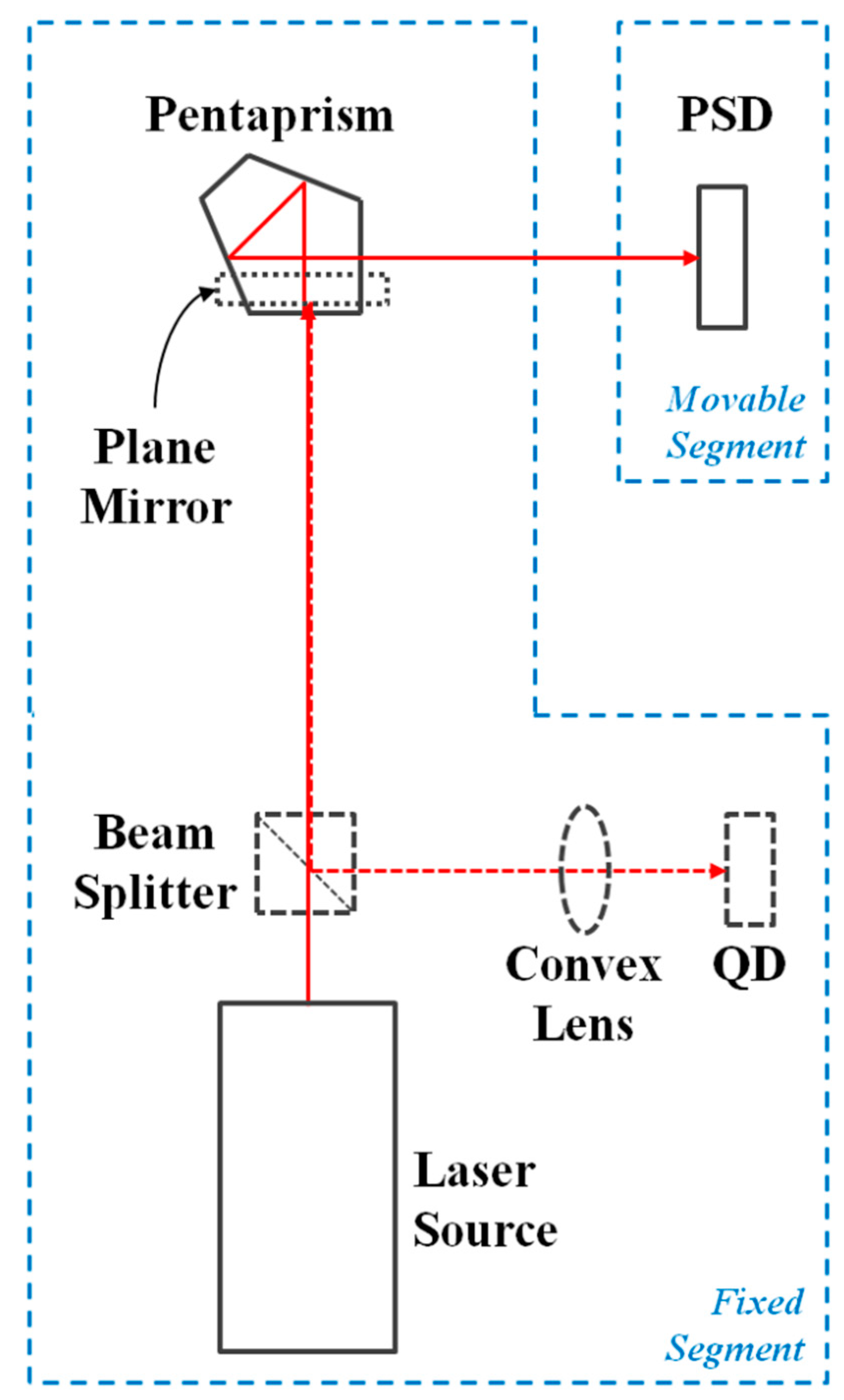
In addition to dual laser interferometer and PSD, a pentaprism module with a lifting mechanism was also developed for the geometric error measurement in this study. The pentaprism (BPP-12.7, Newport, Irvine, CA, USA), a five-sided reflecting prism, was utilized to deflect the incident laser beam by exactly 90°, regardless of the incident angle. For keeping the maximum intensity of the reflected beam, the light receiver of the laser interferometer and a plane mirror were utilized to ensure the altitude angle between the pentaprism module and the laser source.
The setup process of the pentaprism module is described as follows: The plane mirror placed above the pentaprism is first lifted up to receive the laser beam by adjusting the lifting mechanism of the pentaprism module for refracting the incident laser beam back to the optical field receiver of the laser source. The altitude angle between the laser source and the pentaprism module is ensured by keeping the maximum optical intensity of the backed beam. After ensuring the altitude angle with the maximum reflected beam intensity, the pentaprism is then lifted up to receive the laser beam by again adjusting the lifting platform of the pentaprism module.
The optical arrangement of the beam module and the pentaprism module is shown in Figure 1.
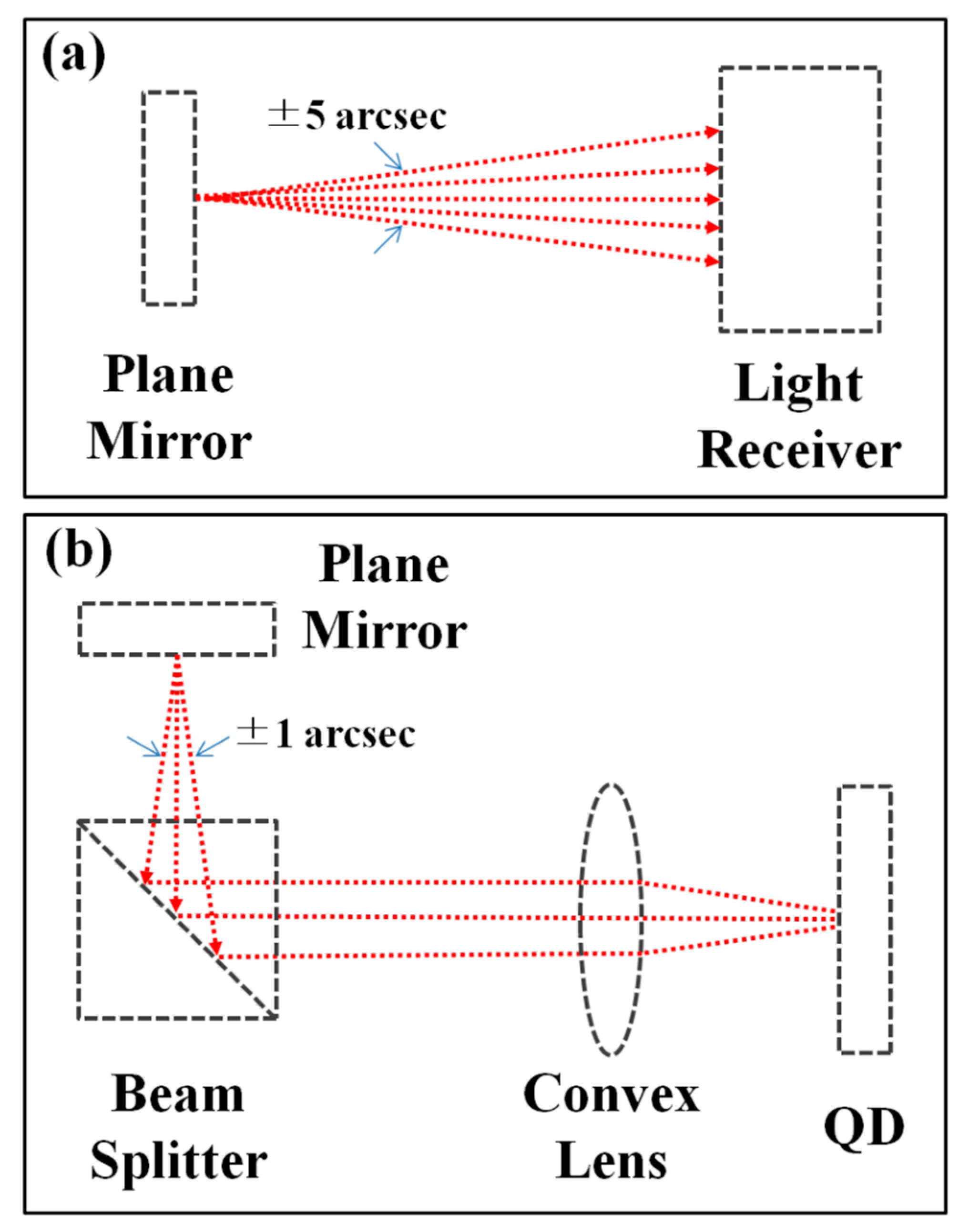
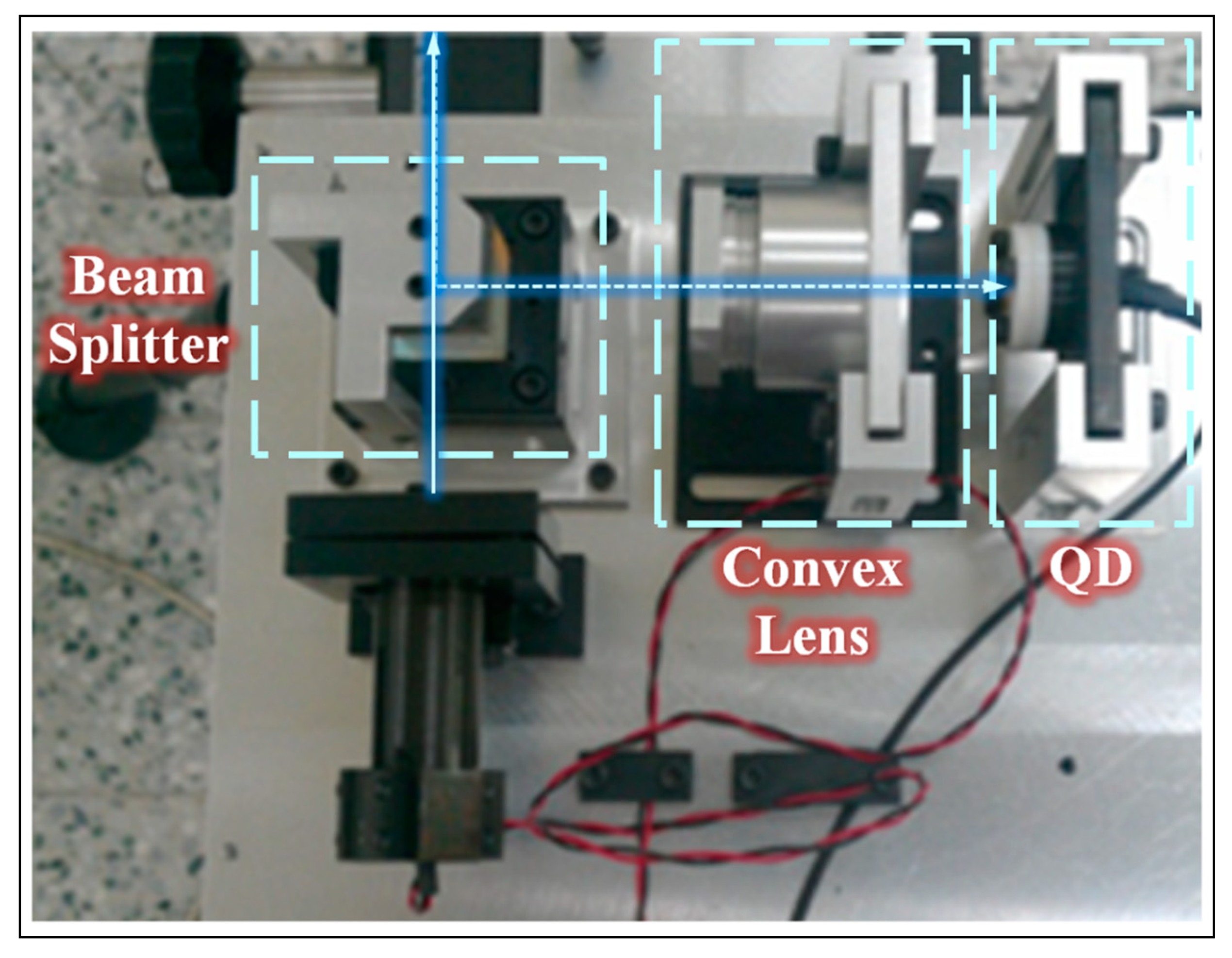
For the commercial laser interferometer, the coincidence between the reflected and the incident beams could be achieved by perpendicularly adjusting the altitude angle of the incident beam to the plane mirror by its light receiver according to the Michelson principle. However, with the feedback of calibration results, it was confirmed that the tolerance error of the “100% coincidence” measured by the commercial laser interferometer was about ±5 arcsec, which could result in poor measuring repeatability, especially for the case of long-range measurements, as shown in Figure 2a. Therefore, an altitude angle adjustment module composed of a beam splitter, a convex lens, and a QD was proposed based on the autocollimator principle [18] for obtaining higher calibration repeatability, as shown in Figure 2b and Figure 3. With the proposed module, the reflected beam was deflected by the beam splitter and passed through a convex lens onto QD, and the tolerance error of the “100% coincidence” could be reduced to ±1 arcsec.
Testing results showed that the perpendicularity repeatability (3σ) with a measuring distance of 2 m was greatly reduced from 5.7 arcsec (27.63 μm/m) to 1.6 arcsec (7.56 μm/m), proving the feasibility of the proposed altitude angle calibration module. Practically, the altitude angle between the laser source and the pentaprism could be calibrated using the first method based on the Michelson principle mentioned above for laboratories and factories owing to the Agilent 5529A interferometer, and the second method, based on autocollimator principle mentioned above, could be used for high calibration repeatability applications.
2.2. Straightness Measurement Module
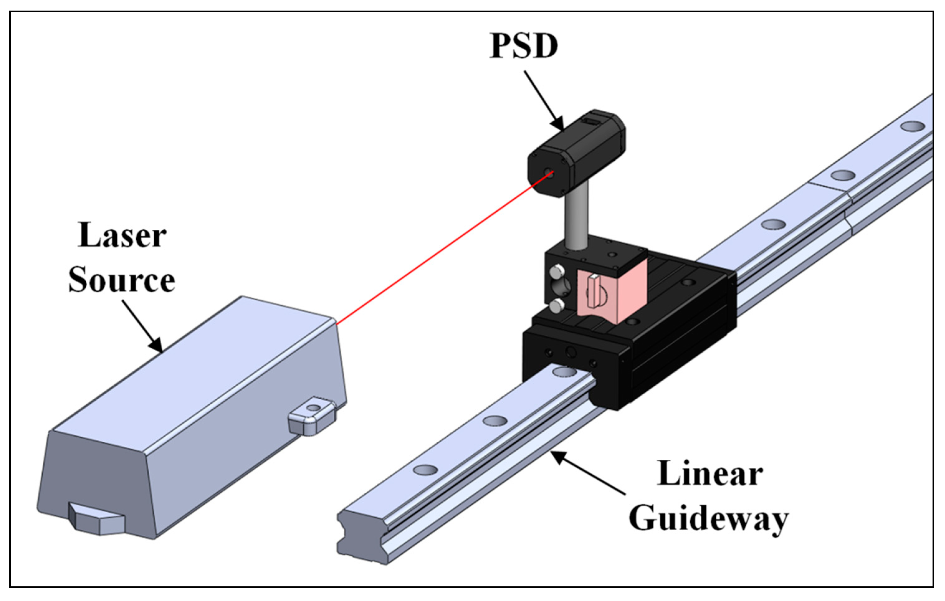
The proposed straightness measurement module is composed of a PSD (Dual lateral), a signal processor, a data acquisition card (USB-6210, National Instruments Co., Taipei, Taiwan), and a laser source, as shown in Figure 4. The straightness error is the extent of the actual path deviating from a straight line, which can be divided into horizontal and vertical straightness errors [19].
The linear least-squares method is used for analyzing the geometric errors in this study, which is to find the equation of the straight line that minimizes the sum of the squares of deviations calculated from PSD-measured points:
The straightness error can be expressed as:
2.3. Perpendicularity Measurement Module
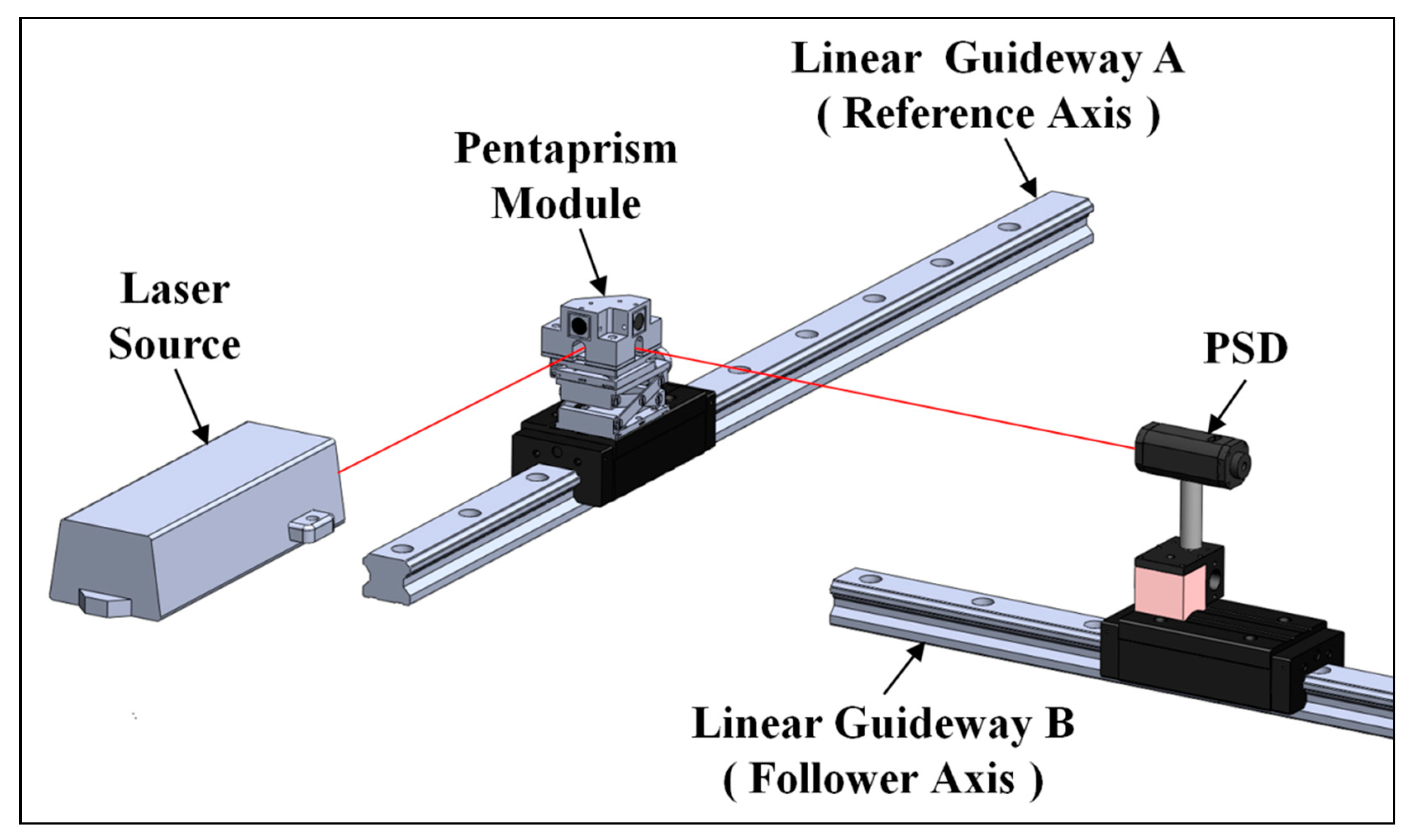
Figure 5 shows the proposed perpendicularity measurement system, which was mainly composed of the straightness module and the pentaprism module, as mentioned in previous sections. The perpendicularity measurement process is described as follows:
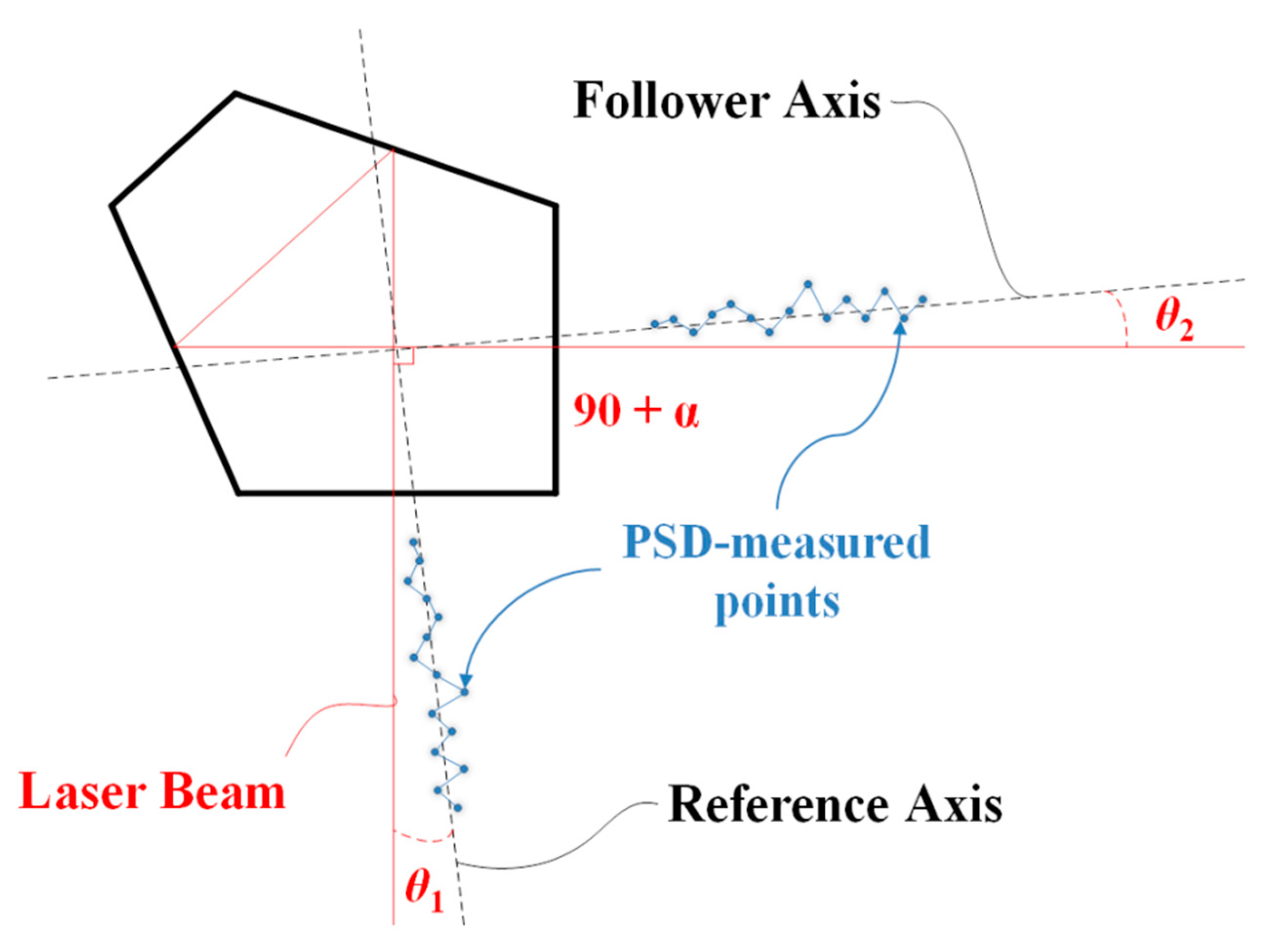
First, the deviation angle of the incident beam θ1 (as shown in Figure 6) was calculated via the least-squares analysis of the measured points detected by the PSD set upon the linear guideway A.
Secondly, the PSD was moved and remounted on the linear guideway B; thereupon, the pentaprism module was set at the cross-point of linear guideway A and the extended line of linear guideway B, allowing the incident beam be refracted by 90° and projected on the re-set PSD.
Finally, the deviation angle of the refracted beam θ2 was also calculated via the least-squares analysis of the PSD-measured points.
The perpendicularity error can be obtained by the arctangent relation of θ1, θ2, measured distance D, and the pentaprism error α (±30 arcsec), as shown in Figure 6:
2.4. Parallelism Measurement Module
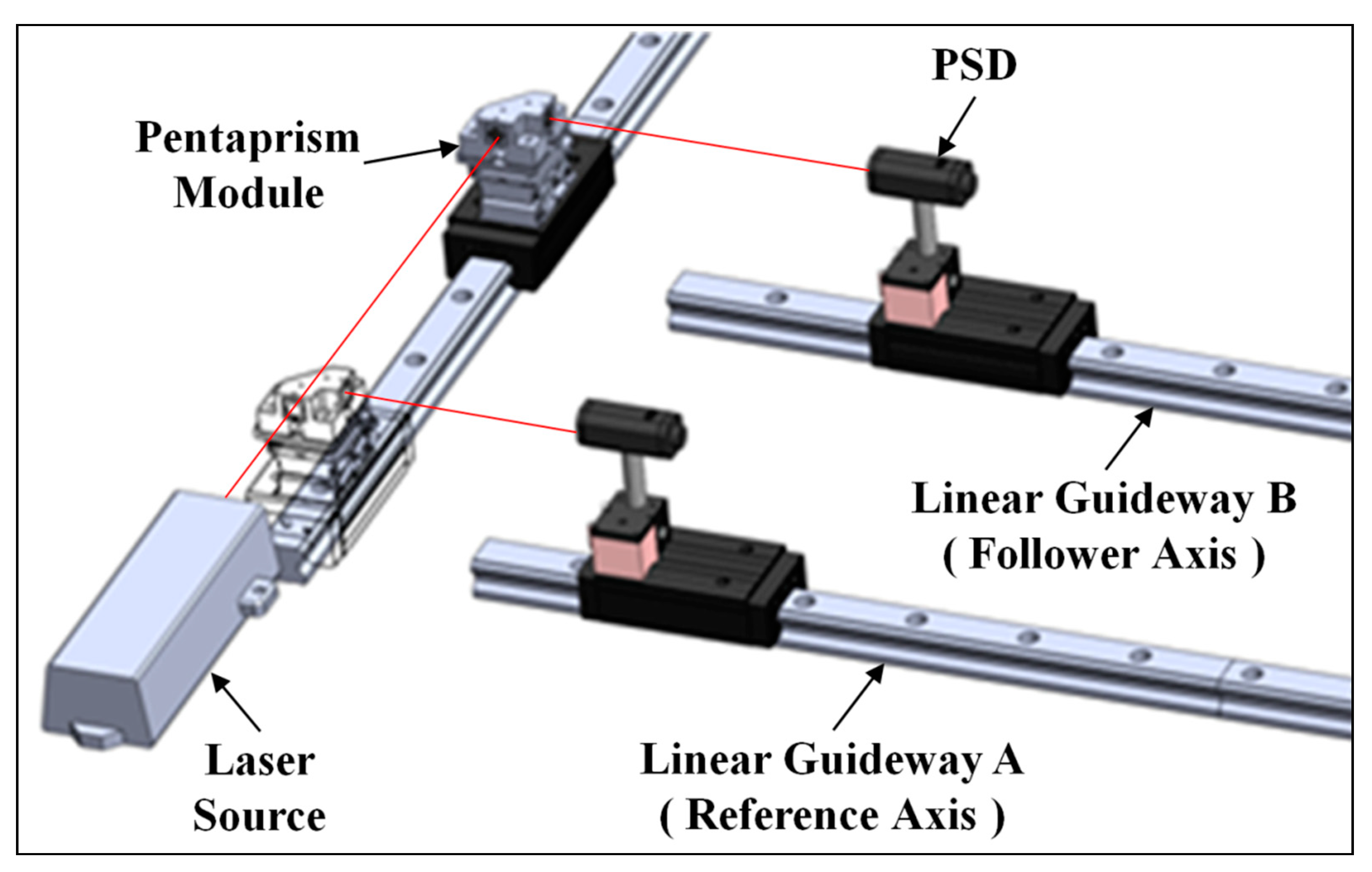
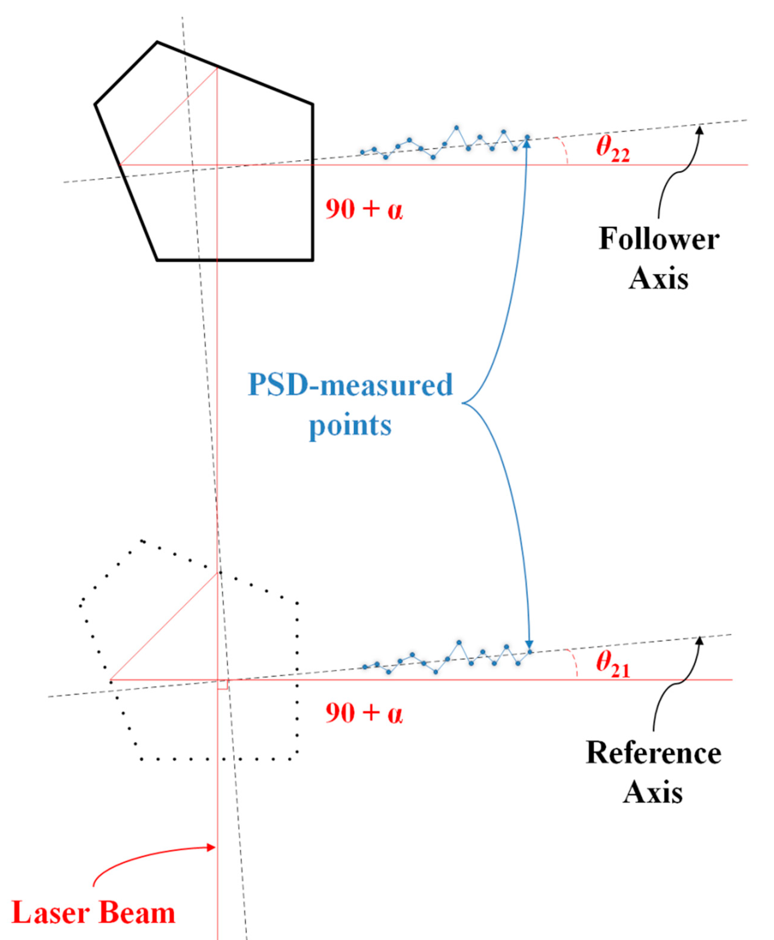
The measurement and setup principle of the parallelism is almost the same as that of perpendicularity described in the previous section; the only difference is the beam path utilized in the measurement, as shown in Figure 7.
The deviation angles of the refracted beam and were also calculated via the least-squares analysis of the measured points detected by the PSD set upon the linear guideway, respectively. The perpendicularity error can be obtained by the arctangent relation of , , and the measured distance , as shown in Figure 8:
3. Uncertainty Analysis
The proposed system comprises one laser source, one pentaprism module, and one PSD module; therefore, any setup errors among any of these components absolutely influence the system uncertainty. The details are explained below.
3.1. Laser Source Setup
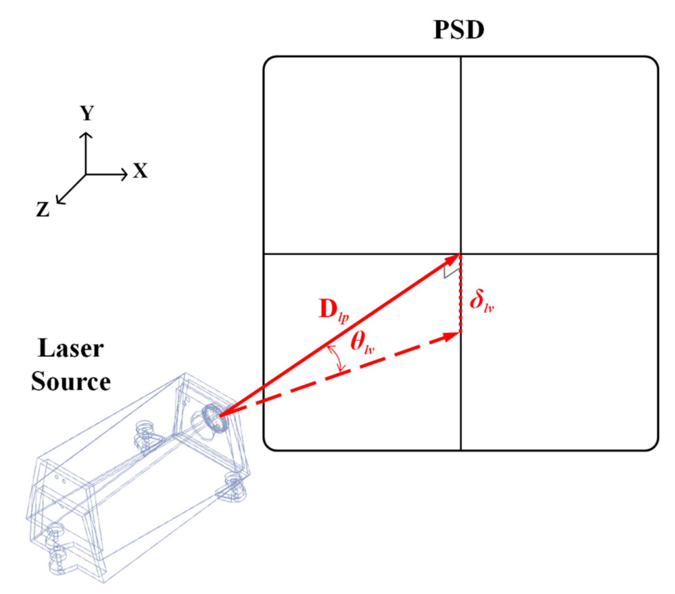
During the measuring process, the laser source setup could be affected by the unstable foundation, machine operation, crane movement, staff walking, etc. The longer the distance is, the worse the measurement results; therefore, there is a need of an error analysis toward the laser source.
As depicted in Figure 9, suppose the distance between the laser source and the fixed end is , the error angle of laser source at vertical direction () will generate an error :
Table 1 lists the setup errors in the vertical and horizontal directions of the laser source due to surface ground vibration with various measurement distances according to Equation (5).
3.2. PSD Setup
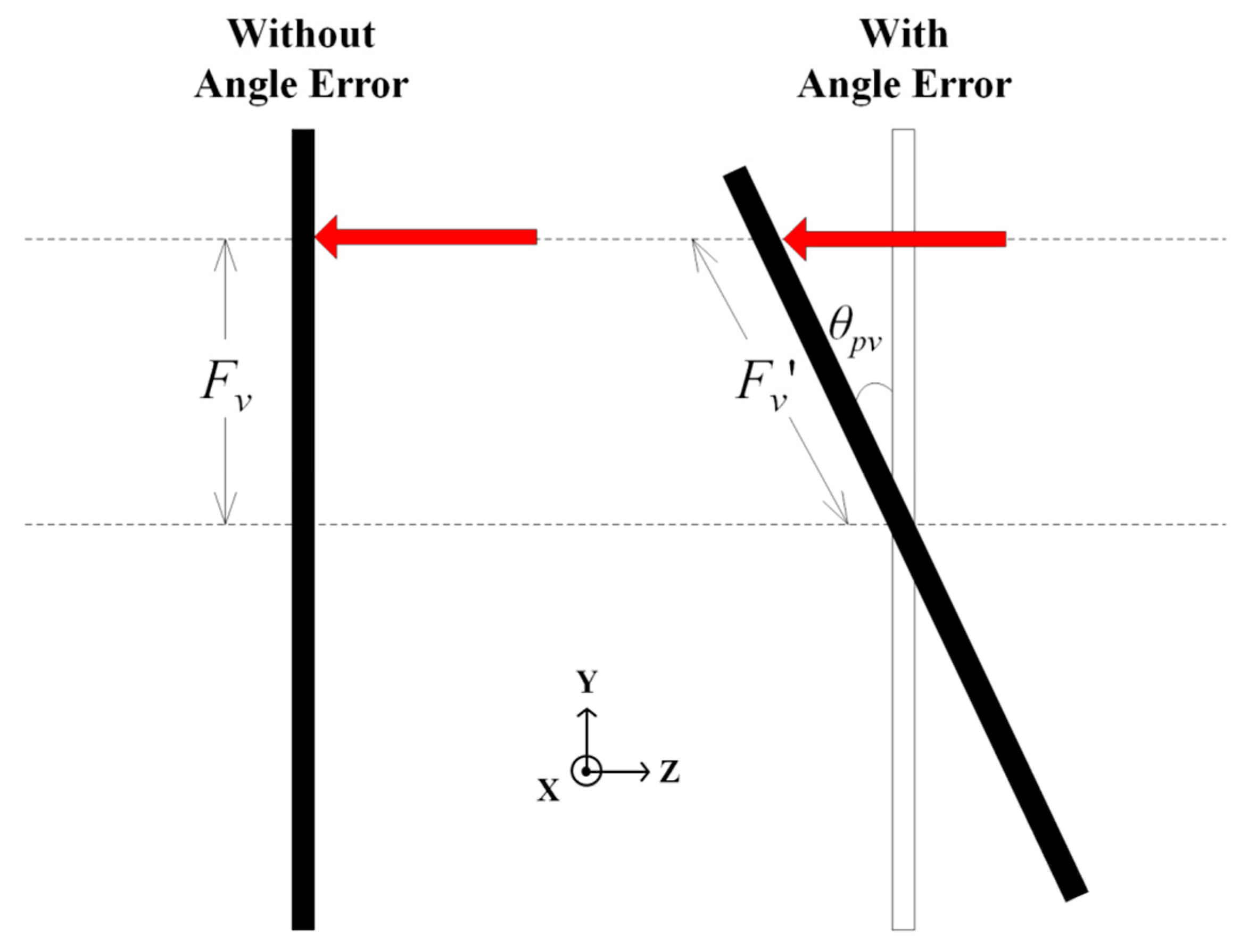
There is usually an angle error due to the setup of PSD, and it will result in a cosine error in the vertical or horizontal direction, as shown in Figure 10. Assume is the error measured in the vertical direction from the center of the PSD detection area, and is the error originated from PSD setup when an angle deviation exists, we get:
Table 2 lists the setup errors in the vertical and horizontal directions of the laser PSD due to surface ground vibration with various measurement distances according to Equation (6).
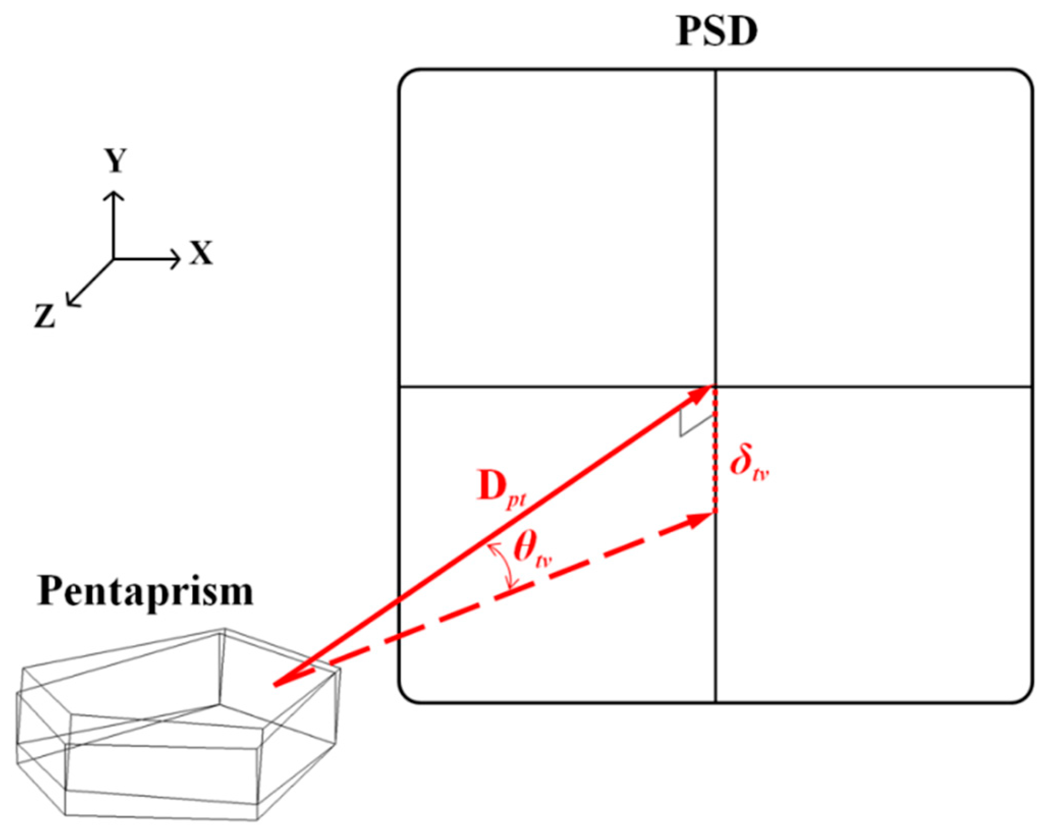
3.3. Pentaprism Setup
The setup error originated from the pentaprism module used in the perpendicularity and parallelism measurement was analyzed, as depicted in Figure 11. Suppose the distance between the laser source and the fixed end is , the error angle of the laser source in the vertical direction () will generate an error :
The error analysis table of pentaprism in the vertical or horizontal direction is the same as Table 1.
The measurement uncertainty of the proposed system can be obtained via partial differentiation of the linear displacements, or , along the horizontal or vertical direction (x-axis or y-axis), which were, respectively, measured by the position deviation of the light spot along the x-axis or y-axis of PSD. The linear displacements ( and ) can be expressed as:
Take the partial derivatives of in Equations (8) and (9) with respect to the corresponding uncertain factors , , and , we get:
The horizontal and vertical straightness measurement uncertainties ( and ) of compound errors can be expressed as:
In the present study, for vertical vibration in the environment is always higher than horizontal vibration; therefore, the error angle of laser source at vertical direction can be assumed to three times of the horizontal direction as: The horizontal direction : 20 arcsec and the vertical direction : 60 arcsec; otherwise the travel distance of the laser beam passes through the pentaprism were much longer, therefore, the error angle of pentaprism can be assumed to be twice that of the laser source as: The horizontal direction : 40 arcsec, and the vertical direction : 120 arcsec. Based on the calibration experiment, the angle setup error of PSD at the horizontal and vertical direction, and , can be assumed to be less than ±2.5°, the PSD measurement error F can be assumed to be less than ±100 μm, and the setup errors of the measuring distance, and , can be both assumed to be 1 m. Thus, the measurement uncertainties, and , were estimated to be ±1.02 and ±3.06 μm from Equations (12) and (13), respectively.
4. System Verification
4.1. Altitude Angle between Laser Source and Pentaprism
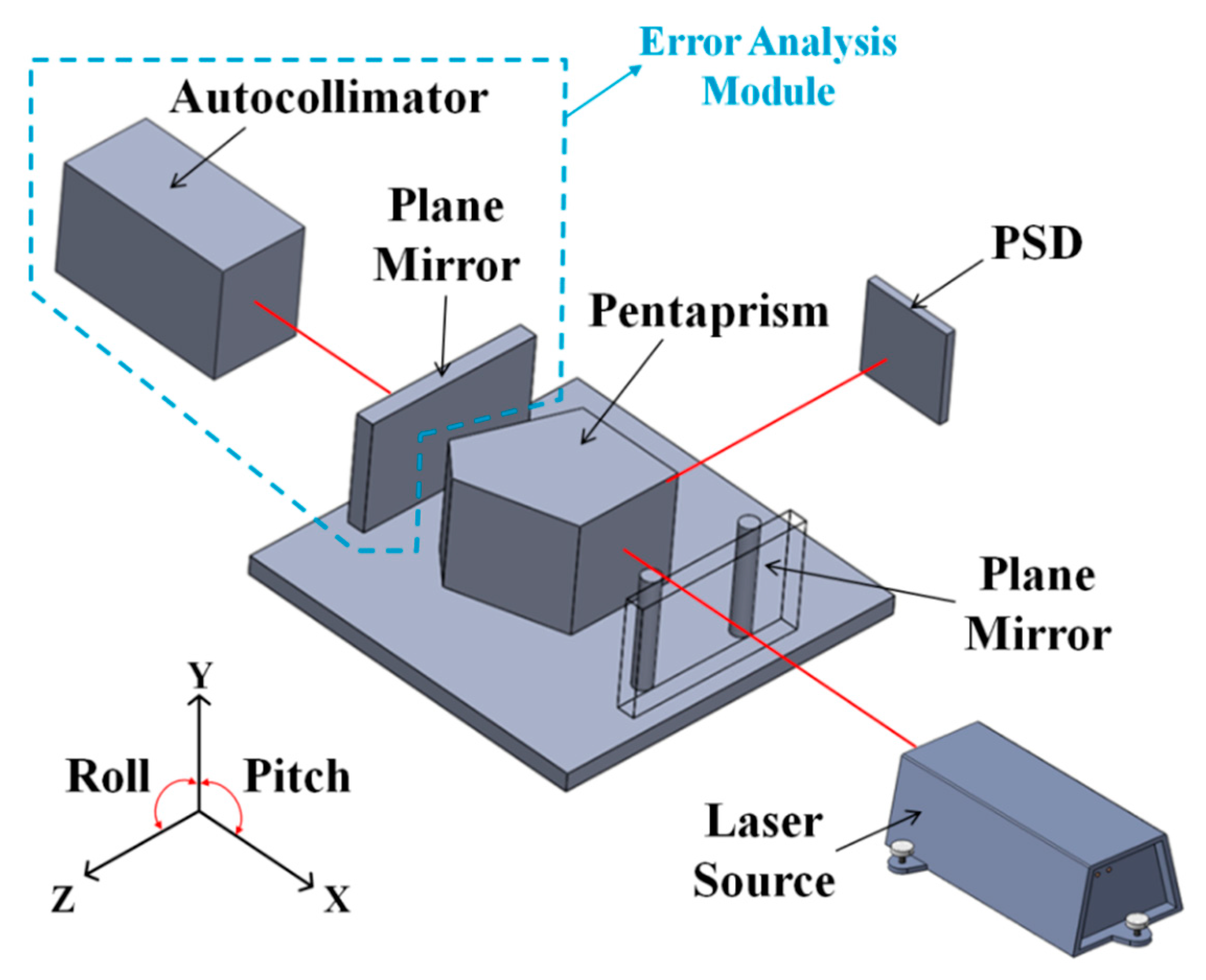
The measurement error originated from the pentaprism module setup in the perpendicularity and parallelism measurement was analyzed by an autocollimator and a mirror both set behind the pentaprism, as shown in Figure 12. The uncertainty analysis of the pentaprism setup in the different angle lists in Table 3.
4.2. Straightness Measurement
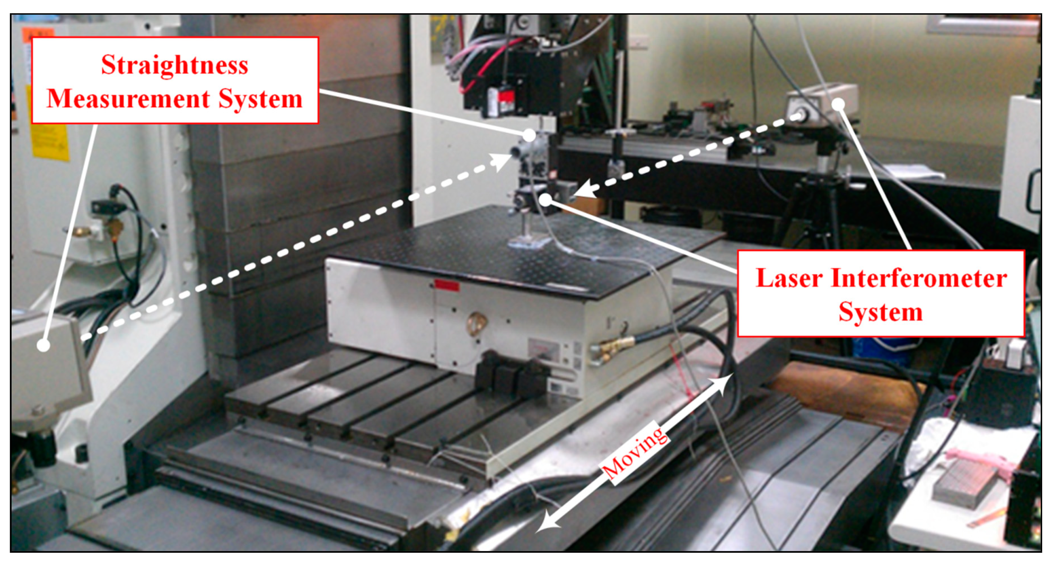
The verification of the proposed straightness system was conducted by using a dual laser interferometer (5529A, Agilent Tech., Santa Clara, CA, USA) as a reference standard to simultaneously measured straightness errors of a three-axis machine tool (KSC-611, KENT, New Taipei City, Taiwan) with the measurement distance of 1000 mm in a well air-conditioned laboratory, as shown in Figure 13.
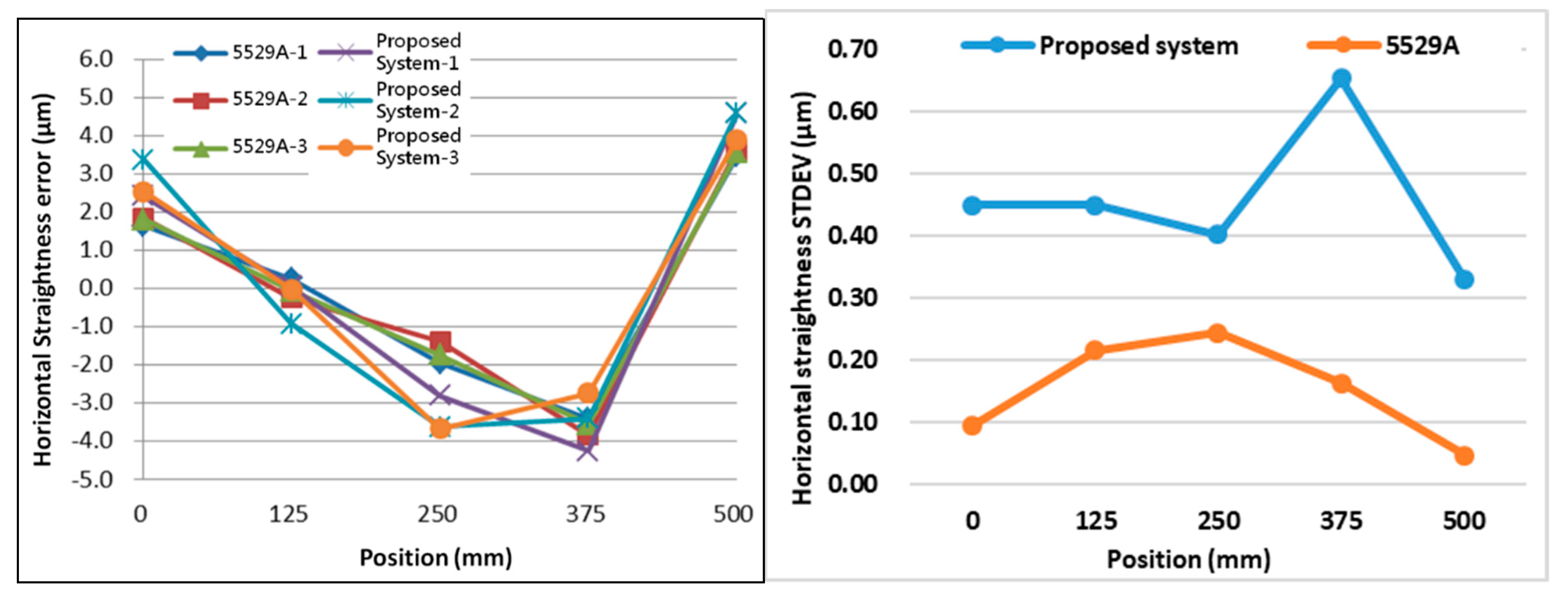
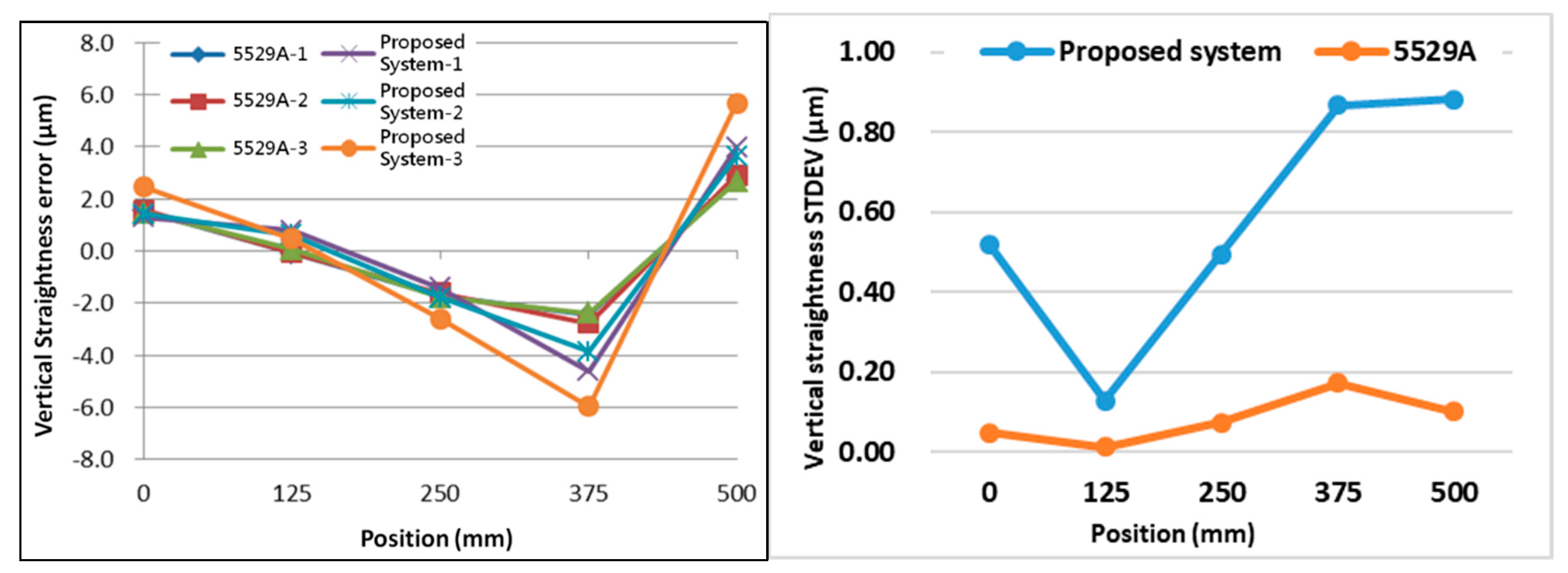
The results of horizontal straightness measurements are shown in Figure 14. The average horizontal straightness errors measured by 5529A and the proposed system were found to be 7.2 ± 0.2 μm and 8.2 ± 0.5 μm, respectively. The results of vertical straightness measurements are shown in Figure 15. It was observed that the average vertical straightness errors measured by 5529A and the proposed system were 5.3 ± 0.3 μm and 9.2 ± 1.7 μm, respectively. The residual error of the horizontal straightness and vertical straightness are found to be ±1.3 µm and ±5.3 µm, respectively.
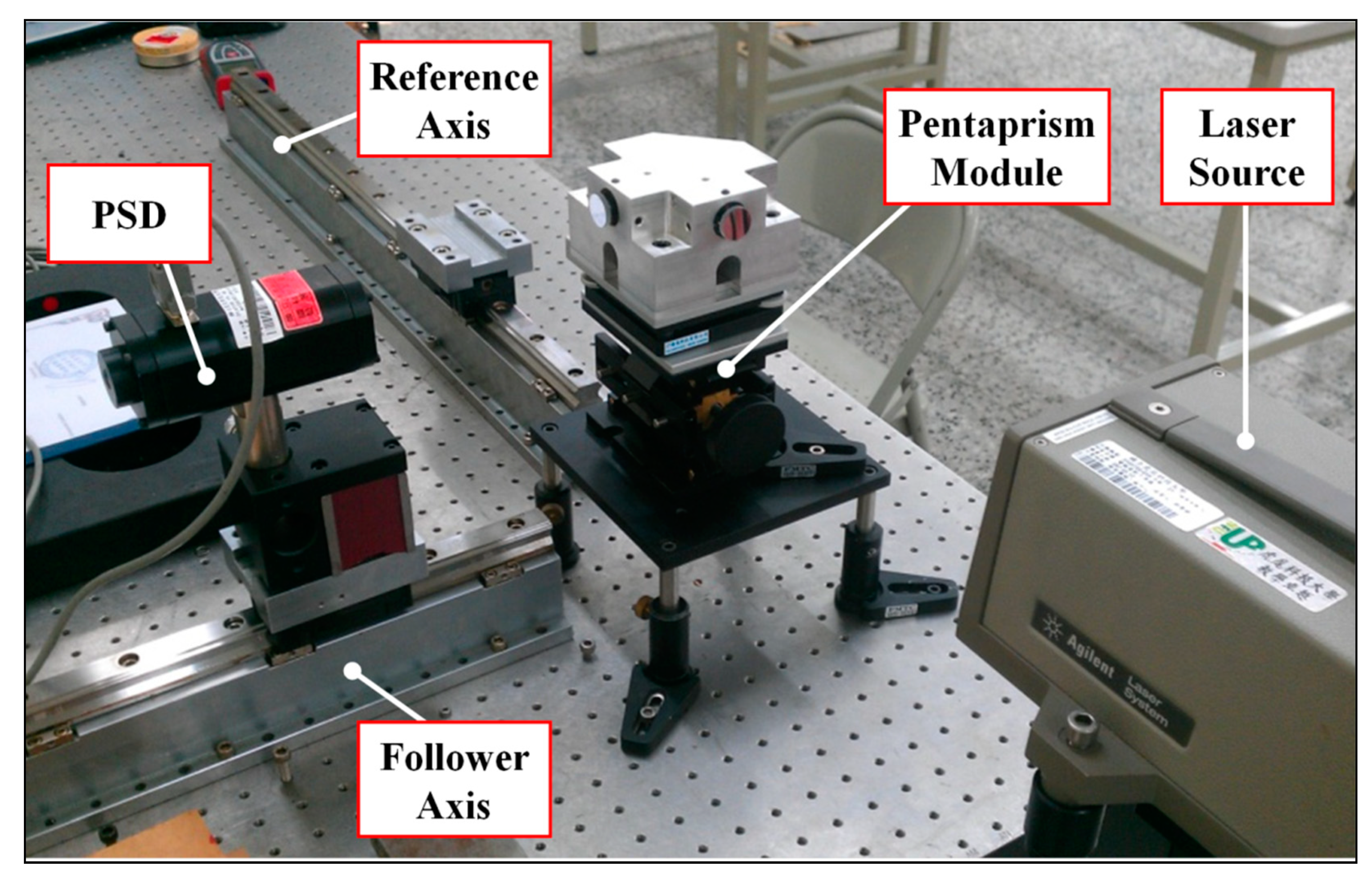
4.3. Perpendicularity Measurement
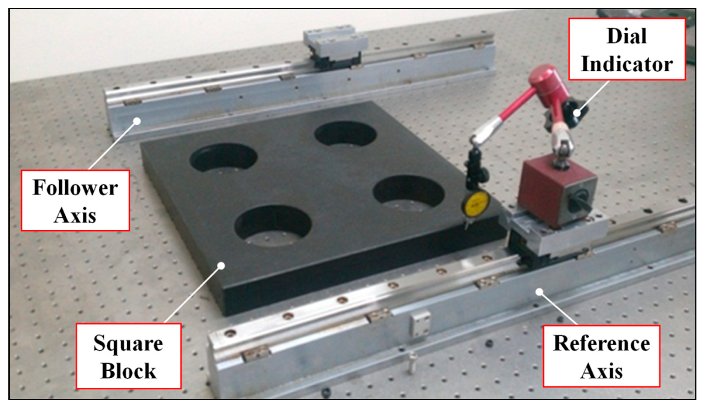
The verification of proposed perpendicularity system was conducted by using one square block (CVA239, Keysight Tech., Taipei, Taiwan), one dial indicator (GT1453sp, Girod-Tast Instrument, 2738 Court, Switzerland), and two linear guideways (both 400 mm) in a well air-conditioned laboratory. The dial indicator was utilized to examine the measurement results of the square block.
The linear guideway was first aligned parallel to each other using the square block and then measured by the proposed system, as shown in Figure 16 and Figure 17. The average perpendicularity error measured by the square block and the proposed system were 4.0 ± 0.8 μm and 2.7 ± 0.9 μm, respectively.
4.4. Parallelism Measurement
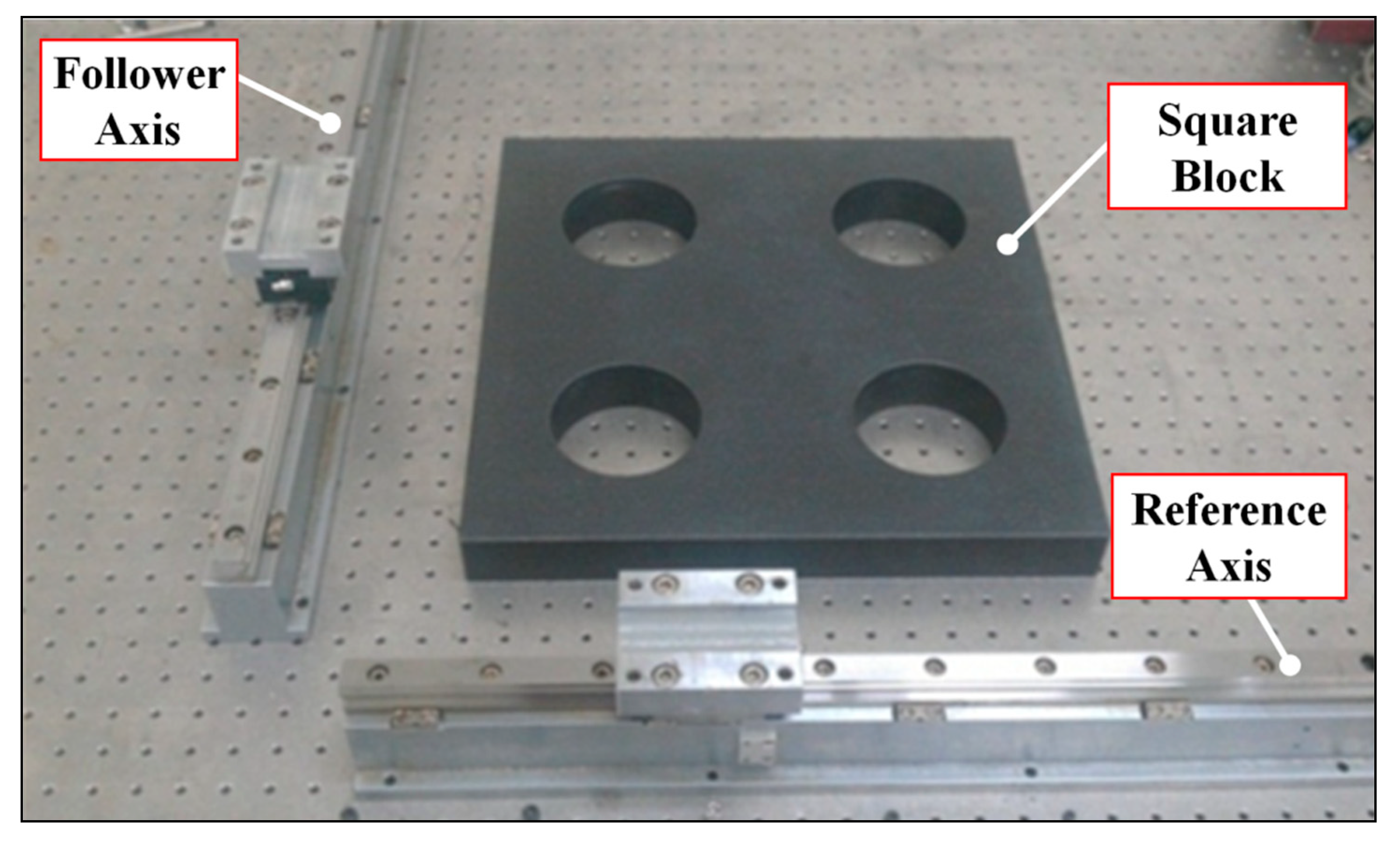
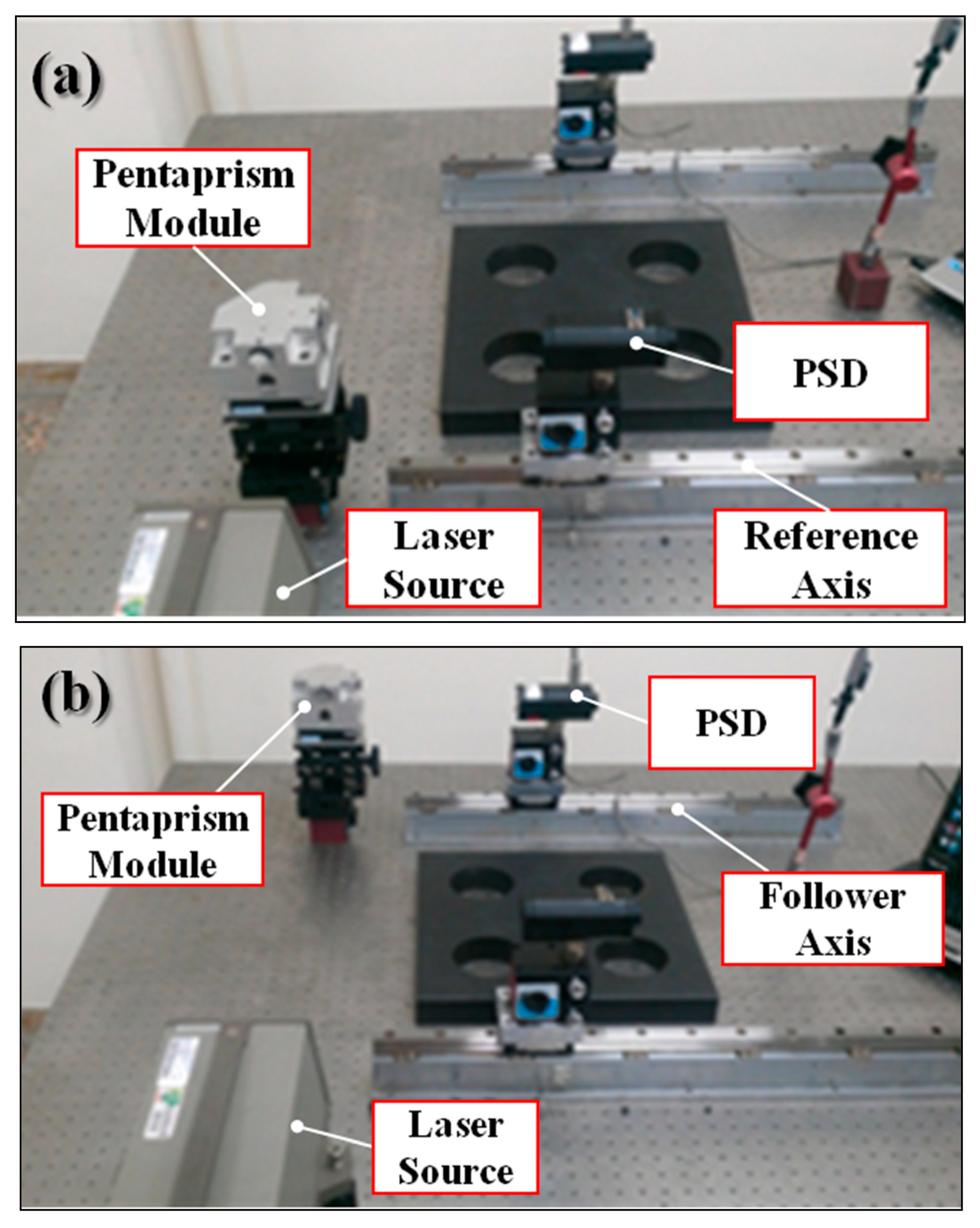
The verification of the proposed parallelism system was also conducted by using one square block, one dial indicator, and two linear guideways (both 400 mm) in a well air-conditioned laboratory. Figure 18 and Figure 19 show the verification setup of the square block and the proposed system, respectively.
The linear guideway was first aligned parallel to each other using a square block and then measured by the proposed system, as shown in Figure 17 and Figure 18. The average parallelism error measured by the square block and the proposed system were 11.3 ± 0.5 μm and 11.2 ± 0.5 μm, respectively.
Table 5 shows the verification results of the long-travelling geometric error measurement system; obviously, the measurement difference between the commercial instrument/tool and the proposed system was very small, except for the vertical straightness error (>5 μm). This phenomenon may originate from the vertical ground vibration of the laser source, which mainly depends on the measurement environment, as discussed in the above uncertainty analysis.
4.5. Application of Proposed System
The proposed system was used in several Taiwanese domestic machine tool and precision stage manufacturer. The application included straightness, perpendicularity, and parallelism measurement.
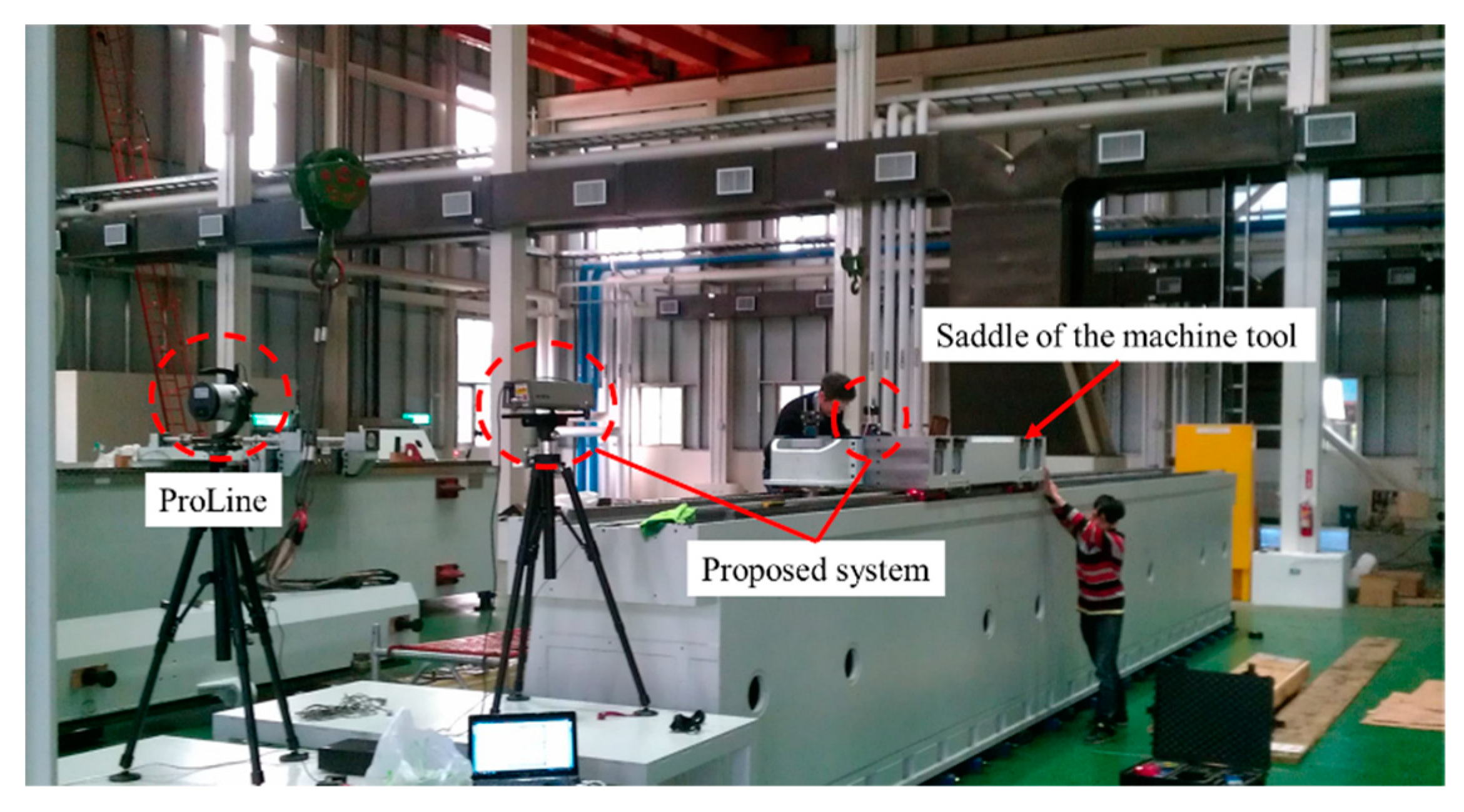
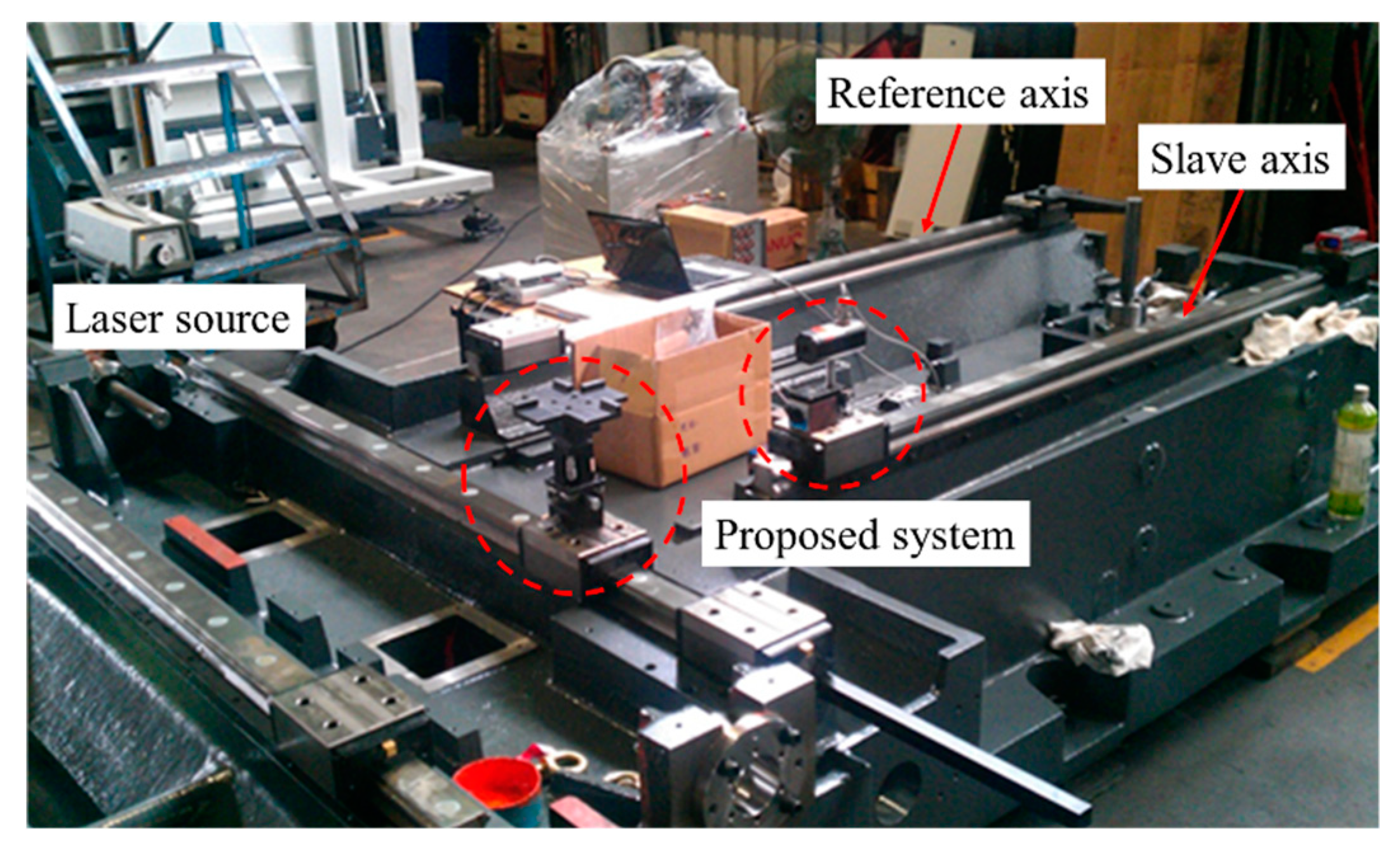
The first case was for the straightness measurement of machine tool in fabrication site. We compared the proposed system with commercial straightness measurement equipment (ProLine, Status Pro Maschinenmesstechnik GmbH, Bochum, Germany). Total measurement range was 6000 mm, the application setup is shown in Figure 20, the proposed system installed in parallel with the ProLine on the saddle of the machine tool. The measurement results are shown in Table 6.
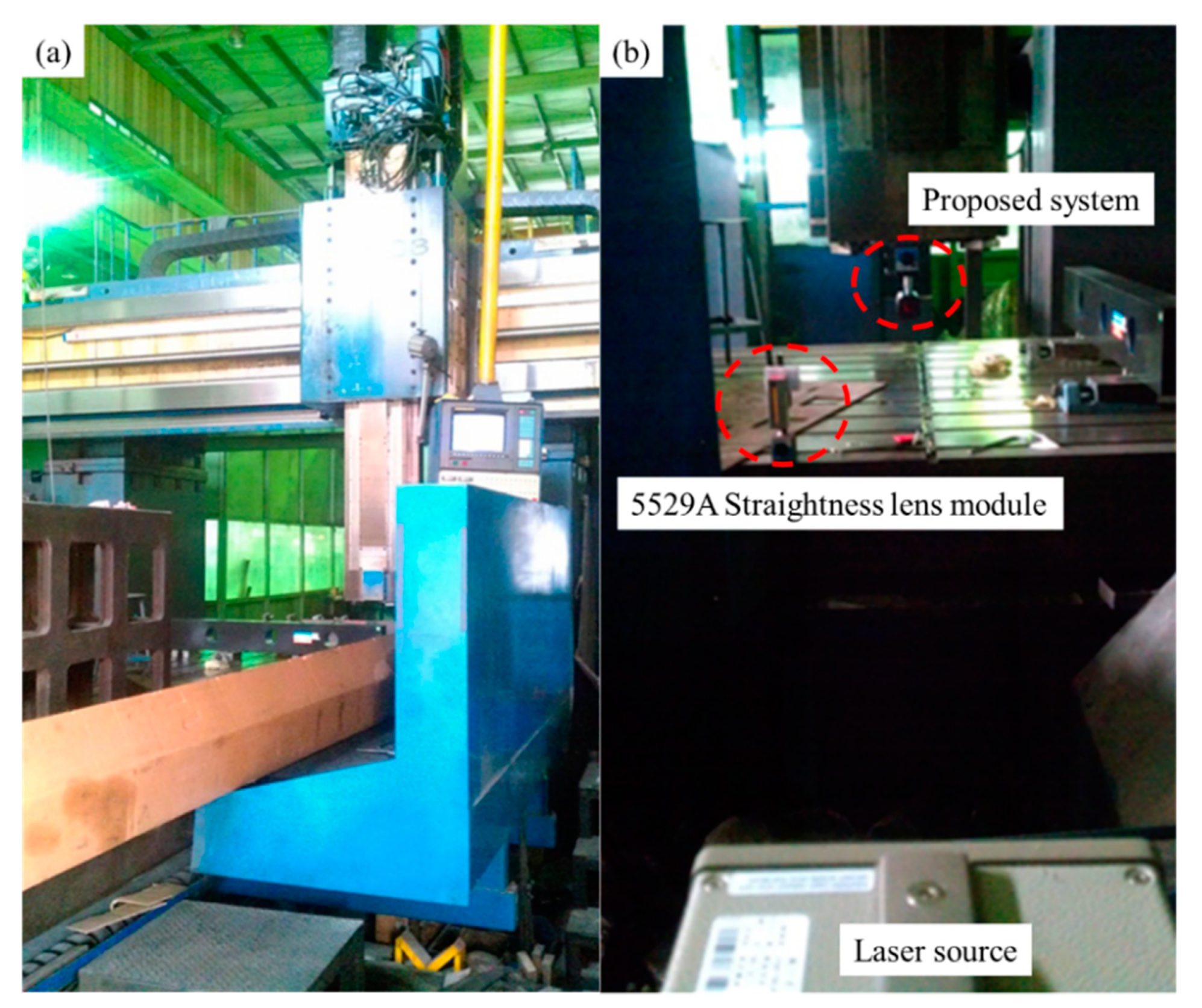
The second case was for the straightness measurement of double-column machine tool. We compared the proposed system with commercial laser interferometer (5529A, Agilent Tech., Santa Clara, CA, USA). The total measurement range was 2000 mm; the application setup is shown in Figure 21. The measurement results are shown in Table 7.
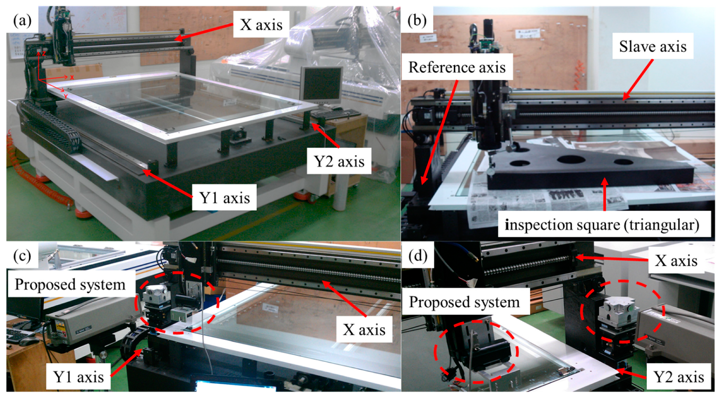
The third case was for the perpendicularity measurement of AOI equipment. In this case, the reference measurement value was provided by the third company with the inspection square (triangular) (1200 mm grade 0, OPUS, Taoyuan, Taiwan). The total measurement range was 1100 mm; the application setup is shown in Figure 22. The measurement results are shown in Table 8.
5. Conclusions
In this study, a multipurpose geometric error measurement system mainly composed of a laser source and a self-developed optical module has been developed for the measurement of straightness, perpendicularity, and parallelism errors for a linear guideway assembly process.
This includes two adjustment methods using an in-lab-developed optical module capable of calibrating the altitude angle of the pentaprism: The first method is designed for ease of operations based on Michelson principle and uses a laser interferometer as the light receiver, and the second one is aimed for high calibration-repeatability based on autocollimator principle using QD to replace the light receiver. The measured data are analyzed by the least-squares method in order to obtain corresponding geometric errors; meanwhile, the system uncertainty analysis is also conducted for the laser source, PSD, and pentaprism module for evaluating the system performance.
The features of the multipurpose geometric error measurement system presented in this paper are described as follows:
- (a)
- There is no need to reset the system if the laser source is sheltered during the measurement process;
- (b)
- The horizontal and vertical straightness errors can be obtained in one measurement;
- (c)
- The system is capable of applying to the linear guideway assembly process of various double-column, three-axis, and five-axis machine tools;
- (d)
- The residual error of the horizontal straightness, vertical straightness, perpendicularity, and parallelism are found to be ±1.3 µm, ±5.3 µm, ±1.2 µm, and ±0.1 µm, respectively, which are better compared to those detected by the commercial laser interferometer and granite reference blocks.
Author Contributions
The authors contributed equally to the manuscript.
Acknowledgments
The present work was funded by the Ministry of Economic Affairs (MoEA) and the Ministry of Science and Technology (MoST) of Taiwan (Republic of China), the authors would like gratefully express their sincere acknowledgment to MoEA and MoST.
Conflicts of Interest
The authors declare no conflict of interest.
References
- Sommargren, G.E. Linear/Angular Displacement Interferometer for Wafer Stage Metrology. Proc. SPIE 1989, 1088, 268–273. [Google Scholar]
- Nakamura, O.; Goto, M. Four-beam laser interferometry for three-dimensional microscopic coordinate measurement. Appl. Opt. 1994, 33, 31–36. [Google Scholar] [CrossRef] [PubMed]
- Lee, C.-W.; Kim, S.-W. An ultraprecision stage for alignment of wafers in advanced microlithography. Precis. Eng. 1997, 21, 113–122. [Google Scholar] [CrossRef]
- Menq, C.H.; Zhang, J.H.; Shi, J. Design and development of an interferometer with improved angular tolerance and its application to x-y theta measurement. Rev. Sci. Instrum. 2000, 71, 4633–4638. [Google Scholar] [CrossRef]
- Zhang, Z.; Menq, C.H. Laser interferometric system for six-axis motion measurement. Rev. Sci. Instrum. 2007, 78, 1–8. [Google Scholar] [CrossRef] [PubMed]
- Liu, C.-H.; Jywe, W.-Y.; Jeng, Y.-R.; Hsu, T.-H.; Li, Y.-t. Design and control of a long-traveling nano-positioning stage. Precis. Eng. 2010, 34, 497–506. [Google Scholar] [CrossRef]
- Ni, J.; Huang, P.S.; Wu, S.M. A Multi-Degree-of-Freedom Measuring System for CMM Geometric Errors. J. Eng. Ind. 1992, 114, 362–369. [Google Scholar]
- Huang, P.S.; Ni, J. On-line error compensation of coordinate measuring machines. Int. J. Mach. Tools Manuf. 1995, 35, 725–738. [Google Scholar] [CrossRef]
- Shimizu, S.; Lee, H.S.; Imai, N. Simultaneous Measuring Method of Table Motion Error in 6 Degrees of Freedom. Int. J. Jpn. Soc. Precis. Eng. 1994, 28, 273–274. [Google Scholar]
- Chou, C.; Chou, L.-Y.; Peng, C.-K.; Huang, Y.-C.; Fan, K.-C. CCD-based CMM Geometrical error measurement using fourier phase shift algorithm. Int. J. Mach. Tools Manuf. 1997, 37, 579–590. [Google Scholar] [CrossRef]
- Fan, K.C.; Chen, M.J.; Huang, W.M. A six-degree-of-freedom measurement system for the motion accuracy of linear stages. Int. J. Mach. Tools Manuf. 1998, 38, 155–164. [Google Scholar] [CrossRef]
- Fan, K.-C.; Chen, M.-J. A 6-degree-of-freedom measurement system for the accuracy of X-Y stages. Precis. Eng. 2000, 24, 15–23. [Google Scholar] [CrossRef]
- Jywe, W.; Chen, C.J.; Hsieh, W.H.; Lin, P.D.; Jwo, H.H.; Yang, T.Y. A novel simple and low cost 4 degree of freedom angular indexing calibrating technique for a precision rotary table. Int. J. Mach. Tools Manuf. 2007, 47, 1978–1987. [Google Scholar] [CrossRef]
- You, F.-L.; Feng, Q.-B.; Zhang, B. Straightness error measurement based on common-path compensation for laser beam drift. Opt. Precis. Eng. 2011, 3, 004. [Google Scholar]
- Jywe, W.; Hsu, T.-H.; Liu, C.H. Non-bar, an optical calibration system for five-axis CNC machine tools. Int. J. Mach. Tools Manuf. 2012, 59, 16–23. [Google Scholar] [CrossRef]
- Huang, P.; Li, Y.; Wei, H.; Ren, L.; Zhao, S. Five-degrees-of-freedom measurement system based on a monolithic prism and phase-sensitive detection technique. Appl. Opt. 2013, 52, 6607–6615. [Google Scholar] [CrossRef] [PubMed]
- Chen, B.Y.; Xu, B.; Yan, L.P.; Zhang, E.Z.; Liu, Y.N. Laser straightness interferometer system with rotational error compensation and simultaneous measurement of six degrees of freedom error parameters. Opt. Express 2015, 23, 9052–9073. [Google Scholar] [CrossRef] [PubMed]
- Hsieh, T.H.; Jywe, W.Y.; Chen, S.L.; Liu, C.H.; Huang, H.L. Note: Development of a high resolution six-degrees-of-freedom optical vibrometer for precision stage. Rev. Sci. Instrum. 2011, 82, 056101. [Google Scholar] [CrossRef] [PubMed]
- Gao, W.; Arai, Y.; Shibuya, A.; Kiyono, S.; Park, C.H. Measurement of multi-degree-of-freedom error motions of a precision linear air-bearing stage. Precis. Eng. 2006, 30, 96–103. [Google Scholar] [CrossRef]
Figure 1.
System optical arrangement.

Figure 2.
The optical path of altitude angle calibration. (a) The tolerance error of the commercial laser interferometer and (b) the proposed module based on the autocollimator principle could reduce the tolerance error of the commercial laser interferometer.
Figure 2.
The optical path of altitude angle calibration. (a) The tolerance error of the commercial laser interferometer and (b) the proposed module based on the autocollimator principle could reduce the tolerance error of the commercial laser interferometer.

Figure 3.
The in-lab-developed module for altitude angle calibration.

Figure 4.
Schematic diagram of the straightness module.

Figure 5.
Schematic diagram of the perpendicularity module.

Figure 6.
Beam path of perpendicularity measurement.

Figure 7.
Schematic diagram of the parallelism module.

Figure 8.
Beam path of parallelism measurement.

Figure 9.
Vertical setup error of the laser source.

Figure 10.
Position sensing detector (PSD) setup error.

Figure 11.
Vertical setup error of the pentaprism.

Figure 12.
Schematic diagram of the pentaprism setup error detection.

Figure 13.
Verification setup of straightness measurement.

Figure 14.
Results of horizontal straightness measurement.

Figure 15.
Results of vertical straightness measurement.

Figure 16.
Verification setup of perpendicularity measurement using a square block.

Figure 17.
Verification setup of perpendicularity measurement using the proposed system.

Figure 18.
Verification setup of parallelism measurement using a square block.

Figure 19.
Verification setup of parallelism measurement using the proposed system: (a) Reference axis and (b) follower axis.
Figure 19.
Verification setup of parallelism measurement using the proposed system: (a) Reference axis and (b) follower axis.

Figure 20.
Case 1 straightness error measurement setup.

Figure 21.
Case 2 straightness error measurement setup on double column machine tool, (a) the double column machine tool and (b) the setup of 5529A laser interferometer straightness module and proposed system.
Figure 21.
Case 2 straightness error measurement setup on double column machine tool, (a) the double column machine tool and (b) the setup of 5529A laser interferometer straightness module and proposed system.

Figure 22.
Case 3 perpendicular error measurement setup. (a) The Automated optical inspection (AOI) equipment to be measured, (b) the inspection square (triangular) measurement setup, (c) the Y1┴X measurement setup of proposed system, and (d) the Y2┴X measurement setup of proposed system.
Figure 22.
Case 3 perpendicular error measurement setup. (a) The Automated optical inspection (AOI) equipment to be measured, (b) the inspection square (triangular) measurement setup, (c) the Y1┴X measurement setup of proposed system, and (d) the Y2┴X measurement setup of proposed system.

Figure 23.
Case 4 parallelism error measurement setup.


Table 1.
Error analysis of the laser source at vertical or horizontal directions.
| 1000 | 0.1 | 0.5 |
| 1000 | 0.5 | 2.4 |
| 1000 | 1 | 4.8 |
Table 2.
Error analysis of the PSD setup.
| 100 | 0.5 | 0.004 |
| 100 | 1 | 0.015 |
| 100 | 5 | 0.382 |
Table 3.
Uncertainty analysis of the pentaprism setup.
| Altitude Angle Error | Pitch (arcsec) | Standard Deviation (arcsec) | |||||
|---|---|---|---|---|---|---|---|
| Errors on PSD | 0 | 10 | 20 | 50 | 100 | ||
| Pitch (arcsec) | 0 | 0.76 | 0.70 | 4.19 | 6.15 | ±2.3 | |
| Yaw (arcsec) | 1.67 | 2.43 | 1.95 | 2.81 | ±0.4 | ||
Table 5.
Verification results of the proposed system.
| Measurement Distance (mm) | Commercial Instrument/Tool | Proposed System | ||||
|---|---|---|---|---|---|---|
| Straightness (Horizontal) | 1000 | 7.2 | ±0.2 | 8.2 | ±0.5 | 1.3 |
| Straightness (Vertical) | 5.3 | ±0.3 | 9.2 | ±1.7 | 5.3 | |
| Perpendicularity | 400 | 4.0 | ±0.8 | 2.7 | ±0.9 | 1.2 |
| Parallelism | 400 | 11.3 | ±0.5 | 11.2 | ±0.5 | 0.1 |
*
Table 6.
Case 1 straightness error measurement results.
| Straightness Error (Horizontal) | Straightness Error (Vertical) | |
|---|---|---|
| ProLine | 16 μm | 16 μm |
| Proposed system | 13.97 μm | 11.21 μm |
Table 7.
Case 2 straightness error measurement results.
| Straightness Error (Horizontal) | Straightness Error (Vertical) | |
|---|---|---|
| 5529A | 34 μm | 24 μm |
| Proposed system | 36 μm | 28 μm |
Table 8.
Case 3 perpendicularity error measurement results.
| Two-Axis Perpendicularity Displacement Error | Two-Axis Perpendicularity Angle Error | |
|---|---|---|
| Inspection square (triangular) | 5 μm/1.1 m | N/A |
| Proposed system Y1┴X | 14.3 μm/1.1 m | 2.68 arcsec |
| Proposed system Y2┴X | 14.1 μm/1.1 m | −2.66 arcsec |
Table 9.
The parallelism error measurement results.
| Parallelism Angle Error | Parallelism Displacement Error | |
|---|---|---|
| Company | 3.3 arcsec | 16 um/1.6 m |
| Proposed system | 1.09 arcsec | 5.29 um/ 1.6 m |
© 2019 by the authors. Licensee MDPI, Basel, Switzerland. This article is an open access article distributed under the terms and conditions of the Creative Commons Attribution (CC BY) license (http://creativecommons.org/licenses/by/4.0/).
Share and Cite
MDPI and ACS Style
Hsieh, T.-H.; Chen, P.-Y.; Jywe, W.-Y.; Chen, G.-W.; Wang, M.-S. A Geometric Error Measurement System for Linear Guideway Assembly and Calibration. Appl. Sci. 2019, 9, 574. https://0-doi-org.brum.beds.ac.uk/10.3390/app9030574
AMA Style
Hsieh T-H, Chen P-Y, Jywe W-Y, Chen G-W, Wang M-S. A Geometric Error Measurement System for Linear Guideway Assembly and Calibration. Applied Sciences. 2019; 9(3):574. https://0-doi-org.brum.beds.ac.uk/10.3390/app9030574
Chicago/Turabian StyleHsieh, Tung-Hsien, Po-Yu Chen, Wen-Yuh Jywe, Guan-Wu Chen, and Ming-Shi Wang. 2019. "A Geometric Error Measurement System for Linear Guideway Assembly and Calibration" Applied Sciences 9, no. 3: 574. https://0-doi-org.brum.beds.ac.uk/10.3390/app9030574
Note that from the first issue of 2016, this journal uses article numbers instead of page numbers. See further details here.