Experimental Study on Hysteretic Behavior of the Overlapped K-Joints with Concrete Filled in Chord


1
College of Civil and Hydraulic Engineering, Ningxia University, Yinchuan 750021, China
2
School of Civil Engineering, Southeast University, Nanjing 211100, China
3
Political and Legal Committee of Luoning County, Luoyang 471700, China
4
School of Civil Engineering, Southwest Jiaotong University, Chengdu 610031, China
*
Author to whom correspondence should be addressed.
Appl. Sci. 2019, 9(7), 1456; https://0-doi-org.brum.beds.ac.uk/10.3390/app9071456
Submission received: 12 March 2019
/
Revised: 2 April 2019
/
Accepted: 2 April 2019
/
Published: 7 April 2019
(This article belongs to the Special Issue Energy Dissipation and Vibration Control: Materials, Modeling, Algorithm and Devices)
Abstract
:Featured Application
This study is mainly aimed at the difficulty of welding hidden welds of the overlapped K-joints in engineering, and strengthening the grouting concrete in the chord to compensate for this defect. Furthermore, it can provide a technical reference for optimizing construction technology. The K-joints can be popularized and applied in civil engineering, hydraulic engineering, and even the military field in steel structures, bridge structures and airport terminals.
Abstract
Due to the insufficient radial stiffness of the steel tube, the cracking of the weld and the plastic deformation of the string often occur under the cyclic loading of the hollow section pipe joint. In order to avoid such a failure, the overlapped K-joints were strengthened by pouring different concrete into the chords. Furthermore, to explore the detailed effect of filling different concrete in a chord on the hysteretic behavior of the overlapped K-joints, six full-scale specimens were fabricated by two forms, which included the circular chord and braces, the square chord and circular braces, and the low cyclic loading tests, which were carried out. The failure modes, hysteretic curves and skeleton curves of the joints were obtained, and the bearing capacity, ductility and energy dissipation of the joints were evaluated quantitatively. The results showed that plastic failure occurs on the surface of the chord of the joints without filling concrete, while the failure mode of the joints filled with concrete in the chords was the tensile failure of the chords at the weld of the brace toe, and the compressive braces had a certain buckling deformation; The strengthening measures of concrete filled with chord can effectively improve the mechanical properties of the K-joints, the delay of the plastic deformation of the chord, and improve the bearing capacity of the K-joints. Contrarily, the ductility coefficient and the energy dissipation ratio of K-joints decreased with the concrete filled in the chord. The hysteretic behavior of the K-joints with a circular chord and brace was slightly better than that of the K-joints with a square chord and circular brace, and the hysteretic behavior of the K-joints strengthened with fly ash concrete, which was better than that of the K-joints strengthened with ordinary concrete. The results of ANSYS (a large general finite element analysis software developed by ANSYS Company in the United States) analysis agreed well with the experimental results.
1. Introduction
Steel tube truss structure has become one of the most common building structures in large public buildings at home and abroad due to its large torsional stiffness, excellent seismic performance [1,2,3,4,5,6], easy installation and easily meets the requirements of modern buildings for the sense of view. The joints do not need auxiliary components such as joint plates, which is beneficial to the improvement of the overall performance of the structure. However, due to the intersection of the members in the truss structure in the form of intersecting lines at the joints, the shape of the end section of the members was complex, and the joints were the major energy-dissipating parts under seismic loads. The seismic performance of the joints and the corresponding strengthening measures could not be ignored.
As one of the most widely used steel tubular truss joints in the field of building structure, the overlapped K-joints are generated in the actual construction process of the steel tubular truss when two braces (overlap brace and through brace) intersect on the surface of the chord. In overlapped K-joints, part of the through brace is hidden within the overlap brace, and the hidden toe of the through brace may or may not be welded to the chord [7]. Additionally, the bearing capacity of joints with hidden welds that are welded is higher than the joints with hidden welds unwelded, but with a reduction in ductility and hysteretic behavior [8,9,10,11]. What’s more, due to the insufficient radial stiffness of the chord, the steel truss composed of circular hollow section (CHS) members often undergoes plastic deformation or punching of the chord surface. Therefore, it is imperative to study the reinforcement measures for the overlapped K-joints. In China, CFST (Concrete Filled Steel Tube) truss girder was first applied in 1997 in the deck of the Zidong cable-stayed bridge in Nanhai City (Guangdong Province, China) [12]. Usually, only concrete is grouted into the chords of CFST truss structures, while no concrete was added to the braces [13]. Compared with the unstrengthened steel tube truss structure or concrete counter parts, the mechanical properties of steel tubular members grouting concrete have been effectively improved, such as the stiffness, the bearing capacity, buckling resistance [14,15,16,17,18,19], and impact resistance [20,21,22]. Welded steel tubular joints are usually used to connect the brace and chord of the Circular Hollow Section (CHS) structures and CFST structures, which includes K-joints, KK-joints, KT-joints, T-joints, N-joints, Y-joints, X-joints and so on.
The International Institute of Welding (IIW) [23] proposed an ultimate strength formula for CHS overlapped K-joints considering the local yielding failure of the braces. Zhao et al. [24] researched the static behavior of overlapped CHS K-joints and the impact of the hidden weld. The results showed that the influence of hidden welds on the static strength of overlapped K-joints was not obvious, while it may have influenced the failure mode. Sakai et al. [25] carried out static and fatigue testing on K-joints in truss girders strengthened with grouting concrete in the chord, and found that the fatigue strength of CFST joints was higher than that of CHS joints. Xu et al. [26] investigated the behavior of CFST trusses, obtaining the different failure modes of CFST trusses, and concluded that the joints in tensile showed weld failure and chord punching shear failure. Additionally, Chen et al. [27] presented the experimental and numerical research on double-skin circular CHS tubular X-joints under axial compression, and new design equations were proposed according to the failure mechanism on different joints. Hou et al. [28] studied the static behavior of concrete filled double skin steel tubular (CFDST) chord and CHS brace composite K-joints, and the effects of important parameters on joint strength were discussed based on experimental results. Feng et al. [29,30] investigated the performance of CFST joints under static loading. What’s more, Lesani et al. [31], Ju and Wang [32], Lvet al. [33], Rong et al. [34], Qian et al. [35] performed a series of experimental and analytical investigations on the mechanical behaviour of tubular joints and developed different formulas for determining the ultimate strength of the tubular joints. Yin et al. [36] conducted an experimental investigation on the hysteretic behavior of tubular N-joints. Moreover, Xu et al. [37], Qian et al. [38] and Tong et al. [39] carried out studies on the fatigue behavior of CFST joints.
In summary, the static and hysteretic behavior of tubular truss joints has been concerning for a long time, and additional experimental investigation is required to understand the behavior and propose a reliable design method of the joints of such types of tubular structures. For the overlapped K-joints, the welding of hidden welds brings forward some difficulties in construction, but research shows that the hidden weld that does not weld will have a certain impact on the bearing capacity of joints. Therefore, some studies have considered strengthening measures to improve the bearing capacity of joints. Lee et al. [40], Xia et al. [41] and Shao et al. [42] adopted different methods to strengthen the joints, and different strengthening effects were obtained. Based on the aforementioned discussion, this study was aimed at the overlapped K-joints with hidden weld welding problems, using the strengthening method of grouting concrete in the chords to explore the improvement of their bearing capacity, and mainly involved studying the hysteretic performance of the overlapped K-joints under cyclic loading, which could provide a certain theoretical basis and design reference for improving the bearing capacity of joints and optimizing the energy dissipation of the K-joints.
2. Experimental Study
2.1. Test Specimens
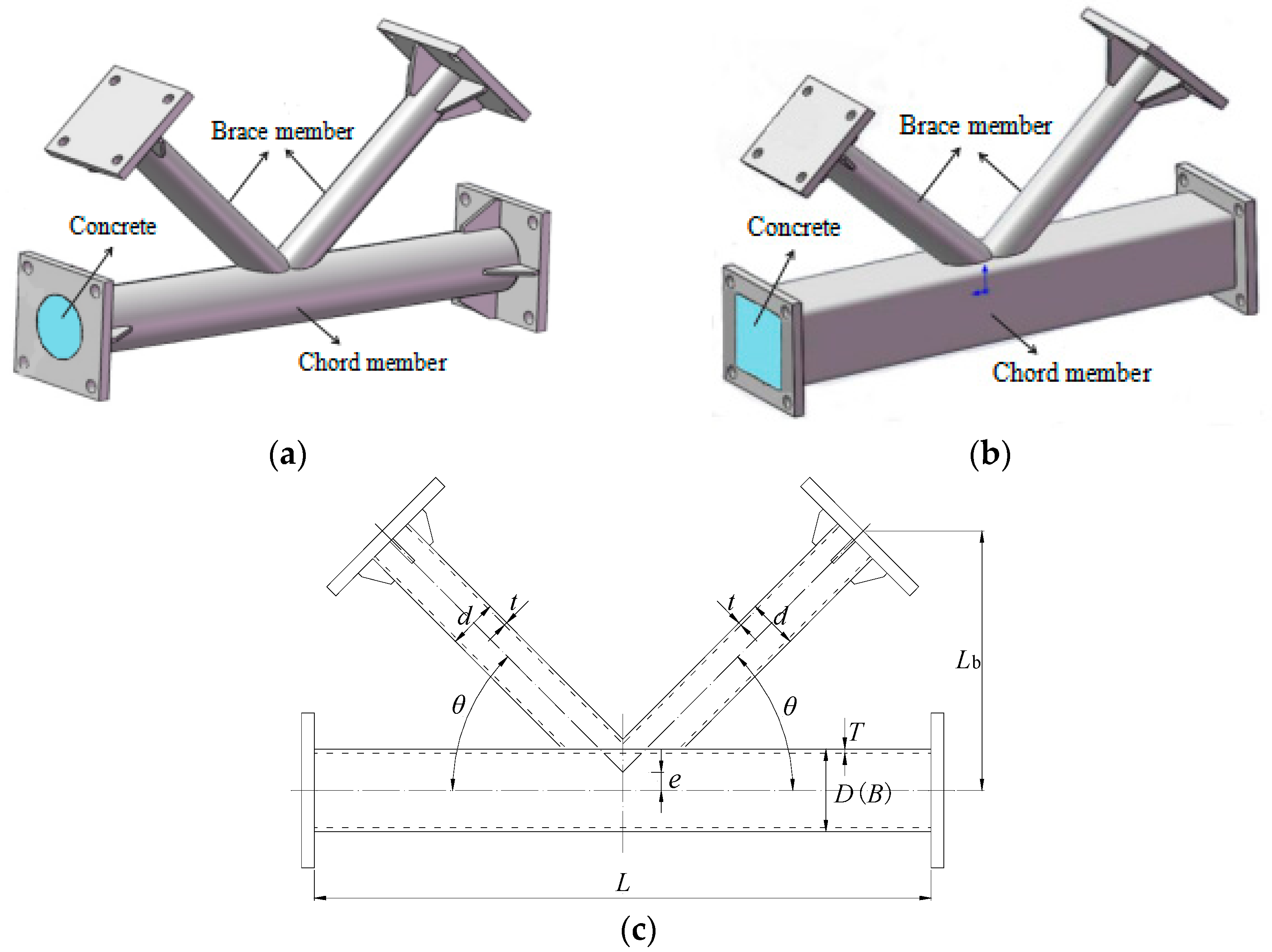
According to the design guidelines given in the Chinese Standard for Design of Steel Structures (GB50017-2017) [43], six K-joint specimens were designed. As shown in Figure 1, “K-RC” denotes the overlapped K-joint with a square chord and circular brace, “K-CC” denotes the overlapped K-joint with circular chord and brace. The geometric parameters of specimens are shown in Table 1. Geometrical dimensions of the chord and brace cross-section were defined as D(B) × T and d × t, respectively. L was the length of chord and brace, and Lb stood for the vertical length of the brace. θ was the angle between the axis of the brace and chord. e was eccentricity, which was the distance between the axis of the chord and the intersection point of the double braces’ axes. In addition to the unstrengthened joints, the overlapped K-joints with chords grouted ordinary concrete (C1) and fly ash concrete (C2) were compared and analyzed. Q345 steel was used in the chords and braces, and the concrete grade was C30. Secondary fly ash was added into fly ash concrete, replacing 30% of the cement content. Additionally, the welds between the brace and chord members were designed and fabricated based on the Chinese national standard for the welding of a steel structure (JGJ81-2002) [44].
2.2. Material Properties
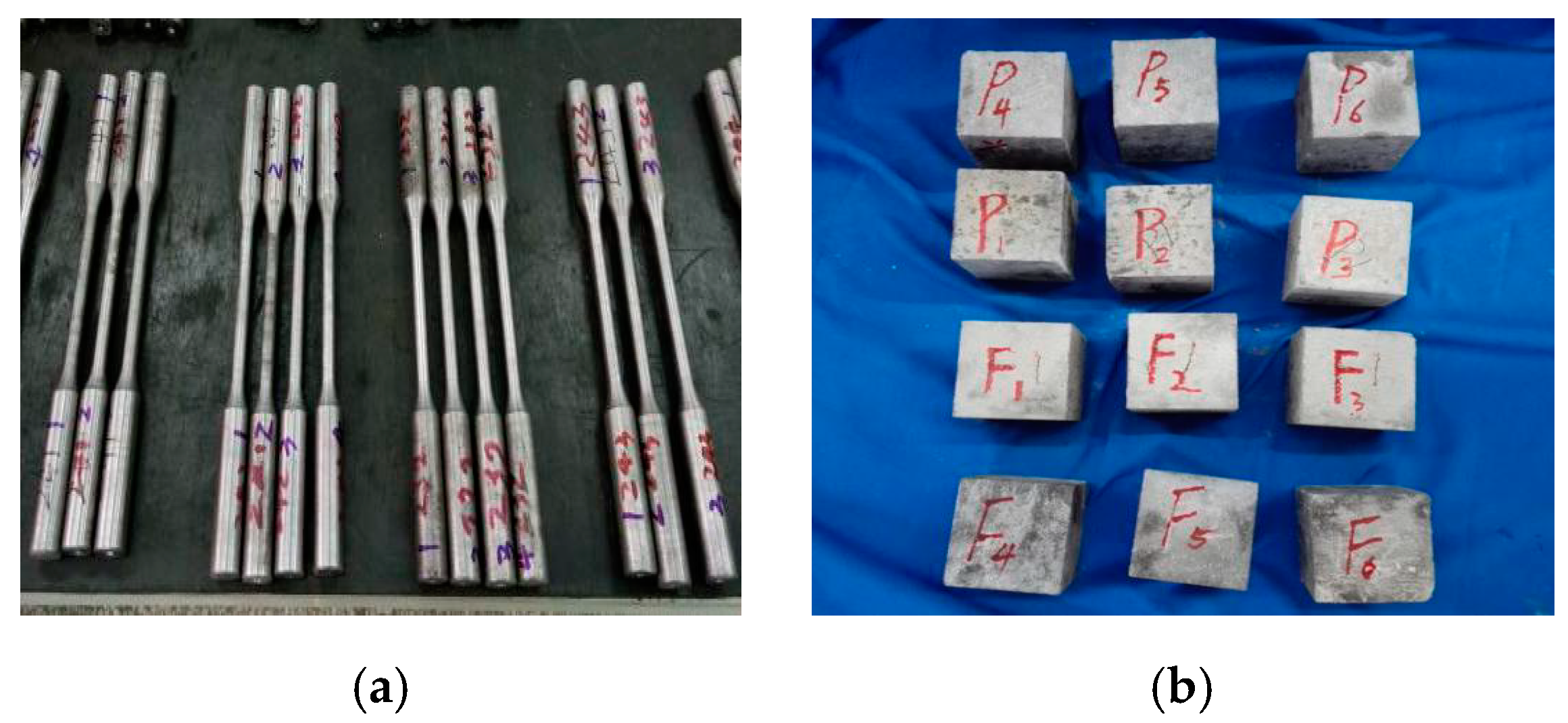
Tensile tests were carried out to determine the mechanical properties of the steel members. The steel with different specifications was made into three standard samples in each group, and then standard samples were tested in a 200 kN capacity testing machine (GL8205, Wuhan, China) according to Chinese Metallic Materials Tensile Testing at Ambient Temperature (GB/T228-2002) [45]. Through the load and strain data recorded by the testing machine, the average values of the three standard samples were calculated. Finally, the results as shown in Table 2 included the yield strength (fy), tensile strength (fu), yield strain (εy), elongation (δ), and elasticity modulus (E). What’s more, the material properties of the concrete cubes with a standard length of 150mm were tested based on the recommendations of the Chinese Standard on Ordinary Concrete (GB/T 50081-2002) [46]. The compressive strength and elastic modulus of ordinary concrete standard cube specimens were 32.78 MPa and 30.12 GPa, respectively, and the compressive strength and elastic modulus of the fly ash concrete standard cube specimens were 30.78 MPa and 29.24 GPa. Figure 2 shows photos of samples that were used to obtain the mechanical properties of the experimental materials.
2.3. Loading Scheme and Test Program
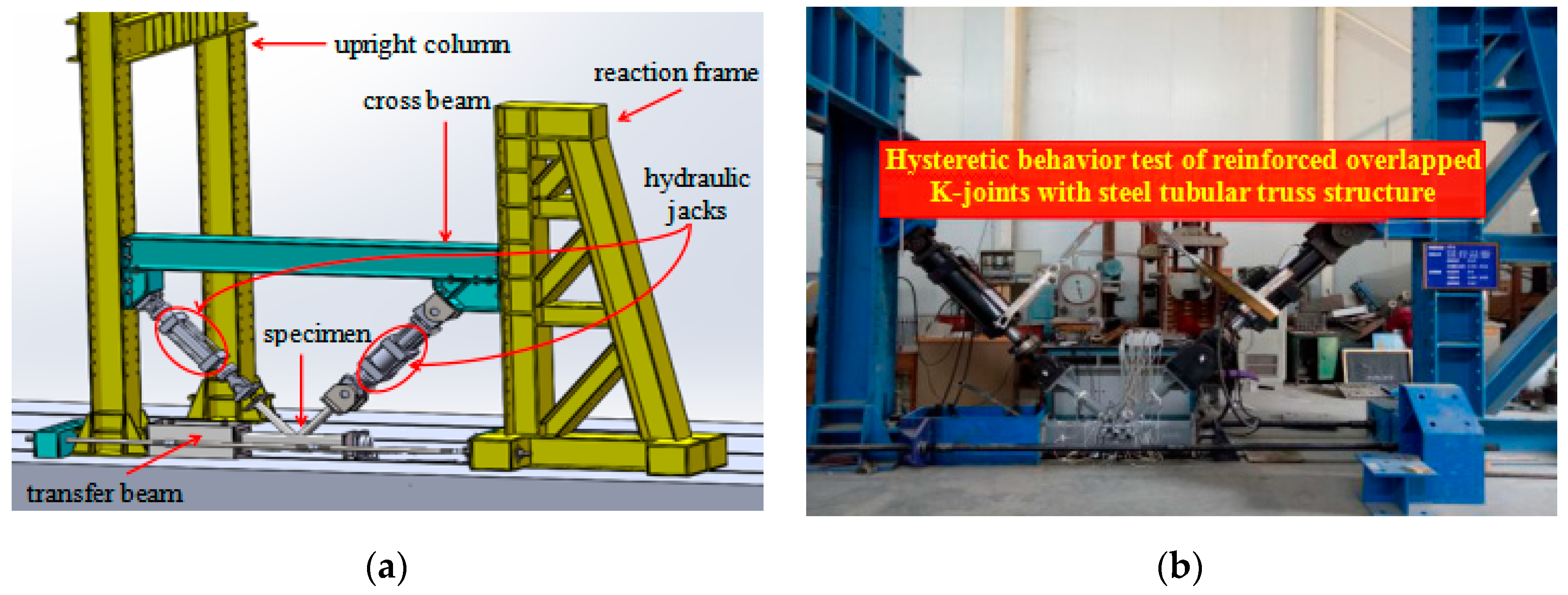
The loading devices used in the test included the reaction frame, upright column, cross beam, transfer beam, test system (DH3861N, DONGHUA, Jiang’su, China), and loading system, as shown in Figure 3. The K-joints were placed in a common plane with the reaction frame, and the left end-plate of the chord was fixed with the transfer beam and the right end-plate was used as a sliding support. Two braces were articulated along their axis with two hydraulic jacks (JSYZ-500, Xi’an Oriental Metal Structure, Xi’an, China) which could provide tension and compression for 500 kN, respectively. The reciprocating load was exerted on the end-plate of the braces by hydraulic jacks. That is, when the through brace was subjected to a compressive load, the overlap brace was controlled to experience an equal magnitude tensile force.
In order to eliminate the installation gap and check whether the instrument was normal, 25% yield load was applied to the joint before formal loading. The force-displacement hybrid loading mode was adopted, and the loading scheme is shown in Figure 4. The formal test loading was divided into two stages: The first stage was controlled by the load, which was divided into three levels, and the increment of each stage was 25% of the yield load and each level load circulated two times. The second stage was controlled by displacement. When the first stage was completed, the displacement △y corresponding to the yield load of the brace was taken as the increment. Each level load circulated three times, until specimen failure.
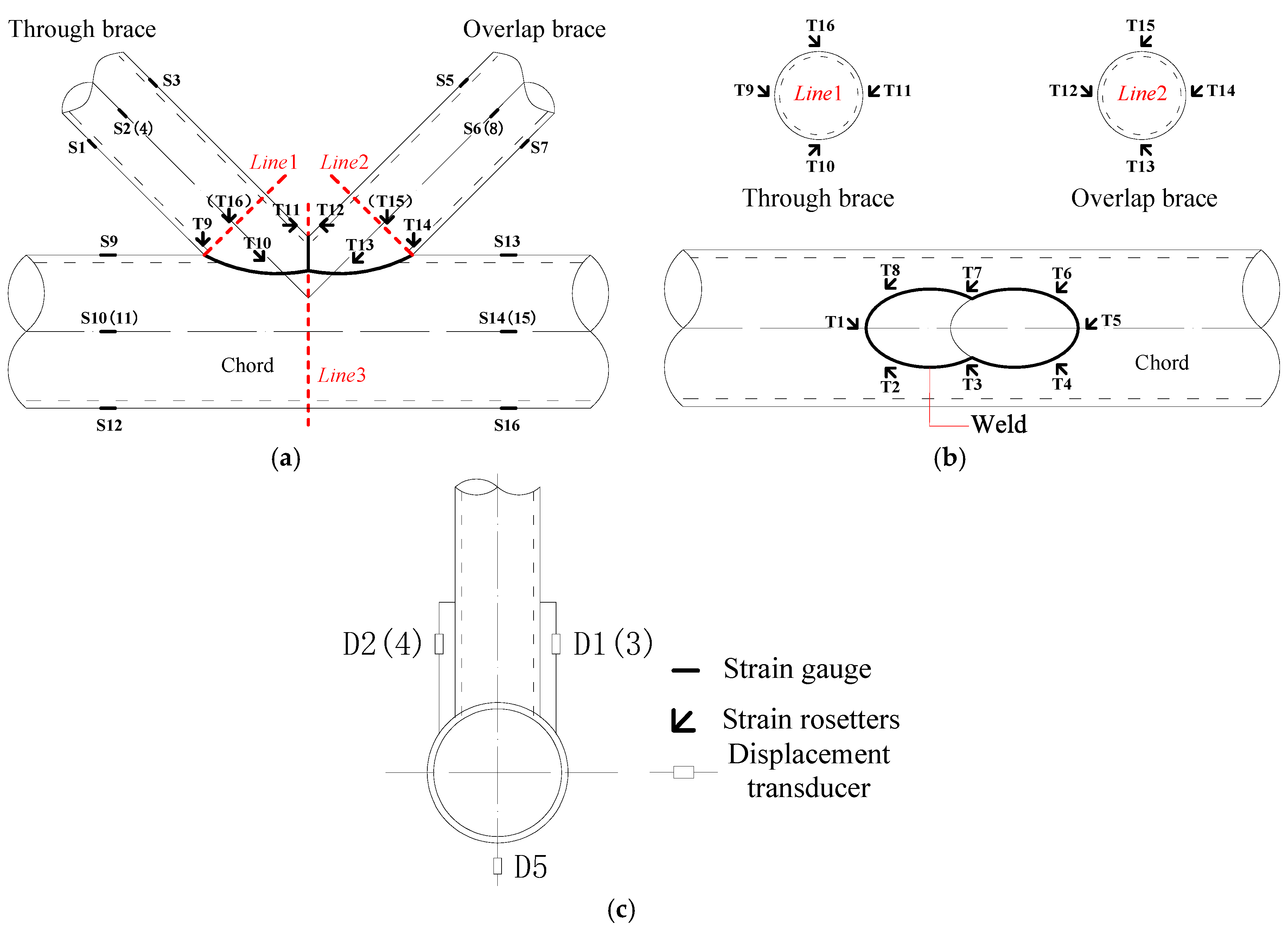
The measurement contents of the test included the reaction force, displacement, local deformation of the joint, stress distribution of the brace and strain distribution of the joint. Each experimental joint setup incorporated five displacement transducers (D050, Jing Ming Technology, Yang’zhou, China), 16 strain gauges and 16 strain rosettes. The layout of the strain gauge and displacement transducer is shown in Figure 5. Each joint was equipped with a strain gauge and T1–T16 strain rosettes to monitor the strain in the complex area of the joint, which was located 20 mm away from the weld, and strain rosettes parallel to the weld lines. S1–S8 strain gauges were attached on the circumferential direction of the through brace and overlap brace and located on a line, 60 mm from parallel line1 and line2, respectively. S9–S16 strain gauges were attached on the circumferential direction of the chord and located on the line 150 mm from the parallel line3. The displacement transducers D1–D4 were used to monitor the deformation of the braces relative to the chord, which was installed on the top surface of the square chord, which was located on line, 50 mm from the parallel line3. The displacement transducer D5 monitored the deformation of the chord’s bottom, which was located on the bottom surface of the square chord or circular chord.
3. Test Results
3.1. Failure Modes
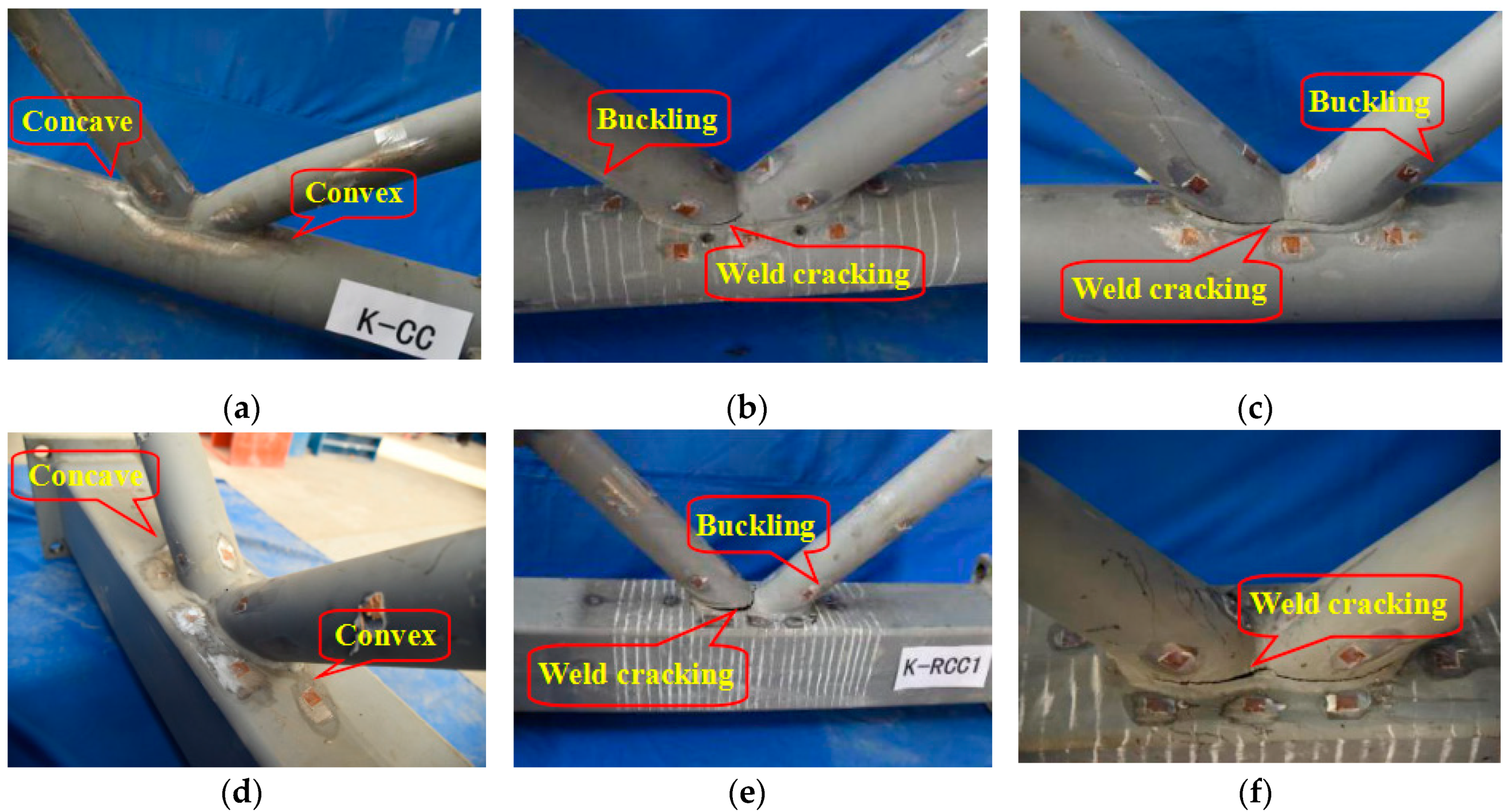
The failure modes of the joints are shown in Figure 6. The joints were in the elastic status before yielding, and there was no obvious deformation of the chords and braces. With the increase of load, the failure modes of the joints were different after yielding. After the K-CC and K-RC joints yield, micro-cracks appeared at the intersection of overlapped braces and the chords. With an increase in the cyclic loading, the unreinforced joint entered the yielding stage. Due to the differing stress state of the through support and the lap joint, the concave and convex deformation occurred on the chord surface, and the plastic deformation of the K-RC joint was more obvious. For the strengthened joints K-CCC1, K-CCC2, K-RCC1 and K-RCC2, the failure modes were similar. After yielding, micro-cracks appeared in the heat-affected zone of the weld seam on the through braces. Then the cracks gradually expanded with an increase in the load, but the plastic deformation of the chord surface was not obvious. Ultimately, the toe weld of the brace was ruptured by tension, and the compressed brace had slight local buckling.
In summary, the main failure mode for the joints without grouting concrete was plastic failure on the surface of the chords; the failure mode of the joints strengthened with concrete in the chord was tension crack failure of the toe weld of the brace, and the compressive brace had slight buckling; the strengthened joints with the different concrete (ordinary concrete and fly ash concrete) in chords had the same failure modes. In general, great changes have taken place in the failure modes of the strengthened joints with grouting concrete in chords. The strengthened measure of grouting concrete in chords effectively improved the mechanical properties of the joints, restrained the plastic deformation of the chord, and avoided the large stress concentration of the chord in the area where the braces and chords intersected.
3.2. Load-Displacement Hysteretic Curve
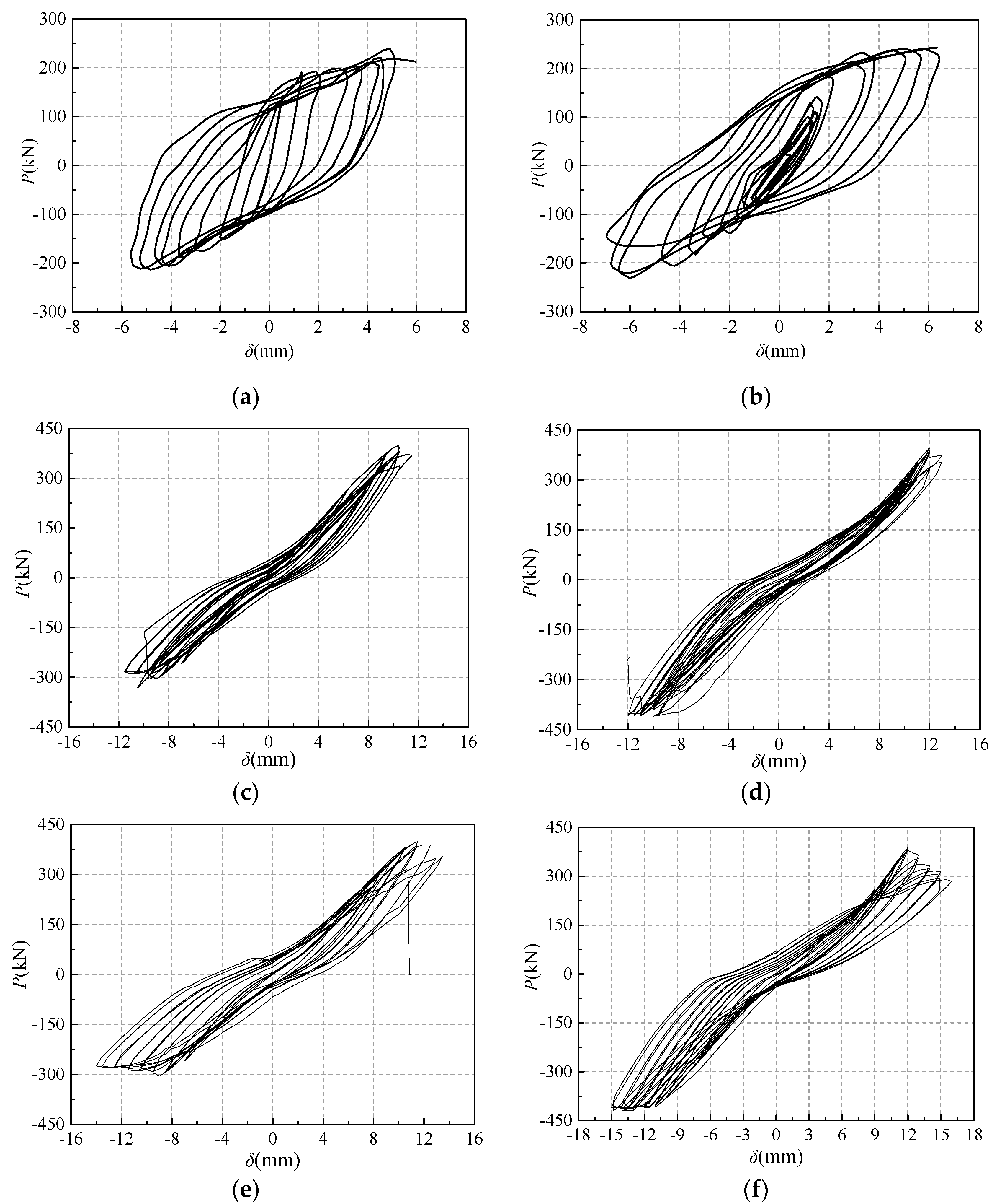
In order to evaluate the seismic capacity of overlapped K-joints under collaborative cyclic loading, the load-displacement curves are plotted in Figure 7, according to the experimental results. Among them, the longitudinal axis was the load P exerted by the hydraulic jack, and the load of the through brace was a positive number in tension and negative number in compression. The transverse axis was the axial displacement δ of the through brace, whose direction was the same as that of P.
The hysteretic curves of K-CC and K-RC joints were fuller than those of the strengthened joints filled with concrete in the chord, and they had a stronger plastic deformation ability and better seismic performance. The tensile and compressive bearing capacity of the unstrengthened joints were basically symmetrical, and the size of the joints were not more than 300 kN. The stiffness of K-CCC1, K-CCC2, K-RCC1 and K-RCC2 joints increased due to grouting concrete in the chord, which restrained the plastic deformation of the chord and improved the bearing capacity. The hysteretic curve was a “flat and thin” shuttle shape. Most of the hysteretic curves were in the elastic stage, and the plastic performance was not obvious. Under the cyclic loading, the cohesive force between the chord and concrete decreased with the cracking of concrete, and a slight deformation appeared on the surface of the chord, and the restraint effect of the chord on the internal concrete was weakened, resulting in the reduction of the joints stiffness. The hysteretic curves of the strengthened joints were a slight “S” type. The hysteretic curve of K-CCC2 was fuller than that of K-CCC1, and that of K-RCC2 was fuller than that of K-RCC1, which showed that the plastic deformation capacity and energy dissipation capacity of the joints strengthened with fly ash concrete filled in chord was slightly better than those of the joints strengthened with ordinary concrete filled in chord. In addition, the hysteresis curve of K-CC was more full than K-RC, and the plastic deformation ability of K-CC was better, but the bearing capacity of the K-RC node was no more than 3% higher than that of the K-CC joint. Because the hoop effect of the circular chord on concrete was more obvious than that of the square chord, the hoop force at the corner of the square chord section was larger than that at the midpoint of the side length, and the hoop force attenuated from the corner to the center of the section. Therefore, the symmetry of the hysteretic loop curve of joints with a circular chord was better.
3.3. Skeleton Curve and Ductility Coefficient
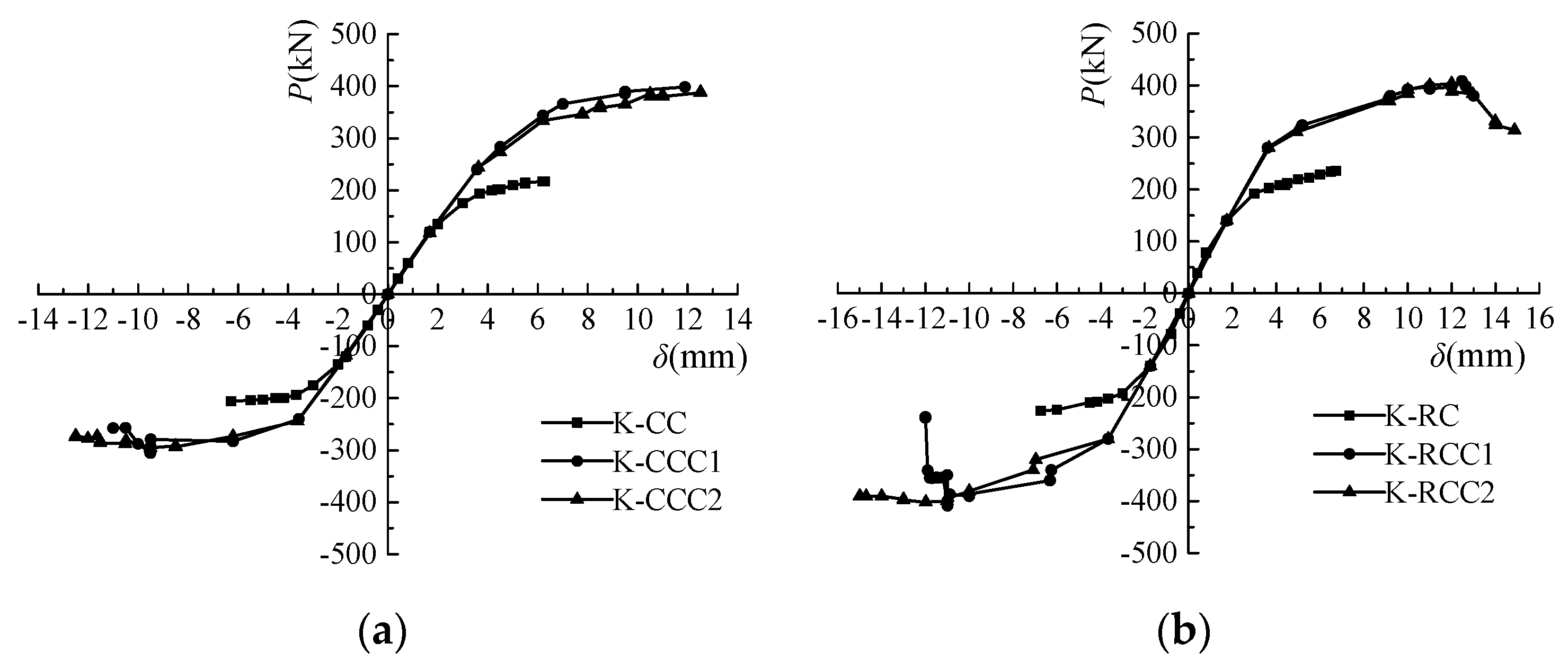
By connecting the peak point of each hysteretic loop, the skeleton curves of the joints were obtained and plotted in Figure 8. It can be seen that the skeleton curve development trend of each joint was basically similar. The strengthening method of grouting concrete in the chord improved the stiffness and bearing capacity of the joints. Compared with the K-CC joint, the ultimate capacity of K-CCC1 and K-CCC2 increased by 71.6% and 67.5%, and the ultimate capacity of K-RCC1 and K-RCC2 was 73.6% and 71.8% higher than that of the corresponding K-RC joint. As far as the section form of the chord was concerned, the bearing capacity of the joint with the circular chord was slightly smaller than that of the joint with the square chord, but no more than 4%, under the same conditions.
Ductility is an important mechanical property index of structure or component. The displacement ductility ratio μ was introduced to assess the deformation capacity of the joints. The ductility coefficient μ was defined as δu/δy, δu and δy and were the ultimate displacements and the yield displacement of the joint appearing in the skeleton curve. The ductility coefficients of the joints are shown in Table 3. It can be seen that the yield displacement of K-CCC1 and K-CCC2 were both about 2.2 times that of the K-CC joint, and the yield displacement of K-RCC1 and K-RCC2 were both about 2.1 times that of the K-RC joint. The ultimate displacement of the strengthened joints was obviously increased because the chord was filled with concrete. On the whole, the ductility coefficients of the unstrengthened joints were higher than those of strengthened joints, which showed that the ductility of the joint was weakened to a certain extent, although the bearing capacity of the joint was effectively improved by concrete filling in the chord. The ductility of the strengthened joint with fly ash concrete filled in the chord was better than that of the reinforced joint with ordinary concrete filled in the chord.
3.4. Energy Dissipation Analysis
In order to quantitatively evaluate the energy dissipation capacity of the joints, the energy dissipation ratio η, accumulative energy dissipation Usum and maximum hysteretic loop energy dissipation U were introduced, which were defined in Equations (1)–(3). Among them, Ui represented the area enveloped by each hysteretic loop of the joint. Usum indicated the total area of all hysteretic loops. Energy dissipation ratio η was based on accumulative energy dissipation Usum and hysteretic loop energy dissipation Ui, considered the elastic potential energy of each hysteretic loop, which could more accurately reflect the energy dissipation capacity of the joints. Additionally, , , and represented the yield load and yield displacement of the joints under positive and negative loading, respectively. The energy dissipation evaluation parameters for the joints are shown in Table 4.
As can be seen from Table 4, the maximum hysteretic loop energy dissipation of K-CCC1 and K-CCC2 was 6.8% and 74.0% higher than that of the corresponding K-CC joint. Compared with the K-RC joint, the maximum hysteretic loop energy dissipation of K-RCC1 and K-RCC2 increased by 6.3% and 54.5%. In terms of Usum, the accumulative energy dissipation of the strengthened joints was obviously higher than those of unstrengthened joints. The strengthening measure of grouting concrete in the chord could effectively improve the bearing capacity of joints, which contributes to the increase of accumulative energy dissipation Usum and maximum hysteretic loop energy dissipation U. On the contrary, the energy dissipation ratios of strengthened joints were obviously smaller than those of unstrengthened joints. For example, the energy dissipation ratios of K-CCC1 and K-CCC2 was 132.3% and 81.2% smaller than that of the K-CC joint, and the energy dissipation ratio of K-RC was approximately three times and two times that of K-RCC1 and K-RCC2. The changing trend of the energy dissipation parameters of the above joints showed that grouting concrete in the chord improved the radial stiffness of the chord, restrained the plastic deformation of the chord and weakened the plastic energy dissipation capacity of the joint to a certain extent, so that the energy dissipation ratio of the unstrengthened joints relying on plastic deformation was larger than the strengthened joints. What’s more, the energy dissipation ratio, accumulative energy dissipation and maximum hysteretic loop energy dissipation of the joint strengthened with grouting fly ash concrete in a chord were all higher than those of the joint strengthened with grouting ordinary concrete in the chord.
4. Finite Element Analysis
4.1. Establishment of a Finite Element Model
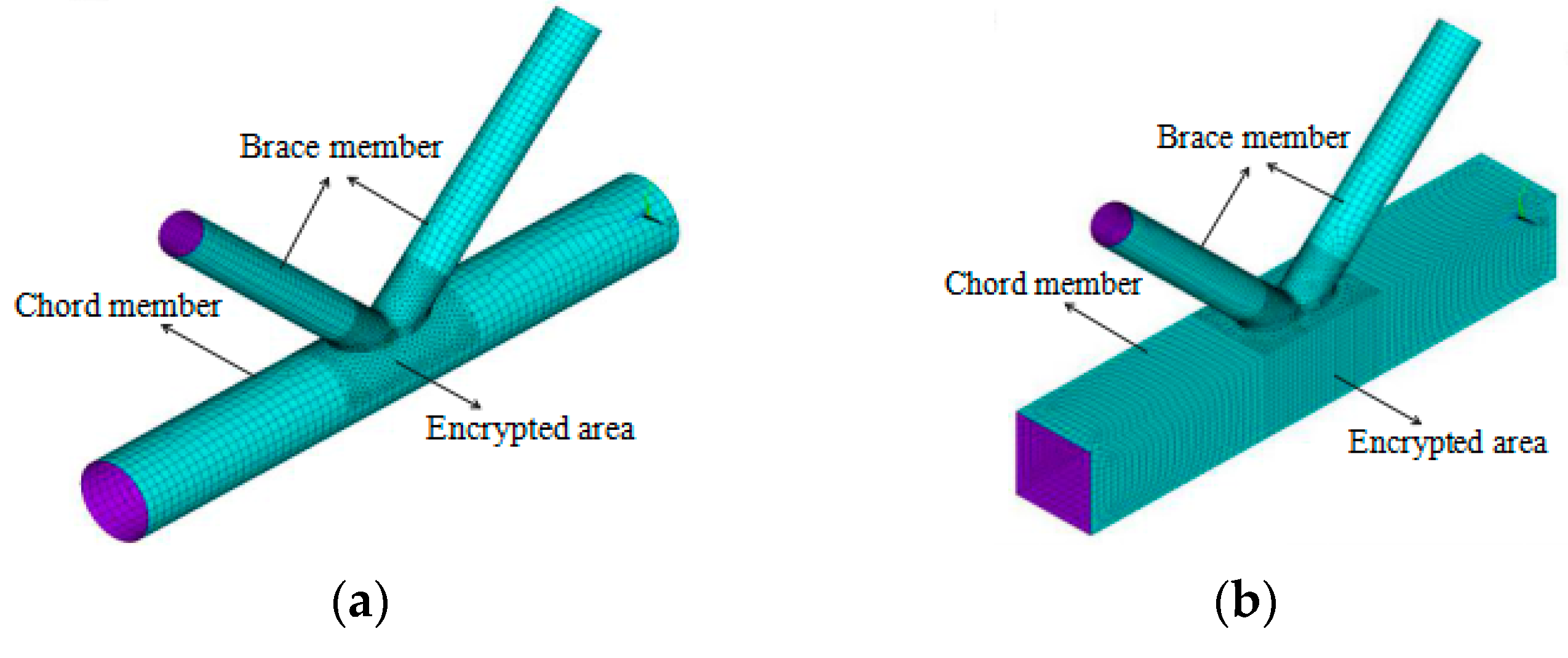
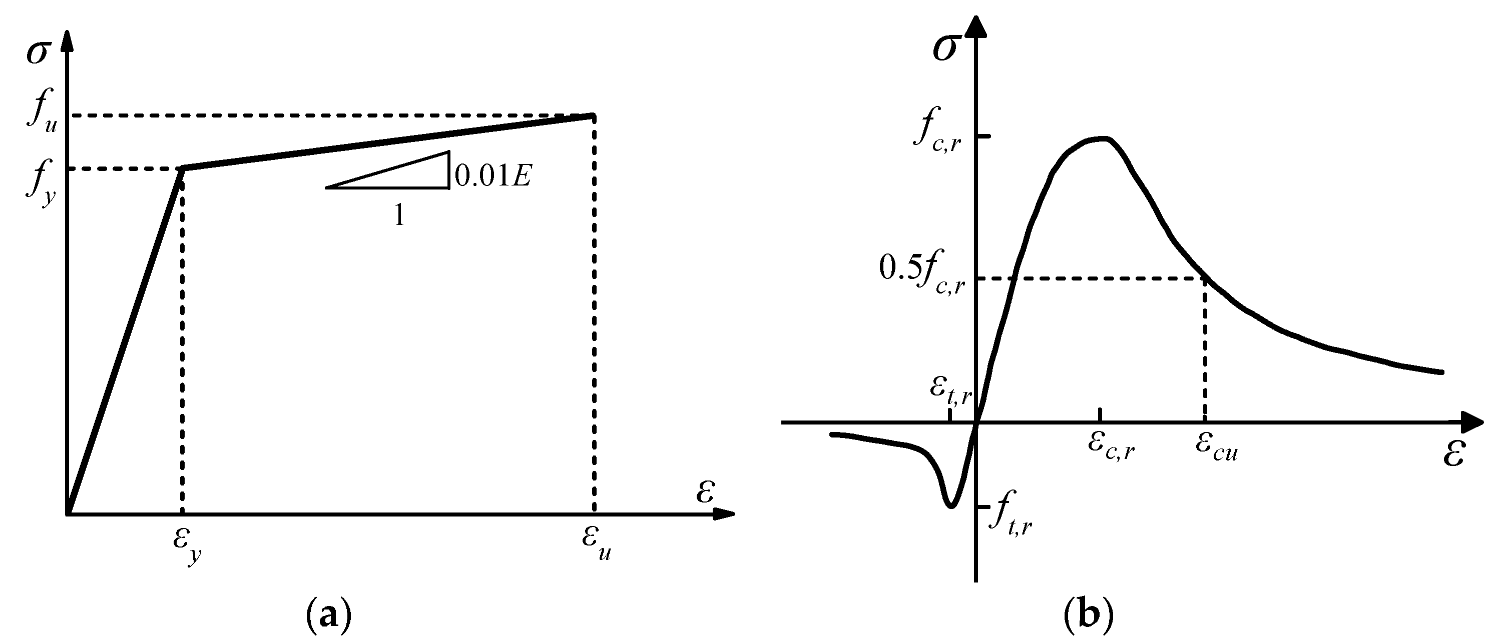
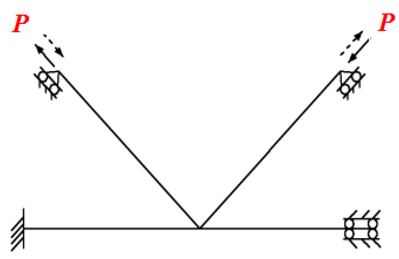
The hysteretic behavior of the overlapped K-joints was simulated by finite element software ANSYS [47] (ANSYS 10.0, ANSYS-Inc., Pittsburgh, PA, USA, 2006). The load-displacement nonlinear analysis was performed by using the full Newton-Raphson iteration method. In addition, the nonlinear characteristics of materials and geometry were taken into consideration in the finite element models. The three-dimensional four-node elastic-plastic Shell181 was used to simulate the steel tubes, and the Solid65 element was applied concrete. What’s more, the encrypted area was divided freely in the model, and the non-encrypted area was divided by mapping. The finite element model is shown in Figure 9. As shown in Figure 10, the boundary conditions of the model were the same as those of the test, that is, one end of the chord was a fixed constraint, the other end could be sliding in a specific direction, and the two end-plate of the brace was hinged. As shown in Figure 11, a bilinear kinematic hardening model (BKIN) was adopted for steel, which included an elastic stage and a strengthening stage, and the modulus magnitude of the strengthening stage was 1% that of the elastic stage, in accordance with Shao et al. [42]. Poisson’s ratio (ν) of the steel was 0.3. Elastic modulus (E) and yield strength (fy) were measured with a material property test. A Multilinear isotropic hardening model (MISO) was used for concrete. Poisson’s ratio was 0.2 and the elastic modulus of concrete came from experimental values. Surface-to-Surface contact pairs were established between the chord and concrete. The concrete surface was the target surface, the inner surface of the chord was the contact surface, and the friction coefficient was 0.3.
4.2. Weld Modeling
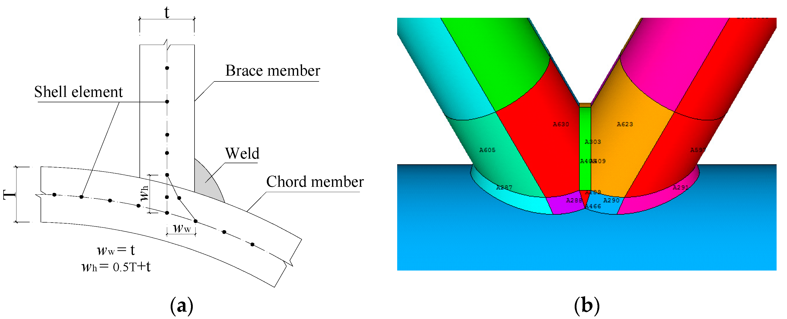
Weld modeling has seldom been taken into consideration in the finite element analysis. However, it was found that if the effect of the weld was not considered, the numerical simulations of load carrying capacity and joint rigidity were smaller than those of the experimental results [48]. In this study, element Shell181 was used for weld modeling by way of adding a circle of Shell181 around the intersection of the brace and chord members. It should be noted that the contact element was used for simulating the case of hidden weld unwelded. The weld modeling is shown in Figure 12.
4.3. The Result Analysis of test and finite element
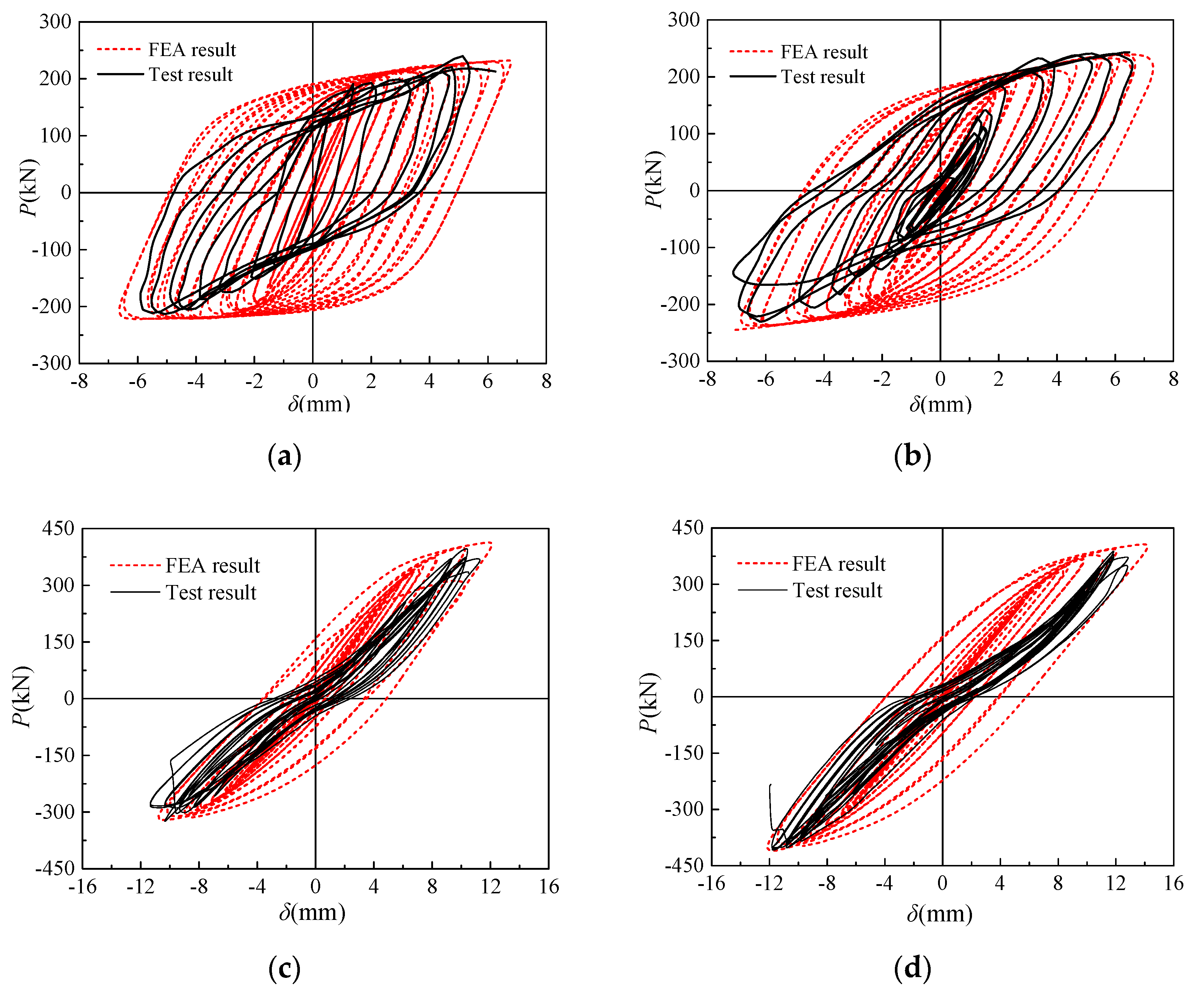
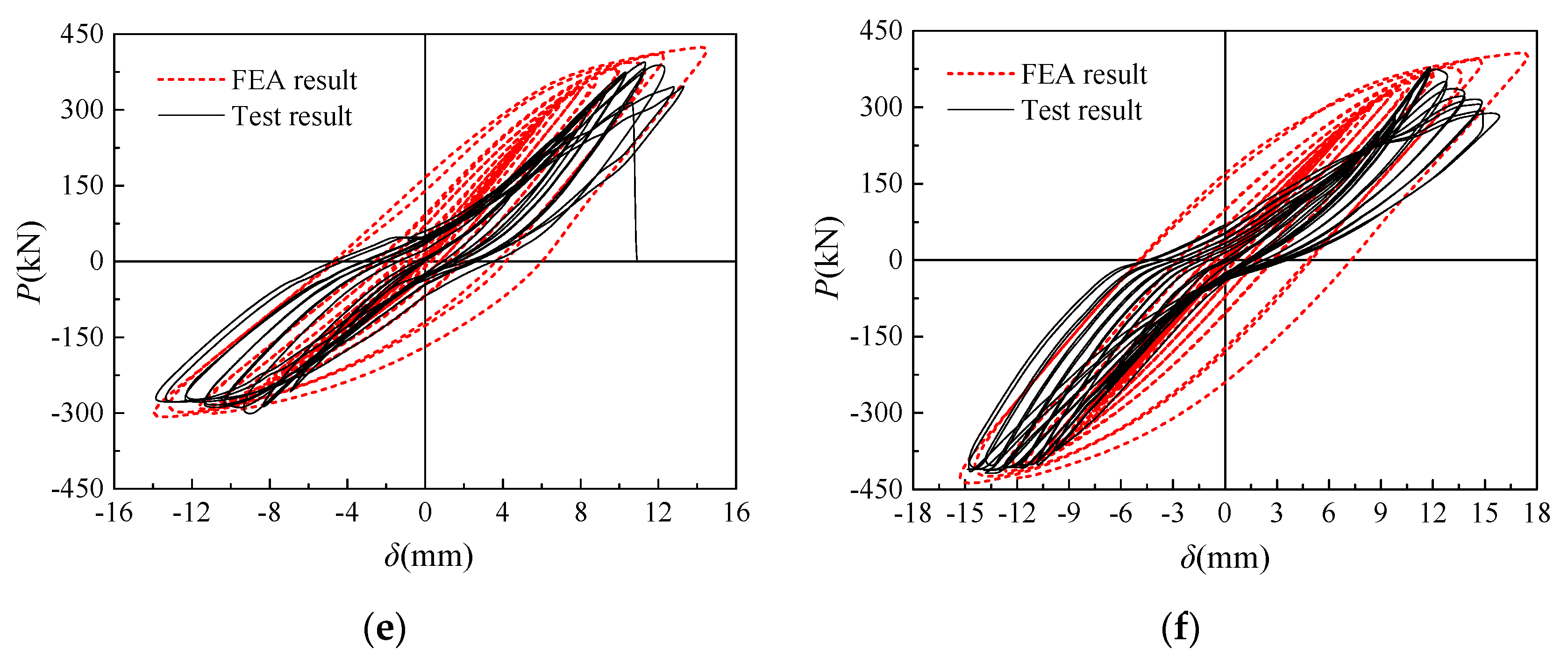
As shown in Figure 13, the hysteresis curve of the finite element analysis was more full with a “shuttle” shape and the plastic deformation ability was better than the experimental results, but the overall fit was good. It can be seen from Table 5 that the difference between the finite element results and the test results was not more than 10%. The major reasons for the difference were that the finite element model of the joint did not consider the initial defects and material damage, and the material constitutive model used in the finite element model was idealized, which cannot completely reflect the material state in the actual test. Although the above factors led to errors between the finite element analysis results and the test results, the errors were within the allowable range, which showed that the analysis applying finite element software ANSYS was accurate and reasonable for this kind of overlapped K-joints.
5. Conclusions and Future Work
The overlapped K-joints were strengthened by grouting concrete in the chord. Six K-joints including the joint with a circular chord and brace and the joint with a square chord and circular brace, were designed to carry out a quasi-static test and numerical simulation. The failure modes, hysteretic curves, skeleton curves, ductility coefficient, and energy dissipation ratio of the joints were obtained. The hysteretic performance, ductility, and energy dissipation capacity of the joints were evaluated quantitatively. The following conclusions were drawn from this research:
(1) Under the cyclic loading, the major failure mode of the overlapped K-joints without strengthening was plastic failure of the chord; while the failure mode of the joints strengthened with concrete in the chord was tension crack failure of the toe weld of the brace. The compressive brace had slight buckling, which could dissipate some energy. The failure modes of strengthened K-joints with ordinary concrete and fly ash concrete were basically the same.
(2) Compared with the unstrengthened K-joints, the ductility and energy dissipation ratio of the strengthened K-joints were reduced to a certain extent, however the strengthening measure with concrete significantly enhanced the bearing capacity of the K-joints, delayed the plastic development of the chord and improved the mechanical properties of the K-joints.
(3) The hysteretic behavior of the K-joints with the circular chord and brace was slightly better than that of the K-joints with a square chord and circular brace. The hysteretic behavior of the K-joints strengthened with fly ash concrete was better than that of the K-joints strengthened with ordinary concrete. The ductility and energy dissipation ratio of the K-joints strengthened with fly ash concrete were superior to that of the K-joints strengthened with ordinary concrete. Based on the above conclusions, it was feasible to use fly ash instead of ordinary concrete to strengthen the K-joints partly.
(4) The numerical simulation of six K-joints specimens under reciprocating loading was carried out by ANSYS, and the results were in good agreement with the test results, which showed that the numerical simulation analysis model and method established in this paper was feasible.
In the current research, the effect of corrosion was not considered. It is well known that chloride diffusion plays an import role in corrosion in both steel and concrete structures [49,50,51]. One area of our future work is to consider corrosion in the study of hysteretic behavior of the overlapped K-joints with the concrete filled in chord. Using piezoceramic transducers, scholars have conducted research on damage detection of concrete structures [52,53], especially in concrete filled tubular structures [54,55,56]. In future work, the authors will explore the health monitoring of the K-joints with concrete filled in chord by using piezoceramic transducers.
Author Contributions
W.Y. incepted the original idea and designed the experiment. G.Z. analyzed the data. R.Y., Y.S., and B.H. wrote the paper. W.Y. revised the paper.
Funding
This research was supported in part by the National Natural Science Foundation of China (Nos. 51468054) and in part by the Funding Project of First-Class Discipline Construction of Universities in Ningxia (Domestic First-Class Discipline Construction) under Grant NXYLXK2017A03.
Conflicts of Interest
The authors declare no conflicts of interest.
References
- Jiang, T.; Wu, Q.; Wang, L.; Huo, L.; Song, G. Monitoring of Bolt Looseness-induced Damage in Steel Truss Arch Structure using Piezoceramic Transducers. IEEE Sens. J. 2018, 18, 6677–6685. [Google Scholar] [CrossRef]
- Tiainen, T.; Mela, K.; Jokinen, T.; Heinisuo, M. The effect of steel grade on weight and cost of warren-type welded tubular trusses. Proc. Inst. Civ. Eng. Struct. Build. 2017, 170, 855–873. [Google Scholar] [CrossRef]
- Gillman, A.; Fuchi, K.; Buskohl, P.R. Truss-based nonlinear mechanical analysis for origami structures exhibiting bifurcation and limit point instabilities. Int. J. Solids Struct. 2018, 147, 80–93. [Google Scholar] [CrossRef]
- Wardenier, J.; Packer, J.A.; Zhao, X.L.; Van der Vegte, G.J. Hollow Sections in Structural Applications; CIDECT: Geneva, Switzerland, 2010. [Google Scholar]
- Han, L.-H. Some recent developments of concrete filled steel tubular (CFST) structures in China. In Proceedings of the 4th International Conference on Steel & Composite Structures 2010, Sydney, Australia, 21–23 July 2010; pp. 43–54. [Google Scholar]
- Wu, Q.; Yoshimura, M.; Takahashi, K.; Nakamura, S.; Nakamura, T. Nonlinear seismic properties of the Second Saikai Bridge: A concrete filled tubular (CFT) arch bridge. Eng. Struct. 2006, 28, 163–182. [Google Scholar] [CrossRef]
- Zhao, X.; Liu, J.; Xu, X.; Sivakumaran, K.S.; Chen, Y. Hysteretic behaviour of overlapped tubular k-joints under cyclic loading. J. Constr. Steel Res. 2018, 145, 397–413. [Google Scholar] [CrossRef]
- Wang, X.L.; Yang, W.W.; Zou, L. Finite Element Analysis for Unstiffened Overlapped CHS K-Joints Welded in Different Ways. Adv. Mater. Res. 2011, 163–167, 299–306. [Google Scholar]
- Wang, X.L.; Chen, P.; Yang, W.W. Finite Element Analysis for Unstiffened Overlapped CHS KK-Joints Welded in Different Ways. Adv. Mater. Res. 2011, 446–449, 533–536. [Google Scholar] [CrossRef]
- Yang, W.; Wang, X. Numerical analysis of hysteretic behavior of unstiffened overlapped CHS K-Joints in steel pipe structures by finite element method. J. Lanzhou Univ. Technol. 2012, 33, 009. [Google Scholar]
- Yang, W.; Wang, X. Experimental research on seismic behavior of unstiffened overlapped CHS K-Joints. J. Build. Struct. 2013, 34, 85–92. [Google Scholar]
- Zhang, L.; Li, Z.; Cheng, M. Concrete-Filled Steel Tubular Truss Girders as Bridge Structures; People Communication Press: Beijing, China, 2000. (In Chinese) [Google Scholar]
- Chen, B.; Wang, T.-L. Overview of concrete filled steel tube arch bridges in China. Practice periodical on structural design and construction. ASCE 2009, 14, 70–80. [Google Scholar]
- Song, G.; Vlattas, J.; Johnson, S.E.; Agrawal, B.N. Active vibration control of a space truss using a lead zirconate titanate stack actuator. Proc. Inst. Mech. Eng. Part G J. Aerosp. Eng. 2001, 215, 355–361. [Google Scholar] [CrossRef]
- Han, L.H.; Zheng, L.Q.; He, S.H.; Tao, Z. Tests on curved concrete filled steel tubular members subjected to axial compression. J. Constr. Steel Res. 2011, 67, 965–976. [Google Scholar] [CrossRef]
- Xue, J.Q.; Briseghella, B.; Chen, B.C. Effects of debonding on circular CFST stub columns. J. Constr. Steel Res. 2012, 69, 64–76. [Google Scholar] [CrossRef]
- Ding, F.X.; Luo, L.; Wang, L.; Cheng, S.; Yu, Z.W. Pseudo-static tests of terminal stirrup-confined concrete-filled rectangular steel tubular columns. J. Constr. Steel Res. 2018, 144, 135–152. [Google Scholar] [CrossRef]
- Qian, X.D.; Choo, Y.S.; Liew, J.Y.R.; Wardenier, J. Static Strength of Thick-Walled CHS X-Joints Subjected to Brace Moment Loadings. J. Struct. Eng. 2007, 133, 1278–1287. [Google Scholar] [CrossRef]
- Patel, V.I.; Hassanein, M.F.; Thai, H.T.; Al Abadi, H.; Elchalakani, M.; Bai, Y. Ultra-high strength circular short CFST columns: Axisymmetric analysis, behaviour and design. Eng. Struct. 2019, 179, 268–283. [Google Scholar] [CrossRef]
- Du, G.; Zhang, J.; Zhang, J.; Song, G. Experimental Study on Stress Monitoring of Sand-Filled Steel Tube during Impact Using Piezoceramic Smart Aggregates. Sensors 2017, 17, 1930. [Google Scholar] [CrossRef]
- Du, G.; Li, Z.; Song, G. A PVDF-Based Sensor for Internal Stress Monitoring of a Concrete-Filled Steel Tubular (CFST) Column Subject to Impact Loads. Sensors 2018, 18, 1682. [Google Scholar] [CrossRef]
- Huang, Q.; Xu, B.; Li, B.; Song, G.; Teng, J. Monitoring for Large Cross-Section CFSTs of a Super High-Rise Building with Piezoceramic Actuators and Sensors. Adv. Mater. Res. 2011, 163–167, 2553–2559. [Google Scholar] [CrossRef]
- International Institute of Welding (IIW). Static Design Procedure for Welded Hollow Section Joints-Recommendations, Doc. XV-1402-12, 3rd ed.; International Institute of Welding: Paris, France, 2012. [Google Scholar]
- Zhao, X.Z.; Chen, Y.; Chen, Y.Y.; Wang, G.N.; Xu, L.X.; Zhang, R.Q. Experimental study on static behavior of unstiffened overlapped CHS K-joints. J. Build. Struct. 2006, 27, 23–29. (In Chinese) [Google Scholar]
- Sakai, Y.; Hosaka, T.; Isoe, A.; Ichikawa, A.; Mitsuki, K. Experiments on concrete filled and reinforced tubular K-joints of truss girder. J. Constr. Steel Res. 2004, 60, 683–699. [Google Scholar] [CrossRef]
- Xu, W.; Han, L.-H.; Tao, Z. Flexural behaviour of curved concrete filled steel tubular trusses. J. Constr. Steel Res. 2014, 93, 119–134. [Google Scholar] [CrossRef]
- Chen, Y.; Feng, R.; Xiong, L. Experimental and numerical investigations on double-skin CHS tubular X-joints under axial compression. Thin-Walled Struct. 2016, 106, 268–283. [Google Scholar] [CrossRef]
- Hou, C.; Han, L.-H.; Mu, T.-M. Behaviour of CFDST chord to CHS brace composite K-joints: Experiments. J. Constr. Steel Res. 2017, 135, 97–109. [Google Scholar] [CrossRef]
- Feng, R.; Young, B. Tests of concrete-filled stainless steel tubular T-joints. J. Constr. Steel Res. 2008, 64, 1283–1293. [Google Scholar] [CrossRef]
- Feng, R.; Chen, Y.; Wei, J.; He, K.; Fu, L. Behaviour of grouted stainless steel tubular X-joints with CHS chord under axial compression. Thin-Walled Struct. 2018, 124, 323–342. [Google Scholar] [CrossRef]
- Lesani, M.; Bahaari, M.; Shokrieh, M. Detail investigation on un-stiffened T/Y tubular joints behavior under axial compressive loads. J. Constr. Steel Res. 2013, 80, 91–99. [Google Scholar] [CrossRef]
- Ju, Y.; Wang, D. Nonlinear finite element analysis of the ultimate strength of tubeangle combo tower K-joints. Strength Mater. 2015, 47, 355–361. [Google Scholar] [CrossRef]
- Lv, B.H.; Chen, Z.Q.; Li, H.; Guan, S.Q.; Li, X.L.; Zhang, L. Research on the ultimate bearing capacity for steel tubular transmission tower’s joints with annular plate. Appl. Mech. Mater. 2012, 166–169, 379–384. [Google Scholar] [CrossRef]
- Rong, Z.J.; Wang, X.M.; Lv, B.H.; Zhang, X.Y.; Zhang, L. Theoretical analysis on the ultimate bearing capacity for steel tubular transmission tower’s joints with annular plate. Appl. Mech. Mater. 2014, 664, 175–181. [Google Scholar] [CrossRef]
- Qian, X.; Zhang, Y.; Choo, Y.S. A load-deformation formulation for CHS X-and K-joints in push-over analyses. J. Constr. Steel Res. 2013, 90, 108–119. [Google Scholar] [CrossRef]
- Yin, Y.; Han, Q.H.; Bai, L.J.; Yang, H.D.; Wang, S.P. Experimental Study on hysteretic behaviour of tubular N-joints. J. Constr. Steel Res. 2009, 65, 326–334. [Google Scholar] [CrossRef]
- Xu, F.; Chen, J.; Jin, W.L. Experimental investigation of SCF distribution for thin-walled concrete-filled CHS joints under axial tension loading. Thin-Walled Struct. 2015, 93, 149–157. [Google Scholar] [CrossRef]
- Qian, X.; Jitpairod, K.; Marshall, P.; Swaddiwudhipong, S.; Ou, Z.; Zhang, Y.; Pradana, M.R. Fatigue and residual strength of concrete-filled tubular X-joints with full capacity welds. J. Constr. Steel Res. 2014, 100, 21–35. [Google Scholar] [CrossRef]
- Tong, L.W.; Xu, G.W.; Yang, D.L.; Mashiri, F.R.; Zhao, X.L. Fatigue behavior and design of welded tubular T-joints with CHS brace and concrete-filled chord. Thin-Walled Struct. 2017, 120, 180–190. [Google Scholar] [CrossRef]
- Lee, M.M.K.; Llewelyn-Parry, A. Strength prediction for ring-stiffened DT-joints in offshore jacket structures. Eng. Struct. 2005, 27, 421–430. [Google Scholar] [CrossRef]
- Xia, J.; Chang, H.; Goldsworthy, H.; Bu, Y.; Lu, Y. Axial hysteretic behavior of doubler-plate reinforced square hollow section tubular T-joints. Mar. Struct. 2017, 55, 162–181. [Google Scholar] [CrossRef]
- Shao, Y.B.; Li, T.; Seng, T.L.; Chiew, S.P. Hysteretic behaviour of square tubular T-joints with chord reinforcement under axial cyclic loading. J. Constr. Steel Res. 2011, 67, 140–149. [Google Scholar] [CrossRef]
- Chinese Code. GB/50017-2017 Standard for Design of Steel Structures; Standards Press of China: Beijing, China, 2017. [Google Scholar]
- Chinese Code. Jgj81-2002 Technical Specification for Welding of Steel Structure of Building; Standards Press of China: Beijing, China, 2003. [Google Scholar]
- Chinese Code. Gb/T 228-2002 Metallic Materials-Tensile Testing at Ambient Temperature; Standards Press of China: Beijing, China, 2002. [Google Scholar]
- Chinese Code. Gb/T50081-2002 Test Method of Mechanical Properties on Ordinary Concrete; Standards Press of China: Beijing, China, 2003. [Google Scholar]
- ANSYS-Inc. ANSYS Structural Analysis Guide. 2004. Available online: http://www.ansys.stuba.sk/html/guide_55/g-str/GSTRToc.htm (accessed on 1 November 2018).
- Vegte, G.J.V.D. The Static Strength of Uniplanar and Multiplanar Tubular T- and X-Joints; Delft University Press: Delft, The Netherlands, 1995. [Google Scholar]
- Peng, J.; Hu, S.; Zhang, J.; Cai, C.S.; Li, L.Y. Influence of cracks on chloride diffusivity in concrete: A five-phase mesoscale model approach. Constr. Build. Mater. 2019, 197, 587–596. [Google Scholar] [CrossRef]
- Du, G.; Kong, Q.; Zhou, H.; Gu, H. Multiple cracks detection in pipeline using damage index matrix based on piezoceramic transducer-enabled stress wave propagation. Sensors 2017, 17, 1812. [Google Scholar] [CrossRef]
- Li, W.; Xu, C.; Ho, S.; Wang, B.; Song, G. Monitoring concrete deterioration due to reinforcement corrosion by integrating acoustic emission and FBG strain measurements. Sensors 2017, 17, 657. [Google Scholar] [CrossRef]
- Kong, Q.; Robert, R.; Silva, P.; Mo, Y. Cyclic crack monitoring of a reinforced concrete column under simulated pseudo-dynamic loading using piezoceramic-based smart aggregates. Appl. Sci. 2016, 6, 341. [Google Scholar] [CrossRef]
- Xu, K.; Ren, C.; Deng, Q.; Jin, Q.; Chen, X. Real-time monitoring of bond slip between GFRP bar and concrete structure using piezoceramic transducer-enabled active sensing. Sensors 2018, 18, 2653. [Google Scholar] [CrossRef]
- Luo, M.; Li, W.; Hei, C.; Song, G. Concrete Infill Monitoring in Concrete-Filled FRP Tubes Using a PZT-Based Ultrasonic Time-of-Flight Method. Sensors 2016, 16, 2083. [Google Scholar] [CrossRef]
- Zhang, J.; Li, Y.; Du, G.; Song, G. Damage Detection of L-Shaped Concrete Filled Steel Tube (L-CFST) Columns under Cyclic Loading Using Embedded Piezoceramic Transducers. Sensors 2018, 18, 2171. [Google Scholar] [CrossRef]
- Xu, Y.; Luo, M.; Hei, C.; Song, G. Quantitative evaluation of compactness of concrete-filled fiber-reinforced polymer tubes using piezoceramic transducers and time difference of arrival. Smart Mater. Struct. 2017, 27, 035023. [Google Scholar] [CrossRef]
Figure 1.
Design diagram of specimens. (a) Model diagram of K-CC (The K-joint with circular chord and brace); (b) Model diagram of K-RC (The K-joint with a square chord and circular brace); (c) Basic parameters of specimens.
Figure 1.
Design diagram of specimens. (a) Model diagram of K-CC (The K-joint with circular chord and brace); (b) Model diagram of K-RC (The K-joint with a square chord and circular brace); (c) Basic parameters of specimens.

Figure 2.
Samples of experimental materials. (a) The standard specimens of Q345; (b) The standard specimens of concrete.
Figure 2.
Samples of experimental materials. (a) The standard specimens of Q345; (b) The standard specimens of concrete.

Figure 3.
Loading device. (a) Design drawing of test loading device; (b) The test site.

Figure 4.
Loading device for cyclic loading.

Figure 5.
Layout of measuring points. (a) Front view of the K-joint; (b) top view of the K-joint; (c)the side view of the K-joint.
Figure 5.
Layout of measuring points. (a) Front view of the K-joint; (b) top view of the K-joint; (c)the side view of the K-joint.

Figure 6.
Failure characteristics of the joints. (a) K-CC; (b) K-CCC1; (c) K-CCC2; (d) K-RC; (e) K-RCC1; (f) K-RCC2.
Figure 6.
Failure characteristics of the joints. (a) K-CC; (b) K-CCC1; (c) K-CCC2; (d) K-RC; (e) K-RCC1; (f) K-RCC2.

Figure 7.
Hysteretic curve of the joints. (a) K-CC; (b) K-RC; (c) K-CCC1; (d) K-RCC1; (e) K-CCC2; (f) K-RCC2.
Figure 7.
Hysteretic curve of the joints. (a) K-CC; (b) K-RC; (c) K-CCC1; (d) K-RCC1; (e) K-CCC2; (f) K-RCC2.

Figure 8.
Skeleton curve of P-δ. (a) Joints with a circular chord and brace; (b) joints with a square chord and circular brace.
Figure 8.
Skeleton curve of P-δ. (a) Joints with a circular chord and brace; (b) joints with a square chord and circular brace.

Figure 9.
Finite element model of a joint. (a) K-CC; (b) K-RC.

Figure 10.
The stress-strain curve of materials. (a) Steel tube; (b) concrete.

Figure 11.
The boundary conditions of the joints.

Figure 12.
Weld modeling. (a) Detailed structure of weld; (b) Finite element model of weld.

Figure 13.
Comparison of hysteretic curves between test and finite element analysis. (a) K-CC; (b) K-RC; (c) K-CCC1; (d) K-RCC1; (e) K-CCC2; (f) K-RCC2.
Figure 13.
Comparison of hysteretic curves between test and finite element analysis. (a) K-CC; (b) K-RC; (c) K-CCC1; (d) K-RCC1; (e) K-CCC2; (f) K-RCC2.


Table 1.
Geometric parameters of specimens.
| Specimens | L (mm) | Lb (mm) | E (mm) | D(B) (mm) | T (mm) | D (mm) | T (mm) | θ | Strengthened Measures |
|---|---|---|---|---|---|---|---|---|---|
| K-CC | 1200 | 450 | 35 | 159 | 6 | 89 | 5 | 45° | unstrengthened |
| K-CCC1 | 1200 | 450 | 35 | 159 | 6 | 89 | 5 | 45° | ordinary concrete |
| K-CCC2 | 1200 | 450 | 35 | 159 | 6 | 89 | 5 | 45° | fly ash concrete |
| K-RC | 1200 | 450 | 55 | 200 | 8 | 95 | 5 | 45° | unstrengthened |
| K-RCC1 | 1200 | 450 | 55 | 200 | 8 | 95 | 5 | 45° | ordinary concrete |
| K-RCC2 | 1200 | 450 | 55 | 200 | 8 | 95 | 5 | 45° | fly ash concrete |
K-CC: The K-joint with circular chord and brace; K-CCC1: The joint strengthened on the basis of K-CC by grouting ordinary concrete in chord; K-CCC2: The joint strengthened on the basis of K-CC by grouting fly ash concrete in chord; K-RC: the K-joint with a square chord and circular braces; K-RCC1: The joint strengthened on the basis of K-RC by grouting ordinary concrete in chord; K-RCC2: The joint strengthened on the basis of K-RC by grouting fly ash concrete in chord.
Table 2.
Test result of steel tubular material properties.
| Specification | fy (MPa) | fu (MPa) | E (GPa) | εy = fy/E | fu/fy | δ (%) |
|---|---|---|---|---|---|---|
| ☐ 200 × 200 × 8 | 391.1 | 533.0 | 226.2 | 0.0017 | 1.36 | 45.3 |
| φ95 × 5 | 377.6 | 515.6 | 214.6 | 0.0017 | 1.37 | 37.1 |
| φ159 × 6 | 386.5 | 531.5 | 222.4 | 0.0017 | 1.38 | 41.9 |
| φ89 × 5 | 373.1 | 510.1 | 210.2 | 0.0018 | 1.37 | 38.3 |
Table 3.
Ductility coefficient of joints.
| Specimens | δu (mm) | δy (mm) | μ |
|---|---|---|---|
| K-CC | 6.20 | 1.68 | 3.68 |
| K-CCC1 | 11.89 | 3.56 | 3.34 |
| K-CCC2 | 12.52 | 3.62 | 3.46 |
| K-RC | 6.73 | 1.74 | 3.87 |
| K-RCC1 | 12.47 | 3.61 | 3.45 |
| K-RCC2 | 13.06 | 3.66 | 3.57 |
Table 4.
Evaluation of energy dissipation.
| Specimens | U (kN·m) | Usum (kN·m) | η |
|---|---|---|---|
| K-CC | 2.08 | 9.95 | 13.68 |
| K-CCC1 | 2.22 | 15.54 | 5.89 |
| K-CCC2 | 3.62 | 23.22 | 7.55 |
| K-RC | 2.24 | 9.66 | 13.46 |
| K-RCC1 | 2.38 | 18.02 | 4.48 |
| K-RCC2 | 3.46 | 26.71 | 6.58 |
Table 5.
The bearing capacity comparison of joints.
| Specimens | Test Result (kN) | FEA Result (kN) | Error |
|---|---|---|---|
| K-CC | 232.38 | 228.65 | 1.61% |
| K-CCC1 | 398.72 | 405.93 | 1.82% |
| K-CCC2 | 389.36 | 424.73 | 9.08% |
| K-RC | 235.36 | 230.28 | 2.16% |
| K-RCC1 | 408.69 | 412.27 | 0.88% |
| K-RCC2 | 404.37 | 413.48 | 2.25% |
© 2019 by the authors. Licensee MDPI, Basel, Switzerland. This article is an open access article distributed under the terms and conditions of the Creative Commons Attribution (CC BY) license (http://creativecommons.org/licenses/by/4.0/).
Share and Cite
MDPI and ACS Style
Yang, W.; Yan, R.; Suo, Y.; Zhang, G.; Huang, B. Experimental Study on Hysteretic Behavior of the Overlapped K-Joints with Concrete Filled in Chord. Appl. Sci. 2019, 9, 1456. https://0-doi-org.brum.beds.ac.uk/10.3390/app9071456
AMA Style
Yang W, Yan R, Suo Y, Zhang G, Huang B. Experimental Study on Hysteretic Behavior of the Overlapped K-Joints with Concrete Filled in Chord. Applied Sciences. 2019; 9(7):1456. https://0-doi-org.brum.beds.ac.uk/10.3390/app9071456
Chicago/Turabian StyleYang, Wenwei, Ruhao Yan, Yaqi Suo, Guoqing Zhang, and Bo Huang. 2019. "Experimental Study on Hysteretic Behavior of the Overlapped K-Joints with Concrete Filled in Chord" Applied Sciences 9, no. 7: 1456. https://0-doi-org.brum.beds.ac.uk/10.3390/app9071456
Note that from the first issue of 2016, this journal uses article numbers instead of page numbers. See further details here.