Long-Term Durability of Carbon-Reinforced Concrete: An Overview and Experimental Investigations


Institute of Structural Concrete, RWTH Aachen University, 52074 Aachen, Germany
*
Author to whom correspondence should be addressed.
Appl. Sci. 2019, 9(8), 1651; https://0-doi-org.brum.beds.ac.uk/10.3390/app9081651
Submission received: 20 March 2019
/
Revised: 11 April 2019
/
Accepted: 16 April 2019
/
Published: 21 April 2019
(This article belongs to the Special Issue Textile Reinforced Cement Composites: New Insights in Structural and Material Engineering)
Abstract
:Featured Application
In conventional reinforced concrete structures, corrosion problems often occur due to insufficient concrete cover in exposed structures. Corrosion can be avoided by using carbon textiles as reinforcement. However, the long-term durability behavior of non-metallic reinforcement, e.g., made of carbon filaments and a polymer impregnation, must be considered. This work presents first results and the current state of long-term durability investigations of an epoxy resin impregnated carbon textile.
Abstract
Despite intensive research on material properties of non-metallic technical textiles for internal reinforcement in concrete, the long-term durability is not yet fully understood. In this work, results of preloaded long-term durability tensile tests on carbon-reinforced concrete specimens under environmental factors of stress, temperature, moisture and alkalinity are presented. Based on investigations of non-metallic glass fiber reinforcements with polymer matrices, where strength losses occur over time, it was planned to derive a time to failure curve and to determine a reduction factor for the tensile strength of the carbon textile reinforcement. However, no loss of strength was discovered in residual capacity tests due to the high material resistance and therefore no reduction factor due to the environmental factors could be derived. After more than 5000 h of testing, the residual capacity tests showed an increase in the ultimate failure stress in comparison with the short-term tests. In addition to the long term-durability tests, the influence of the preloading was investigated. The preload was applied to the long-term tests and led to a straighter alignment and loading of the filaments and thus to an increase in the ultimate capacity.
1. Introduction
Textile reinforced concrete (TRC) is a composite material consisting of non-metallic reinforcement and a concrete matrix adjusted to the requirements of the reinforcement. The grid-like reinforcement consists of impregnated yarns with up to thousands of filaments. (AR-)glass or carbon, for example, are used as filament material, while polymers, such as epoxy resin, styrene-butadiene or vinyl ester, are used for the polymer matrix to improve the utilization of the base material. When using carbon reinforcement, the term carbon-reinforced concrete (CRC) is used.
Due to the non-corrosive carbon filaments, the material is significantly more durable than reinforced concrete and withstands high tensile stresses. AR-glass reinforcement reaches lower ultimate stress levels than carbon reinforcement but is less expensive and still achieves a significantly higher tensile stress than steel reinforcement.
The material behavior of carbon-reinforced concrete has been investigated for almost three decades. During this time various projects with textile reinforcements have been realized [1,2,3,4]. Meanwhile, material parameters for design have been investigated [5,6,7,8], and standardized testing methods have been derived [9,10].
For the realization of buildings and elements made of CRC, potential users in Germany are dependent on an approval in individual cases or a general building approval. To date, there are no accepted standards, data sheets and guidelines available that make these approvals for dimensioning redundant.
Therefore, the research program C3—Carbon Concrete Composites—was initiated, which focuses on the economical and marketable application of carbon-reinforced concrete. In individual subprojects of this research program, various aspects for the design and application of carbon-reinforced concrete are investigated [11]. For example, a carbon concrete guideline is drafted within the framework of project C3-V1.2, while in the project C3-V2.1, the long-term durability behavior of carbon reinforcement in composite is investigated for both durability and fatigue.
For approvals and eventually design concepts, the question of strength losses due to long-term loading and environmental exposure must be addressed. So far, long-term losses have been considered using conservative reduction and partial safety factors which, however, do not allow for an economical design. For this reason, the Institute of Structural Concrete of RWTH Aachen University is investigating the long-term durability of an epoxy resin impregnated carbon reinforcement combined with a high-strength concrete. The study is part of the collaborative subproject C3-V2.1. This paper presents the results of current small-scale experiments to determine and evaluate the long-term durability of this material combination and sets the current results in the context of reduction factors from the literature.
To develop a testing concept for investigating the long-term durability of carbon-reinforced concrete, this property must be defined first. According to CSA S807-10 [12] (p. 3), durability is defined as ‘the capability of a component, product, or structure to maintain its function for at least a specified period of time without appropriate maintenance’. The properties of fiber-reinforced polymers include alkaline and creep resistance and can both be determined according to CSA S806-12 [13], ACI 440.3R-12 [14] or ISO 10406-1 [15].
The testing methods for alkaline resistance of FRP bars (CSA S806-12 Annex M [13]; ACI 440.3R-12 B.6 [14]; ISO 10406-1 section 11 [15]) are used to investigate the tensile capacity and the weight of an FRP rod before and after immersion in an alkaline solution. These testing methods differentiate between tests with and without loading, as well as immersion in an alkaline solution or exposure in concrete.
The test method for creep rupture of FRP bars (ACI 440.3R-12 [14]) refers to the ASTM D7337/D7337-M [16] ‘Standard Test Method for Tensile Creep Rupture of Fiber Reinforced Polymer Matrix Composite Bars’, where the creep rupture capacity is defined as ‘the force at which failure occurs after a specified period of time from initiation of a sustained force’ (p. 1). The testing concepts for the investigation of the creep behavior of the FRP bars are based on the determination of the time to failure due to a constant stress. A semi-logarithmic relationship between time and constant stress is derived [13,15,16].
A testing concept which considers the combined testing of the creep behavior and alkaline resistance was developed by Weber and Baquero [17]. The concept was developed for the approval procedure of the GFRP Schöck ComBar® in Germany. Long-term durability tests at temperature levels of 23, 40 and 60 °C in high-alkaline water-saturated concrete were performed to prove the Arrhenius equation. The equation verifies that the chemical reactions are accelerated by the elevated temperature but are not changed due to a single mechanism that controls the degradation process [18]. Finally, a time-acceleration factor can be determined. In comparison to the previously mentioned testing concepts, the results are plotted in a log-log diagram, where the relationship between the applied stress and the time to failure is linear. Further information on the testing concept can be found in [17,19].
Due to the alkaline environment of the concrete, the presence of moisture and changing temperatures in exterior components as well as loads which lead to stress in the reinforcement, it is necessary to investigate the long-term behavior under combined exposure. In this work, the long-term durability is therefore defined as a constant stress on a textile reinforcement under the influence of the environmental conditions that can be applied during the service life of a building structure without failure of the reinforcement.
2. Long-Term Durability of Non-Metallic Reinforcement
The long-term durability is affected by environmental factors such as stress, temperature, moisture and alkalinity (e.g., [17,20]). These factors are not only used to simulate the environmental conditions, but also for artificial aging, as it is not possible to carry out long-term tests over a service life of up to 100 years [17,21,22,23,24,25]. To determine the residual strength at the end of the life time, an extrapolation of the trend line based on the test data is necessary [16,17,26].
Tensile stress has the greatest influence on the long-term durability of non-metallic reinforcement. Depending on the level of stress, the load leads to a stress fracture of the filaments (creep rupture) after a certain time [27]. Micro cracks in the polymeric matrix appear due to the resulting stress in the yarns, which subsequently enable a chemical attack of the filaments [21]. Furthermore, the matrix can transfer less stress to the neighboring filaments in the area of the micro cracks.
Due to the manufacturing process, the yarns are not exactly aligned, which leads to an uneven load when subjected to stress. However, it is expected that due to the internal composite stresses, the impregnation material creeps. This has a positive effect on the alignment of the filaments. Over time, the micro cracks may grow, which provokes a filament rupture when the ultimate strain or rather the ultimate stress is reached. Consequently, the load has to be transferred to the non-cracked filaments, which can lead to further filament rupture and finally the failure of the textile reinforcement [26].
The ambient temperature reflects the energy level. With increasing temperature, the energy level rises and chemical reactions are accelerated [18]. Litherland et al. [28] carried out fiber strand-in-cement strength tests with Cem-FIL AR glass fibers at temperatures from 20 °C to 80 °C and concluded that a chemical reaction controls the speed over the range of this temperatures.
The long-term durability is also influenced by moisture. Moisture is present in every building component. Outdoor structures such as façade panels and bridges show an increased moisture level due to exposure to rain and melting snow. Many chemical reactions take place in concrete under the influence of moisture [29]. It serves as a transport medium for alkalis and other substances from the concrete or the environment to the reinforcement. According to Orlowsky and Raupach [30], a minimum moisture level must be exceeded before the transportation of moisture and OH-ions on the filament surfaces leads to a loss of strength of unimpregnated AR-glass reinforcement.
For uncracked concrete components, the speed of the damaging process depends on the porosity of the concrete and the diffusion coefficient of the impregnation material of the textile reinforcement. In cracked components, moisture can penetrate faster through the impregnation material to the filaments due to cracks in the concrete matrix and micro cracks in the polymer matrix caused by stress in the area of the cracks [29], as described above.
Besides the environmental factors, the long-term durability also depends on the material parameters of the non-metallic reinforcement. The filament material (e.g., carbon, glass and basalt), the impregnation material (e.g., epoxy resin, styrene-butadiene and vinylester), the cross-sectional area and the shape of the yarns, the transversal yarn spacing as well as the production process affect the long-term durability.
Carbon filaments seem to be resistant under the environmental conditions. Carbon filaments do not undergo corrosion in alkaline environments nor absorb moisture [31]. In addition to that, the influence of the temperature on the durability of the carbon filaments is low. The temperature resistance of carbon even increases with production temperature [32]. However, strength losses may occur due to the impregnation material.
The impregnation material serves to protect the filaments. However, a loss of strength compared to the initial strength due to the impregnation material is possible [33]. Ceroni et al. [34] mentioned the degree of impregnation, the absence of cracks and voids, the resistance to micro-cracking, as well as the degree of curing independent of fiber and impregnation material of the polymeric matrix as key factors for the reduction of durability of FRP materials.
The long-term durability of non-metallic reinforcement is influenced by the environmental factors stress, temperature, moisture and alkalinity. Carbon filaments appear to be resistant to these factors. Therefore, the failure mechanisms that may occur for composites with non-metallic reinforcement must be considered.
3. Failure Mechanisms of Non-Metallic Reinforcement
The environmental factors influence the long-term durability behavior of different types of non-metallic reinforcement to varying degrees and cannot be generalized. For certain materials, these factors inhibit a clear definition of global failure mechanisms. Nevertheless, an attempt will be made to define such mechanisms.
According to Bank et al. [31], the failure occurs in three different phases, or their combination: the fibers, the matrix, and the interphase. A damage of one phase often influences the failure mode of another phase.
Micro cracks in the matrix do not lead to a failure of the composite material (polymeric matrix and fibers) but allow moisture and dissolved chemicals to penetrate the matrix. Under certain circumstances, this leads to an attack on the fibers (e.g., AR-glass) [35]. The failure of the composite material is attributed to the damage of the fiber-matrix interphase [31].
According to Mufti et al. [36], the glass transition temperature is lowered by plastification due to moisture in the matrix of the resin. Due to the moisture absorption and alkalis, the matrix may be damaged because of swelling stresses by cracking, hydrolysis or fiber-matrix debonding. This results in reduction of the stress transfer capability between fiber and matrix [37,38,39].
The degradation of the fiber-matrix interphase is important for the overall damage of the composite material and, according to Ray [33], the dominating mechanism during environmental aging. Ray [33] examined the effect of temperature on interfaces of fiber-reinforced epoxy composites during humid aging and figured out that the interfacial adhesion is more influenced by hygrothermal aging at higher temperature and longer exposure times. The mechanism of attack depends on the chemistry, structure, morphology and modes of failure at the interface.
Due to environmental factors, failure of the filaments, the matrix or the interphase can lead to failure. A chemical attack of carbon filaments is not expected, but the fiber-matrix interphase or the matrix can be damaged and may lead to long-term failure. To investigate the influences and possible failure mechanisms on an epoxy resin impregnated carbon reinforcement, long-term tests are carried out. The factors stress, temperature and moisture are also used for accelerated aging of the test specimens.
4. Materials and Test Specimens
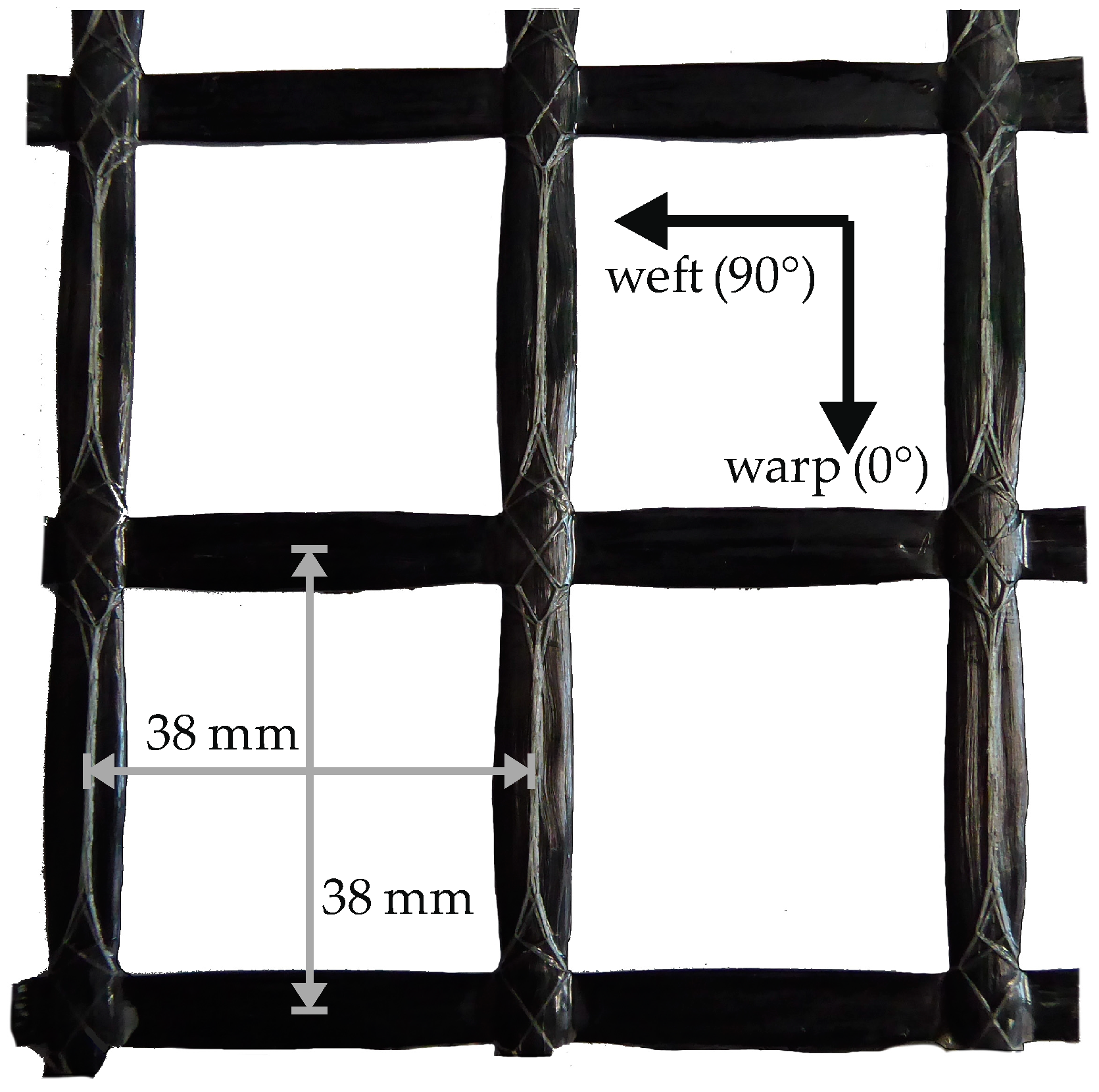
In this study, an epoxy resin impregnated carbon textile and a high-strength concrete were selected. The chosen biaxial texile solidian GRID Q95/95-CCE-38 from solidian GmbH, whose characteristics where determined in uniaxial single yarn tests [40] (Table 1). A section of the carbon textile reinforcement is displayed in Figure 1.
The requirements on the concrete had changed due to textile reinforcement, so that the concrete composition had to be adapted. The maximum grain size for the ability of penetration through the textile reinforcement [43], the long-term availability of the raw materials, ecological and economic criteria as well as a short-term feasibility of the results in construction practice were taken into account [44] for the development of the concrete, which was part of the basis project B2 of the C3 program.
The concrete composition used differs slightly from the compositions presented by Schneider et al. [44] because locally available raw materials were used. The maximum grain size is 4 mm, which means that the concrete can be classified as mortar. However, due to the high-strength properties, the term concrete was established. The composition of the high-strength concrete is shown in Table 2.
When concreting, first, the binder and the aggregate are mixed dry for one minute before water and the superplasticizer are added. After a further three minutes of mixing time, the concrete is poured in the formworks. Due to the self-compacting properties of the concrete, no vibration is required. After concreting, the test specimens in the formworks are protected against drying out. After one day, the formworks are removed, and the specimens are stored in water until the 7th day. From the 8th day, the samples are stored at room climate (approximately 20 °C and 65% RH). After reaching a minimum concrete age of 28 days, the test specimens are tested for their short-term, long-term and preloading behavior.
The compressive strength and flexural strength of the concrete were determined on test specimens according to DIN EN 196-1 [45] after 28 to 31 days. As an average of 36 specimens, the compressive strength was 123.7 MPa with a coefficient of variation (COV) of 7.7%. The average flexural strength was 12.2 MPa for 18 samples (COV 15.1%). The average modulus of elasticity was determined to be 43,839 MPa (COV 4.9%) [46] on six cylinders of 30 cm height and 15 cm diameter.
All test specimens are reinforced with a single layer of the carbon textile. The specimens have dimensions of w/t/l = 120/30/1000 mm3. Each specimen is reinforced with a section of the biaxial fabric with three yarns in test direction (warp direction, Figure 1). The concrete cover is 15 mm.
5. Experimental Investigations
5.1. Introduction
To determine a time to failure curve and a possible reduction factor for a certain service life, e.g., 100 years, for the material combination described in Section 4, long-term tests are carried out. By means of twenty short-term tests with a concrete age of 28 days, the reference load levels for the long-term tests are defined.
The test specimens of the long-term tests were initially preloaded with a final crack pattern for 24 h in tempered water on half of the reference load to ensure a uniform internal load distribution before the constant load is applied. In further tests the influence of the preloading is investigated.
Due to the environmental factors explained in Section 2, the preloading and long-term durability tests are performed under the combined impact of stress, temperature, moisture and alkalinity. The aim of the testing concept developed [19], and originally planned for these tests, was to carry out long-term tests over 200, 1000 and 5000 h. To derive a reduction factor at the end of the service life, a semi-logarithmic relationship between stress and time from variation of the constant stress levels is assumed. To determine a reduction factor, an extrapolation of the time to failure curve is necessary. However, the concept, which is successfully applicable to glass reinforcement, cannot be applied to the long-term tests with the carbon reinforcement presented in this paper, as no failure due to the exposure occurred during the test periods. In residual capacity tests, no reduction could be determined after the end of exposure. Therefore, a different approach will be necessary.
5.2. Experimental Procedure
5.2.1. Short-Term Tests
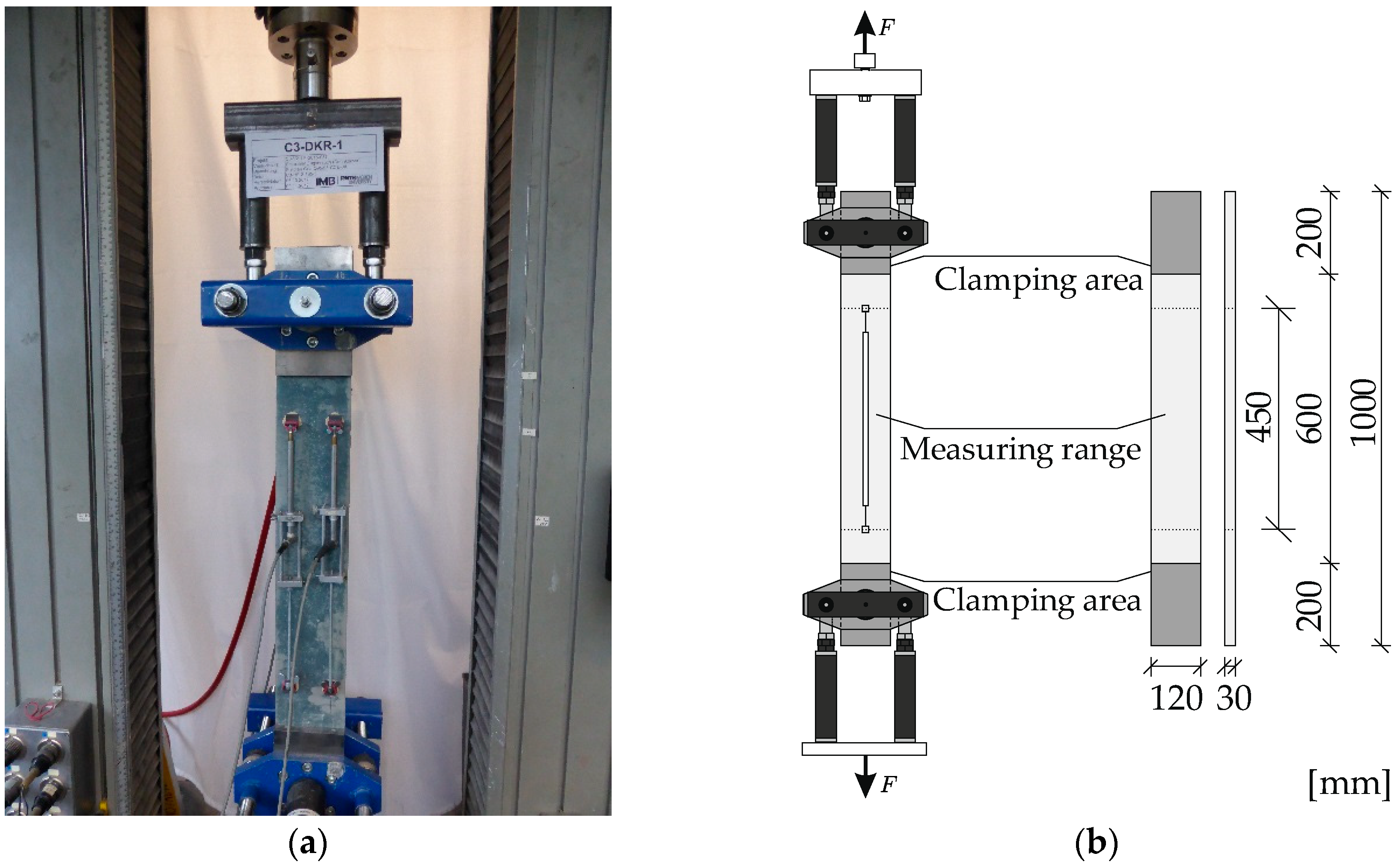
The tests were carried out in a universal testing machine with a maximum load of 100 kN. Two inductive displacement transducers were pasted on the formwork side and one on the filling side of each specimen to measure the deformations and determine the failure strain of the textile reinforcement.
The load is applied via hydraulic clamping devices through steel plates with clamping length of 200 mm (Figure 2).
The reference load for the long-term durability tests was determined at room temperature based on two test series, each consisting of ten test specimens. The specimens were tested at an age of 28 days and loaded monotonously with 1 mm/min until failure. The ultimate strain was evaluated at the time of the maximum stress.
5.2.2. Long-Term Tests
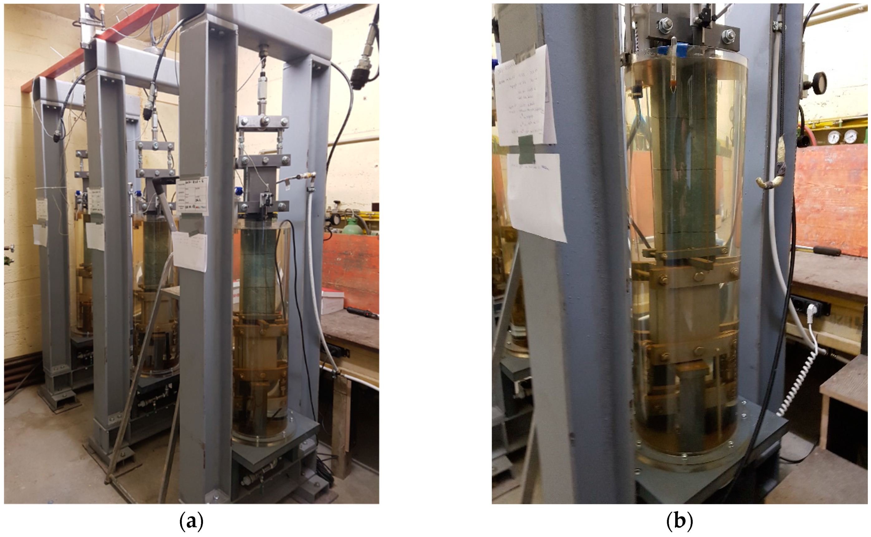
The long-term durability tests are carried out in especially developed test rigs (Figure 3a). Those rigs allow a long-term loading of the test specimens as well as a readjustment of the forces by hollow piston cylinders, which are operated hydraulically. In addition to the constant load, the specimens are exposed to tempered water (40 or 60 °C).
The tap water used is not exchanged during the entire test period. The pH-value of the water is 8 and rises rapidly to approximately 11 after dissolution of alkalis from the concrete of the test specimens. This results in an alkaline solution which, besides local attacks by the concrete pore solution on the reinforcement, leads to an attack on the reinforcement material. Accordingly, a simultaneous exposure of stress, moisture, temperature and alkalinity can be examined (Figure 3b).
The load is again applied via clamping devices made of steel plates (clamping length 250 mm). To ensure a permanent clamping of the test specimens, the clamping length increased by 50 mm compared to the short-term tests. The contact pressure is applied by lateral mechanically pretensioned threaded rods. Since the test specimens slipped out during first trial tests, the contact pressure increased to approximately 4.0 MPa (short-term tests 3.0 MPa). The reason for the slipping of the specimens is the thermal expansion of the threaded rods in the tempered water, which leads to a reduced contact pressure compared to the short-term tests.
To measure the creep deformations of the specimens or rather the carbon reinforcement, inductive displacement sensors are placed on the formwork and the filling side of the test specimens. Due to the length of the clamping devices, a test area of 500 mm and a measuring area of 450 mm were chosen.
While recording the deformations, the test specimens are loaded slowly in the tempered water, up to half of the reference load from the short-term tests. However, due to the high tensile strength of the concrete, no cracks will appear at this load level. Therefore, the specimens are loaded up to a final crack pattern before the load level is reduced back to half of the reference load and kept constant for 24 h.
This constant load serves as a preload for the test specimens, as it was specified in the project C3-V2.1. The influence of the preloading will be explained in detail in Section 6. After 24 h, the load level is applied and kept constant by manual readjustment over the entire test period until the failure of the specimens. The test time generally depends on the height of the load level.
5.2.3. Preloading Tests
The first part of the preloading tests is performed in the test rigs of the long-term tests (Figure 3a). The clamping devices and the measuring technology are therefore the same.
After 24 h of preloading, the three specimens are removed from the test rigs and dried for 24 h at room temperature. The residual load capacity of the test specimens is determined with the test setup described in Section 5.2.1.
The clamping length is again 250 mm, according to the long-term tests.
The procedure of the preloading is already described in Section 5.2.2. After 24 h of preloading in 60 °C tempered water, the test specimens are removed from the test rigs and dried for 24 h at room temperature. The test specimens are then installed in the testing machine described in Section 5.2.1 and loaded to the ultimate load at 1 mm/min.
6. Results
6.1. Short-Term Tests
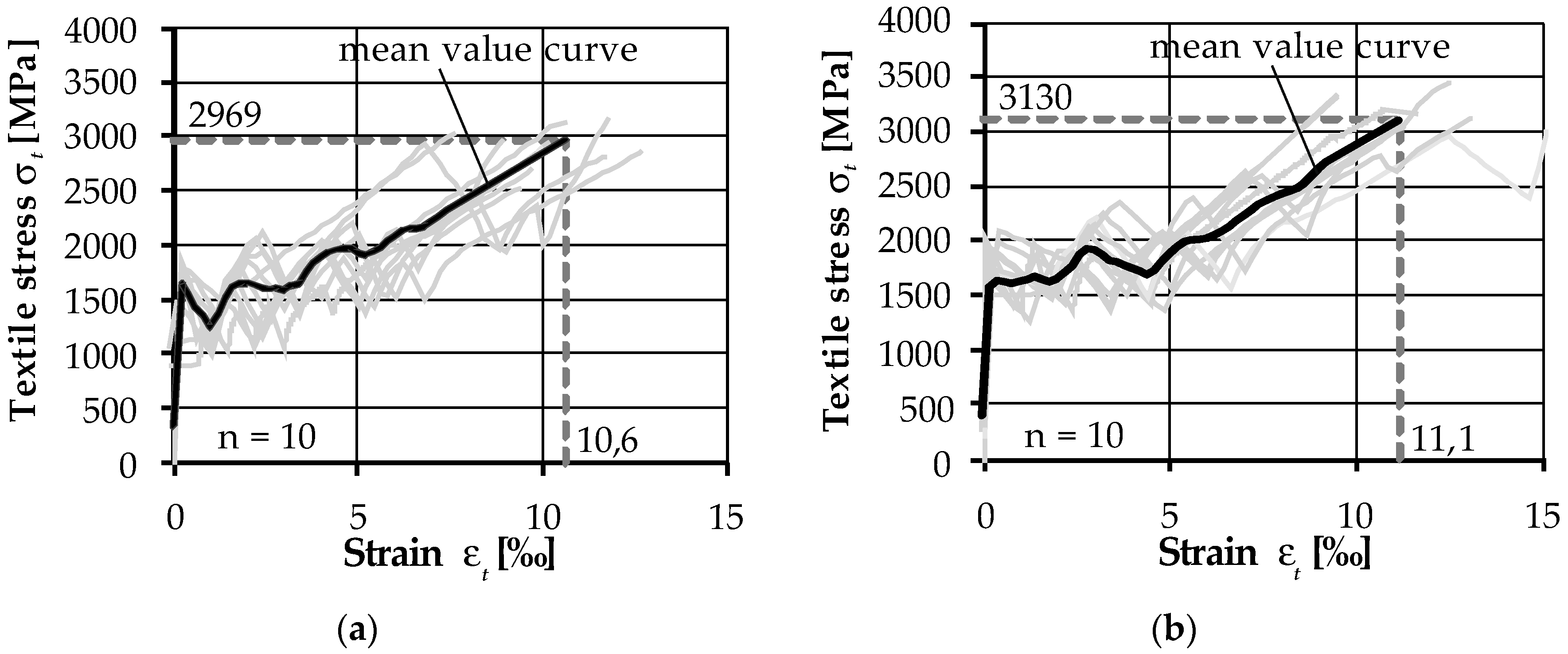
The results of the two-test series are presented in Figure 4. The mean failure stress σt,max of the first test series (Figure 4a) was 2969 MPa with a maximum strain εt of 10.6‰. The mean failure stress σt,max of the second test series (Figure 4b) was 3130 MPa with a maximum strain εt of 11.1‰. This results in a reference failure stress of 3050 MPa with a maximum strain of 10.9‰. The coefficient of variation is 9% for the mean failure stress and 17‰ for the mean strain at failure. The high variance of the strain εt can be explained with the indirect measurement of the deformations on the concrete.
The black line represents the mean value curve from each of the 10 individual curves, which was averaged over strain sections of 0.2‰. The reference load is necessary for the specification of the preloading and long-term durability load levels.
All tests specimens failed due to the rupture of the reinforcement. The minimum failure stress achieved in the first test series was 2532 MPa, while 2692 MPa was achieved in the second test series. The maximum failure stress was 3465 MPa and 3478 MPa, respectively. Two to four cracks occurred in the measuring range during the tests.
6.2. Long-Term Durability Tests
After the reference failure stress (3050 MPa) was determined, constant load levels were selected for the long-term durability tests. For the first load level the aim was to achieve failure within a few hundred hours based on the testing concept [19]. Subsequently, the load levels were to be reduced to reach test times of 1000 and 5000 h.
Table 3 provides an overview of the performed long-term durability tests (CLTT—Carbon Long-Term Tests). Specimens that failed during loading were excluded.
As displayed in Table 3, the specimens did not fail, with one exception, at loads exceeding 90% of the reference load, so that a few tests were stopped after 5000 to 6000 h to determine the residual capacity of the specimens. The failure of the specimen CLTT-6 is attributed to the non-applied preloading.
No decrease in strength could be observed in the residual load capacity—the ultimate capacity was even higher than the short-term strength. It is assumed that the preloading and the constant loading lead to an uniformization of the individual yarns and of the filaments in each yarn regarding stress and strain levels. This would increase the load capacity of the reinforcement. The effect of a preloading is presented in the next section and discussed in Section 7.
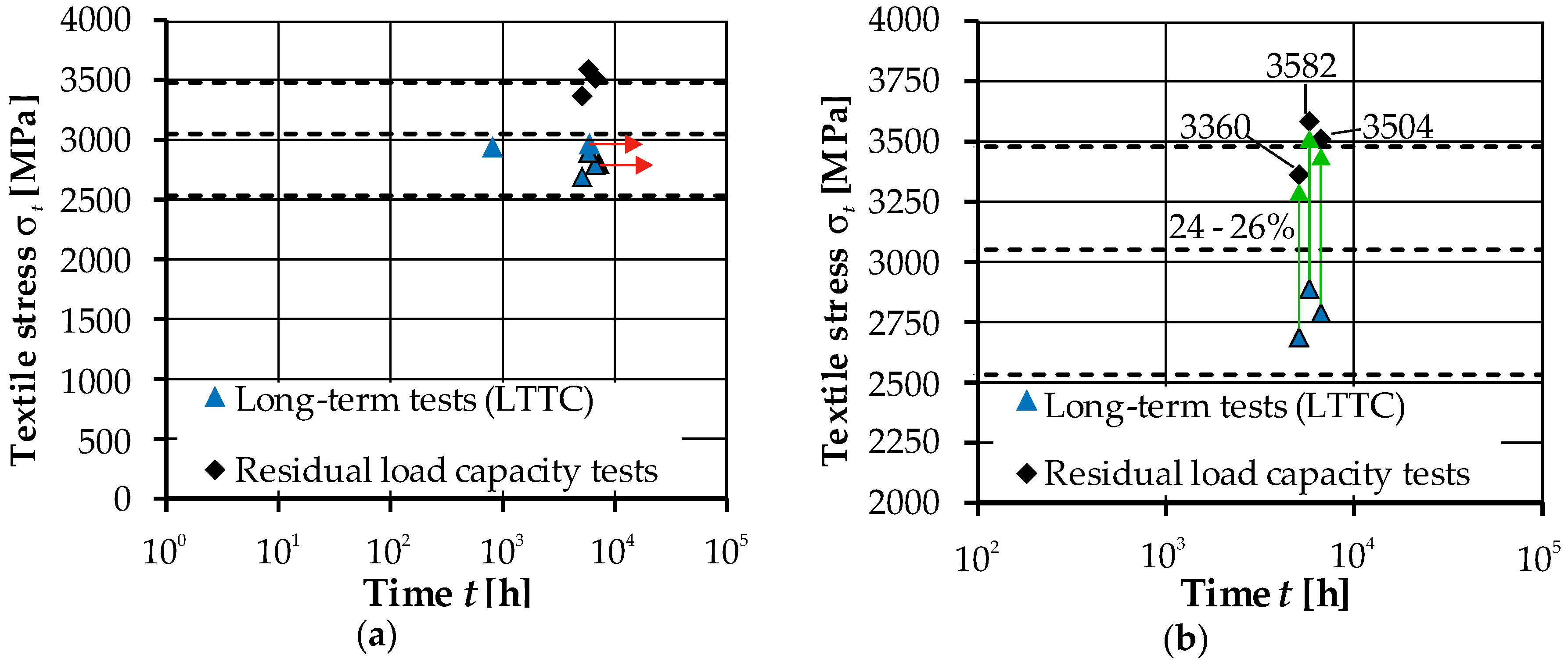
In Figure 5a the results of the long-term durability tests from Table 3 are plotted in a semi-logarithmic diagram. The red arrows in Figure 5a symbolize the ongoing tests. CLTT-1, which was started as a pretest and whose load level is clearly below that of the other tests, is not plotted in the diagram. Figure 5b displays the tests which were stopped after 5000 to 6000 h, as well as their respective residual capacities.
The dotted lines represent the maximum textile stress (3476 MPa), the reference stress (3050 MPa) and the lowest textile stress (2532 MPa) achieved in the short-term tests (Section 6.1). The upper and lower lines represent the scatter range of the ultimate stresses of the textile.
As described before, the original aim was the derivation of a time to failure curve for the tested material combination. Based on the test results, however, it is not possible to identify such a curve to determine the strength losses at the end of the service life. For this purpose, a starting point of the time to failure curve must be determined first. Since no failure of the long-term durability tests could be achieved within a few hundred hours due to the constant load levels and environmental factors, preloading tests are carried out.
Figure 5b clearly shows that the stopped tests still had a residual capacity of 24 to 26% above the constant load or 10 to 17% above the reference load, respectively. Therefore, no loss of strength could be detected. However, it is presumed that an alignment of the filaments occurs, which leads to an increase of the load capacity compared to the reference load. The results of the preloading tests are presented in the next section.
6.3. Preloading Tests
The preloading over 24 h in 60 °C tempered water led to an increase of 7% (3270 to 3050 MPa) in the load capacity compared to the reference load. The test specimes had two to three cracks in the measuring area as a result of the preloading. The number of cracks corresponds well with the number of cracks in the short-term (Section 6.1) and long-term durability tests (Section 6.2). When determining the residual capacity, no further cracks occurred so that each test specimen had already achieved a final saturated crack pattern.
A direct comparison of the stress strain curves is not feasible due to the removal of the specimens from the test rigs (Section 5.2.2) and the installation in the testing maschine for the short-term tests (Section 5.2.1).
The higher mean ultimate stress is attributed to the alignment of the filaments (training effect).
7. Discussion
No reduction of the long-term durability for the carbon textile reinforcement could be determined due to the environmental factors of stress, temperature, moisture and alkalinity. The comparison of the residual capacity tests to the short-term tests showed that no loss of strength occurs during the test times. Instead, an increase in the load capacity after more than 5000 to 6000 h was observed. This increase is attributed to a load-oriented alignment of the individual filaments (training effect). The non-exact alignment of the filaments in the production process is reduced because of the pre- and constant long-term load. This leads to an improvement of the ultimate tensile capacity in comparison with the short-term tests, which did not experience any preloading or constant load, respectively. At present, no level of degradation of the textiles exposed to long-term exposure compared to the short-term tests can be determined.
Three preloading tests verified the so-called ‘training effect’ and will be further investigated in future studies. An increase of 7% in the load capacity compared to the short-term tests was observed. The use of internal fiber sensors [47] could provide information on the exact strain of textile reinforcement in the crack area. This would enable the measurement of the actual strain of the reinforcement in the area of the concrete cracks and hence the development of the strain due to a pre- and constant long-term load. Furthermore, to verify the statement of the ‘training effect’, the test specimens of the accelerated long-term tests could be compared to test specimens loaded under real conditions.
According to the current state of investigations, it cannot be assumed that the results can directly be transferred to other material combinations of high-strength concrete and carbon textile reinforcement, because many characteristics of the technical textiles influence the long-term durability behavior. Furthermore, it cannot be excluded that the substances of the cementitious matrix will influence the long-term durability of the carbon textiles. At this point, however, it is assumed that investigations with exposure to a high alkaline concrete (pH value 13 to 14) are representative for other cementitious matrices.
Moreover, the investigated load levels will not occur in components. The actual textile stress in a component is significantly lower than the textile stresses at mean value level considered here, as the design of components is based, among other things, on design values. Therefore, the assumed maximum stress is not fully applied to components.
However, the results of the long-term tests of this work correspond well with results from literature. An overview of long-term tests on AFRP, CFRP and GFRP is presented in [27]. For example, Arockiasamy and Amer [48] did not notice any loss of strength at load levels of 65% of the breaking stress during tests on CFRP cables in alkaline solution with a pH value of 13 to 14 over nine months. Micelli and Nanni [21] investigated the durability of three different carbon rods under the influence of alkaline immersion and aging cycles. The test specimens stored for 21 or 42 days in an alkaline solution at 60 °C showed a loss of strength of 1% and 8%, respectively. After alternating combined environmental cycles, strength losses of less than 5% were found.
In accordance with the test results of this work, no or only a slight loss of strength is found in literature for CFRP tests. The durability behavior of CFRP reinforcement and carbon textiles differs due to the geometric properties (cross-sectional area, shape, impregnation material, etc.). However, since no results of long-term durability tests on carbon textiles are available, a reference is made. Due to different production processes of CFRP and carbon textile reinforcement, an increase in strength for the carbon textile reinforcement can be observed.
The test method that was to be used for the experiments could not be applied in this form, so there is a need for further development. Thereby, it must be taken into account that reliable characteristic values of the examination parameter can be derived [49].
8. Conclusions and Outlook
The long-term durability is the combined investigation of creep and alkaline resistance. A test method, which was developed by Weber and Baquero [17] and combines both exposures, was applied to small-scale specimens with a high-strength concrete and a single layer of an epoxy impregnated carbon reinforcement. To determine the long-term durability of the carbon reinforcement, short- and long-term, as well as preloading, tests were performed. Based on the short-term tests, the load levels for the long-term and preload tests were determined.
The results of this work can be summarized as follows:
- The long-term durability behavior of textile reinforcements is generally influenced by environmental factors, such as stress, temperature, moisture and alkalinity (pH-value). For this purpose, test rigs were developed which allow a combined exposure.
- Long-term durability tests with up to 11,000 h test time at temperatures of 40 and 60 °C were carried out at load levels of 70 to 97% of the reference load determined in short-term tests. With one exception, there was no failure due to the applied constant load levels.
- An increase of the ultimate load compared to the short-term tests could be identified in residual capacity tests. A load-oriented alignment of the filaments (training effect) is assumed, which leads to the higher load capacities of 10 to 17% compared to the short-term tests.
- Preloading tests at 60 °C confirmed this observation. After 24 h of preloading at 50% of the ultimate reference load, the residual capacity was 7% higher than the reference load.
Based on the long-term durability tests presented in this paper, it is not yet possible to derive a time to failure curve or a loss of strength for the material combination presented in Section 4. This corresponds to the test results of carbon reinforcement described in literature, where no or only minor strength losses were found. Within the framework of the C3-V2.1 project, further investigations will be carried out to validate the long-term durability of this and other material combinations with non-metallic carbon reinforcement. The aim is to determine the loss of strength over 100 years for this reinforcement to be able to safely and economically design carbon concrete components. As an outlook, it currently appears possible that no reduction due to external influences is necessary for this type of reinforcement. Moreover, the influence of a preload shall be further investigated.
Author Contributions
Conceptualization, A.S. and S.B.; formal analysis, A.S. and J.B.; experimental investigation, A.S.; data curation, A.S.; writing—original draft preparation, A.S.; writing—review and editing, A.S., S.B. and J.B.; visualization, A.S. and S.B.; supervision, J.H.; project administration, J.H.; funding acquisition, A.S. and J.H.
Funding
This research was funded by BMBF, grant number 03ZZ0321C.
Acknowledgments
The authors thank solidian GmbH for providing the carbon textile reinforcement.
Conflicts of Interest
The authors declare no conflict of interest. The founding sponsors had no role in the design of the study; in the collection, analyses, or interpretation of data; in the writing of the manuscript, and in the decision to publish the results.
References
- Sharei, E.; Scholzen, A.; Hegger, J.; Chudoba, R. Structural behavior of a lightweight, textile-reinforced concrete barrel vault shell. Compos. Struct. 2017, 171, 505–514. [Google Scholar] [CrossRef]
- Shams, A.; Hegger, J.; Horstmann, M. An analytical model for sandwich panels made of textile-reinforced concrete. Constr. Build. Mater. 2014, 64, 451–459. [Google Scholar] [CrossRef]
- Rempel, S.; Kulas, C.; Will, N.; Bielak, J. Extremely Light and Slender Precast Pedestrian-Bridge Made Out of Textile-Reinforced Concrete (TRC). In High Tech Concrete: Where Technology and Engineering Meet, Proceedings of the 2017 fib Symposium, Maastricht, The Netherlands, 12–14 June 2017; Hordijk, D.A., Luković, M., Eds.; Springer International Publishing: Cham, Switzerland, 2017; pp. 2530–2537. ISBN 3319594710. [Google Scholar]
- Schumann, A.; Michler, H.; Schladitz, F.; Curbach, M. Parking slabs made of carbon reinforced concrete. Struct. Concr. 2018, 19, 647–655. [Google Scholar] [CrossRef]
- Rempel, S.; Kulas, C.; Hegger, J. Bearing behavior of impregnated textile reinfrocement. In FERRO-11 International Symposium on Ferrocement and 3rd ICTRC International Conference on Textile Reinforced Concrete: Aachen, Germany, 7–10 June 2015; Brameshuber, W., Ed.; RILEM publications: Paris, France, 2015; pp. 71–78. [Google Scholar]
- May, S.; Steinbock, O.; Michler, H.; Curbach, M. Precast Slab Structures Made of Carbon Reinforced Concrete. Structures 2018, 18, 20–27. [Google Scholar] [CrossRef]
- May, S.; Michler, H.; Schladitz, F.; Curbach, M. Lightweight ceiling system made of carbon reinforced concrete. Struct. Concr. 2018, 19, 1862–1872. [Google Scholar] [CrossRef]
- Herbrand, M.; Adam, V.; Classen, M.; Kueres, D.; Hegger, J. Strengthening of Existing Bridge Structures for Shear and Bending with Carbon Textile-Reinforced Mortar. Materials 2017, 10, 1099. [Google Scholar] [CrossRef] [PubMed]
- Brameshuber, W.; Hinzen, M.; Dubey, A.; Peled, A.; Mobasher, B.; Bentur, A.; Aldea, C.; Silva, F.; Hegger, J.; Gries, T.; et al. Recommendation of RILEM TC 232-TDT: Test methods and design of textile reinforced concrete—Uniaxial tensile test: Test method to determine the load bearing behavior of tensile specimens made of textile reinforced concrete. Mater. Struct. 2016, 49, 4923–4927. [Google Scholar] [CrossRef]
- Schütze, E.; Bielak, J.; Scheerer, S.; Hegger, J.; Curbach, M. Einaxialer Zugversuch für Carbonbeton mit textiler Bewehrung. Beton- Und Stahlbetonbau 2018, 113, 33–47. [Google Scholar] [CrossRef] [Green Version]
- Lieboldt, M.; Tietze, M.; Schladitz, F. C3-Projekt—Erfolgreiche Partnerschaft für Innovation im Bauwesen. Bauingenieur 2018, 93, 265–273. [Google Scholar]
- Canadian Standards Association. CSA S807-10 (R2015): Specification for Fibre-Reinforced Polymers; Canadian Standards Association: Mississauga, ON, Canada, 2010. [Google Scholar]
- Canadian Standards Association. S806-12 (R2017): Design and Construction of Building Structures with Fibre-Reinforced Polymers; Canadian Standards Association: Mississauga, ON, Canada, 2012. [Google Scholar]
- American Concrete Institute. ACI 440.3R-12_ACI_2012_Guide Test Methods for Fiber-Reinforced Polymer (FRP) Composites for Reinforcing or Strengthening Concrete and Masonry Structures; American Concrete Institute: Farmington Hills, MI, USA, 2012. [Google Scholar]
- International Standard. ISO 10406-1: Fibre-Reinforced Polymer (FRP) Reinforcement of Concrete—Test Methods; ISO: Geneva, Switzerland, 2015. [Google Scholar]
- ASTM International. D7337/D7337M-12: Test Method for Tensile Creep Rupture of Fiber Reinforced Polymer Matrix Composite Bars; ASTM International: West Conshohocken, PA, USA, 2012. [Google Scholar]
- Weber, A.; Witt Baquero, C. New durability concept for FRP reinforcing bars: Combined durability and creep rupture testing allows for realistic design values. Concr. Int. 2010, 32, 49–53. [Google Scholar]
- Bank, L.C.; Gentry, T.R.; Thompson, B.P.; Russell, J.S. A model specification for FRP composites for civil engineering structures. Constr. Build. Mater. 2003, 17, 405–437. [Google Scholar] [CrossRef]
- Spelter, A.; Rempel, S.; Will, N.; Hegger, J. Testing Concept for the Investigation of the Long-Term Durability of Textile Reinforced Concrete. In Durability and Sustainability of Concrete Structures (DSCS-2018); Falikman, V., Realfonzo, R., Coppola, L., Hàjek, P., Riva, P., Eds.; American Concrete Institute: Farmington Hills, MI, USA, 2018; pp. 55.1–55.9. ISBN 978-1-64195-022-0. [Google Scholar]
- Ali, A.H.; Mohamed, H.M.; Benmokrane, B.; ElSafty, A. Effect of applied sustained load and severe environments on durability performance of carbon-fiber composite cables. J. Compos. Mater. 2018, 53, 677–692. [Google Scholar] [CrossRef]
- Micelli, F.; Nanni, A. Durability of FRP rods for concrete structures. Constr. Build. Mater. 2004, 18, 491–503. [Google Scholar] [CrossRef]
- Chen, Y.; Davalos, J.F.; Ray, I. Durability Prediction for GFRP Reinforcing Bars Using Short-Term Data of Accelerated Aging Tests. J. Compos. Constr. 2006, 10, 279–286. [Google Scholar] [CrossRef]
- Sen, R.; Mullins, G.; Salem, T. Durability of E-Glass/Vinylester Reinforcement in Alkaline Solution. ACI Struct. J. 2002, 99, 369–375. [Google Scholar]
- Benmokrane, B.; Wang, P.; Ton-That, T.M.; Rahman, H.; Robert, J.-F. Durability of Glass Fiber-Reinforced Polymer Reinforcing Bars in Concrete Environment. J. Compos. Constr. 2002, 6, 143–153. [Google Scholar] [CrossRef]
- Nkurunziza, G.; Benmokrane, B.; Debaiky, A.S.; Masmoudi, R. Effect of Sustained Load and Environment on Long-Term Tensile Properties of Glass Fiber-Reinforced Polymer Reinforcing Bars. ACI Struct. J. 2005, 615–621. [Google Scholar]
- Spelter, A.; Bielak, J.; Will, N.; Hegger, J. Long-term Durability of Textile Reinforced Concrete. In Proceedings of the 2018 fib Congress, Melbourne, Australia, 7–11 October 2018; Foster, S., Gilbert, I.R., Mendis, P., Al-Mahaidi, R., Millar, D., Eds.; Fédération Internationale du Béton fib/International Federation for Structural Concrete: Lausanne, Switzerland, 2018; pp. 1944–1954. [Google Scholar]
- International Federation for Structural Concrete. FRP Reinforcement in RC Structures; fib: Lausanne, Switzerland, 2007; ISBN 978-2-88394-080-2. [Google Scholar]
- Litherland, K.L.; Oakley, D.R.; Proctor, B.A. The use of accelerated ageing procedures to predict the long term strength of GRC composites. Cem. Concr. Res. 1981, 11, 455–466. [Google Scholar] [CrossRef]
- Wang, J.; GangaRao, H.; Liang, R.; Zhou, D.; Liu, W.; Fang, Y. Durability of glass fiber-reinforced polymer composites under the combined effects of moisture and sustained loads. J. Reinf. Plast. Compos. 2015, 34, 1739–1754. [Google Scholar] [CrossRef]
- Orlowsky, J.; Raupach, M. Durability model for AR-glass fibres in textile reinforced concrete. Mater. Struct. 2008, 41, 1225–1233. [Google Scholar] [CrossRef]
- Bank, L.C.; Russel Gentry, T.; Barkatt, A. Accelerated Test Methods to determine the Long-Term Behavior of FRP Composite Structures: Environmental Effects. J. Reinf. Plast. Compos. 1995, 14, 559–587. [Google Scholar] [CrossRef]
- Ehrenstein, G.W. Faserverbund-Kunststoffe. Werkstoffe-Verarbeitung-Eigenschaften; 2. Auflage; Hanser Verlag München Wien: München, Germany, 2006; ISBN 3-446-22716-4. [Google Scholar]
- Ray, B.C. Temperature effect during humid ageing on interfaces of glass and carbon fibers reinforced epoxy composites. J. Colloid Interface Sci. 2006, 298, 111–117. [Google Scholar] [CrossRef] [PubMed]
- Ceroni, F.; Cosenza, E.; Gaetano, M.; Pecce, M. Durability issues of FRP rebars in reinforced concrete members. Cem. Concr. Compos. 2006, 28, 857–868. [Google Scholar] [CrossRef]
- French, M.A.; Pritchard, G. Environmental stress corrision of hybrid fibre composites. Compos. Sci. Technol. 1992, 45, 257–263. [Google Scholar] [CrossRef]
- Mufti, A.A.; Banthia, N.; Benmokrane, B.; Boulfiza, M.; Newhook, J.P. Durability of GFRP composite rods. Concr. Int. 2007, 29, 37–42. [Google Scholar]
- Drzal, L.T.; Madhukar, M. Fibre-matrix adhesion and its relationship to composite mechanical properties. J. Mater. Sci. 1993, 28, 569–610. [Google Scholar] [CrossRef]
- Wang, Z.; Huang, X.; Xian, G.; Li, H. Effects of surface treatment of carbon fiber: Tensile property, surface characteristics, and bonding to epoxy. Polym. Compos. 2016, 37, 2921–2932. [Google Scholar] [CrossRef]
- Schutte, C.L. Environmental durability of glass-fiber composites. Mater. Sci. Eng. 1994, 255–324. [Google Scholar] [CrossRef]
- Rempel, S.; Ricker, M. Ermittlung der Materialkennwerte der Bewehrung für die Bemessung von textilbewehrten Bauteilen. Bauingenieur 2017, 92, 280–288. [Google Scholar]
- Rempel, S. Zur Zuverlässigkeit der Bemessung von biegebeanspruchten Betonbauteilen mit textiler Bewehrung. Ph.D. Dissertation, RWTH Aachen, Aachen, Germany, 2018. [Google Scholar]
- Hinzen, M. Prüfmethode zur Ermittlung des Zugtragverhaltens von textiler Bewehrung für Beton. Bauingenieur 2017, 92, 289–291. [Google Scholar]
- Hegger, J.; Voss, S. Investigations on the bearing behaviour and application potential of textile reinforced concrete. Eng. Struct. 2008, 30, 2050–2056. [Google Scholar] [CrossRef]
- Schneider, K.; Butler, M.; Mechtcherine, V. Carbon Concrete Composites C 3—Nachhaltige Bindemittel und Betone für die Zukunft. Beton- Und Stahlbetonbau 2017, 112, 784–794. [Google Scholar] [CrossRef]
- DIN Deutsches Institut für Normung e.V. Prüfverfahren für Zement—Teil 1: Bestimmung der Festigkeit; Beuth Verlag GmbH: Berlin, Germany, 2005. [Google Scholar]
- DIN Deutsches Institut für Normung e.V. DIN EN 12390-6:2010-09: Prüfung von Festbeton—Spaltzugfestigkeit von Probekörpern. Deutsche Fassung EN 12390-6:2009; Beuth Verlag GmbH: Berlin, Germnay, 2010. [Google Scholar]
- Schmidt-Thrö, G.; Scheufler, W.; Fischer, O. Kontinuierliche faseroptische Dehnungsmessung im Stahlbetonbau. Beton- Und Stahlbetonbau 2016, 111, 496–504. [Google Scholar] [CrossRef]
- Arockiasamy, M.; Amer, A. Studies on Carbon FRP (CFRP) Prestressed Concrete Bridge Columns and Piles in Marine Environment; Florida Department of Transportation: Tallahassee, FL, USA, 1998. [Google Scholar]
- Weber, A. Prüfkonzepte für Bewehrungsmaterialien mit zeitabhängigen Widerständen. Bauingenieur 2018, 93, 323–330. [Google Scholar]
Figure 1.
Detail of the tested textile carbon reinforcement.

Figure 2.
(a) Specimen in testing machine; (b) schematic (according to [10]) of the test setup for short-term tests.
Figure 2.
(a) Specimen in testing machine; (b) schematic (according to [10]) of the test setup for short-term tests.

Figure 3.
(a) Long-term durability test rigs; (b) Test specimen under exposure.

Figure 4.
Results of the first (a) and second (b) short-term test series.

Figure 5.
(a) Overview of the long-term durability tests; (b) stopped long-term durability tests and their residual capacity.
Figure 5.
(a) Overview of the long-term durability tests; (b) stopped long-term durability tests and their residual capacity.


Table 1.
Material characteristics of the carbon textile solidian GRID Q95/95-CCE-38 (properties of one individual yarn [41], test setup according to [42]).
| Characteristic | Unit | Warp Direction (0°) | Weft Direction (90°) |
|---|---|---|---|
| Modulus of elasticity | MPa | 244,835 | 243,828 |
| Mean ultimate stress | MPa | 3221 (n = 204 tests) | 3334 (n = 218 tests) |
| 5% quantile ultimate stress | MPa | 2737 | 2762 |
| 95% quantile ultimate stress | MPa | 3705 | 3906 |
| Axial spacing of yarns | mm | 38 | 38 |
| Cross-sectional area per yarn 1 | mm2 | 3.62 | 3.62 |
1 Filament area without epoxy impregnation.
Table 2.
Mix design of cementitious matrix for concrete HF-2-165-4 (mix design adapted from [44]).
Table 2.
Mix design of cementitious matrix for concrete HF-2-165-4 (mix design adapted from [44]).
| Substance | Density [kg/m3] | Content [kg/m3] |
|---|---|---|
| Binder compound CEM II/C-M Deuna | 2962 | 707 |
| Quartz sand F38 S | 2650 | 294 |
| Quartz sand 0.1–0.5 mm | 2630 | 243.2 |
| Quartz sand 0.5–1.0 mm | 2630 | 201.4 |
| Quartz sand 1.0–2.0 mm | 2630 | 148.9 |
| Quartz sand 2.0–4.0 mm | 2630 | 593.5 |
| Superplasticizer (polycarboxylatether base) MC-VP-16-0205-02 | 1070 | 15 |
| Water | 1000 | 165 |
Table 3.
Overview of the long-term durability tests.
| Tests | Constant Load [MPa] | Test Time [h] | Temperature [°C] | Ratio σt,x/σt,0 [-] | Residual Capacity [MPa] |
|---|---|---|---|---|---|
| CLTT-1 1 | 2168 | 11,000 | 40 | 0.71 | - |
| CLTT-2 | 2685 | 5117 | 40 | 0.88 | 3360 |
| CLTT-3 1 | 2795 | 7175 | 40 | 0.90 | - |
| CLTT-4 | 2813 | 5400 | 40 | 0.92 | 3504 |
| CLTT-5 | 2865 | 5300 | 40 | 0.94 | 3582 3 |
| CLTT-6 2 | 2933 | 811 | 60 | 0.96 | - |
| CLTT-7 1 | 2958 | 5930 | 40 | 0.97 | - |
1 Running test; 2 not preloaded, 3 reduced test area.
© 2019 by the authors. Licensee MDPI, Basel, Switzerland. This article is an open access article distributed under the terms and conditions of the Creative Commons Attribution (CC BY) license (http://creativecommons.org/licenses/by/4.0/).
Share and Cite
MDPI and ACS Style
Spelter, A.; Bergmann, S.; Bielak, J.; Hegger, J. Long-Term Durability of Carbon-Reinforced Concrete: An Overview and Experimental Investigations. Appl. Sci. 2019, 9, 1651. https://0-doi-org.brum.beds.ac.uk/10.3390/app9081651
AMA Style
Spelter A, Bergmann S, Bielak J, Hegger J. Long-Term Durability of Carbon-Reinforced Concrete: An Overview and Experimental Investigations. Applied Sciences. 2019; 9(8):1651. https://0-doi-org.brum.beds.ac.uk/10.3390/app9081651
Chicago/Turabian StyleSpelter, Arne, Sarah Bergmann, Jan Bielak, and Josef Hegger. 2019. "Long-Term Durability of Carbon-Reinforced Concrete: An Overview and Experimental Investigations" Applied Sciences 9, no. 8: 1651. https://0-doi-org.brum.beds.ac.uk/10.3390/app9081651
Note that from the first issue of 2016, this journal uses article numbers instead of page numbers. See further details here.