Mechanical Behavior of a Double-Column Self-Centering Pier Fused with Shear Links

1
School of Civil Engineering, Key Laboratory of New Technology for Construction of Cities in Mountain Area, Chongqing University, Chongqing 400045, China
2
Key Laboratory of Civil Engineering Safety and Durability of China Education Ministry, Department of Civil Engineering, Tsinghua University, Beijing 100084, China
*
Author to whom correspondence should be addressed.
Appl. Sci. 2019, 9(12), 2497; https://0-doi-org.brum.beds.ac.uk/10.3390/app9122497
Submission received: 10 May 2019
/
Revised: 5 June 2019
/
Accepted: 17 June 2019
/
Published: 19 June 2019
(This article belongs to the Special Issue Extreme Sciences and Engineering)
Abstract
:Featured Application
A double-column self-centering pier fused with shear links is proposed as a novel structure, which can improve the seismic resilience of bridges. Corresponding simplified FE model and theoretical model are developed. The research outcome of this work can guide the design of the innovated pier.
Abstract
A double-column self-centering pier fused with shear links is a novel structure developed to reduce residual deformation and facilitate post-earthquake repair. With this novel structure, the seismic resilience of bridges can be improved, and the reliability of lifeline infrastructure can be ensured. This paper presents the proposed pier configuration and investigates the mechanical behavior of the pier. A simplified finite element model is established to develop the lateral force-displacement relationship under cyclic loading. Additionally, a theoretical model based on the matrix displacement method and the virtual work principle is proposed to calculate the lateral force-displacement skeleton curve. The rationality and reliability of the theoretical model are validated by the satisfactory agreement observed between the numerical and theoretical results. Furthermore, a series of parametric analyses are conducted to discuss the effects of key parameters. The outcomes of this work can serve as a reference for further development of the design method for the innovated pier.

1. Introduction
In recent years, enhancing the seismic resilience of structures, communities, and even nations has received extensive attention in the field of earthquake engineering [1,2]. In 2015, the importance of promoting the resilience of new and existing critical infrastructure (water, transportation, telecommunications infrastructure, etc.) was emphasized at the Third United Nations World Conference on Disaster Risk Reduction [3]. These critical infrastructures play a crucial role in post-earthquake relief and reconstruction. However, previous post-earthquake surveys have shown that conventional reinforced concrete piers dissipate seismic energy through plastic hinge zones, which results in residual drifts and irreparable damage. For instance, after the 1995 Japan Kobe earthquake, approximately 100 reinforced concrete piers, with residual drift ratios exceeding 1%, were demolished [4].
Based on the lessons learned from previous earthquakes, several pier systems have been proposed to satisfy the requirements of seismic resilient structures [5,6]. Pioneering research on rocking bridge columns incorporating unbonded posttensioning was conducted by Mander and Cheng [7]. Later, Hewes and Priestley experimentally investigated the response of segmental bridge piers with unbonded prestress tendons [8]. Subsequently, experimental and analytical studies were performed by many researchers to demonstrate the potential advantages of self-centering piers [9,10,11,12,13]. Corresponding results confirmed that unbonded posttensioning could effectively mitigate residual deformation. However, despite the desirable self-centering capacity, the energy dissipating capacity is less than satisfactory. Therefore, a hybrid system, a posttensioned structure assembled with additional energy dissipation, is proposed [14]. This system results in a flag-shaped hysteretic relationship. Many studies have been conducted for further validation of the superiority of the hybrid pier system and the development of various solutions for energy dissipation. In previous studies, the energy dissipating capability of the hybrid system was enhanced in two ways: (1) Embedding internal energy dissipation (ED) devices consisting of mild steel bars or shape-memory-alloy bars with unbonded length at the critical joint [15,16,17,18,19,20,21,22]. Obviously, such internal ED devices are not readily replaceable if damaged after a major earthquake, which increases the difficulty of post-earthquake restoration. (2) Installing external ED devices (viscous energy dissipation, steel dissipater, aluminum bars, etc.) around the bottom of the piers [20,23,24,25,26,27,28]. However, the limited installation space for external ED devices restricts the development of energy dissipation performance. Moreover, the external ED devices located at the bottom of the piers are more vulnerable to other natural and artificial factors, such as corrosion from water, impacts from vehicles, or floating debris.
Replaceable shear links have been successfully applied in buildings [29,30,31,32] and bridges [33,34,35,36,37,38] as sacrificial elements to dissipate seismic energy. Inspired by previous research, this work proposes a novel pier system, which combines the advantages of both self-centering piers and replaceable shear links. As shown in Figure 1, the pier system relies on unbonded prestress steel strands to provide self-centering forces and adopts shear links between the columns to act as reformative external ED devices. The shear link consists of two parts, i.e., the replaceable part and the pre-embedded part, which are connected by high strength grade 12.9 bolts. During a severe earthquake (E2 level earthquake defined in Chinese Code [39], the largest acceleration in the lateral acceleration response spectrum is 0.34 g), inelastic deformation is concentrated in the replaceable part of the shear link, while the damage of key components (bent cap, columns, footing, unbonded prestress steel strands, and the pre-embedded parts of the shear links) can be prevented. In addition, the bolted connection ensures that the damaged parts can be easily and quickly replaced, which will accelerate post-earthquake restoration. Furthermore, the interval between the columns provides adequate space for the shear links. Therefore, sufficient energy dissipation of the proposed pier system can be guaranteed.
Although the double-column self-centering pier with shear links has outstanding seismic performance theoretically, the nonlinear behavior and design method of the pier have not been systematically studied. An experimental study of the entire pier system is costly and difficult. Consequently, in this work, a finite element (FE) model of the proposed pier is developed, and the mechanical behavior of the proposed double-column self-centering pier fused with shear links is investigated. The investigation is mainly focused on the application of the innovated pier in urban viaducts, the piers of which are not slender. To calculate the lateral force-displacement skeleton curve, a theoretical model based on the matrix displacement method and the virtual work principle is established. The outcomes of this study can benefit the further development of the design method of the innovated pier.
2. FE Model and Validation
The FE method is adopted to study the performance of the pier. Although experimental work on the proposed double-column self-centering pier fused with shear links does not exist, relevant experiments on self-centering piers and shear links, which are the key components of the proposed pier, can be found in the literature. Consequently, the experimental results of the key components are adopted to validate the rationality of the proposed model.
2.1. Modeling Method
To improve simulation efficiency, a two-dimensional FE model was built to determine the mechanism of double-column self-centering piers with shear links, using the general-purpose FE program MSC.Marc (MSC Software Corporation, CA, USA, 2007) [40]. A sketch illustrating the main model components is shown in Figure 2. Four-node quadrilateral plane stress elements are employed to simulate the columns, bent cap, and footing; 2-node truss elements with initial stress are employed to simulate the unbonded prestress steel strands. According to previous relevant investigations [8,9,10,11,12,13,14], during the rocking process of the self-centering pier, the footing, bent cap, and prestress steel strands remain elastic, with limited damage in the contact area at both ends of the column. Therefore, the aforementioned parts are set as elastic. In addition, the shear links are modeled by elasto-plastic springs as presented in Section 2.2.2. Furthermore, the contact between the columns and the bent cap/footing is simulated by the contact function provided by MSC.Marc [40]. The elements in the potential contacting parts of the columns and bent cap/footing are defined as two separated sets of contact bodies. During the iteration process, each node in the contact bodies is repeatedly checked. The program calculates the contact tolerance according to the size of elements. If a node is within the contact tolerance, it will be considered to be in contact with other elements. In a tangential direction of the contact interface, an approximation of the Coulomb friction model (i.e., arctangent model) is adopted to represent the relationship between the normal stress and tangential stress at the contact interface.
2.2. Validation of Modeling Method
2.2.1. Self-Centering Pier
The experiment conducted by Guo et al. [17], as shown in Figure 3, is employed to validate the modeling of the self-centering component. The specimen has a height of 1700 mm with a 400 × 400 mm cross section. Grade C60 concrete (Chinese concrete grade, measured uniaxial unconfined compressive strength fc = 52.7 MPa, measured elastic modulus Ec = 3.8 × 10⁴ MPa) is adopted, while 20 mm diameter hot rolled ribbed steel bars (measured yield strength fy = 349 MPa, measured elastic modulus Es = 202 GPa) and 15.2 mm diameter strands (ultimate strength fPT = 1860 MPa, elastic modulus Es = 195 GPa) are used for the internal ED bars and unbonded prestress steel strands, respectively. The average prestress of each strand is 78.26 kN.
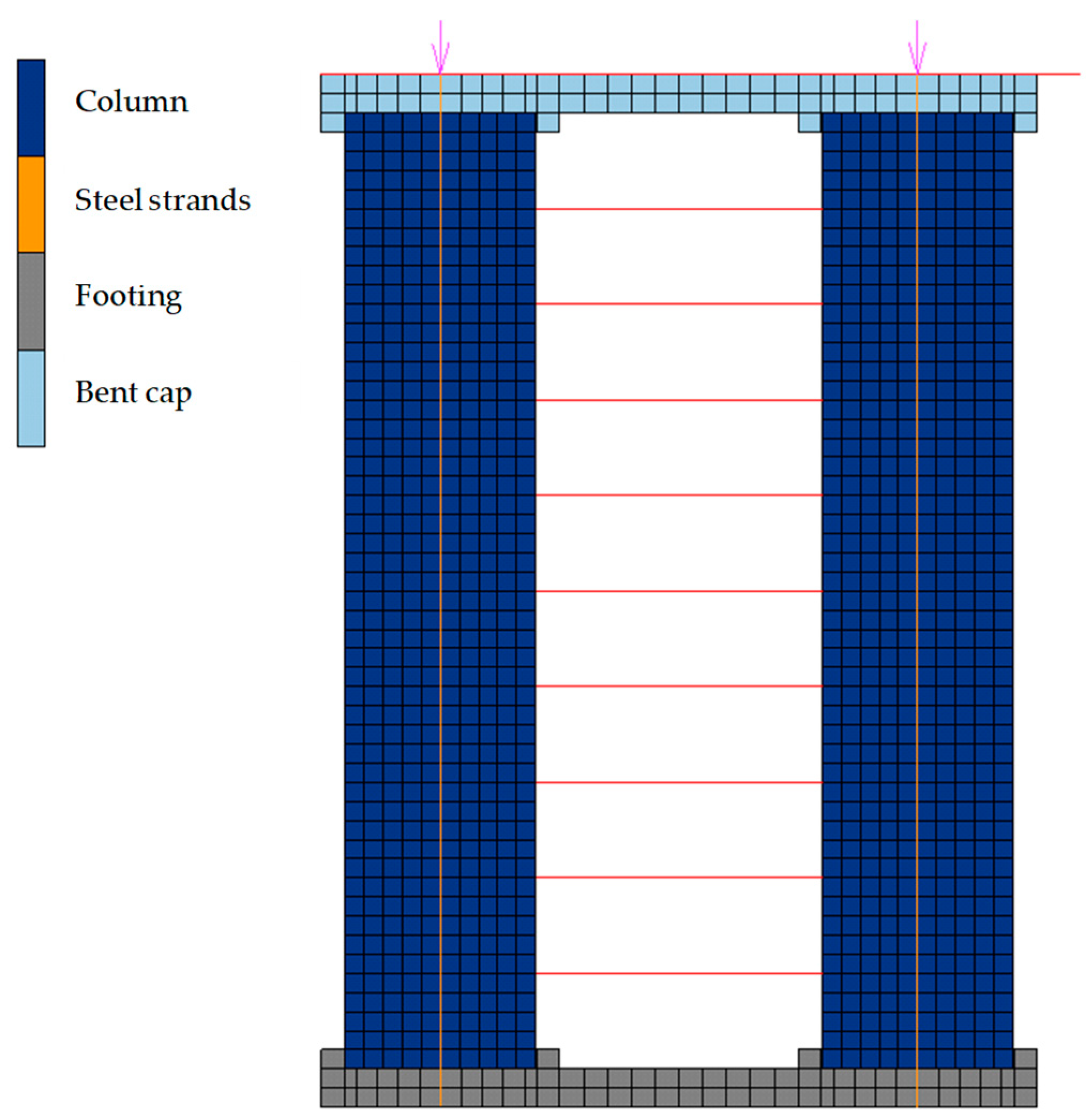
The FE model is illustrated in Figure 4. The aforementioned modeling method of the columns, the bent cap, the footing, and the unbonded prestress steel strands in Section 2.1 has been adopted. Note that the unbonded parts of the internal ED bars are modeled by elasto-plastic 2-node truss elements, while the bonded parts share nodes with the concrete elements. The initial stress of the unbonded prestress steel strands is set as 431.3 MPa according to the test results.
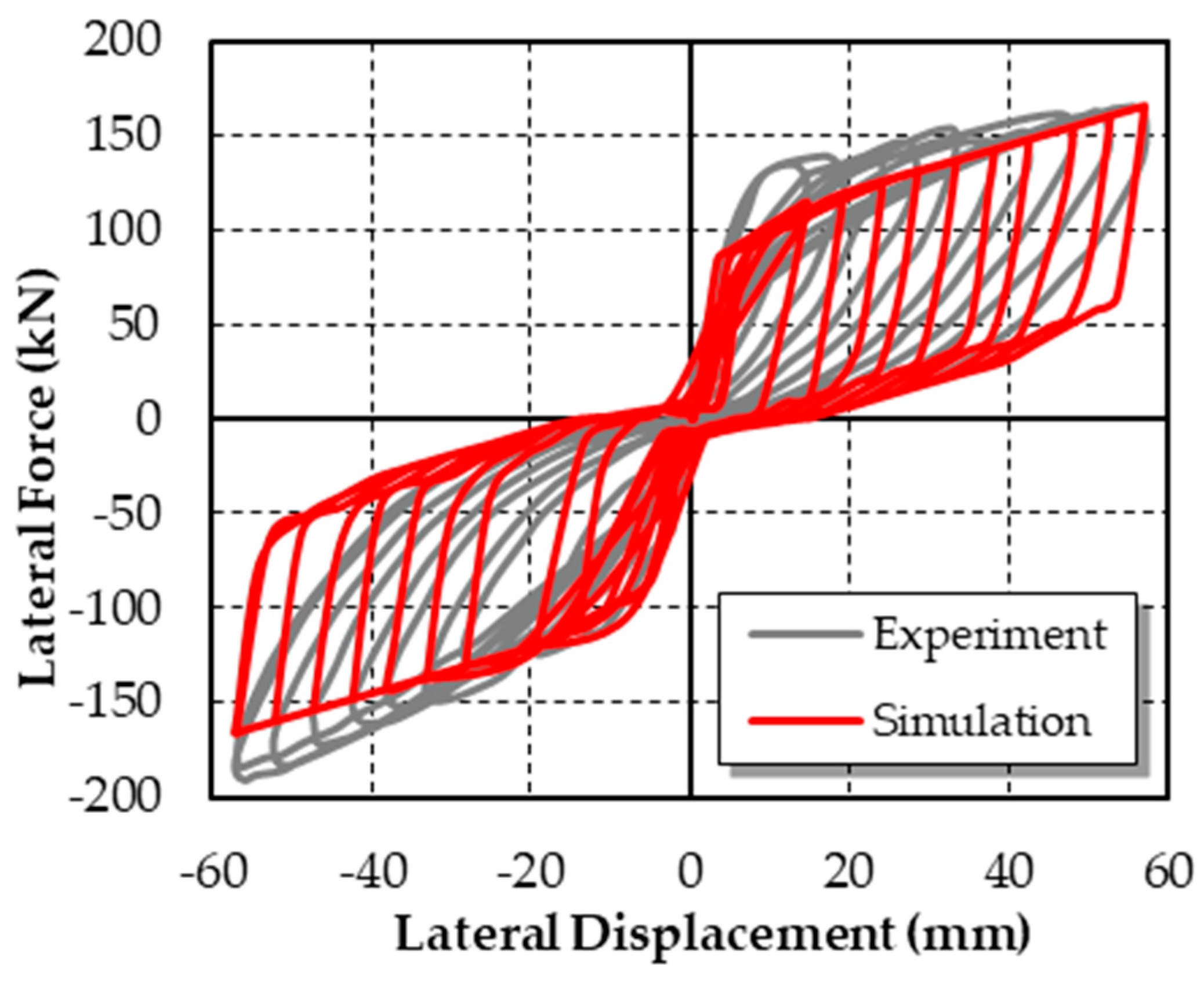
The hysteretic curves are shown in Figure 5. The comparison of experimental results and simulation results demonstrates the validity of the self-centering pier model.
2.2.2. Shear Links
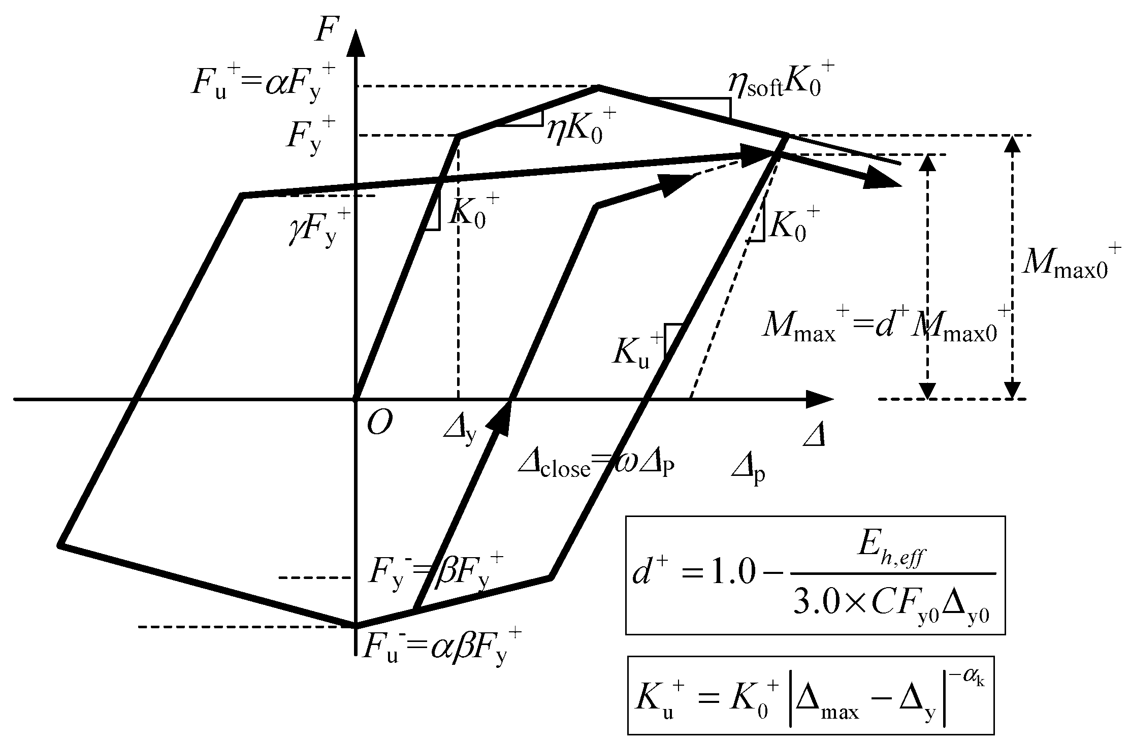
The hysteretic model proposed by Lu et al. [41], as shown in Figure 6, is adopted to simulate the nonlinear behavior of the shear links between the columns. The prominent features of Lu’s model [40] are as follows: (1) The yielding, hardening and softening behavior are considered, as well as the pinching and strength and stiffness deterioration effects under cyclic loading; (2) different positive and negative yield strengths can be represented. Previous research [41,42,43] indicates that the hysteretic model can efficiently simulate the nonlinear behavior of various components, especially a successful application in the simulation of shear links in tall buildings [42]. Consequently, the hysteretic model is adopted in this study to simulate the shear links between columns.
The model is mainly controlled by the following parameters: (1) C, a dimensionless accumulated hysteretic energy dissipation parameter that reflects the capacity of resisting strength degradation caused by the cyclic loading; (2) γ, a parameter representing the pinching effect; (3) ω, a parameter representing the position of the end point of slip; (4) αk, a parameter defining unloading stiffness; (5) K0, initial stiffness; (6) Fy, yield strength; (7) η, hardening ratio; (8) ηsoft, softening ratio; and (9) α, the ratio of peak strength to yield strength. These parameters can be divided into two categories: parameters (1)–(4), namely, the backbone curve parameters, describing the force-displacement backbone curve under the cyclic lateral load; and parameters (5)–(9), namely, the hysteretic parameters, specifying the hysteretic rules. The experiment conducted by Ji et al. [44] is employed to calibrate the hysteretic parameter values.
3. Performance of Double-Column Self-Centering Piers with Shear Links under Quasi-Static Cyclic Loading
An FE model of the double-column self-centering piers with shear links was built based on the modeling method presented in Section 2. Each column has a height of 3.00 m with a 2.00 m × 2.00 m cross section, and the clear distance between the columns is 3.00 m. The steel strand in each column has a total area of 15424 mm2 and an initial stress of 1395 MPa. Further, a vertical concentrated load of 3.08 × 10⁴ kN is applied at the bent cap to simulate the superstructure gravity. Grade C60 concrete (Chinese concrete grade, standard uniaxial unconfined compressive strength fc = 38.5 MPa, standard elastic modulus Ec = 3.6 × 10⁴ MPa) is adopted, while 15.2 mm diameter strands (ultimate strength fPT = 1860 MPa, elastic modulus Es = 195 GPa) are used for unbonded prestress steel strands. The initial stiffness and yield strength of the adopted shear link are 6.0×10⁵ kN/m and 1.4 × 10⁶ kN, respectively. The responses of the piers under quasi-static cyclic loading are discussed in this section.
3.1. Rocking Process
Figure 8 illustrates the rocking process of the pier. The column-footing interface remains closed until the lateral force has increased to the force at the imminent gap opening. Then, the columns begin to rotate about the compression toe. Large nonlinear rotations can be sustained at the column-footing and column-cap beam joints with minimal structural damage. However, high stress may develop in the contact area during joint gap opening; the maximum stress is 179 MPa, at the edge of the contact area. Therefore, the joints should be strengthened (e.g., by installing steel jacketing) to avoid local failure and corresponding posttensioning losses.
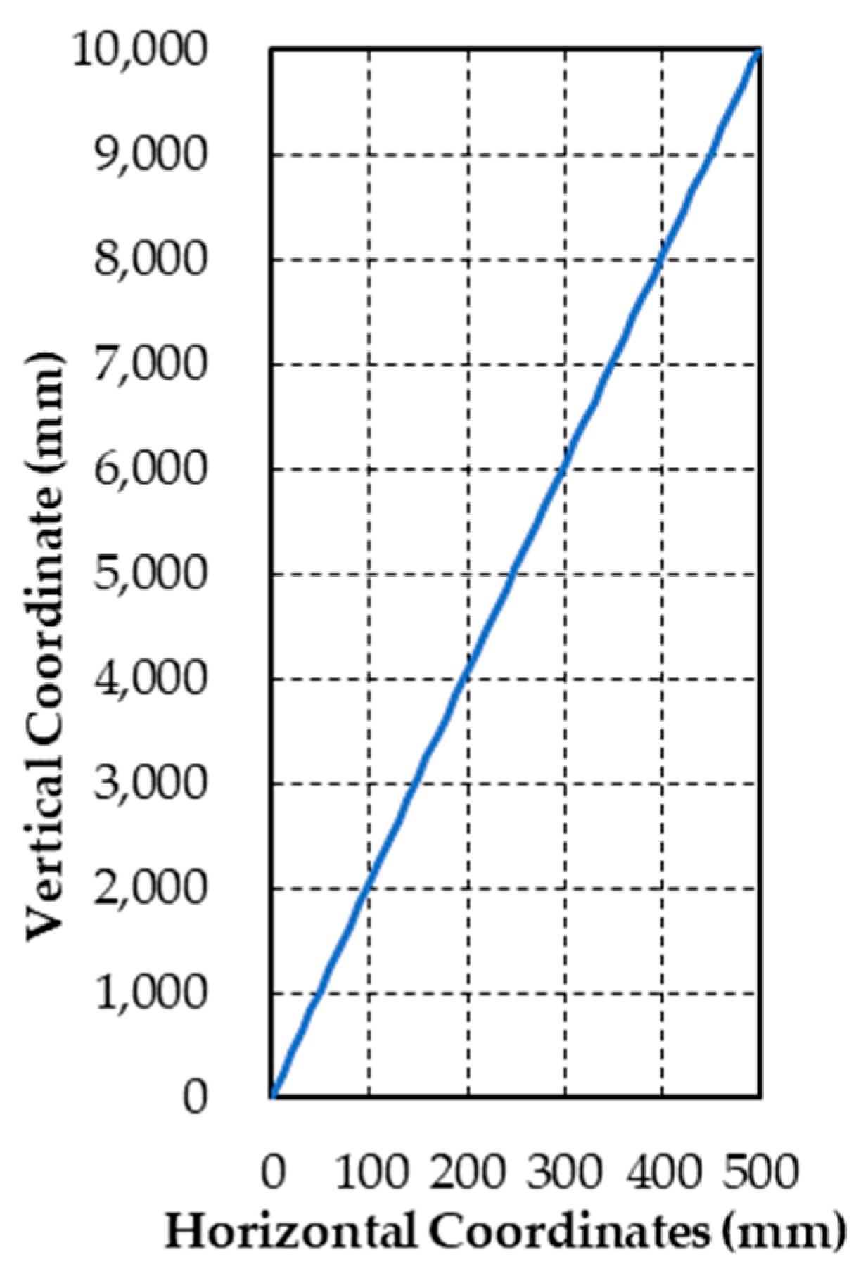
Figure 9 shows the coordinates of the column axis while the pier rocks at the maximum lateral displacement (the centroid of the bottom column section is the coordinate origin). As shown, the column axis is approximately a straight line. The rigid-body motion significantly affects the displacement. Consequently, the deformation of each column under the action of lateral loads can be neglected.
3.2. Influence of Shear Link Arrangement
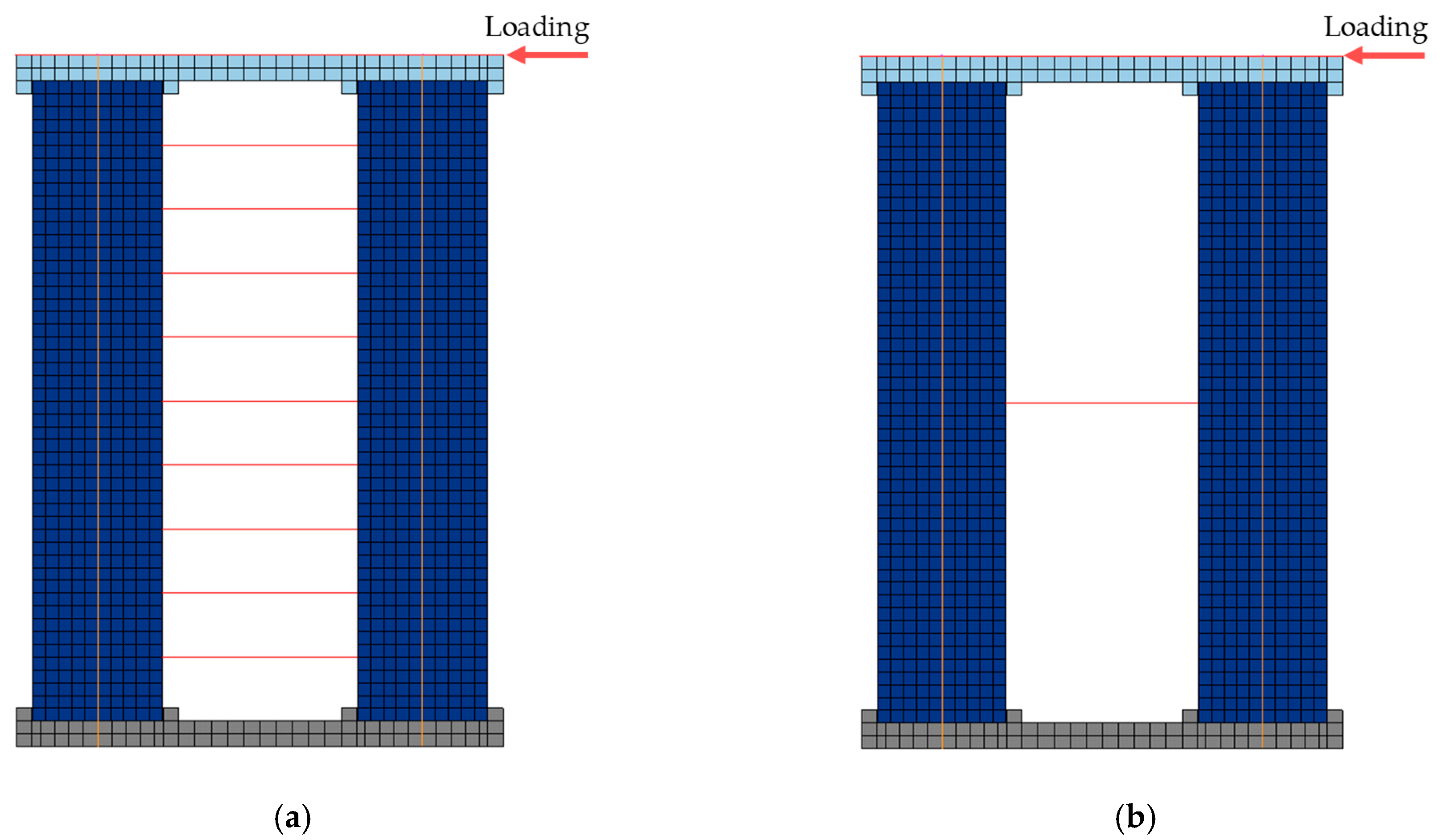
As shown in Figure 10, a uniformly distributed spring model (Figure 10a) and an integrated spring model (Figure 10b) were built to compare the influence of the shear link arrangement. Note that the spring in the integrated spring model is a superposition of the springs in the uniformly distributed spring model, i.e., and , where kISM and FyISM represent the initial stiffness and yield strength of the spring in the integrated spring model, respectively, while kUDSMi and FyUDSMi represent the initial stiffness and yield strength of each spring in the uniformly distributed spring model, respectively; n is the number of springs.
Comparing the results of the two models (Figure 11), it can be concluded that the shear link arrangement has little impact on the hysteretic performance of the hybrid bridge pier. The reason for this phenomenon is that the relative shear displacement of each shear link is subjected to the identical rigid-body motions of the columns. Therefore, the analysis and discussion of this study are based on the integrated spring model. Note that the integrated spring model is more convenient for computing, while uniformly distributed shear links will be adopted in reality to significantly reduce the difficulties in construction.
4. Theoretical Analysis of Double-Column Self-Centering Piers with Shear Links
The comparison in Section 2.2 validates the rationality of the FE model. To make computing and design more convenient, a theoretical model is preferred. Consequently, this section will develop a theoretical model for the proposed pier system.
4.1. Theoretical Model Parameters
The parameters in the theoretical model of the double-column self-centering piers with shear links can be divided into the following five groups:
- Geometrical dimensions: h and Apier are the height and cross section of the columns, respectively; d is the distance between columns and APT is the area of steel strands.
- Material properties: Ec and fc are the elastic modulus and axial compressive strength of concrete, respectively; EPT and fPT are the elastic modulus and the ultimate strength of steel strands, respectively.
- Gravitational forces: Wbeam and Wpier are superstructure gravity and column gravity, respectively.
- Shear link parameters: kSL and FySL are the initial stiffness and yield strength of shear links, respectively.
- Other: FPT0 is the initial prestress of the steel strands. All of these parameters are illustrated in Figure 12.
4.2. Piers with Shear Links
4.2.1. Pre-Rocking State
Before rocking, the pier can be simplified as the model in Figure 13a, in which the bent cap is considered an undeformable rigid body. During this period, the columns and shear link deform under the lateral force F. Due to the symmetry of the frame, the calculation model can be further simplified as shown in Figure 13b.
In the simplified model, the geometric parameters l and x are half of the pier height and half of the distance between the column axes, respectively:
The matrix displacement method is used. The corresponding global coordinate system is established and the information of the nodes and elements is shown in Figure 13b. There are six independent nodal displacements: the angular displacements of nodes B(u3) and E(u6); the horizontal linear displacements of nodes B(u1), C(u4), D(u4), and E(u5); and the vertical linear displacement of node B(u2). Obviously, u4 can be considered the lateral displacement at the top of the pier ux, i.e., ux = u4. Since elements ① and ② in Figure 13b refer to the column, A1, I1, and E1 are the area, inertia moment, and elastic modulus of each column, which are expressed as
where Ec is the elastic modulus of concrete.
It is reasonable to assume that the shear stiffness of the shear links is equal to the bending stiffness of element ④ in Figure 13b, and the shear links do not bear compressive axial force. Consequently, Equations (6) and (7) can be obtained as
The element stiffness matrix of elements ① and ② (Figure 13b) in the local coordinate system can be expressed as:
Transforming the element stiffness matrix of elements ① and ② in Figure 13b from the local coordinate system to the global coordinate system, it is determined that
For element ④ in Figure 13b, the local coordinate system is in accordance with the global coordinate system. Thus, its element stiffness matrix in the global coordinate system can be expressed as
By merging the entries of the element stiffness matrices into the structural stiffness matrix based on the sequence number of the displacements, and superimposing the entries with the same displacement sequence, the structural stiffness equation can be obtained as
where
is referred to as the structural stiffness matrix. In addition, the forces and displacements in the global coordinate system can be expressed as:
These equations can be solved to determine the relationship between the lateral load and lateral displacement at the top of the pier:
Substituting Equations (1)–(7) into Equation (15) yields:
4.2.2. Rocking State
According to the observation in Section 3.2, under the action of lateral loads, the deformation of each column can be neglected, with only the rigid-body displacements of the superstructure, bent cap, and columns remaining.
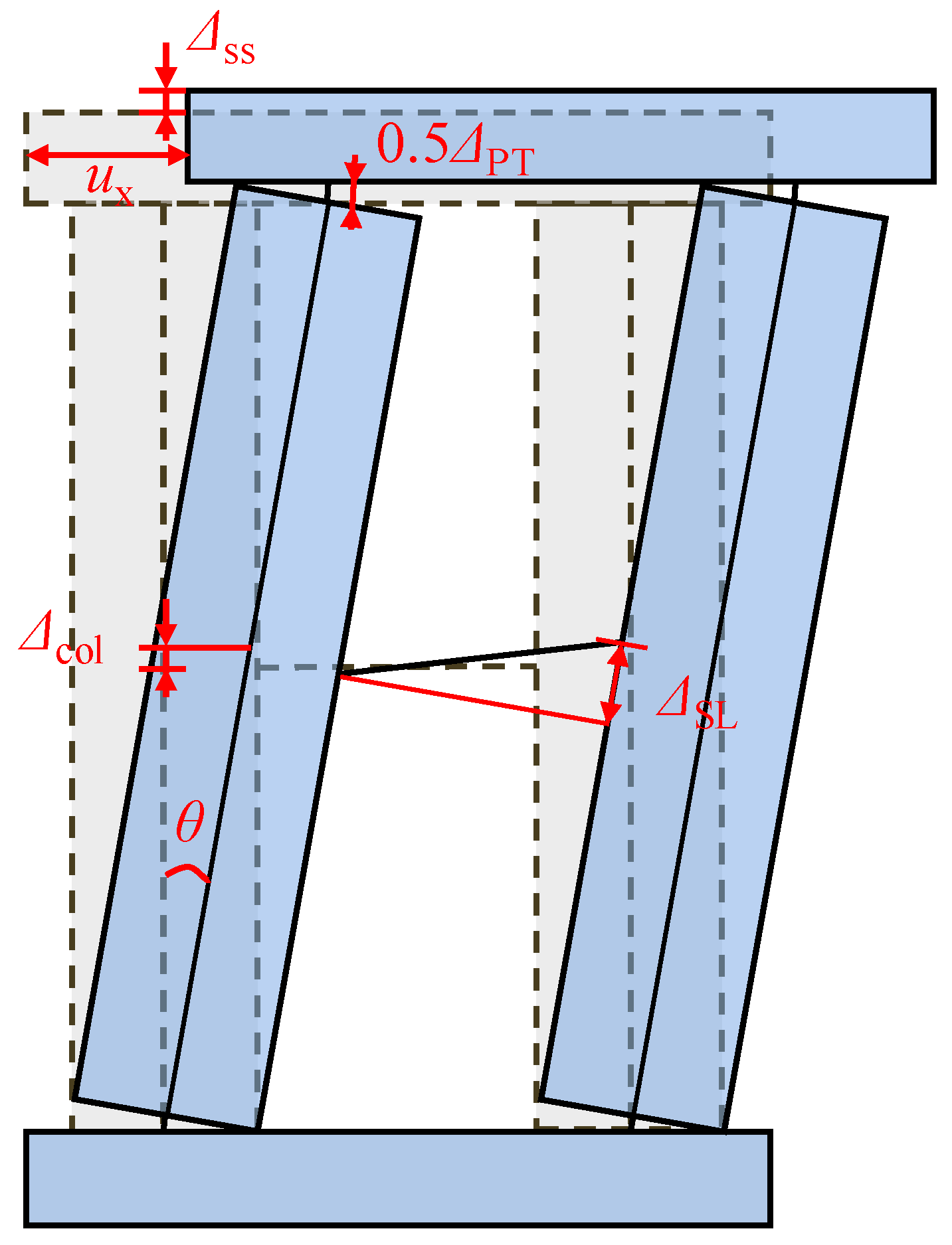
As shown in Figure 14, is the elongation of unbonded steel strands; and are the rising height of the superstructure and pier, respectively; is the relative shear displacement between the ends of the shear link; and ux is the lateral displacement at the top of the pier. The relationship between the above displacements and the rotation angle of the column can be directly obtained based on the principle of displacement compatibility:
Before the stress of the unbonded steel strands reaches the ultimate strength, the force provided by the unbonded steel strands, FPT (θ) is
Assuming that the constitutive model of the shear links is perfectly elasto-plastic with yield strength Fy, the shear force at the ends of the shear link, FSL(θ), is
where is the relative shear displacement between the ends of the shear link when the shear link yields.
According to the principle of the virtual work, the total work done by the applied forces and the inertial forces of a structure in equilibrium equals zero for any virtual displacement. Therefore, Equation (24) is obtained as
where , , , , and are the virtual displacements along the directions of applied lateral force, the prestress in the steel strands, the shear force at the ends of the shear link, the superstructure gravity, and the column gravity, respectively, which can be derived from Equations (17)–(21).
Substituting Equations (25)–(29) into Equation (24) yields:
4.3. Piers without Shear Links
If there are no shear links between the columns, Equations (16) and (30) are degenerated as:
where all parameters have been described previously.
4.4. Model Validation
In this section, the aforementioned equations to calculate the lateral force-displacement skeleton curve are validated by the FE simulations of the double-column self-centering piers with and without shear links. The FE models are built based on the modeling method presented in Section 2, and the corresponding parameters are listed in Table 1.
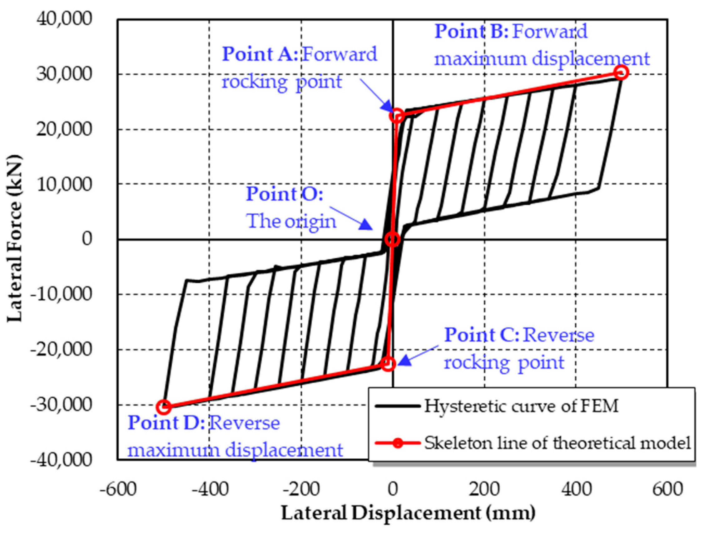
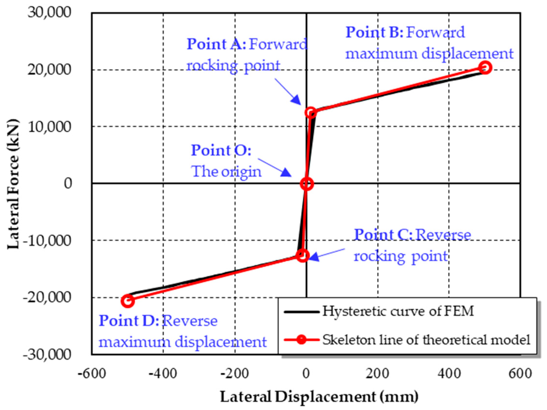
The theoretical and FE results of the double-column self-centering pier with shear links are shown in Figure 15, while the results of the double-column self-centering pier without shear links are shown in Figure 16. The skeleton curve calculated by using the theoretical model consists of four parts. Curves OA and AB refer to the pre-rocking state and rocking state in the positive lateral loading condition, respectively, while curves OC and CD refer to the pre-rocking state and rocking state in the negative lateral loading condition, respectively. The results derived from the theoretical models are in accordance with the results from the FE models. However, during the pre-rocking state, when the lateral displacement approaches the critical point between the pre-rocking and rocking states, the stiffness of the theoretical model is greater than the stiffness of the FE model. This occurs is because the columns are modeled as rigid bodies in the theoretical model. However, the deformation of the column ends will result in decreased stiffness. Further, comparing Figure 15 and Figure 16, it can be seen that the shear links between columns endow the pier with a preferable energy dissipation ability.
5. Parametric Analysis
Considering that the dimensions of the pier are usually controlled by the construction space and normal loads, such as gravity and vehicles, only parameters related to shear links and steel strands are discussed in this section. Further, the parametric analysis is conducted on the basis of parameters listed in Table 1. In other words, when a specified parameter is studied, the other parameters in Table 1 remain unchanged.
5.1. Influence of Initial Stiffness of Shear Links (kSL)
The hysteretic curves of the double-column self-centering pier with shear links, when the initial stiffness of the shear links increases from 8000 kN/m to 24,000 kN/m with an increment of 4000 kN/m, are shown in Figure 17. The initial stiffness of shear links only has a small influence on the initial stiffness and unloading stiffness of the pier, which is negligible.
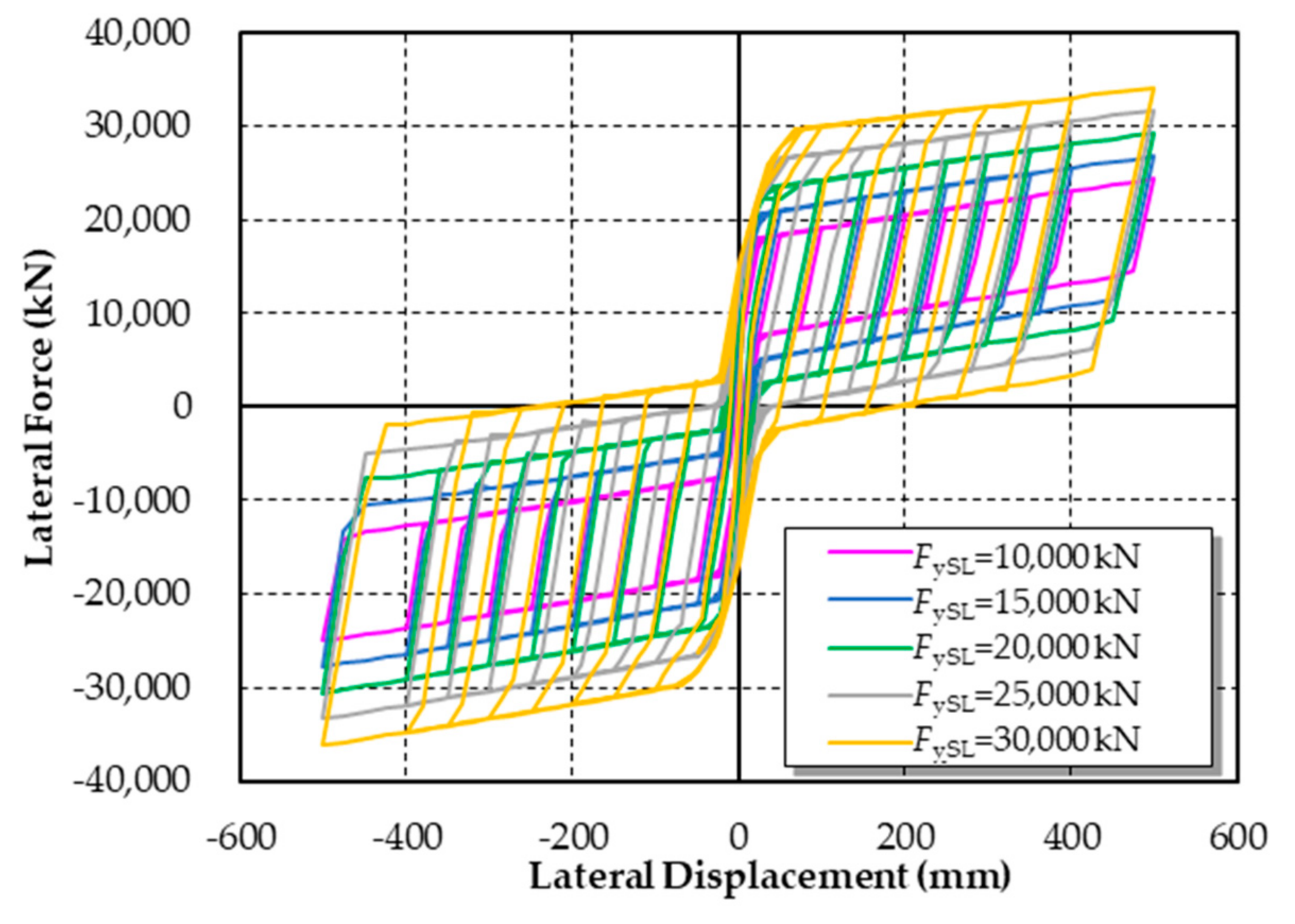
5.2. Influence of Yield Strength of Shear Links (FySL)
The hysteretic curves of the double-column self-centering pier with shear links, when the yield strength of the shear links increases from 10,000 kN to 30,000 kN with an increment of 5000 kN, are shown in Figure 18. The yield strength of the shear links has little influence on the stiffness of the pier but has a notable influence on the energy dispassion and the residual displacement. When the yield strength of shear links increases, the energy dissipation capacity of the pier improves significantly. Meanwhile, the residual displacement becomes larger.
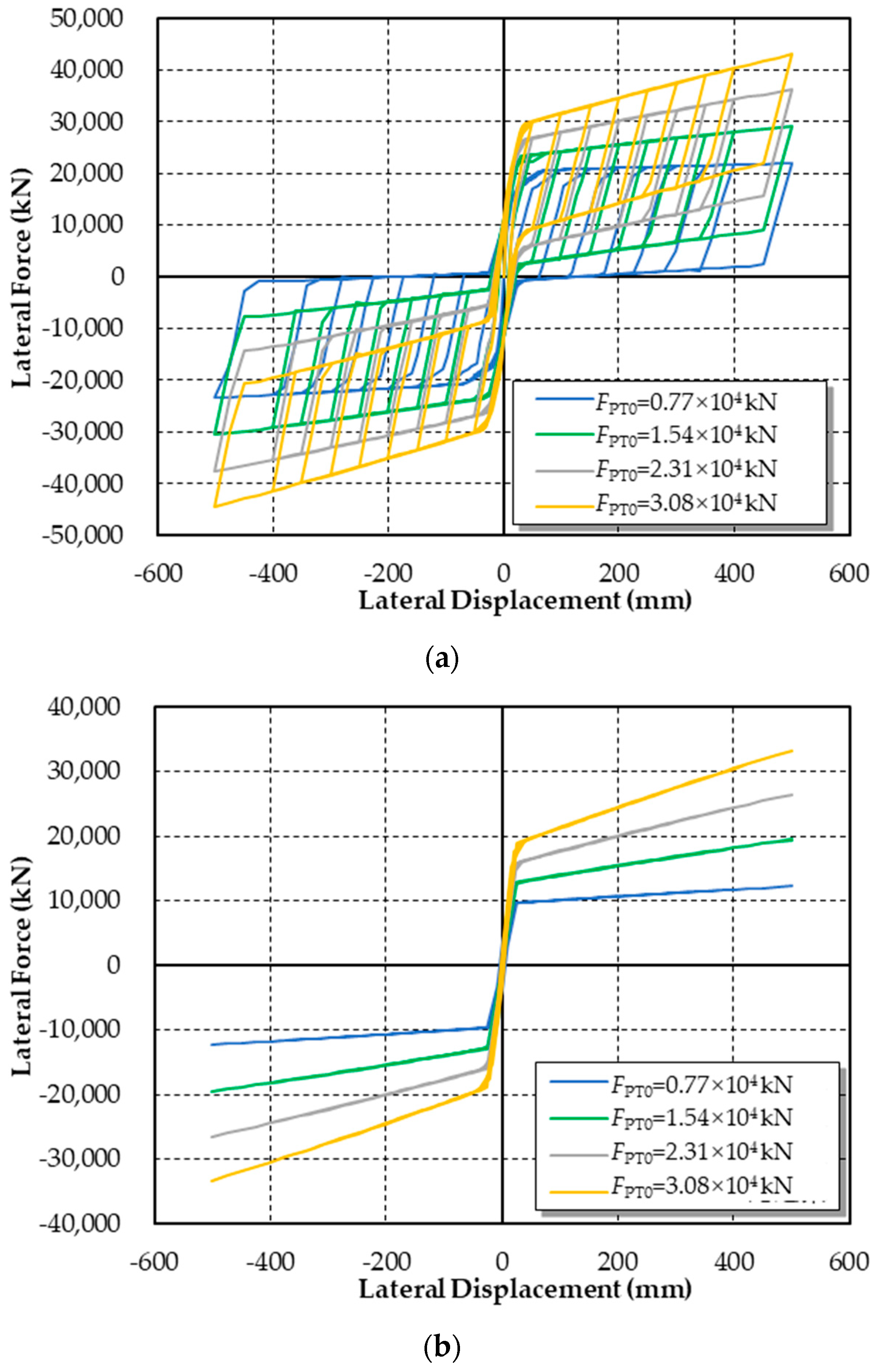
5.3. Influence of Initial Prestress of Steel Strands (FPT0)
When the initial prestress of steel strands increases from 0.77 × 10⁴ kN to 3.08 × 10⁴ kN with an increment of 0.77 × 10⁴ kN, the hysteretic curves of the double-column self-centering pier both with and without shear links are shown in Figure 19. For both piers, the initial prestress of steel strands mainly affects stiffness during the rocking process. The bigger the initial prestress is, the larger the rocking stiffness of the pier is. Further, the initial prestress of the steel strands can efficiently reduce the residual displacement.
6. Conclusions
A double-column self-centering pier with shear links was proposed to improve the seismic resilience of bridges. A corresponding FE model was established, and a theoretical model was developed to calculate the pier lateral force-displacement skeleton curve. Moreover, a series of parametric analyses were conducted to determine the effects of key parameters. The following conclusions can be drawn:
- The prestressed steel strands provide the proposed pier with a stable self-centering ability, which efficiently reduces the residual displacement. Additionally, the rocking behavior effectively prevents the development of plastic hinges in the columns of conventional reinforced concrete piers. Furthermore, the shear links between columns guarantee the pier has a preferable energy dissipation ability. Therefore, the proposed pier can be used to improve seismic resilience with the remarkable features mentioned above.
- The results of the FE model indicate that, for the short piers, it is reasonable to neglect the deformation of each column when the pier rocks. The integrated spring model and the uniformly distributed spring model show almost the same hysteretic performance. These two observations are the basis of the theoretical model.
- The results derived from the theoretical models show good agreement with the results from the FE models. In this case, the theoretical model based on the matrix displacement method and the virtual work principle can be used for future analysis of the innovated pier.
- According to the parametric analyses, the influence of the initial stiffness of the shear links can be neglected. By enhancing the yield strength of shear links, the energy dissipation capacity of the pier can be improved but the residual displacement will increase. Further, the bigger the initial prestress is, the larger the rocking stiffness of the pier is and the smaller the residual displacement is.
Author Contributions
X.L. conceived the concept and guided the research, L.X. conducted all the analytical work and wrote the manuscript, and Q.Z., L.Y., and J.D. reviewed the manuscript.
Funding
The authors are grateful for the financial support received from National Key R&D Program of China (2016YFC0701202), the National Natural Science Foundation of China (No. 51808074), and the Fundamental Research Funds for the Central Universities (No.106112017CDJXY200001).
Conflicts of Interest
The authors declare no conflict of interest.
References
- Hyogo Earthquake Engineering Research Center; NIED NEES Consortium, Inc. Report of the Seventh Joint Planning Meeting of NEES/E-Defense Collaborative Research on Earthquake Engineering; Report PEER 109; University of California: Berkeley, CA, USA, 2010. [Google Scholar]
- National Research Council. National Earthquake Resilience: Research, Implementation, and Outreach; National Academies Press: Washington, DC, USA, 2011. [Google Scholar]
- The United Nations Office for Disaster Risk Reduction (UNISDR). 2015. Available online: http://www.unisdr.org/files/43291_sendaiframeworkfordrren.pdf. (accessed on 16 April 2019).
- Kawashima, K.; MacRae, G.A.; Hoshikuma, J.; Nagaya, K. Residual displacement response spectrum. J. Struct. Eng. 1998, 124, 523–530. [Google Scholar] [CrossRef]
- Bruneau, M.; Chang, S.E.; Eguchi, R.T.; Lee, G.C.; O’Rourke, T.D.; Reinhorn, A.M.; Shinozuka, M.; Tierney, K.; Wallace, W.A.; von Winterfeldt, D. A framework to quantitatively assess and enhance the seismic resilience of communities. Earthq. Spectra 2006, 19, 733–738. [Google Scholar] [CrossRef]
- Tremayne, H.; Mahin, S.A. Earthquake Engineering for Resilient Communities: 2012 PEER Internship Program Research Report Collection; Technical Report PEER 07; University of California: Berkeley, CA, USA, 2012. [Google Scholar]
- Mander, J.B.; Cheng, C.T. Seismic Resistance of Bridge Piers Based on Damage Avoidance Design; Technical Report NCEER 97-0014; University of Buffalo: Buffalo, NY, USA, 1997. [Google Scholar]
- Hewes, J.T.; Priestley, M.J.N. Seismic Design and Performance of Precast Concrete Vertebral Bridge Columns; Report No. SSRPe2001/25; Department of Structural Engineering, University of California: San Diego, CA, USA, 2002. [Google Scholar]
- Kwan, W.P.; Billington, S. Unbonded posttensioned concrete bridge piers. i: Monotonic and cyclic analyses. J. Bridge Eng. 2003, 8, 92–101. [Google Scholar] [CrossRef]
- Kwan, W.P.; Billington, S. Unbonded posttensioned concrete bridge piers. ii: Seismic analyses. J. Bridge Eng. 2003, 8, 102–111. [Google Scholar] [CrossRef]
- Sakai, J.; Mahin, S.A. Analytical Investigations of New Methods for Reducing Residual Displacements of Reinforced Concrete Bridge Column; Report No. PEER 2004/02; Pacific Earthquake Engineering Research Center, University of California: Berkeley, CA, USA, 2004. [Google Scholar]
- Heiber, D.G.; Wacker, J.M.; Eberhard, M.O.; Stanton, J.F. Precast Concrete Pier Systems for Rapid Construction of Bridges in Seismic Regions; Report No. WA-RD 611.1; Washington Department of Transportation: Olympia, WA, USA, 2005. [Google Scholar]
- Ou, Y.C.; Chiewanichakorn, M.; Ahn, I.S.; Aref, A.J.; Chen, S.S.; Filiatrault, A.; Lee, G.C. Cyclic performance of precast concrete segmental bridge columns: Simplified analytical and finite element studies. Transp. Res. Rec. 2006, 1976, 66–74. [Google Scholar] [CrossRef]
- Palermo, A.; Pampanin, S.; Calvi, G.M. Concept and development of hybrid solutions for seismic resistant bridge systems. J. Earthq. Eng. 2005, 9, 899–921. [Google Scholar] [CrossRef]
- Ou, Y.; Chiewanichakorn, M.; Aref, A.; Lee, G. Seismic performance of segmental precast unbonded posttensioned concrete bridge columns. J. Struct. Eng. 2007, 133, 1636–1647. [Google Scholar] [CrossRef]
- Roh, H.; Reinhorn, A.M. Hysteretic behavior of precast segmental bridge piers with superelastic shape memory alloy bars. Eng. Struct. 2010, 32, 3394–3403. [Google Scholar] [CrossRef]
- Guo, J.; Xin, K.G.; Wu, W.P.; He, M.H. A simplified model and experimental response of self-centring bridge piers with ductile connections. In Proceedings of the 2nd International Conference on Structures and Building Materials, Hangzhou, China, 12–15 August 2012. [Google Scholar]
- Roh, H.; Ou, Y.C.; Kim, J.; Kim, W.S. Effect of yielding level and post-yielding stiffness ratio of ED bars on seismic performance of PT rocking bridge piers. Eng. Struct. 2014, 81, 454–463. [Google Scholar] [CrossRef]
- Nikbakht, E.; Rashid, K.; Hejazi, F.; Osman, S.A. Application of shape memory alloy bars in selfcentring precast segmental columns as seismic resistance. Struct. Infrastruct. Eng. 2015, 11, 297–309. [Google Scholar] [CrossRef]
- Guerrin, G.; Restrepo, J.I.; Massari, M.; Vervelidis, A. Seismic behavior of posttensioned self-centering precast concrete dual-shell steel columns. J. Struct. Eng. 2015, 141, 04014115. [Google Scholar] [CrossRef]
- Li, C.; Hao, H.; Bi, K.M. Numerical study on the seismic performance of precast segmental concrete columns under cyclic loading. Eng. Struct. 2017, 148, 373–386. [Google Scholar] [CrossRef]
- Wang, J.C.; Ou, Y.C.; Chang, K.C.; Lee, G.C. Large-scale seismic tests of tall concrete bridge columns with precast segmental construction. Earthq. Eng. Struct. Dyn. 2008, 37, 1449–1465. [Google Scholar] [CrossRef]
- Marriott, D.; Pampanin, S.; Palermo, A. Quasi-static and pseudo-dynamic testing of unbonded post-tensioned rocking bridge piers with external replaceable dissipaters. Earthq. Eng. Struct. Dyn. 2009, 38, 331–354. [Google Scholar] [CrossRef]
- Guo, T.; Cao, Z.L.; Xu, Z.K.; Lu, S. Cyclic load tests on self-centering concrete pier with external dissipators and enhanced durability. J. Struct. Eng. 2016, 142, 04015088. [Google Scholar] [CrossRef]
- Cao, Z.L.; Wang, H.; Guo, T. Fragility analysis of self-centering prestressed concrete bridge pier with external aluminum dissipators. Adv. Struct. Eng. 2017, 20, 1210–1222. [Google Scholar] [CrossRef]
- Nikoukalam, M.T.; Sideris, P. Resilient bridge rocking columns with polyurethane damage-resistant end segments and replaceable energy-dissipating links. J. Bridge Eng. 2017, 22, 04017064. [Google Scholar] [CrossRef]
- Mashal, M.; Palermo, A.; Keats, G. Innovative metallic dissipaters for earthquake protection of structural and non-structural components. Soil Dyn. Earthq. Eng. 2019, 116, 31–42. [Google Scholar] [CrossRef]
- Liu, Y.; Guo, Z.X.; Liu, X.J.; Chicchi, R.; Shahrooz, B. An innovative resilient rocking column with replaceable steel slit dampers: Experimental program on seismic performance. Eng. Struct. 2019, 183, 830–840. [Google Scholar] [CrossRef]
- Sahoo, D.R.; Rai, D.C. Seismic strengthening of non-ductile reinforced concrete frames using aluminum shear links as energy-dissipation devices. Eng. Struct. 2010, 32, 3548–3557. [Google Scholar] [CrossRef]
- Lu, X.L.; Chen, C.; Jiang, H.J.; Wang, S.S. Shaking table tests and numerical analyses of an RC coupled wall structure with replaceable coupling beams. Earthquake Eng. Struct. Dyn. 2018, 47, 1882–1904. [Google Scholar] [CrossRef]
- Vetr, M.G.; Ghamarib, A.; Bouwkamp, J. Investigating the nonlinear behavior of Eccentrically Braced Frame with vertical shear links (V-EBF). J. Build. Eng. 2017, 10, 47–59. [Google Scholar] [CrossRef]
- Deng, K.L.; Pan, P.; Wang, H.S.; Shen, S.D. Experimental study on slotted RC wall with steel energy dissipation links for seismic protection of buildings. Eng. Struct. 2017, 145, 1–11. [Google Scholar] [CrossRef]
- McDaniel, C.C.; Uang, C.M.; Seible, F. Cyclic testing of built-up steel shear links for the New Bay Bridge. J. Struct. Eng. 2003, 129, 801–809. [Google Scholar] [CrossRef]
- McDaniel, C.C.; Seible, F. Influence of inelastic tower links on cable-supported bridge response. J. Bridge Eng. 2005, 10, 272–280. [Google Scholar] [CrossRef]
- Sun, L.M.; Xie, W. Damage mechanism and damage control of long span cable-stayed bridges under strong earthquake. In Proceedings of the 5th World Conference on Structural Control and Monitoring, Tokyo, Japan, 12–14 July 2010. [Google Scholar]
- Elbahey, S.; Bruneau, M. Structural fuse concept for bridges. Transp. Res. Rec. 2010, 2202, 167–172. [Google Scholar] [CrossRef]
- Elbahey, S.; Bruneau, M. Bridge piers with structural fuses and bi-steel columns I: Experimental testing. J. Bridge Eng. 2012, 17, 25–35. [Google Scholar] [CrossRef]
- Elbahey, S.; Bruneau, M. Bridge piers with structural fuses and bi-steel columns II: Analytical investigation. J. Bridge Eng. 2012, 17, 36–46. [Google Scholar] [CrossRef]
- Ministry of Transport of the People’s Republic of China. Guidelines for Seismic Design of Highway Bridges (JTGT B02-01-2008); Ministry of Transport of the People’s Republic of China: Beijing, China, 2008. [Google Scholar]
- MSC. Software Corp. MSC. MARC. User’s Manual; MSC Software Corporation: Santa Ana, CA, USA, 2007. [Google Scholar]
- Lu, X.Z.; Guan, H. Earthquake Disaster Simulation of Civil Infrastructures. From Tall Buildings to Urban Areas; Springer Science Press: New York, NY, USA, 2017. [Google Scholar]
- Lu, X.; Lu, X.Z.; Sezen, H.; Ye, L.P. Development of a simplified model and seismic energy dissipation in a super-tall building. Eng. Struct. 2014, 67, 109–122. [Google Scholar] [CrossRef]
- Qu, Z.; Ye, L.P. Strength deterioration model based on effective hysteretic energy dissipation for RC members under cyclic loading. In Proceedings of the 7th International Conference on Urban Earthquake Engineering, Tokyo, Japan, 3–5 March 2010. [Google Scholar]
- Ji, X.D.; Wang, Y.D.; Ma, Q.F.; Okazaki, T. Cyclic behavior of replaceable steel coupling beams. J. Struct. Eng. 2017, 143, 04016169. [Google Scholar] [CrossRef]
Figure 1.
Configuration of the double-column self-centering pier with shear links.

Figure 2.
Numerical model of the double-column self-centering pier with shear links.

Figure 3.
Self-centering pier experiment (redrawn from [17]). (a) Design details of the Specimen (unit: mm); (b) load pattern. ED, energy dissipation.
Figure 3.
Self-centering pier experiment (redrawn from [17]). (a) Design details of the Specimen (unit: mm); (b) load pattern. ED, energy dissipation.

Figure 4.
Numerical model of self-centering pier.

Figure 5.
Comparison of the hysteretic curves of the self-centering pier.

Figure 6.
Hysteretic model to simulate shear links [41].
Figure 6.
Hysteretic model to simulate shear links [41].

Figure 7.
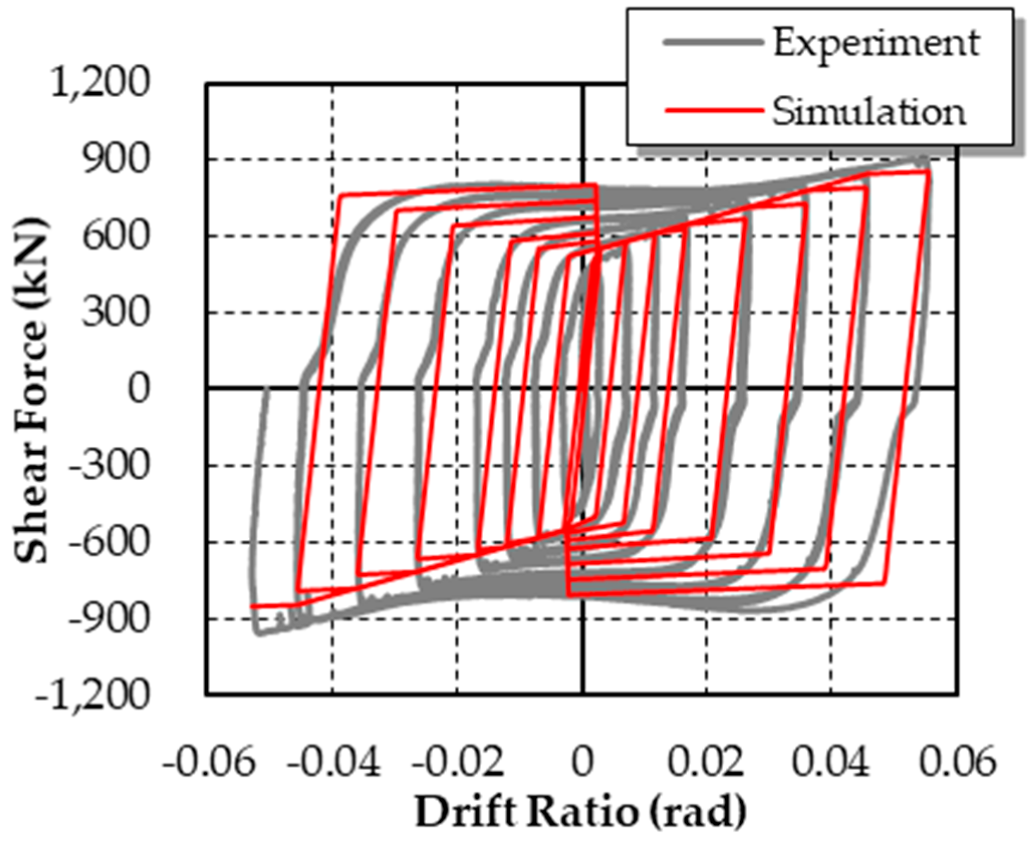
Comparison of the hysteretic curves of the shear link.

Figure 8.
Repeating open and closed joint. (a) Joint opening; (b) joint closed.

Figure 9.
Column axis coordinates at maximum lateral displacement.

Figure 10.
Different spring models. (a) Uniformly distributed spring model; (b) integrated spring model.
Figure 10.
Different spring models. (a) Uniformly distributed spring model; (b) integrated spring model.

Figure 11.
Results of different spring models.

Figure 12.
Parameters of the double-column self-centering pier with shear links.

Figure 13.
Simplified model of double-column self-centering pier with shear links. (a) Full structure; (b) semi-structure.
Figure 13.
Simplified model of double-column self-centering pier with shear links. (a) Full structure; (b) semi-structure.

Figure 14.
Rigid-body displacements of the pier.

Figure 15.
Results of the theoretical and numerical models of the double-column self-centering pier with shear links.
Figure 15.
Results of the theoretical and numerical models of the double-column self-centering pier with shear links.

Figure 16.
Results of the theoretical and numerical models of the double-column self-centering pier without shear links.
Figure 16.
Results of the theoretical and numerical models of the double-column self-centering pier without shear links.

Figure 17.
Influence of the initial stiffness of shear links on the hysteretic curve of the double-column self-centering pier with shear links.
Figure 17.
Influence of the initial stiffness of shear links on the hysteretic curve of the double-column self-centering pier with shear links.

Figure 18.
Influence of the yield strength of shear links on the hysteretic curve of the double-column self-centering pier with shear links.
Figure 18.
Influence of the yield strength of shear links on the hysteretic curve of the double-column self-centering pier with shear links.

Figure 19.
Influence of the initial prestress of steel strands on the hysteretic curve. (a) Double-column self-centering pier with shear links; (b) double-column self-centering pier without shear links.
Figure 19.
Influence of the initial prestress of steel strands on the hysteretic curve. (a) Double-column self-centering pier with shear links; (b) double-column self-centering pier without shear links.


Table 1.
Parameters in finite element (FE) models.
| Parameters | Pier with Shear Links | Pier without Shear Links | |
|---|---|---|---|
| Geometrical dimensions | Height of columns, h | 10.0 m | |
| Cross section of columns, Acol | 2.0 m × 2.0 m | ||
| Distance between columns, d | 3.0 m | ||
| Area of steel strands, APT | 12,737.8 mm2 | ||
| Material properties | Elastic modulus of concrete, Ec | 3.6 × 10⁴ MPa | |
| Axial compressive strength of concrete, fc | 38.5 MPa | ||
| Elastic modulus of steel strands, EPT | 1.95 × 10⁵ MPa | ||
| Ultimate strength of steel strands, fPT | 1860 MPa | ||
| Gravitational forces | Gravity of superstructure, Wss | 3.08 × 10⁴ kN | |
| Gravity of columns, Wcol | Ignored | ||
| Shear links | Initial stiffness of shear links, kSL | 1.6 × 10⁴ kN/m | / |
| Yield strength of shear links, FySL | 2.0 × 10⁴ kN | / | |
| Other | Initial prestress of steel strands, FPT0 | 1.54 × 10⁴ kN | |
© 2019 by the authors. Licensee MDPI, Basel, Switzerland. This article is an open access article distributed under the terms and conditions of the Creative Commons Attribution (CC BY) license (http://creativecommons.org/licenses/by/4.0/).
Share and Cite
MDPI and ACS Style
Xu, L.; Lu, X.; Zou, Q.; Ye, L.; Di, J. Mechanical Behavior of a Double-Column Self-Centering Pier Fused with Shear Links. Appl. Sci. 2019, 9, 2497. https://0-doi-org.brum.beds.ac.uk/10.3390/app9122497
AMA Style
Xu L, Lu X, Zou Q, Ye L, Di J. Mechanical Behavior of a Double-Column Self-Centering Pier Fused with Shear Links. Applied Sciences. 2019; 9(12):2497. https://0-doi-org.brum.beds.ac.uk/10.3390/app9122497
Chicago/Turabian StyleXu, Liangjin, Xinzheng Lu, Qiaoshan Zou, Lieping Ye, and Jin Di. 2019. "Mechanical Behavior of a Double-Column Self-Centering Pier Fused with Shear Links" Applied Sciences 9, no. 12: 2497. https://0-doi-org.brum.beds.ac.uk/10.3390/app9122497
Note that from the first issue of 2016, this journal uses article numbers instead of page numbers. See further details here.