Thermoeconomic Analysis of Different Exhaust Waste-Heat Recovery Systems for Natural Gas Engine Based on ORC


1
Departamento de Ingeniería Mecánica, Universidad del Atlántico, Carrera 30 Número 8-49, Puerto Colombia 080007, Colombia
2
Facultad de Ingeniería Mecánica, Universidad Pontificia Bolivariana, circular 1a 70 -01, Medellín 050004, Colombia
*
Author to whom correspondence should be addressed.
Appl. Sci. 2019, 9(19), 4017; https://0-doi-org.brum.beds.ac.uk/10.3390/app9194017
Submission received: 18 August 2019
/
Revised: 7 September 2019
/
Accepted: 12 September 2019
/
Published: 25 September 2019
(This article belongs to the Special Issue Engineering Thermodynamics)
Abstract
:Waste-heat recovery (WHR) systems based on the organic Rankine cycle (ORC) improve the thermal efficiency of natural gas engines because they generate additional electric power without consuming more gas fuel. However, to obtain a cost-effective design, thermoeconomic criteria must be considered to facilitate installation, operation, and penetration into real industrial contexts. Therefore, a thermo-economic analyses of a simple ORC (SORC), ORC with recuperator (RORC) and a double-pressure ORC (DORC) integrated with a 2 MW Jenbacher JMS 612 GS-N. L is presented using toluene as the organic working fluid. In addition, the cost rate balances for each system are presented in detail, with the analysis of some thermoeconomics indicator such as the relative cost difference, the exergoeconomic factor, and the cost rates of exergy destruction and exergy loss. The results reported opportunities to improve the thermoeconomic performance in the condenser and turbine, because the exergoeconomic factor for the condenser and the turbine were in the RORC (0.41 and 0.90), and DORC (0.99 and 0.99) respectively, which implies for the RORC configuration that 59% and 10% of the increase of the total cost of the system is caused by the exergy destruction of these devices. Also, the pumps present the higher values of relative cost difference and exergoeconomic factor for B1 (rk = 8.5, fk = 80%), B2 (rk = 8, fk = 85%).
1. Introduction
Energy efficiency is seen as a promising technology for reducing energy-generation costs and has become the best hope for controlling climate change [1,2]. Therefore, it is necessary to propose methodologies for the rational use of energy in waste-heat recovery systems (WHRS) in stationary generation engines, which are widely used in the industrial sector [3,4].
The thermal efficiency enhancement of industrial engine requires a cost-effective thermal design of WHRS configurations. Thus, it is necessary to evaluate project costs looking forward to achieving a proper cost-efficiency ratio [5]. The total investment costs have been evaluated for the suggested ORC systems, allowing the development of a thermal-economic analysis [6], but the natural gas engine has not been considered. Total investment capital (TCI) has been studied in some research results, involving the operation and maintenance (O&M) costs, but the heat source is a thermal oil without taking into account the thermal conditions of the engine exhaust gases [7].
The tendency in research related to exergoeconomic analysis increased exponentially from 2015 to 2017, based on thermodynamic models such as that proposed by Karellas and Braimakis [8] using biomass fuel and solar power as a heat source, where an economic analysis of a micro-scale trigeneration system was conducted to produce combined heat, electricity, and refrigeration, operating combined with an organic Rankine cycle (ORC) and a vapor compression cycle. The three systems were connected to the same shaft, obtaining, as a result, electricity production of 1.42 kWe, heat power of 53.5 kWh, the net electrical efficiency of 2.38%, and a net electrical efficiency of 2.38%, while the energy efficiency of the ORC was estimated at around 7%.
In addition, the development of multi-generation energy systems based on geothermal energy has achieved optimizations of the system by coupling heat recovery cycles, as proposed by Akrami et al. [9], including an ORC for electricity generation and heating, performing an energetic, exergetic and exergoeconomic analysis of the system to achieve an energy and exergetic efficiency of 34.98% and 49.17%, respectively. However, the study is limited to a simple ORC configuration in a geothermal application, so the results cannot be expandable for waste-heat recovery (WHR) in the natural gas engine. Therefore, because of the moderate studies carried out on natural gas engine modeling to characterize the exhaust gas flow and temperature, few studies are available in the literature considering the WHR based on the ORC from these types of stationary engine [10].
On the other hand, WHR with on-board ORC systems from vehicle engines, has also been developed, where through simulations of the performance of a high-resistance truck, truck/engine and ORC/cooling system models were conducted and experimentally validated. The results presented reveal the effects of the truck engine speed on its performance with the ORC system, and the truck engine has a power gain of 3.07 kW at the speed of 95 km/h under full load conditions [11].
The most recent applications of ORC for WHR have focused on determining the technical feasibility of the integration of an ORC to diesel engines, not gas engines, without evaluating the effect of engine operating parameters on the economic viability of the integrated generation system, but they lack a detailed exergoeconomic analysis [12,13,14]. However, it is necessary to highlight the research carried out with the diesel engine WP12 336E40, which produced 247 kW at 1400 rpm. The study evaluated different working fluids such as R600, R600a, R601a, R245fa, R1234yf, and R1234ze in a simple configuration, where the evaporation pressure, condenser temperature, exhaust temperature at the outlet of the evaporator and degree of overheating were studied and optimized by means of a thermoeconomic analysis, in which a recovered power was ranging from 5.2 kW to 13.2 kW for the working fluids [15].
Subsequently, research conducted in 2017 was developed for a simple ORC and ORC with recuperator configuration as a WHR from a V12 stationary diesel engine, which produces 1500 kW at 1500 rpm, and exhaust gas temperatures between 466.8°C and 484.5 °C, using different working fluids such as acetone, n-hexane, n-octane. Toluene, ethanol, and MDM. Both cycles use a thermal oil heat exchanger which is the proposed in this study, and the backpressure effect of the bottoming cycle is studied in simulation allowing to find a reduction of specific brake fuel consumption of 17.7 g/kWh and 19.7 g/kWh [16].
In this sense, to improve the thermoeconomic indicators, an ORC cycle with a screw expander was evaluated in 2018 integrated to a marine diesel engine ZLC-6210-5 with 6 cylinders in line that produces 662 kW at 750 rpm. The results allowed the recovery of power of R11 (83.6 kW), R141b (97 kW) and cyclohexane (97.8 kW), where a thermoeconomic analysis was carried out for the variables evaporating temperature and pressure ratio at an exhaust gas temperature of 340 °C [17].
Recently, a thermal evaluation was performed only for a simple ORC cycle, where bioethanol from selected microalgae was evaluated as working fluid in the operation of a 6 cylinder in-line marine diesel engine, which generates 996 kW at 1500 rpm, obtaining recovered power of 5.1 kW [18].
The main contribution of this research is the present thermoeconomic analysis of WHR configurations as bottoming cycles of a 2 MW natural gas engine, where an exergetic analysis is combined with economic considerations, in order to determine the design of each system with the best cost-efficiency ratio [19,20]. Each of the exergy flows, exergy losses, and exergy destruction rates are assigned with their costs to identify those unprofitable processes, and therefore to propose the appropriate modification of the system to achieve the best economic performance, through the analysis of the variables that influence the exergy performance of the systems, such as the relative cost [21,22], exergoeconomic factor [23], and the cost rates of exergy destruction and exergy loss [24]. These indicators enable to evaluate the viability and feasibility of implementing the proposed configurations in the different engine operating conditions.
2. Methodology
2.1. System Description
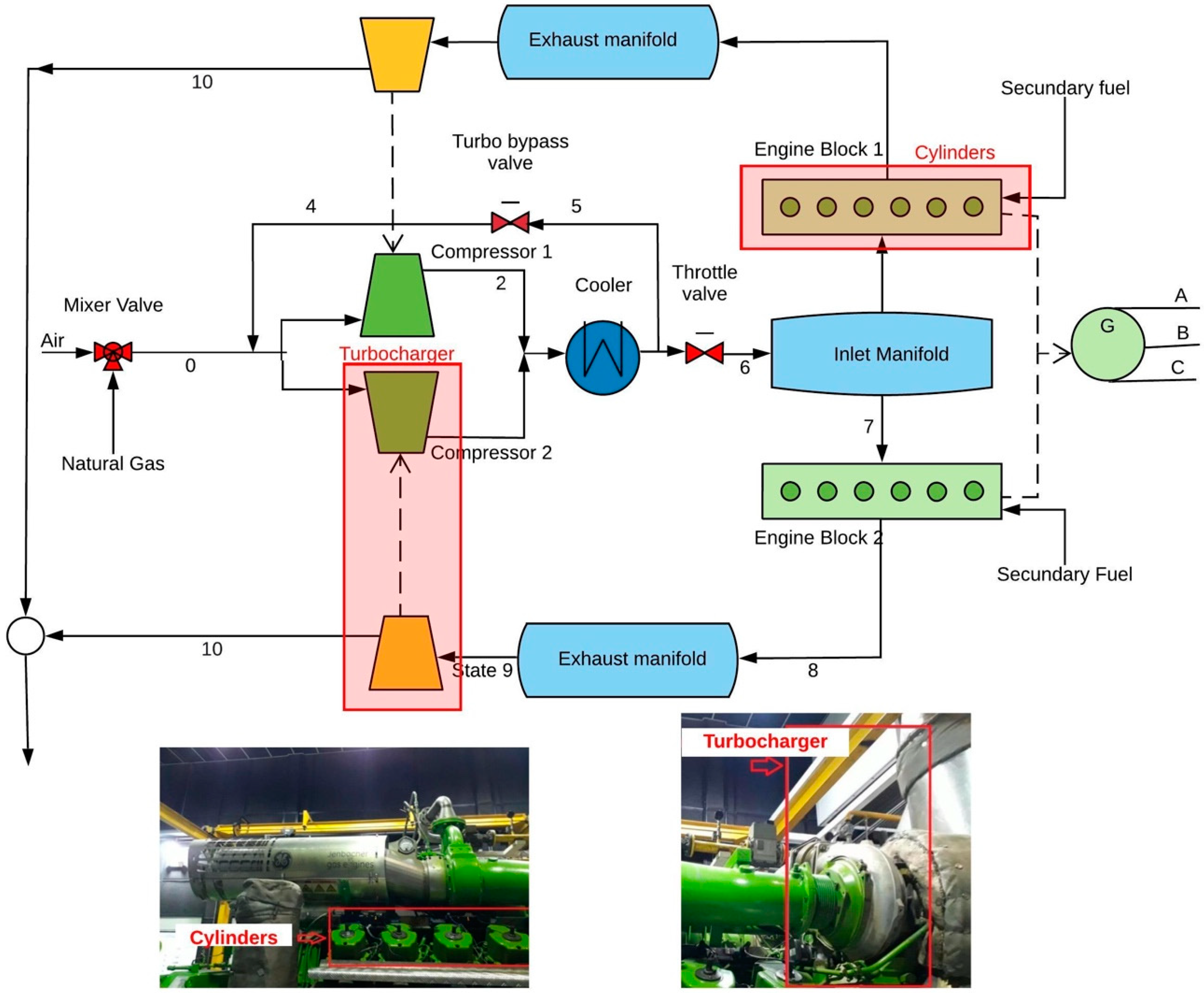
The prime mover studied in this paper is the GE Jenbacher type 6 engine for power generation, working at a frequency of 60 Hz which constant revolutions of 1500 RPM on the crankshaft to ensure the proper voltage waveform.
The physical structure of the Jenbacher JMS 612 GS-N. L is shown in Figure 1. This engine has been widely used for autogeneration purposes worldwide and is installed in a plastics company in the city of Barranquilla, Colombia, without any WHR system, with an effective efficiency of 38.58%, the average value of all engines of this type currently operating in Colombia. The engine regulates by means of the throttle valve (state 6) and the turbo bypass valve (state 4) the supply of the natural gas mixture to the engine cylinders, to operate between a minimum load of 1000 kWe and a maximum load of 1982 kWe, with an air/fuel ratio of 1.79 and 1.97, respectively, generating exhaust gases (state 8) in each of its 12 cylinders with a temperature ranging from 580 °C to 650 °C. These gases are expanded in the turbocharger turbines to obtain residual gases (state 10) that are emitted into the environment.
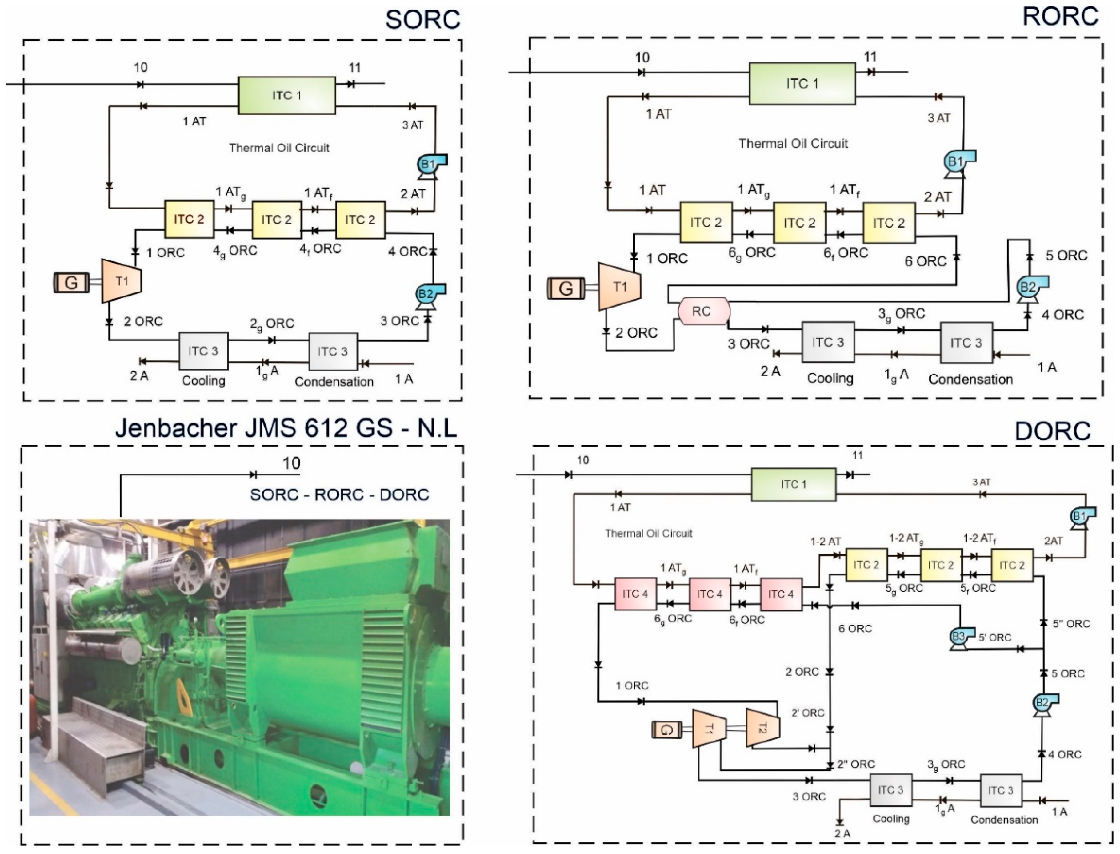
To take advantage of the thermal availability of the waste gases (state 10), the simple ORC (SORC), ORC with recuperator (RORC) and double- pressure ORC (DORC) configurations have been adopted to generate additional power as shown in Figure 2 [7,10,25,26]. The determination of the operating conditions and thermoeconomic analysis of the SORC, RORC and DORC configurations, including the thermal oil secondary circuit, is performed for a real operating context of the engine under study. In the most frequent operating condition, the input values are gas flow (120 L/min), λ (1.784), engine revolution (1482 rev/min), gas pressure (1163.6 mbar), throttle valve (80%), turbo bypass valve (9.1%), gas temperature (389 °C) and engine coolant temperature (63.9 °C), and the outputs are mechanical engine power (1758.77 kW), with an effective engine efficiency (38.59%), heat recovery efficiency (40.78%), heat removed from exhaust gases (514.85 kW) and specific engine fuel consumption (177.65 g/kWh) [10,27,28].
2.2. Thermodynamic Modeling
The energy and exergy modeling of the SORC, RORC, and DORC configurations as the waste-heat recovery bottoming cycle was developed [10]. Cyclohexane was selected as the working fluid, considering the cost-effective performance in this system integrated with the gas engine. The parameters considered to study the systems in the configurations were isentropic efficiency turbines (80%) [28], isentropic efficiency pumps (75%) [28], cooling-water temperature in stream T1A (50°C), pinch-point condenser (15 °C), pinch point evaporators ITC2 and ITC4 (35 °C) and effectiveness in the recuperator (85%) [28]. Pressure ratios in B1 of (2.5) and B2 (30) were considered in the SORC and RORC systems, while in the DORC the pressure ratios were B1 (11.09), B2 (20) and B3 (9).
All the equipment of the systems was studied in steady-state condition according to the mass conservation law, as shown in Equation (1), and the energy balance shown in Equation (2). The thermodynamic model of the WHR systems was developed applying the mass balance (Equation (1)) and the energy balance (Equation (2)) to each component in a steady-state condition.
where is the mass flow rate, the working fluid specific enthalpy, is the energy transfer by heat and is the power rate.
The specific physical exergy for all the stream was calculated by the mean of the Equation (3), which the change of kinetic and potential energy was not considered, while the chemical exergy (Equation (4)) was only evaluated in the exhaust gases line from the natural gas engine (stream 10).
where enthalpy , and entropy were evaluated at the reference temperature (298.15 K) and pressure (101.3 kPa) conditions.
R represents the universal gas constant, and the gas molar fraction. From the exergies calculated for all thermodynamic states, the exergy balance (Equation (5)) to each equipment of the WHR systems was conducted.
where is the stream exergy at the inlet, the stream exergy at the outlet and is the exergy destruction of each component.
2.3. Validation
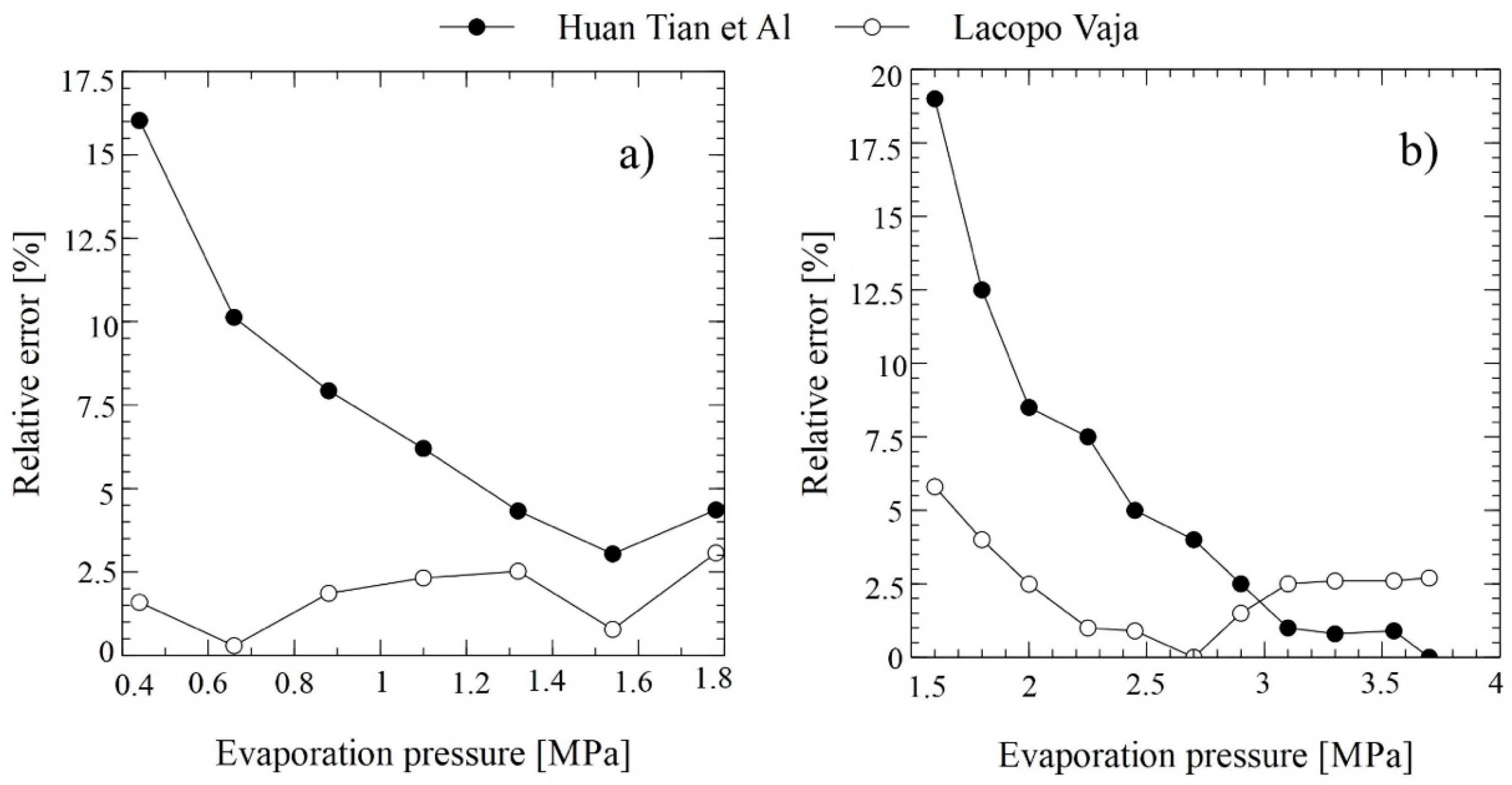
To validate the RORC model, the evaporation pressure was evaluated from 0.8 MPa to 5.5 MPa, and the operational conditions were set in pump efficiency (80%), turbine efficiency (70%), thermal oil temperature in stream 1AT (250 °C), condenser temperature (35 °C), evaporator pinch point (30 °C). The results of the thermal efficiency were compared with the research performed by Lacopo [29] and Huan Tian et al. [30], using the R-11 and R-134a as working fluids. The results of the thermal efficiency error obtained for both fluids are shown in Figure 3.
The model developed in this article shows results very close to those obtained by Lacopo [29] and Huan Tian et al. [30] in the same SORC configuration. The simulated results show that in the evaluated range there was a relative error around 3% for R-11 when comparing the thermal efficiency results with those of Lacopo [29], while using R-134a as working fluid, the maximum relative error presented was about 6% for an evaporating pressures lower than 1 MPa, while values higher than 2 MPa imply a relative error that is approximately 3%, which is a consequence of the methodology used to calculate the thermodynamic properties of the organic working fluid; also, the error value obtained is an acceptable estimation to conduct the thermoeconomic analysis. On the other hand, in the range of 2.5 MPa to 3 MPa, which is the cycle evaluated in this study, the relative error only reaches values of 1% with respect to the work of Huan Tian et al. [30], which shows the correct thermodynamic analysis of the system.
The RORC model was validated comparing the results with a WHR application from a geothermal system [31,32], whose operational parameters are shown in Table 1. The parameters used to validate the system model were a pump efficiency (95%), turbine efficiency (89%), exhaust gas temperature (165 °C), condenser temperature (15 °C), evaporator pinch point (10 °C) and the evaporator pressure (0.31 MPa).
From the values in the relative errors of the proposed model with respect to the two thermodynamic models in the literature [31,32], there is a close relationship between them, which allows this model to be used to conduct studies and performance evaluations in different conditions of operation. When evaluating isobutane as an organic working fluid, errors in thermal efficiency of 0.73% and 0.62% were presented regarding the works of R. S. El-Emam et al. and V. Zare respectively, while the estimation of the exercise efficiency presented errors of 0.18% and 0.35% respectively, which guarantees the correct development of the model and the possibility of using this configuration for the evaluation of WHR alternatives.
3. Exergoeconomic Analysis
3.1. Economic Analysis
The analysis of the total cost of production (TPC) of WHR systems from exhaust gas generation engines through different configurations of ORC consists of estimating both the total capital to be invested (TCI), as well as the operation and maintenance costs (O&M), as shown in Equation (6), which have not been extensively addressed in the literature [33].
where the TCI of ORC heat recovery systems is calculated using Equation (7) [34].
FCI represents the fixed cost investment of the thermal system, which quantifies the direct costs (CD) and associated indirect costs (IC), as shown in Equation (8).
The other costs (Equation (9)) consider the start-up costs (SUC) represented by the start-up of the equipment, the initial working capital of the thermal system (WC), the costs associated with research and development activities (LRD), and the costs associated with the provision of funds during construction (AFUDC).
The CD are the costs corresponding to the acquisition of equipment, piping and accessories (31% from the TCI), installation and assembly (20%), instrumentation and control (10%), and electrical equipment and materials corresponding to the system (11%), civil adequation (45%) and work area (10%). For the heat exchangers, the pump and the turbine were correlated in Table 2, according to turbine output power, pump power and heat exchanger area, considering technical data from manufacturers and calculating costs in US dollars [31,32,35].
In addition, the IC are those related to engineering and supervision (30%), and the construction of equipment (15%), which are expressed in terms of the acquisition costs equipment [36].
For the complete economic analysis of the WHR configurations other costs corresponding to the assembly operation, commissioning (10%), working capital (10%), licensing and development costs, and the funds used during the construction of the system (15%) also have to be evaluated. In addition, in the direct costs are considered the supervision (15%), parafiscal expenses (35%), maintenance (6%), and direct miscellaneous costs (15%).
Capital expenditures for active assets decrease while fuel and O&M costs increase with the years of operation. Thus, the leveled values of these costs are obtained by calculating the constant escalation levelization factor (CELF) using Equation (10), which links the calculation of the cost of the first year of life of the project to an equivalent annuity [34].
where n is the project lifetime, is calculated with Equation (11) as a function of the annual effective cost rate, and the capital recovery factor CRF is calculated through Equation (12).
is the nominal scaling ratio, and is the annual interest rate. The economic data assumed for the thermoeconomic modeling are presented in Table 3.
3.2. Exergy Cost Balance and Thermoeconomic Indicators
The Specific Exergy Costing (SPECO) cost method consists of three steps [34]. In the first step, the exergy flows are identified, for which a process flow diagram is made where the exergetic inputs and outputs flows are known due to exergetic analysis. In the second step, the different flows between the inputs and outputs are defined for the performance evaluation of each component of the process. Then, in the third step, the cost balances and auxiliary equations are presented, which are presented in Table A1.
The cost of a k-component is the sum of the costs due to the capital investment and the operation and maintenance costs , as shown in Equation (13).
The exergetic costs balance for control volumes in the stationary state is made by means of Equation (14), which establishes that the total cost of the exergetic output flows, is equal to the cost of the exergetic inlet flow plus the capital costs and other costs [32].
The exergetic balances obtained by applying Equation (14) to each of the components of the different WHR systems using ORC are shown in Table A1. The total exergy cost of a flow can be defined as shown in Equation (15).
where the term is the leveled cost per unit of exergy. For the analysis of ITC1 and ITC 3 in the WHR based on SORC and RORC, the costs per unit of exergy of stream 11 and 1A are null, because they have negligible purchase and sale costs.
The cost rates associated with the input and output are defined in a similar way to the exergy rates, which were presented previously for each WHR configuration [10]. The cost rates obtained are used to calculate the average costs per unit of input and output flow for each component, according to the methodology defined by Bejan [34]. For component k of the WHR system, the cost associated with the fuel is calculated using Equation (16), while the cost associated with the product is calculated using Equation (17).
The cost rates of exergy destruction and exergy loss are fundamental values for the thermoeconomic optimization of the systems under study. The costs of exergy destruction for a component of the system are not involved in the cost balances, so it is usually associated with a hidden cost. The costs associated with the destruction and loss of exergy is calculated through Equations (18) and (19) [34].
In these equations, it is assumed that the average fuel exergy cost remains constant with a variable amount of exergy destruction or exergy lost. Thus, it could be assumed that this is the specific exergy cost of the product, and not of the fuel that remains constant.
On the other hand, the relative cost difference for a system component () is calculated by means of Equation (20) and determines the increase in the unit exergy cost between the product and the fuel in relation to the unit cost of the input [34].
This thermoeconomic indicator makes it possible to determine the inefficient components in the system, which have a great influence on the cost of the system and together with the exergoeconomic factor are used for thermoeconomic analysis and optimizations of the processes [31].
The exergoeconomic factor calculated by Equation (21) determines that part of the increase in the cost rate of the component explicated by the exergy destruction or exergy loss, and the portion which is associated with the cost of purchasing and maintaining the equipment. The comparison of these values for a given component allows proposing an optimal balance between the efficiency of the component and the investment cost [34]. The results of the relative cost and the exergoeconomic factor for each of the proposed configurations are shown in the following section.
4. Results and Discussions
The cost rates associated with the exergy values of the streams of WHR systems are presented in Table 4. This table shows that the specific cost rate of the toluene stream at turbine inlet (1ORC) is calculated to be 19.11 USD/GJ for the ENGINE/SORC and 16.26 USD/GJ for the ENGINE/RORC, and it is 18.16 USD/GJ for the ENGINE/DORC. The value of the cost rate of toluene organic fluid at ORC turbine, which is the device to produce power is determined to be 3.23·10−3 USD/s, 4.43·10−3 USD/s and 2.89·10−3 USD/s for ENGINE/SORC, ENGINE/RORC and ENGINE/DORC, respectively.
Furthermore, Table 5 indicates that the ITC3, B1, and B2 fuel cost rate has an important contribution to the power production cost of the WHR configurations. The product cost of the B1 is found to be 1700.64 USD/GJ, which mean the highest cost difference presented in the process, due to the large pressure ratio required to operate the thermal oil and overcome the drop pressure in the hydraulic loop.
The results show that a high level of capital is being invested compared to the rest of the equipment to obtain intermediate products in the system, such as the cost of thermal oil product in B1 in all the configurations being SORC (1700.64 USD/GJ), RORC (996.78 USD/GJ) and DORC (302.03 USD/GJ), and the cost of the organic fluid product in B2 being SORC (197.64 USD/GJ), RORC (161.52 USD/GJ) and DORC (201.58 USD/GJ). Related to the exergy rate of the products, it can be affirmed that this is low for these components, so the exergetic efficiency must be improved to achieve the same results at a lower cost. Table 6 shows the destruction and exergy loss costs for the WHR systems.
Table 6 shows that the condenser (ITC 3) has the highest value of ĊD among the other components in the SORC and RORC configuration, while in the RORC was the high-pressure evaporator heat exchanger (ITC 4). The f value of the ITC3 component is 18% (SORC) and 41% (RORC) as shown in Table 7, which indicates that the exergy destruction cost in this component dominates the purchase and operating cost. Therefore, this heat exchanger with a f value of 99% means in the DORC a great opportunity to optimize the size of equipment to reduce the purchase cost.
After the ITC3, the ITC1 has the highest value of ĊD in the SORC configuration. The relatively low value of f in this equipment means that the cost rate of exergy destruction of the ITC1 is considerably higher than the purchase and operating cost rate for it, as a consequence of the large temperature difference between the thermal oil fluid and the exhaust gas from the engine. Therefore, another type of organic fluid should be studied in high-temperature ORC applications, and the selection of more expensive equipment will improve the exergoeconomic performance of these solutions. An alternative to evaluate is to design a heat exchanger with a relative higher heat transfer area, due to the greater value of exergy destruction in the ITC1 mainly due to the temperature differences between the streams, and the technical restriction of the thermal oil operational temperature.
The results presented in the relative cost difference and exergoeconomic factor by system components are shown in Table 7.
The exergoeconomic factor and exergy efficiency for the GT-MHR turbine is found to be almost 55% and 97%, respectively, in all three combined cycles. Therefore, the exergy and exergoeconomic performance of this component are satisfactory. Considering the lower values of power production by the ORC turbine, its contribution to the total system cost will be low.
The relatively higher value of ĊD and the very low value of f for the HP and LP compressors suggest that greater capital investments are appropriate, i.e., higher values of the pressure ratio and isentropic efficiency.
The precooler, intercooler, and condenser of the combined cycles have low values of the exergoeconomic factor. Therefore, increasing the capital investment of these components is suggested from the exergoeconomic viewpoint.
From the results it can be observed that the pumps present a high relative cost difference, which together with the fact of having a low exergy destruction compared to the other components of the system and the higher values of the exergoeconomic factor, make that the investment of the costs is not effective to obtain the product of these equipments.
4.1. Sensitivity Analysis
4.1.1. Cost Rate of Exergy Destruction
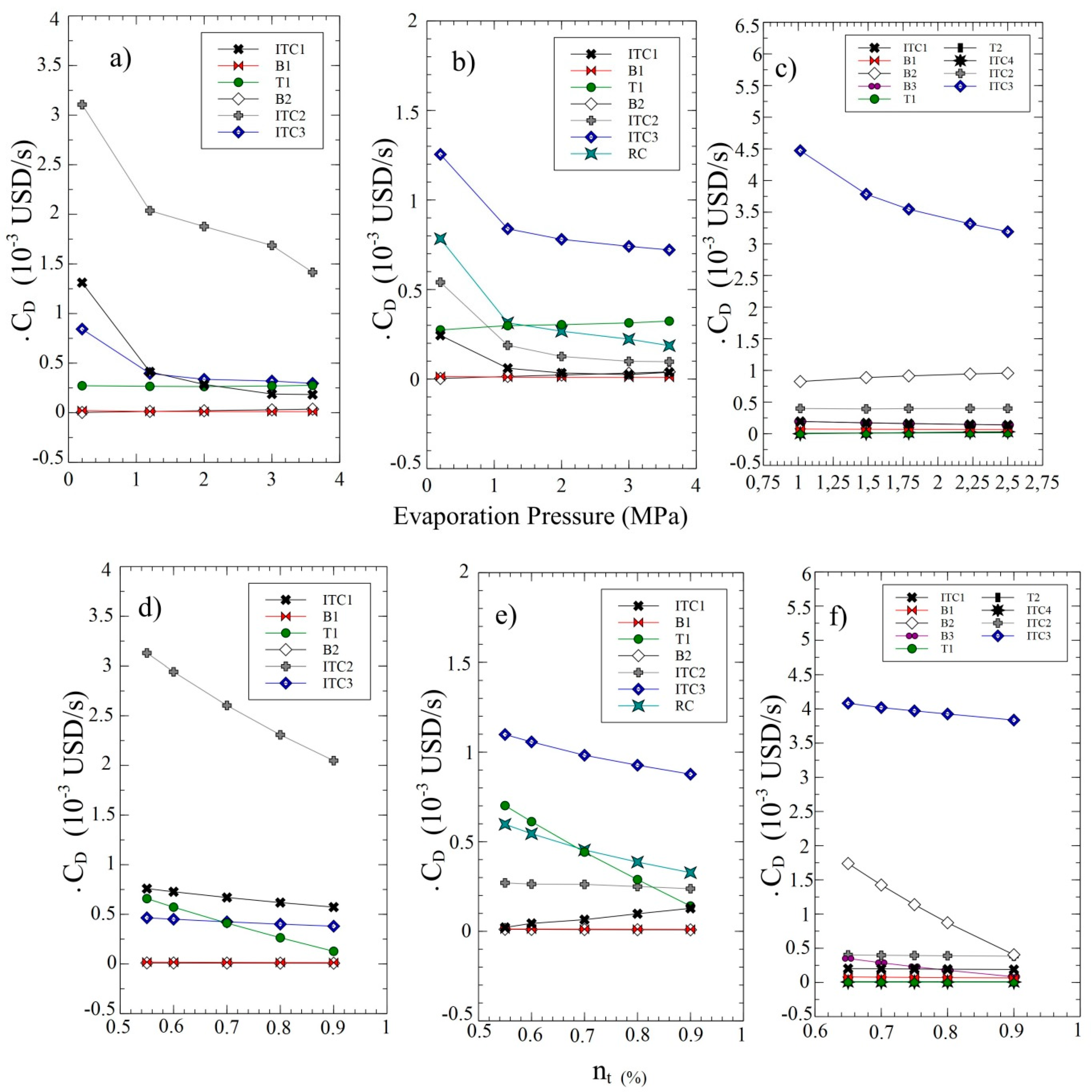
The effect of the evaporating pressure on the costs of exergy destruction for the components in the three configurations evaluated is shown in Figure 4. For heat exchange equipment, especially evaporators, the cost rate of exergy destruction shows a significant decrease as evaporating pressure increases, which is due to the decrease in heat transfer irreversibilities. This phenomenon suggests the existence of an optimal operating condition in terms of evaporating pressure in order not to incur high-pressure ratios without an increase in the energy generated by the system. The cost rate of exergy destruction for evaporators decreases in a small range from 0 MPa to 1 MPa and is maintained with an asymptotic tendency for pressures up to 4 MPa.
The increasing turbine efficiency is reflected in greater net power generated, as well as an increase in the overall exergetic efficiency of the system. However, these variations are such that the net effect is a decrease or constant behavior on the cost rate of exergy destruction for all components of the SORC and DORC configuration as shown in Figure 4d,f respectively. A percentage decrease of 80.6% in the cost of exergy destruction for the RORC configuration was presented for the turbine, as the efficiency of the turbine increased occasionally. This is mainly due to a considerable decrease in the destroyed exergy of the turbine, which constitutes about 18.1% of the total destroyed exergy of the RORC configuration. This trend is the same for the three configurations studied.
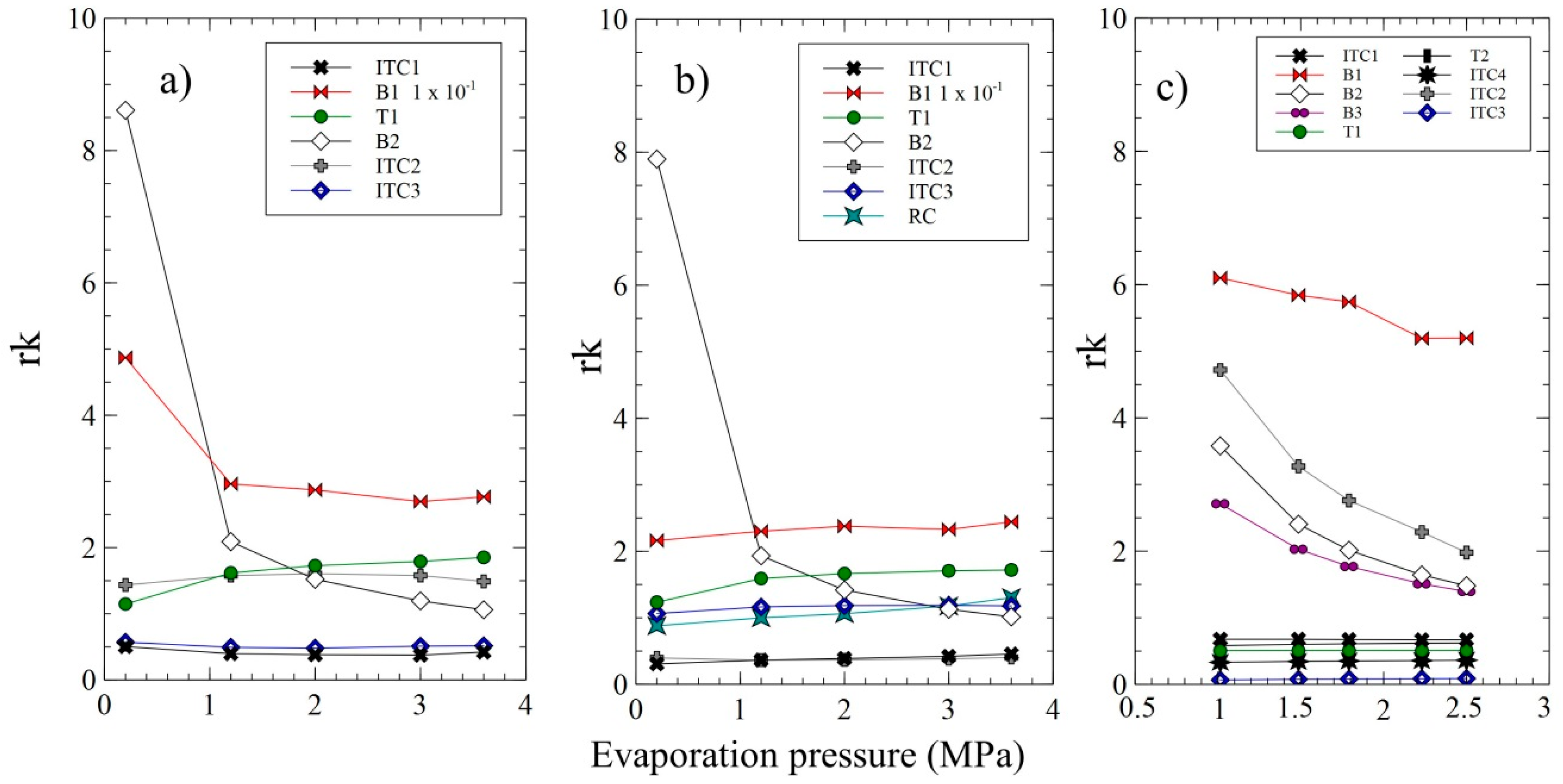
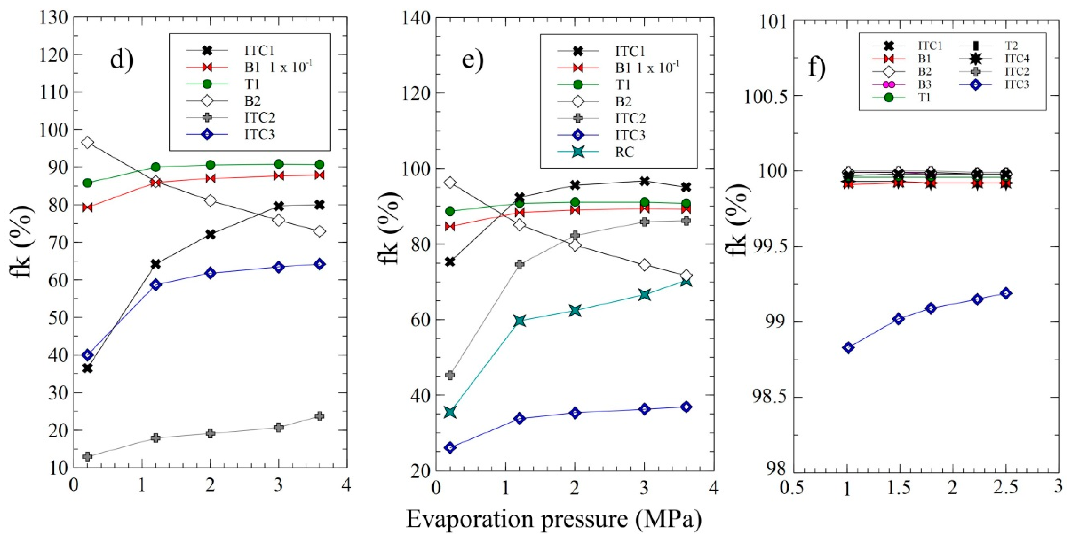
4.1.2. Relative Cost Difference and Exergoeconomic Factor Analysis
Figure 5 shows the effect of the evaporating pressure on the relative costs difference by components for each WHR system. Figure 5a shows the decrease in the relative cost of B2 and ITC1 by increasing the evaporating pressure from 0 MPa to 1 MPa. However, these two components have lower relative costs to higher pressures, which is because the cost values of exergy destruction, investment costs, operation, and maintenance are significantly higher than the product cost of exergy. A similar case happens for ITC 3 and the recuperator in the RORC, as shown in Figure 5b. In the DORC case, as shown in Figure 5c, ITC2, B1, B2, and B3 show the highest relative cost values associated with the exergy destruction. However, these components present a relative cost decrease of 139%, 17%, 142%, and 95% respectively, which confirms that this parameter allows a better exergetic performance only of these components since they do not significantly affect the overall thermoeconomic performance of the configuration. Likewise, the results show that the specific cost of exergy in the ITC 1 and condenser in the three WHR systems maintains a constant value in the vaporization pressure range studied, which can be explicated because of the exergy loss do not take excessively large values.
The high values of relative cost difference and exergoeconomic factor for B1 (rk = 8.5, fk = 80%), B2 (rk = 8, fk = 85%) and T1 (rk = 1, fk = 85%) at a pressure of 0.2 MPa, in the SORC as shown in Figure 5a,d, are due to the high purchase, operation and maintenance costs that make the proposed WHR system more expensive. Therefore, in the case of pumps, the possibility of purchasing ones that cause less increase in the exergy unit by sacrificing the value of the exergetic efficiency should be evaluated.
For the RORC configuration, the ITC2, ITC3, and RC heat exchanger equipment have lower exergy destruction cost-plus purchase values than T1, so operation at a different evaporating pressure will not significantly influence the overall performance of the system. The high costs in the condenser and its increase in evaporating pressure are associated with a high value of exergy destruction, in addition to the inefficiencies of the heat exchange process at the end of the process. An important feature is that exergetic losses are not attributed exclusively to one component of the system; it is in this device where there are the highest exergetic losses and the highest values of exergy loss costs. In addition, being a device located in the final part of the process, the unitary exergetic cost considered for its valorization is very high. Regarding the exergoeconomic factor, the values of the condenser and the evaporator are 20% and 45% at a pressure of 0.2 MPa respectively as shown in Figure 5e, which are the lowest in the proposed configuration, so that the exergetic unit does not become excessively expensive when passing through these devices in relation to the others in the process.
Figure 5f shows the influence of the evaporation pressure for each of the components of the DORC configuration, where the exergoeconomic factor takes values close to 100% for all the components, which shows that the purchase costs of the equipment are more relevant than the cost rate for the exergy destruction and exergy loss, and the costs associated with the maintenance of the equipment. Therefore, the savings potential of these WHR systems depends on the operating conditions of each component and the operation of the gas engine.
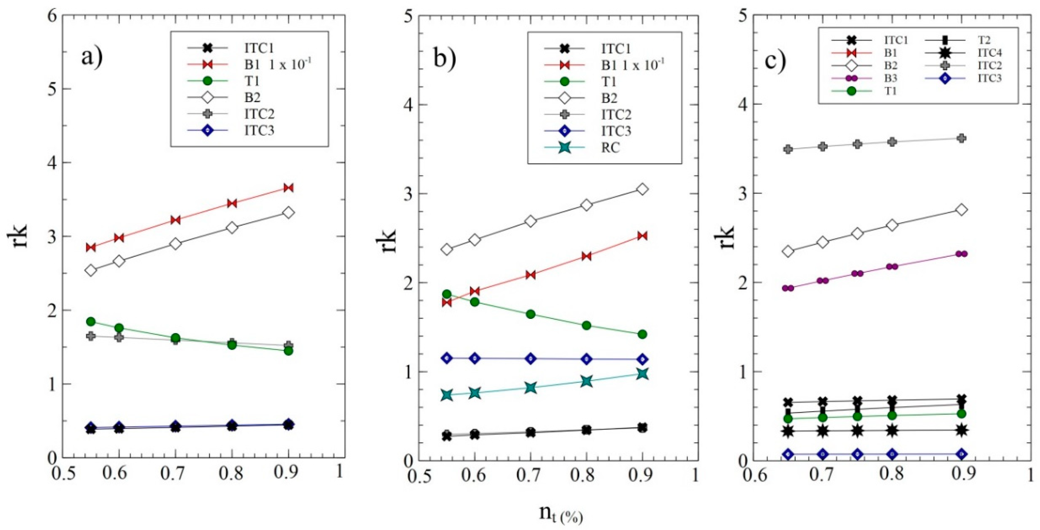
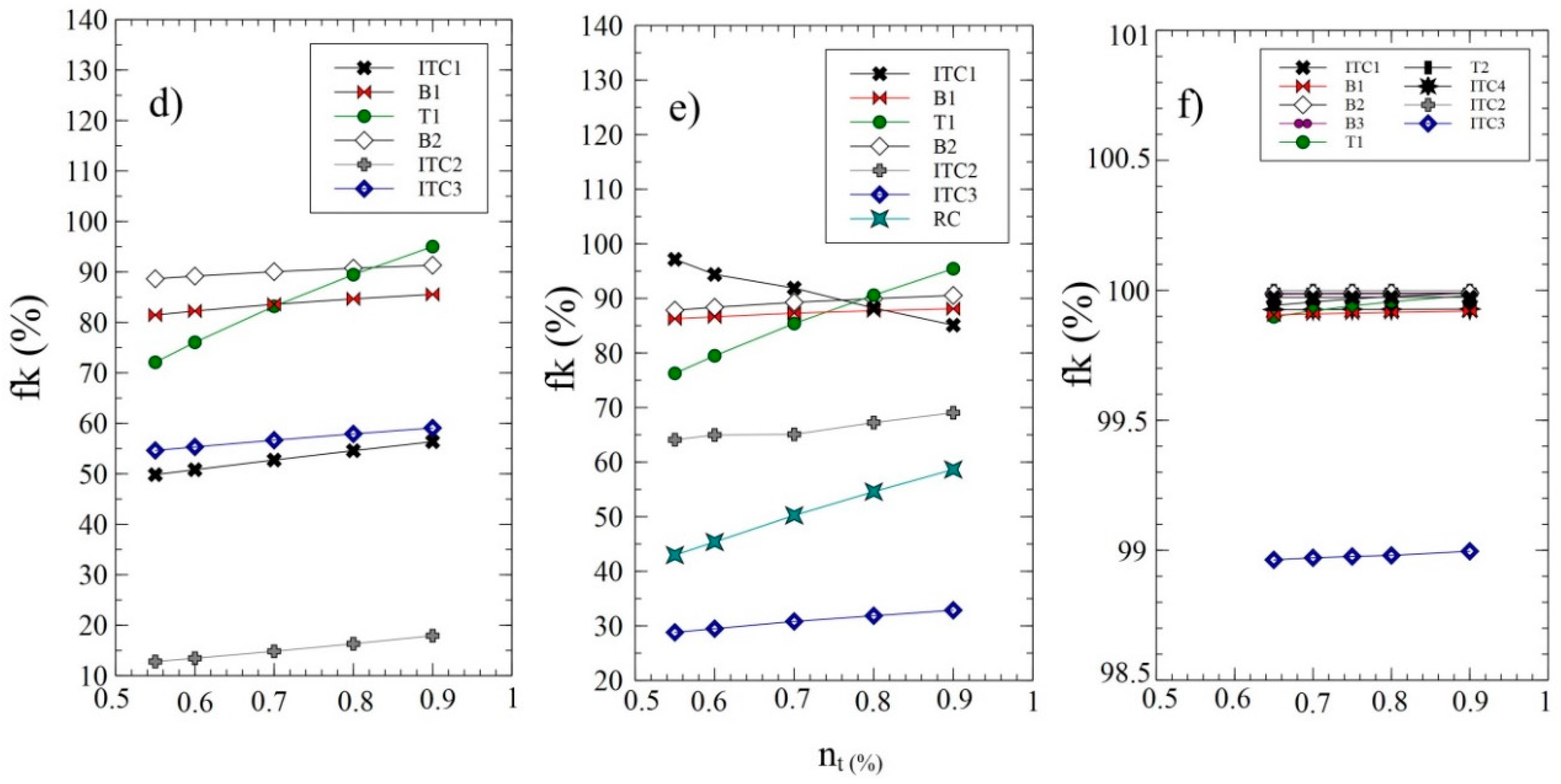
It should be noted that although an increase in turbine efficiency increases the power generated in the three WHR configurations, this also causes an increase in the turbine purchase cost by requiring more innovative technology, which increases the exergoeconomic factor as shown in Figure 6. Therefore, in practice, a moderate turbine efficiency value is recommended in which the total investment costs of the process present competitive values that facilitate market penetration.
5. Conclusions
The study allowed an energetic and exergetic analysis of three energy-generation systems based on ORC, for waste-heat recovery from the exhaust gases of a 2 MW generation engine using natural gas as fuel in a plastic industry located in the Colombian Caribbean region. In particular, the results obtained through a dynamic model validated with experimental data can be used to determine the exhaust gas temperature, power output, fuel consumption and thermal efficiency of the gas engine based on the mean variables of the system. The study involved the thermodynamic model development and thermoeconomic performance indicator of three WHR configurations integrated with the engine, to improve the thermal efficiency of the Jenbacher JMS 612 GS-N. L.
To identify the location of the improvement opportunities of the thermal system, the irreversibilities, exergy destruction, and exergy destruction cost of the components were studied. The destroyed exergy of all the elements in the different configurations is low compared to the thermal oil pump (B1). These values suggest that reducing the heat transfer area in the evaporator, recuperator, and condenser may provide a favorable solution, especially in the DORC configuration. However, it is essential to note that these plate heat exchangers are manufactured from specialized materials for these applications, which contributes significantly to the total purchase cost of the systems. Also, the operation of this equipment has a significant effect on the total exergy destruction and thermal efficiency of the system as a result of the pinch-point temperature. Therefore, increasing the size of heat exchangers increases the cost of generating electricity.
In the SORC system, the exhaust gases entering the system (state 10) have the most expensive cost per unit of exergy (6.88 USD/GJ), the value of the exergoeconomic factor is approximately 0.18 for the condenser and 0.89 for the turbine. Therefore, the exergoeconomic factor for the condenser and the turbine in the other systems are RORC (0.41 and 0.90), and DORC (0.99 and 0.99), which implies for the RORC configuration that 59% and 10% of the increase of the total cost of the system is caused by the exergy destruction of the condenser and the turbine.
The exergy destruction cost in ITC1 is the most important for the SORC and DORC applications, while the evaporator (ITC2) is the most important for the RORC. Therefore, the effort should be oriented to reducing the exergy destruction in these components. Based on commercial information on the geometric characteristics of the plate heat exchangers and shell and tube heat exchanger, the optimal sizes of these types of equipment for the different configurations should be determined.
On the other hand, the relative cost difference and exergoeconomic factor results in the pumps showed a great improvement opportunity in the SORC configuration. The obtained values for B1 (rk = 8.5, fk = 80%) and B2 (rk = 8, fk = 85%) at the pressure of 0.2 MPa are a consequence of the high acquisition costs, and the operation and maintenance systems that make the proposed WHR system more expensive. Therefore, the possibility of acquiring pumps that cause less exergy increase by reducing the exergetic performance would allow better results for the SORC compared to the RORC.
Author Contributions
Conceptualization: G.V.; Methodology: G.V. and C.I.-R.; Software: G.V., J.D. and C.I.-R.; Validation: G.V., J.D. and C.I.-R.; Formal Analysis: G.V., J.D. and C.I.-R.; Investigation: G.V.; Resources: G.V. and C.I.-R.; Writing—Original Draft Preparation: G.V.; Writing—Review and Editing: J.D. and C.I.-R.; Funding Acquisition: G.V.
Funding
This work was supported by the Universidad del Atlántico, Universidad Pontificia Bolivariana and the E2 Energía Eficiente S.A E.S. P company.
Acknowledgments
The authors are grateful to Mr. Armando Fontalvo for his collaboration and technical support received in the ORC configuration thermoeconomic modelling.
Conflicts of Interest
The authors declare no conflict of interest.
Abbreviations
The following abbreviations are used in this manuscript:
| DORC | Double pressure organic Rankine cycle |
| ORC | Organic Rankine cycle |
| RORC | Recuperator organic Rankine cycle |
| SORC | Simple organic Rankine cycle |
| WHR | Waste-heat recovery |
| TCI | Total investment capital |
| O&M | Maintenance and operation |
| TPC | Total cost of production |
| FCI | Fixed cost investment |
| CD | Direct cost |
| IC | Indirect cost |
| SUC | Start-up costs |
| WC | Working capital |
| LRD | Research and development activities |
| AFUDC | Provision of funds during construction |
| CELF | Constant escalation levelization factor |
| CRF | Capital recovery factor |
Nomenclature
| Specific heat at constant pressure | |
| Energy (J) | |
| Specific exergy | |
| Specific enthalpy | |
| Mass | |
| Heat | |
| Universal gas constant | |
| Rotational engine speed (rpm) | |
| Temperature | |
| Time | |
| Power (kW) | |
| Molar gas fraction | |
| Entropy | |
| Area | |
| Nominal scaling ratio | |
| Annual interest rate | |
| n | Project lifetime |
| Cost of a k-component | |
| Sum of the costs due to the capital investment | |
| Operation and maintenance costs | |
| Exergy cost of a flow | |
| Leveled cost per unit of exergy | |
| Fuel cost | |
| Product cost | |
| Destruction of exergy cost | |
| Lost of exergy cost | |
| Relative cost difference for a system component | |
| The exergoeconomic factor | |
| Greek Letters | |
| Overall energy conversion efficiency | |
| Exergetic efficiency | |
| Heat recovery efficiency | |
| Annual hours of operation | |
| Subscripts | |
| Destroyed | |
Appendix A
The cost balance applied to each component of the proposed configurations is presented in Table A1.

Table A1.
Exergetic cost balances of the components in the WHR system using ORC.
| Component | WHR Configuration | ||
|---|---|---|---|
| SORC | RORC | DORC | |
| ITC1 | |||
| B1 | |||
| ITC2 | -) + = | - ) + = | - ) + = |
| T1 | |||
| ITC3 | |||
| B2 | |||
| RC | - | - | |
| T2 | - | - | |
| B3 | - | - | |
| ITC4 | - | - | - . ) + = |
References
- Ochoa, G.V.; Cardenas, Y.; Ramos, E.; Morales, A.; Campos, J.C. Energy Saving in Industrial Process Based on the Equivalent Production Method to Calculate Energy Performance Indicators. Chem. Eng. Trans. 2017, 57, 709–714. [Google Scholar]
- Morales, A.; Valencia, G.E.; Cardenas, Y.D. Identification of energy saving potential in steam boiler through an ISO 50001 standard. J. Phys. Conf. Ser. 2018, 1126. [Google Scholar] [CrossRef]
- Valencia, G.; Núñez, J.; Duarte, J. Multiobjective Optimization of a Plate Heat Exchanger in a Waste Heat Recovery Organic Rankine Cycle System for Natural Gas Engines. Entropy 2019, 21, 655. [Google Scholar] [CrossRef]
- Bari, S.; Hossain, S.N. Waste heat recovery from a diesel engine using shell and tube heat exchanger. Appl. Therm. Eng. 2013, 61, 355–363. [Google Scholar] [CrossRef]
- Leibowitz, H.; Smith, I.; Stosic, N. Cost Effective Small Scale ORC Systems for Power Recovery from Low Grade Heat Sources. In Proceedings of the ASME 2006 International Mechanical Engineering Congress and Exposition, Chicago, IL, USA, 5–10 November 2006. [Google Scholar]
- Preißinger, M.; Brüggemann, D. Thermoeconomic Evaluation of Modular Organic Rankine Cycles for Waste Heat Recovery over a Broad Range of Heat Source Temperatures and Capacities. Energies 2017. [Google Scholar] [CrossRef]
- Han, Z.; Li, P.; Han, X.; Mei, Z.; Wang, Z. Thermo-Economic Performance Analysis of a Regenerative Superheating Organic Rankine Cycle for Waste Heat Recovery. Energies 2017, 10, 1593. [Google Scholar] [CrossRef]
- Karellas, S.; Braimakis, K. Energy–exergy analysis and economic investigation of a cogeneration and trigeneration ORC–VCC hybrid system utilizing biomass fuel and solar power. Energy Convers. Manag. 2016, 107, 103–113. [Google Scholar] [CrossRef]
- Akrami, E.; Chitsaz, A.; Nami, H.; Mahmoudi, S.M.S. Energetic and exergoeconomic assessment of a multi-generation energy system based on indirect use of geothermal energy. Energy 2017, 124, 625–639. [Google Scholar] [CrossRef]
- Valencia, G.; Fontalvo, A.; Cárdenas, Y.; Duarte, J.; Isaza, C. Energy and Exergy Analysis of Different Exhaust Waste Heat Recovery Systems for Natural Gas Engine Based on ORC. Energies 2019, 12, 2378. [Google Scholar] [CrossRef]
- Zhao, M.; Wei, M.; Tian, G.; Song, P. Simulation of effects of ORC system installation on heavy-duty truck. Appl. Therm. Eng. 2018, 128, 1322–1330. [Google Scholar] [CrossRef]
- Tian, H.; Chang, L.; Gao, Y.; Shu, G.; Zhao, M.; Yan, N. Thermo-economic analysis of zeotropic mixtures based on siloxanes for engine waste heat recovery using a dual-loop organic Rankine cycle (DORC). Energy Convers. Manag. 2017, 136, 11–26. [Google Scholar] [CrossRef]
- Shu, G.; Liu, P.; Tian, H.; Wang, X.; Jing, D. Operational profile based thermal-economic analysis on an Organic Rankine cycle using for harvesting marine engine’s exhaust waste heat. Energy Convers. Manag. 2017, 146, 107–123. [Google Scholar] [CrossRef]
- Habibi, H.; Zoghi, M.; Chitsaz, A.; Javaherdeh, K.; Ayazpour, M. Thermo-economic analysis and optimization of combined PERC-ORC-LNG power system for diesel engine waste heat recovery. Energy Procedia 2018, 173, 613–625. [Google Scholar] [CrossRef]
- Yang, F.; Zhang, H.; Song, S.; Bei, C.; Wang, H.; Wang, E. Thermoeconomic multi-objective optimization of an organic Rankine cycle for exhaust waste heat recovery of a diesel engine. Energy 2015, 93, 2208–2228. [Google Scholar] [CrossRef]
- Michos, C.N.; Lion, S.; Vlaskos, I.; Taccani, R. Analysis of the backpressure effect of an Organic Rankine Cycle (ORC) evaporator on the exhaust line of a turbocharged heavy duty diesel power generator for marine applications. Energy Convers. Manag. 2017, 132, 347–360. [Google Scholar] [CrossRef]
- Zhu, Y.; Li, W.; Sun, G.; Li, H. Thermo-economic analysis based on objective functions of an organic Rankine cycle for waste heat recovery from marine diesel engine. Energy 2018, 158, 343–356. [Google Scholar] [CrossRef]
- Nawi, Z.M.; Kamarudin, S.K.; Abdullah, S.R.S.; Lam, S.S. The potential of exhaust waste heat recovery (WHR) from marine diesel engines via organic rankine cycle. Energy 2019, 166, 17–31. [Google Scholar] [CrossRef]
- Saili, L.; Yiping, D. Thermo-Economic Analysis of Waste Heat Recovery ORC Using Zeotropic Mixtures. J. Energy Eng. 2015, 141, 4014050. [Google Scholar]
- Garg, P.; Orosz, M.S.; Kumar, P. Thermo-economic evaluation of ORCs for various working fluids. Appl. Therm. Eng. 2016, 109, 841–853. [Google Scholar] [CrossRef] [Green Version]
- Pina, A.; Ferrão, P.; Fournier, J.; Lacarrière, B.; le Corre, O. Techno-Economic Analysis of Waste Recovery with ORC from Fluctuating Industrial Sources. Energy Procedia 2 Energy 2018, 129, 503–510. [Google Scholar]
- Feng, Y.; Zhang, Y.; Li, B.; Yang, J.; Shi, Y. Comparison between regenerative organic Rankine cycle (RORC) and basic organic Rankine cycle (BORC) based on thermoeconomic multi-objective optimization considering exergy efficiency and levelized energy cost (LEC). Energy Convers. Manag. 2015, 96, 58–71. [Google Scholar] [CrossRef]
- Quoilin, S.; Declaye, S.; Tchanche, B.F.; Lemort, V. Thermo-economic optimization of waste heat recovery Organic Rankine Cycles. Appl. Therm. Eng. 2011, 31, 2885–2893. [Google Scholar] [CrossRef] [Green Version]
- Baral, S.; Kim, D.; Yun, E.; Kim, K.C. Experimental and Thermoeconomic Analysis of Small-Scale Solar Organic Rankine Cycle (SORC) System. Entropy 2015, 2039–2061. [Google Scholar] [CrossRef]
- Fontalvo, A.; Solano, J.; Pedraza, C.; Bula, A.; Quiroga, A.G.; Padilla, R.V. Energy, exergy and economic evaluation comparison of small-scale single and dual pressure organic Rankine cycles integrated with low-grade heat sources. Entropy 2017, 19, 476. [Google Scholar] [CrossRef]
- Shi, L.; Shu, G.; Tian, H.; Deng, S. A review of modified Organic Rankine cycles (ORCs) for internal combustion engine waste heat recovery (ICE-WHR). Renew. Sustain. Energy Rev. 2018, 92, 95–110. [Google Scholar] [CrossRef]
- Valencia, G.E.; Consuegra, F.E.; Osorio, M. Computer-Aided Simulation of the Volumetric Efficiency of a 2 MW Gas Engine. Comput. Aided Chem. Eng. 2018, 43, 259–264. [Google Scholar]
- Do Val, C.G.F.; Silva, J.A.M.; De Oliveira, S., Jr. Deep Water Cooled ORC for Offshore Floating Oil Platform Applications. Int. J. Thermodyn. 2017, 20, 229–237. [Google Scholar] [CrossRef]
- Vaja, I.; Gambarotta, A. Internal Combustion Engine (ICE) bottoming with Organic Rankine Cycles (ORCs). Energy 2010, 35, 1084–1093. [Google Scholar] [CrossRef]
- Tian, H.; Shu, G.; Wei, H.; Liang, X.; Liu, L. Fluids and parameters optimization for the organic Rankine cycles (ORCs) used in exhaust heat recovery of Internal Combustion Engine (ICE). Energy 2012, 47, 125–136. [Google Scholar] [CrossRef]
- El-Emam, R.S.; Dincer, I. Exergy and exergoeconomic analyses and optimization of geothermal organic Rankine cycle. Appl. Therm. Eng. 2013, 59, 435–444. [Google Scholar] [CrossRef]
- Zare, V. A comparative exergoeconomic analysis of different ORC configurations for binary geothermal power plants. Energy Convers. Manag. 2015, 105, 127–138. [Google Scholar] [CrossRef]
- Ghoreishi, S.M.S.; Vakilabadi, M.A.; Bidi, M.; Poorfar, A.K.; Sadeghzadeh, M.; Ahmadi, M.H.; Ming, T. Analysis, economical and technical enhancement of an organic Rankine cycle recovering waste heat from an exhaust gas stream. Energy Sci. Eng. 2019. [Google Scholar] [CrossRef]
- Bejan, A.; Tsatsaronis, G.; Moran, M.J. Thermal Design and Optimization; Wiley: Hoboken, NJ, USA, 1996. [Google Scholar]
- Calise, F.; Capuozzo, C.; Carotenuto, A.; Vanoli, L. Thermoeconomic analysis and off-design performance of an organic Rankine cycle powered by medium-temperature heat sources. Sol. Energy 2014, 103, 595–609. [Google Scholar] [CrossRef]
- Voros, N.G.; Kiranoudis, C.T.; Maroulis, Z.B. Solar energy exploitation for reverse osmosis desalination plants. Desalination 1998, 115, 83–101. [Google Scholar] [CrossRef]
- Tchanche, B.F. Low-Grade Heat Conversion into Power Using Small Scale Organic Rankine Cycles. Ph.D. Thesis, Agricultural University of Athens, Athens, Greece, 2010. [Google Scholar]
Figure 1.
Physical structure of the Jenbacher JMS 612 GS-N. L.

Figure 2.
Physical structure of the simple ORC (SORC), ORC with recuperator (RORC), and double- pressure ORC (DORC) configurations.
Figure 2.
Physical structure of the simple ORC (SORC), ORC with recuperator (RORC), and double- pressure ORC (DORC) configurations.

Figure 3.
Relative error presented of the RORC model with respect to research performed by Lacopo [29] and Huan Tian et al. [30], (a) Refrigerant R-11, (b) Refrigerant R-134a.

Figure 4.
Effect of evaporating pressure and turbine efficiency on the cost rate of exergy destruction by component, (a–d) SORC, (b–e) RORC, and (c–f) DORC.
Figure 4.
Effect of evaporating pressure and turbine efficiency on the cost rate of exergy destruction by component, (a–d) SORC, (b–e) RORC, and (c–f) DORC.

Figure 5.
Effect of evaporation pressure on relative cost difference and exergoeconomic factor per component, (a–d) SORC, (b–e) RORC, and (c–f) DORC.
Figure 5.
Effect of evaporation pressure on relative cost difference and exergoeconomic factor per component, (a–d) SORC, (b–e) RORC, and (c–f) DORC.


Figure 6.
Effect of turbine efficiency on relative cost difference and exergoeconomic factor by component, (a–d) SORC, (b–e) RORC, and (c–f) DORC.
Figure 6.
Effect of turbine efficiency on relative cost difference and exergoeconomic factor by component, (a–d) SORC, (b–e) RORC, and (c–f) DORC.


| Parameters Unit | ||||||||
|---|---|---|---|---|---|---|---|---|
| Proposed Model | 165 | 84.36 | 75.22 | 394.21 | 809.52 | 124.58 | 16.25 | 48.71 |
| R.S.El-Emam et al. | 0% | 0% | 3.63% | 1.29% | 0.071% | 0.18% | 0.74% | 0.18% |
| V. Zare | 0% | 2.6% | 1.14% | 0.91% | 0.10% | 0.30% | 0.62% | 0.35% |
Table 2.
Cost equations for equipment acquisition.
| Equipment | Acquisition Cost Equation | Reference |
|---|---|---|
| Turbine Heat exchangers | [31,32] | |
| [32,35] | ||
| Pump | [31,32] |
Table 3.
Parameters considered in the thermoeconomic modeling.
| Economic Constants | Value | Reference |
|---|---|---|
| Interest rate | 5% | [37] |
| Nominal scaling ratio | 5% | [24,31] |
| Project lifetime (n) | 20 years | [6,31] |
| Annual Hours of Operation ( | 7446 h | [37] |
Table 4.
Cost rates (10−3 USD/s) and costs per unit of exergy c (USD/GJ).
| Component | Configurations of WHR Systems Based on ORC | |||||
|---|---|---|---|---|---|---|
| SORC | RORC | DORC | ||||
| 10 | 3.72 | 6.88 | 2.37 | 4.38 | 1.29 | 2.38 |
| 11 | 0 | 0 | 0 | 0 | 0 | 0 |
| 1AT | 2.60 | 12.46 | 2.11 | 8 | 2.18 | 10.12 |
| 1ATg | 1.33 | 12.46 | 2.19 | 8 | 1.81 | 10.12 |
| 1ATf | 0.36 | 12.46 | 1 | 8 | 1.0 | 10.12 |
| 1ORC | 3.23 | 19.11 | 4.43 | 16.26 | 2.89 | 18.16 |
| 1A | 0 | 0 | 0 | 0 | 0 | 0 |
| 1g A | 0.59 | 11.01 | 0.64 | 9.43 | 0.97 | 28.20 |
| 1-2 AT | - | - | - | - | 0.20 | 10.12 |
| 1-2 ATg | - | - | - | - | 0.78 | 10.12 |
| 1-2 ATf | - | - | - | - | 0.29 | 10.12 |
| 2A | 1.74 | 26.10 | 1.12 | 15.74 | 0.07 | 10.12 |
| 2AT | 0.07 | 12.46 | 0.21 | 8 | 0.07 | 10.12 |
| 2ORC | 1.33 | 19.11 | 2.15 | 16.26 | 0.49 | 35.67 |
| 2 gORC | 0.59 | 19.11 | - | - | - | - |
| 2′ ORC | - | - | - | - | 2.40 | 18.16 |
| 2″ ORC | - | - | - | - | 2.89 | 20.69 |
| 3 ORC | 0.04 | 19.11 | 0.74 | 16.26 | 0.97 | 20.69 |
| 3AT | 0.17 | 29.03 | 0.31 | 11.6 | 0.16 | 20.43 |
| 3gORC | - | - | 0.63 | 16.26 | 0.98 | 20.69 |
| 4ORC | 0.16 | 54.83 | 0.05 | 16.26 | 0.07 | 20.69 |
| 4 fORC | 0.20 | 4.02 | - | - | - | - |
| 4 gORC | 1.59 | 12.75 | - | - | - | - |
| 5ORC | - | - | 0.16 | 45.32 | 0.19 | 46.16 |
| 5′ ORC | - | - | - | - | 0.11 | 46.16 |
| 5″ ORC | - | - | - | - | 0.08 | 46.16 |
| 5f ORC | - | - | - | - | 0.52 | 21.58 |
| 5g ORC | - | - | - | - | 0.84 | 11.99 |
| 6ORC | - | - | 2.04 | 29.83 | 0.38 | 124.26 |
| 6fORC | - | - | 2.48 | 39.50 | 0.95 | 13.83 |
| 6gORC | - | - | 4.09 | 26.28 | 2.17 | 16.36 |
Table 5.
Fuel and product costs (USD/GJ) for each component.
| Component | Configurations of WHR Systems Based on ORC | |||||
|---|---|---|---|---|---|---|
| SORC | RORC | DORC | ||||
| ITC1 | 15.21 | 11.97 | 9.69 | 7.60 | 5.26 | 9.73 |
| B1 | 47.85 | 1700.64 | 41.49 | 996.78 | 51.36 | 302.03 |
| ITC2 | 12.45 | 18.48 | 8 | 15.86 | 10.12 | 34.16 |
| T1 | 19.11 | 47.85 | 16.26 | 41.49 | 51.36 | 66.36 |
| ITC3 | 55.37 | 19.11 | 40.87 | 16.26 | 10.12 | 16.05 |
| B2 | 47.84 | 197.64 | 41.49 | 161.52 | 51.36 | 201.58 |
| RC | - | - | 16.26 | 28.95 | - | - |
| T2 | - | - | - | - | 51.36 | 211.30 |
| B3 | - | - | - | - | 51.36 | 387.76 |
| ITC4 | - | - | - | - | 105.98 | 20.69 |
Table 6.
Destruction exergy costs and exergy loss costs () for the WHR configurations.
| Component | Configurations of WHR Systems Based on ORC | |||||
|---|---|---|---|---|---|---|
| SORC | RORC | DORC | ||||
| ITC1 | 0.64 | 4.51 | 0.07 | 2.87 | 0.19 | 1.56 |
| B1 | 0.01 | - | 0.01 | - | 0.07 | - |
| ITC2 | 0.45 | - | 0.27 | - | 0.39 | - |
| T1 | 0.27 | - | 0.28 | - | 0.008 | - |
| ITC3 | 1.99 | 3.69 | 0.62 | 2.93 | 0.006 | 0.35 |
| B2 | 0.08 | - | 0.008 | - | 0.87 | - |
| RC | - | - | 0.35 | - | - | - |
| T2 | - | - | - | - | 0.01 | - |
| B3 | - | - | - | - | 0.17 | - |
| ITC4 | - | - | - | - | 3.30 | - |
Table 7.
Relative cost difference and exergoeconomic factor by a system component.
| Component | Configurations of WHR Systems Based on ORC | |||||
|---|---|---|---|---|---|---|
| SORC | RORC | DORC | ||||
| ITC1 | 0.44 | 0.53 | 0.35 | 0.91 | 0.68 | 0.99 |
| B1 | 34.54 | 0.84 | 23 | 0.87 | 5.87 | 0.99 |
| ITC2 | 0.48 | 0.54 | 0.35 | 0.64 | 3.55 | 0.99 |
| T1 | 1.50 | 0.89 | 1.55 | 0.90 | 0.51 | 0.99 |
| ITC3 | 1.41 | 0.18 | 0.93 | 0.41 | 0.08 | 0.99 |
| B2 | 3.13 | 0.91 | 2.89 | 0.90 | 2.63 | 0.99 |
| RC | - | - | 0.78 | 0.56 | - | - |
| T2 | - | - | - | - | 0.59 | 0.99 |
| B3 | - | - | - | - | 2.17 | 0.99 |
| ITC4 | - | - | - | - | 0.34 | 0.99 |
© 2019 by the authors. Licensee MDPI, Basel, Switzerland. This article is an open access article distributed under the terms and conditions of the Creative Commons Attribution (CC BY) license (http://creativecommons.org/licenses/by/4.0/).
Share and Cite
MDPI and ACS Style
Valencia, G.; Duarte, J.; Isaza-Roldan, C. Thermoeconomic Analysis of Different Exhaust Waste-Heat Recovery Systems for Natural Gas Engine Based on ORC. Appl. Sci. 2019, 9, 4017. https://0-doi-org.brum.beds.ac.uk/10.3390/app9194017
AMA Style
Valencia G, Duarte J, Isaza-Roldan C. Thermoeconomic Analysis of Different Exhaust Waste-Heat Recovery Systems for Natural Gas Engine Based on ORC. Applied Sciences. 2019; 9(19):4017. https://0-doi-org.brum.beds.ac.uk/10.3390/app9194017
Chicago/Turabian StyleValencia, Guillermo, Jorge Duarte, and Cesar Isaza-Roldan. 2019. "Thermoeconomic Analysis of Different Exhaust Waste-Heat Recovery Systems for Natural Gas Engine Based on ORC" Applied Sciences 9, no. 19: 4017. https://0-doi-org.brum.beds.ac.uk/10.3390/app9194017
Note that from the first issue of 2016, this journal uses article numbers instead of page numbers. See further details here.