Color Visual Secret Sharing for QR Code with Perfect Module Reconstruction


1
College of Computer Science and Engineering, Shandong University of Science and Technology, Qingdao 266590, China
2
College of Electronic and Information Engineering, Shandong University of Science and Technology, Qingdao 266590, China
*
Author to whom correspondence should be addressed.
Appl. Sci. 2019, 9(21), 4670; https://0-doi-org.brum.beds.ac.uk/10.3390/app9214670
Submission received: 3 October 2019
/
Revised: 26 October 2019
/
Accepted: 29 October 2019
/
Published: 1 November 2019
(This article belongs to the Section Electrical, Electronics and Communications Engineering)
Abstract
:Visual secret sharing is a secret sharing scheme where the decryption requires no computation. It has found many applications in online transaction security, privacy protection, and bar code security, etc. Recently, researches have indicated that combining visual secret sharing with the widely used Quick Response code may provide additional security mechanism to online transaction. However, current methods are either pixel-based, which requires high computational complexity or module-based, which sacrifices error correction capability of the original Quick Response code. Designing module-based visual secret sharing for the Quick Response code without sacrificing error correction capability is a challenging problem. To solve this problem, this paper proposes a (3, 3)-threshold visual secret sharing for Quick Response code scheme that fully explores the extra freedom provided by color visual secret sharing and color stacking. The binary secret Quick Response code is encoded into color shares. By stacking all the three shares, a binary color Quick Response code can be reconstructed. After the inherent pre-processing steps in a standard Quick Response code decoder, the original binary secret Quick Response code can be completely reconstructed. Thus, the original error correction capability of the Quick Response code is fully preserved. Theoretical analysis shows that the visual secret sharing for Quick Response code is secure under the condition that the computational device available to the attacker is limited to a decoder for standard Quick Response code. Experimental results verify that the secret Quick Response code cannot be reconstructed from just one share or any two shares. However, it can be 100% reconstructed once the three shares are stacked. The proposed visual secret sharing for Quick Response code is module-based, and it does not sacrifice the error correction capability. Furthermore, No extra pre-processing steps other than the standard Quick Response code decoder are required.
1. Introduction
QR (Quick Response) code has been widely used since 1994 when it was invented by the DENSO WAVE corporation of Japan. Now it becomes an integral part of our everyday lives and makes our lives more and more convenient. QR code can be used in information storage, website access, online transaction and online banking etc.
These applications call for protection of data security and privacy. However, QR code itself does not provide such mechanism. It can be scanned and read by anyone using a standard QR code decoder. To ensure security, an extra mechanism should be designed and incorporated into the standard QR code, such as encryption, authentication, privacy protection, hiding, and secret sharing. Encryption, authentication and privacy protection can be ensured by resorting to classical cryptography techniques [1,2,3], such as private key cryptography, message authentication code, public key cryptography [4,5], and digital signature, etc. Data hiding and secret sharing are new techniques for multimedia security, but can also be tailored to ensure QR code security.
Lin et al. hided secret data into QR code by using error correction capability [6]. Huang et al. proposed a data embedding mechanism to hide secret data into QR code by using Reed-Solomon code and turtle shell matrix [7]. Furthermore, reversible data hiding (RDH) can be combined with QR code to ensure data security and data recovery. Huang et al. proposed a RDH algorithm for QR code [8]. The background image covered by QR code is embedded into other regions of the background image using RDH [9,10,11,12,13,14,15,16]. Once scanned, the QR code can be removed and the background image can be partially recovered.
VSS (Visual Secret Sharing) was first proposed by Naor and Shamir in 1994 [17]. The main idea of VSS is that the secret image can be divided into multiple share images, from which the secret images can be recovered by stacking or logical “OR” operation. The idea of VSS can be combined with many multimedia security applications [18,19,20,21,22], such as QR code security. QR code image poses some special features than the natural image or binary image that are used as input to ordinary VSS algorithm. For example, the observer of a QR code is not the human vision sytem (HVS), but a QR code decoder [23]. These features bring new ingredients into the VSS algorithm design.
Fang [24] applied VSS to share a secret QR code. Fang’s algorithm can completely reconstruct the secret QR code from shares. However, this algorithm is pixel-based, i.e., each secret pixel of the QR code image is encrypted independently. The computational complexity is proportional to the number of pixels in a QR code, which is significantly larger than module-based processing. However, if this algorithm is applied directly to each module of the QR code, the error probability of the reconstructed module is about 50%, which exceeds the ECC of QR code.
Lin et al. also proposed VSS algorithm using QR code as cover images [25]. The secret data was split into n shares using a random grid approach. Each share is then embedded into one QR code such that the modification of each QR code is within its error correction capability. However, this algorithm uses QR codes as cover images, not as the secret image. Furthermore, it needs computation when reconstructing the secret image.
Recently, Chow et al. proposed QRCSS (QR Code Secret Sharing) algorithm to achieve QR code secret sharing [26]. The distortion between the reconstructed QR code and the secret QR code can be controlled such that the reconstructed QR code is readable by a QR code decoder. To achieve this goal, QRCSS utilizes the error correction capability of the QR code. However, this damages the error tolerance of the QR code, leaving smaller margin for error correction. Furthermore, QRCSS needs to get all the n shares in order to to reconstruct the secret QR code. To relax this constraint, Cheng et al. proposed an improved algorithm that needs only k () shares in order to reconstruct the secret QR code [27].
In summary, to facilitate fast processing and to preserve the error correction code (ECC) capability, a module-based VSS for QR code with perfect reconstruction should be designed. However, for black and white (B/W) QR code, achieving these two goals simultaneously is a challenging problem.
To design QR code VSS algorithm with module-based processing and preserving ECC, this paper proposes VSS-QR ( VSS for QR code ) system by exploring the extra freedom provided by color QR code. The secret QR code can be any standard B/W QR code. VSS-QR can hide this secret QR code into three meaningless color shares. At the decoding side, a standard QR code decoder can perfectly reconstruct the original secret QR code, using only the standard pre-processing in QR code decoder.
VSS-QR is different from the ordinary color VC algorithm in [28], which is designed for natural color image and the secret image cannot be perfected reconstructed. The contributions of the proposed algorithm can be summarized as follows.
- Compared with Fang’s algorithm [24], the proposed algorithm is module-based. The basic processing unit of VSS-QR is a module in QR code, not pixel. So, the computational complexity can be significantly reduced.
2. Related Background
This section briefly reviews some related backgrounds, including the structure and processing steps for QR code (Section 2.1), the RGB color space and color stacking (Section 2.2), and requirements for VSS-QR scheme (Section 2.3).
2.1. QR Code
QR code is a two-dimensional array composed of light and dark modules. It has 40 versions corresponding to different sizes and payload. Version 1 is made up of modules. The edge length of each subsequent version is four modules longer than that of the previous version. For each version, QR code has four error correction levels: L, M, Q and H. Error correction level L can correct up to approximately 7% codeword errors. Similarly, level M, Q, H can correct roughly up to 15%, 25%, and 30% of codeword errors, respectively.
As shown in Figure 1, the structure of a typical QR code can be divided into two regions: function patterns and encoding region [23]. The function of finder pattern is to help the decoder to locate the region of a QR code image. The function of timing pattern can enable the symbol density and version to be determined and provide datum positions for determining module coordinates. Every data codeword is made up of eight modules. The same is true for every error correction codeword.
In the encoding stage, the input data (such as text or numbers) is encoded into a QR code image, which can be described by the following steps:
- Determine the type of data encoding according to the type of the input data.
- Convert data characters into bit stream.
- Convert the bit stream into codewords and assemble codewords into blocks for ECC encoding.
- Error correction codeword encoding, which calculates error correction codewords for each block.
- Place the codeword modules into the QR code matrix, along with the finder pattern, separator, timing pattern, and alignment pattern.
- Masking: XOR (exclusive OR) the QR code matrix with a selected masking pattern to balance the B/W modules in encoding region.
- Generate and place the format information and version information.
In the decoding stage, a captured color QR code image is processed and analyzed to extract the embedded data. This can be divided into the following steps:
- Convert color QR code image into a binary image. The brightness component of the color QR code image is extracted and compared to a global/local threshold to get binary image.
- Use the binary image in last step to determine a sampling grid for modules and decode each module into bits: the dark and light modules are identified as “1” and “0”, respectively.
- Read the format and version information to determine the version of the symbol.
- Eliminate mask by “XOR” operation.
- Use error correction codeword decoder to obtain data codewords.
- Decode the data codewords to obtain the embedded data (such as text or numbers).
2.2. RGB Color Space and Color Stacking
2.2.1. RGB Color Space
The proposed VSS-QR is mainly designed by using RGB color space [29], so we review it briefly. Compared with CMY color space, RGB color space has the following features for VSS application.
- RGB color model has no color darkening while CMY color model has [30].
- RGB model is suitable for screen displaying. Considering the trend in QR code usage nowadays that more and more QR code are displayed on screen (computer monitor, screen of a smart phone or a tablet), VSS-QR using RGB color space complies with this trend.
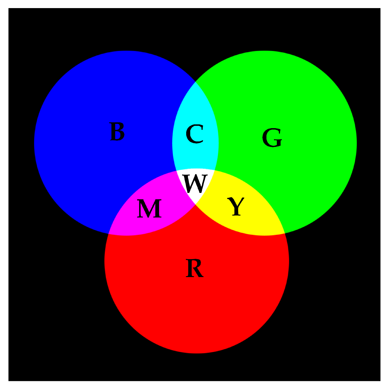
RGB color space is an additive color system, which is commonly used when presenting colors electronically. As shown in Figure 2, when mixing any two colors of red, green and blue, a brighter secondary color can be obtained, such as cyan, magenta and yellow. When mixing the same amount of red, green and blue, the white color should be obtained.
In RGB color space, red, green and blue colors are used as three basis colors. Any color in this space can be represented as linear combination of these three colors. Let X represents a given color in RGB space, then X can be expressed by
where R, G and B represents the red, green and blue colors, respectively. Thus, any color in a RGB color space can be represented as a vector . For convenience, we use boldface San-Serif font to denote some commonly used color vectors. The color vectors corresponding to red, green, blue, cyan, magenta, yellow, white and black are denoted as:
2.2.2. Color Stacking in RGB Space
In a typical VSS system, the decoder needs to stack shares in order to decode the secret bits. Such stacking is equivalent to logic OR operation if shares are assumed to be printed on transparencies. Let represents the logic OR operation between two bits a and d, then we have 0 ⊓ 0 → 0, 0 ⊓ 1 → 0, 1 ⊓ 1 → 1, 1 ⊓ 0 → 0. For any two colors from the eight colors , the stacking operation can also be represented as component-wise OR between color vectors. Let and be two colors in , then the stacking of and is
For example, the stacking of is
The stacking operation can be extended to more than two shares. Some examples of stacking of three shares are illustrated in Table 1.
2.3. Requirements for VSS-QR
The VSS-QR has a different setting as ordinary VSS because the decoders are different. For ordinary VC, the decoder consists of a stacking operation and a HVS. In contrast, for VSS-QR, the decoder consists of stacking operation and a QR code decoder.
Taking the -threshold scheme as an example, ordinary VC should satisfy two conditions. (1) Contrast condition: If all n shares are stacked, then the secret image should be revealed with sufficient contrast. (2) Security condition: If less than n shares are collected, no information about the secret bits should be revealed. For a VSS-QR scheme, in order to define the contrast condition and security condition, we must determine the computational ability of the attacker and define the meaning of “contrast” for a QR code decoder.
Security should be defined under an assumption of the ability of a potential attacker. This ability is quantified by the computational resources the attacker may have. In this paper, we assume that the attacker has a standard QR code decoder which may help him to reveal the embedded data in a QR code.
Contrast in VSS-QR is different from contrast in ordinary VSS. In ordinary VSS, one focuses on the difference between white region and black region. The larger the difference, the better the contrast. However, this contrast is defined for HVS, not for a QR code decoder. Using a QR code decoder as an observer, if the number of codeword errors is within ECC capability, then the “contrast” is acceptable for the QR code decoder. Otherwise, the “contrast” is not large enough for QR code decoder. So, here ’contrast’ is defined as correct decoding.
In summary, a VSS-QR should satisfy the following conditions.
- Contrast condition: If all n shares are collected and stacked, then the recovered secret QR code should be decoded correctly by a standard QR code decoder.
- Security condition: If k shares are collected, then the secret QR code should not be decoded by stacking any combination of these k shares.
3. The Proposed VSS-QR
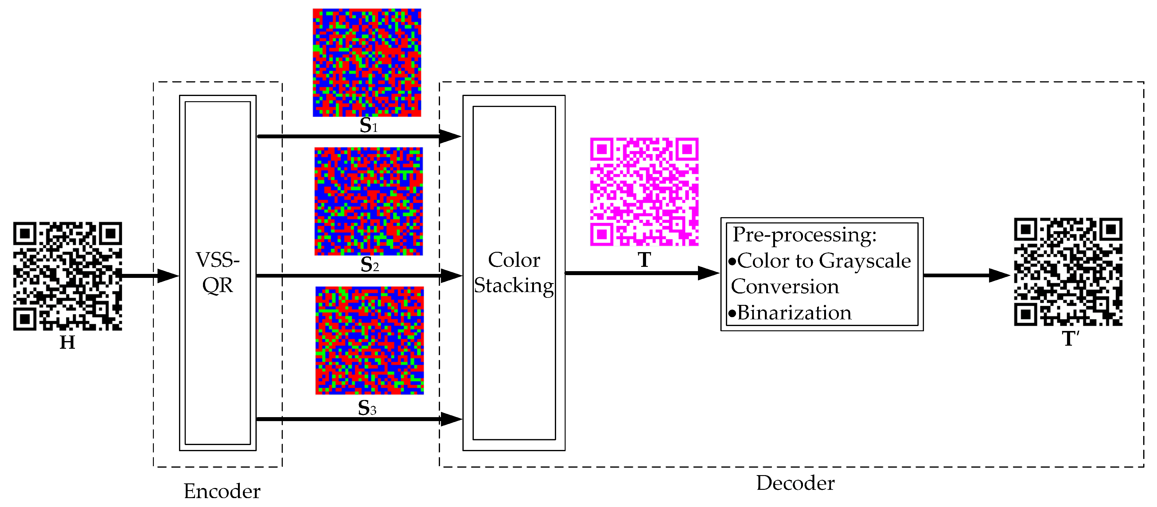
The overall block diagram of the proposed scheme is shown in Figure 3. It consists of an encoder and a decoder. The secret QR code is split into three shares by a VSS-QR algorithm. These three shares are transmitted to the receiver. At the receiving end, the receiver stacks all the three shares to generate a color QR code . Using a standard QR code decoder, the color QR code can be converted into a B/W QR code , which then can be decoded as an ordinary QR code. The encoder is described in Section 3.1 and the decoder is described in Section 3.2. The proposed algorithm is a -threshold VSS-QR, which can be extended to -threshold VSS-QR.
3.1. VSS-QR Encoder
Given a secret QR code , the encoder generates three shares . To ensure perfect reconstruction of at the decoder, we need to design the set of colors for encoding B/W secret modules. Let and be the two sets of colors for W/B secret modules, respectively. We intend to ensure that, a white secret module is constructed as white module and a black secret module is constructed as a module with a secondary color (such as cyan, magenta or yellow). To this end, we design and as follows. The set is designed as since all three primary colors are needed in order to generate a white module. To design , we need to determine the reconstructed color for black secret module. For example, if the black secret module should be reconstructed as magenta, then we set . In summary, let and be the secret module and reconstructed module at position , respectively. Then we set
if . If the color for the reconstructed module is not specified, then one may randomly select from the set . Once designed, the two sets and remain fixed during the encoding process.
For clarity, let us focus on only one module in the secret QR code and the reconstructed QR code . To share a black module , we must ensure that the two colors in appear at least once in the three shares . Let denotes random selecting an element from the set and assigning it to p, and let denotes the difference set between two sets and . Then we have
This operation can ensure that the stacking result of the three shares is a secondary color, i.e., .
To share a white module , we must ensure that the three colors in appear at least once in the three shares . We may use the following operations:
These operations can ensure that the stacking result of the three shares is white color, i.e., .
For example, if we select = and = , then for , we may get and . For , we may get and .
By applying the above encoding algorithm to each module of sequentially, we get three shares, each having modules, where D is the number of modules along each row/column of the secret QR code. For QR code with version V, D can be calculated as:
To render the shares as images, we must determine the size of each module. Let the size of each square module be a pixels, then each share image has pixels. For convenience, we use the same letter for QR code image with module indexing and QR code image with pixel indexing, where brackets are used for pixel indexing and parentheses are used for module indexing. For example, the QR code image is written as when accessing the module, but is written as when accessing the pixel, where and . The image rendering process can be expressed as:
for .
The above encoding algorithm is summarized in Algorithm 1.
| Algorithm 1 (3,3)-threshold VSS-QR algorithm |
| Input: Secret QR code Output: Three shares: .
|
3.2. VSS-QR Decoder
After receiving all the three shares, the decoder stacks them to get the reconstructed color QR code (Figure 3). Fortunately, this color QR code is directly recognizable by a standard QR code decoder. A QR code decoder first pre-process to generate a binary QR code , which includes color to grayscale conversion and binarization. Even though these pre-processing steps are assembled into a QR code decoder, we describe them here since they are essential for understanding the perfect reconstruction feature of VSS-QR.
3.2.1. Color Stacking
To reconstruct the secret QR code, the decoder stacks the three shares pixel by pixel:
for . One illustrating result is shown in Figure 3.
3.2.2. Color to Grayscale Conversion
The conversion from color to grayscale can be accomplished by a standard QR code decoder. However, the QR code standard does not specify how this conversion should be done. Different implementations are allowed. One possible solution is to convert the RGB space to HSI (Hue, Saturation and Intensity) color space, and then retain only the intensity component. Here we use “weighted average method” that assigns different weights to different color channels [31]. Using weighted average, the perceptually more important green channel are assigned with the largest weight. The weight vector is = [0.299, 0.587, 0.114]. So, the grayscale image can be calculated as:
for all , where .
3.2.3. Binarization
The grayscale QR code image needs to be binarized to facilitate QR code localization and module sampling in later steps. An advantage of QR code binarization is that we know in a priori that there are two classes of pixels in clean image, black pixels and white pixels. Thus the grayscale image should have two peaks in its histogram. With this knowledge, we may utilize Otsu’s algorithm to find the best threshold [32].
Let the histogram of the image be , where . Given a trail threshold , all pixels can be classified as either background pixels or foreground pixels. Let the mean for background, foreground and entire image be calculated as:
where and are the number of background pixels and number of foreground pixels, respectively. Let , then the intra-class variance can then be calculated as:
The optimal can be determined by maximizing this intra-class variance . Using , we obtain the binary QR code image as:
3.2.4. Decoding by Standard QR Code Scanner
After the above pre-processing steps, we get a B/W QR code image , which can be decoded by a standard decoder such as ZXing library [33].
3.3. Computational Complexity
The computational complexity of the proposed VSS-QR is proportional to the number of modules since the encoding is module-based. To be specific, the computational complexity is . In contrast, Fang’s algorithm is pixel-based, so the computational complexity is .
3.4. Timing Analysis
The basic processing unit of VSS-QR is a module, not pixel. The module is the component unit of QR code. The larger the version of the QR code, the more modules it has. Therefore, the size of the version is the main factor affecting the execution time of the algorithm. The execution time of the algorithm is gradually increased when the version is gradually increased.
4. Security Analysis
In this section, we show that the -threshold VSS-QR satisfies the security requirement as listed in Section 2.3. The QR code is assumed to be QR code 4-H, where the version of the QR code is 4 and the error correction level is H. This analysis can be extended to -threshold VSS-QR and other versions of QR code as well.
Since the encoding for black secret modules and white secret modules are different, so we define and as the sets of module positions corresponding to black modules and white modules, respectively, i.e.,
Next, we show that, after obtaining one or two shares, the attacker is unable to recover the secret QR code and hence is unable to read the embedded message. Without loss of generality, we assume that the encoder choose = and = as in Section 3.1.
4.1. Decoding from One Share
Given only one share, we show that the probability of codeword error is far beyond the ECC capability of QR code version 4-H.
The share image consists of color module, so a conversion from color module to B/W module is necessary. This problem is referred as module recovery and can be stated as follows. A secret QR code is encoded into three shares . Given only one share , where , determine a binary QR code to minimize the probability that . We define the module recovery error as
To minimize the probability of module recovery error , the optimal detector is a MAP (maximum a posteriori probability) detector under the condition of equal probability for [34].
To calculate the a posteriori probabilities, recall that = and = . So, given a blue module in , we have
To calculate other a posteriori probabilities, we need , where , and , where . For the secret QR code, it is usually assumed that , because the masking operation balances the number of B/W modules. For the share image , we can obtain:
The a posteriori probability then can be determined from the Bayes rule:
Similarly, we get , and , which are summarized in Table 2.
Based on the above a posteriori probabilities, the MAP module detector decodes
The probability of module recovery error can be calculated as:
Since each codeword consists of 8 modules, the probability of codeword error is
where denotes error of the t-th module in the codeword. For QR code (4-H), there are four blocks. For each block, the Reed-Solomon code is [23], where is the total number of codewords in a block, the number of data codewords, and is the ECC capability. The QR code is successfully decoded if the number of codeword errors is less than 8 in each block. So, the probability of correct decoding should be:
According to Equation (31), the attacker needs to try on approximately shares in order to get a correct decoding, which is almost impossible, by considering the fact that the total number of atoms in the universe is around .
In summary, given only one share, it is computational infeasible to decode the secret QR code correctly.
4.2. Decoding from Two Shares
Given any two shares, we show that the probability of codeword error is also far beyond the ECC of QR code (4-H). The following alalyis is similar to Section 4.1.
Let the two shares be: , where is different from . To recover the secret QR code, the decoder stacks the two shares module by module:
After this operation, . The blue modules are changed into cyan and yellow modules. Recall from = , = , Equations (6), (7), (8) and (9), (10), (11), given a cyan or yellow module in , we have:
Given a red or blue module, we have:
a posteriori
To calculate other a posteriori probabilities, we need , where , and , where . For the secret QR code, it is usually assumed that , because the masking operation balances the number of W/B modules. For the image , we can obtain:
The a posteriori probability then can be determined from the Bayes rule:
Similarly, we can get . The above results are summarized in Table 3.
Based on the above a posteriori probabilities, the MAP module detector decodes
The probability of module recovery error can be calculated as:
Since each codeword consists of 8 modules, the probability of codeword error is:
Similar to Equation (31), the probability of correct decoding should be:
This means that the attacker needs to try on shares to get a correct decoding, which is almost impossible for ordinary computers nowadays.
In summary, given any two shares, it is also computational infeasible to decode the secret QR code correctly.
5. Experiment
This section presents our experimental results, including a -threshold VSS-QR experiment, the actual machine time of our VSS-QR (Section 5.1), experiments with different colors (Section 5.2), experiments demonstrated in Section 4 (Section 5.3), and experiments of perfect module reconstruction (Section 5.4). For the actual machine time experiments (Section 5.1), we adopt QR code (“all versions”-H). All remaining experiments in this section adopt QR code (4-H). The conditions of computational experiment are shown in Table 4.
5.1. Experiment Results
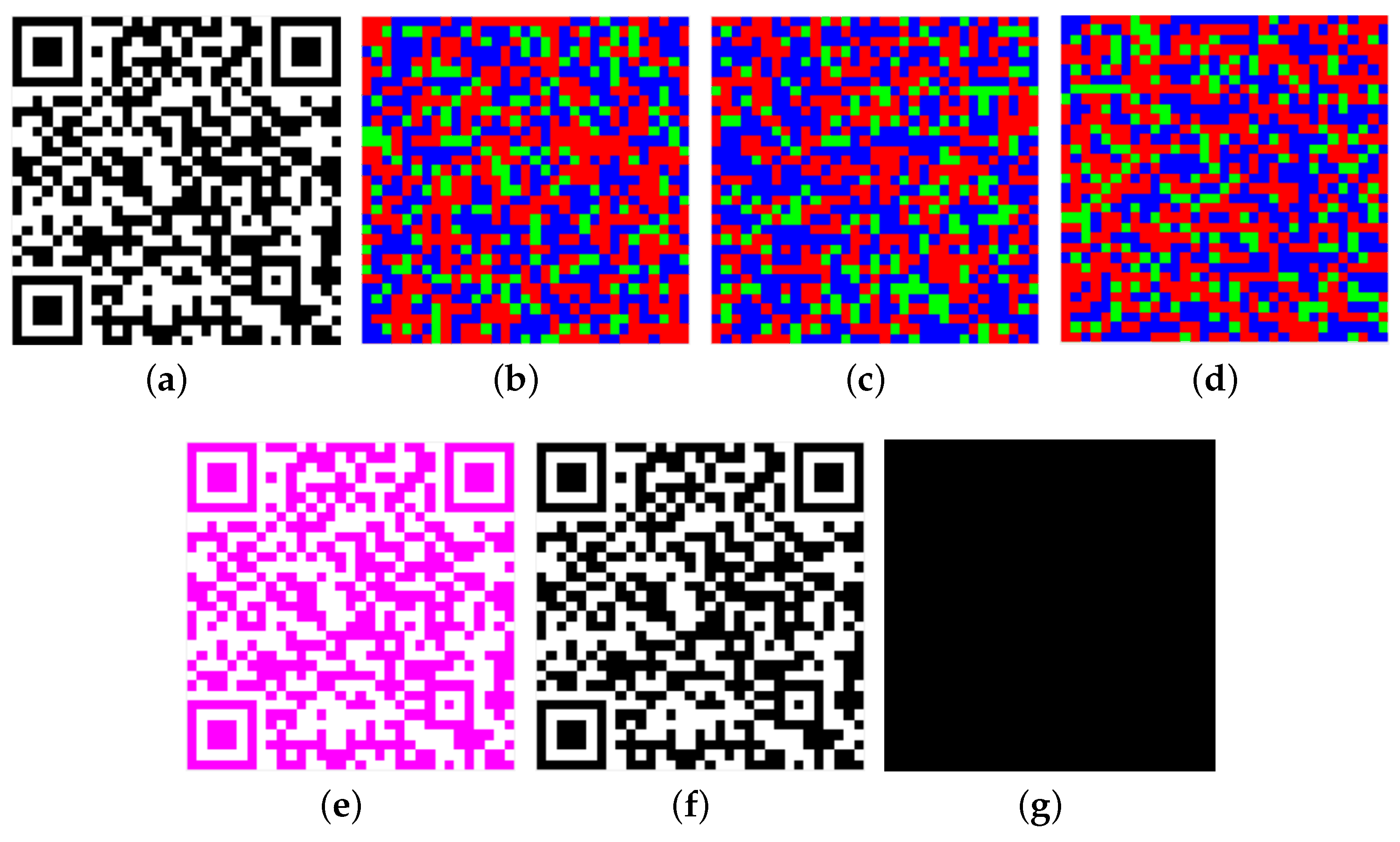
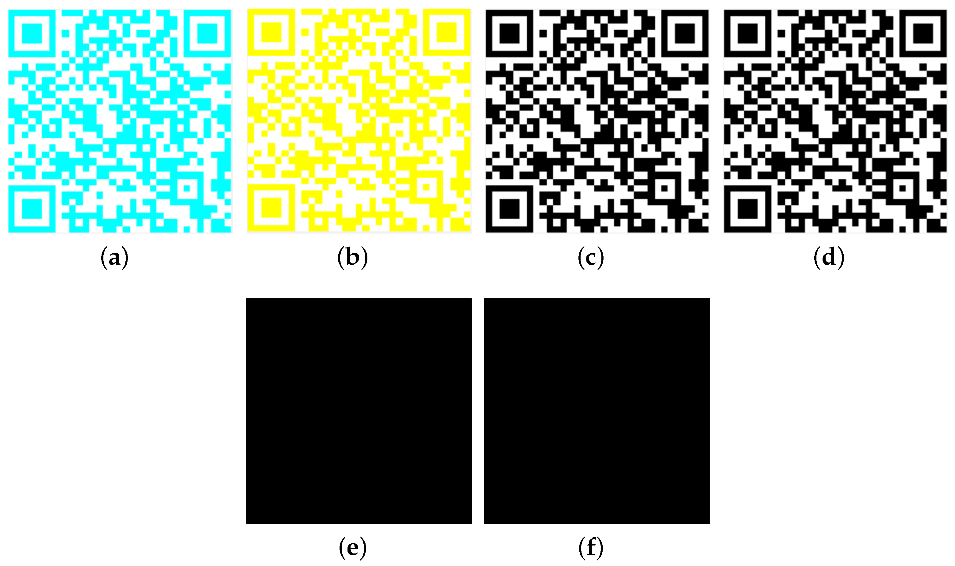
We assume that the encoder choose = and = as in Section 3.1. Secret QR code (Figure 4a) is divided into three meaningless images (Figure 4b–d). (Figure 4e) can be recovered once the three shares are stacked. This is not ordinary black and white QR code. It needs pre-processing to obtain black and white QR code (Figure 4f).
As shown in Figure 4g (White modules represent the difference between and .), VSS-QR can completely reconstruct the secret QR code .
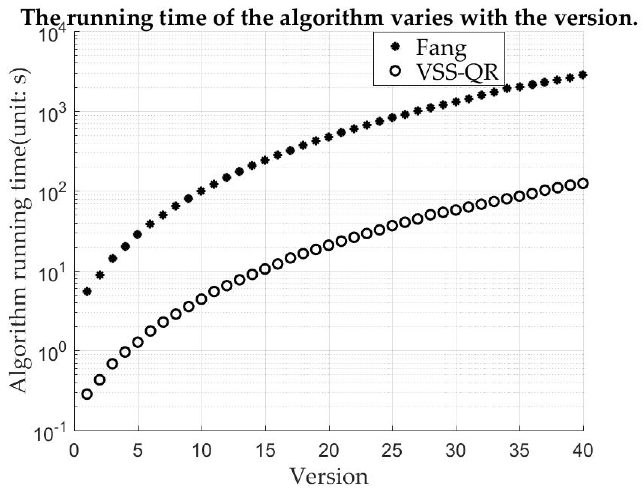
Section 3.3 gives the computational complexity VSS-QR algorithm and Fang’s algorithm. This can be verified by the actual machine time. The commonly used versions of QR code in our daily life are mostly 4 and 5. When a module size is pixels and the printing resolution 600 DPI (Dots Per Inch), the size of them printed is around 6 centimeters (cm), which is the width of a ordinary phone screen. Therefore, this size of the module is used in the experiment. As shown in Figure 5, the time difference between them is very small when the version is very small. As the version gradually increases, the time difference is obviously different. Fang’s algorithm is pixel-based and VSS-QR is module-based, so VSS-QR runs much faster when the version is larger. This result shows that the computational complexity of VSS-QR is significantly lower than Fang’s algorithm.
5.2. Other Colors
This section shows experiments for other choices of and , i.e., = , = , .
When = , the color of is cyan (Figure 6a). When = , the color of is yellow (Figure 6b). After pre-processing, they all become standard QR code (Figure 6c,d). As shown in Figure 6e,f (White modules represent the difference between them and .), these standard QR code are the same as . All secondary colors can be used for VSS-QR.
5.3. Experiments for Security
Section 4 shows that when only one share or two shares have been obtained, the reconstructed “secret QR code” will not be decoded correctly by the standard decoder. This section verifies this conclusion experimentally.
Experiments test one and two shares respectively. As shown in Table 5 and Table 6, the average of 10,000 experiments are recorded at a time. For QR code (4-H), there are four blocks. For each block, the Reed-Solomon code is [23], where is the total number of codewords in a block, the number of data codewords, and is the ECC. When the number of codeword errors per block exceeds 8, QR code will not be decoded by the standard decoder. From Table 5, we can see that the number of codeword errors in each block is about 24 (). So, the reconstructed “secret QR code” is not decoded correctly by only using a share. From Table 6, we can see that the number of codeword errors in each block is about 19 (). So, the reconstructed “secret QR code” is not decoded correctly by using any two shares. According to the experimental data, VSS-QR is secure.
5.4. Comparison with QRCSS
Similar to VSS-QR, QRCSS also divides the secret QR code into three shares. Every share is a standard QR code and six codewords are modified in each block. Because QR code has ECC capability, every share can be decoded correctly by standard QR code. In order to reconstruct secret QR code, three shares need to do “XOR”. The reconstructed QR code has some errors, but is lower than the ECC capability.
The experiments randomly added the same number of codeword errors to each block in and . Section 5.3 shows that the QR code (4-H) cannot be decoded by the standard decoder when the number of codeword errors per block exceeds 8. So, the number of codeword errors is from 1 to 9. When the number of codeword errors is 9, all of them cannot be decoded. Each experiment was performed 10,000 times. All results are shown in Table 7.
As the number of added-codeword-error increases, some cannot be decoded by the standard decoder. When this number exceeds 4, is difficult to decoded correctly by the standard decoder. Theoretically, when this number is less than 9, a few can be decoded. All cannot be decoded correctly when this number is greater than 4. However all that can be decoded by the standard decoder as this number increases. Until this number exceeds 8, cannot be decoded correctly. Compared with QRCSS, the biggest advantage of VSS-QR is that it can completely reconstruct the secret QR code, so VSS-QR preserves the ECC capability of QR code.
5.5. Summary of Experiments
As shown in Table 8, VSS-QR has two advantages. Comparing with [24], the run time of VSS-QR is faster than that of it. Comparing with [26], VSS-QR does not sacrifice ECC capability of QR code. VSS-QR inherits the merits of both of them.
VSS-QR is module-based, so the main factor affecting the running speed of it is the version of QR code. The larger the version, the slower it will run.
6. Extension to -threshold VSS-QR
The proposed -threshold VSS-QR can be extended to -threshold VSS-QR. This section presents a design of -threshold VSS-QR.
To design -threshold VSS-QR, the value of n and k need to be determined. The range of n is , where is the number of black modules and is the number of white modules in . In order to determine k, we need determine the following four parameters:
- l: the number of modules that can be modified in every share.
- : the ECC capability of QR code in every block.
- : the number of block in QR code.
- from Equation (49).
The number of changeable modules l can be calculated as
Assuming that 8 modules in a codeword are all wrong, we can determine as
When , the reconstructed QR code may be decoded by using k shares. However, this QR code has some errors. If we want to completely reconstruct the secret QR code, all shares must be obtained.
Encoding algorithm for and are the same as proposed in Section 3.1. Therefore, and must be obtained when decoding. In the following shares, encoding rule is changed. Only l modules are modified in next every share. The encoding algorithm is shown in Algorithm 2. Decoding method is the same as proposed in Section 3.2.
| Algorithm 2-threshold VSS-QR algorithm |
| Input: Secret QR code Output: n shares: .
|
7. Conclusions
In this paper, we propose a color visual secret sharing for QR Code with perfect module reconstruction. The new VSS-QR is module-based, which overcomes the low encoding speed disadvantage of pixel-based algorithm. It also ensures that the secret QR code can be completely reconstructed. The experiment results show that it is secure under the condition that the computational device available to the attacker is limited to standard QR code decoder.
The security of VSS-QR does not belong to perfect security but belongs to the computational security. It is secure under the assumption that the attacker’s tool is limited to QR code decoder. The method we proposed is to use multiple colors that can also be extended. In our future work, a method will be designed to improve the security of QR code, and VSS will utilize multiple tones instead of multiple colors.
Author Contributions
Conceptualization, T.L. and B.Y.; software, T.L., B.Y.; Formal analysis, T.L., B.Y. and J.-S.P.; Methodology, T.L., B.Y. and J.-S.P.; Writing—original draft, T.L. and B.Y.; Writing—review & editing, T.L., B.Y. and J.-S.P.
Funding
This research was funded by NATURAL SCIENCE FOUNDATION OF CHINA 61571139 and 61272432, SHANDONG PROVINCIAL NATURAL SCIENCE FOUNDATION ZR2014JL044.
Conflicts of Interest
The authors declare no conflict of interest.
References
- Chen, C.M.; Xiang, B.; Liu, Y.; Wang, K.H. A secure authentication protocol for Internet of vehicles. IEEE Access 2019, 7, 12047–12057. [Google Scholar] [CrossRef]
- Chen, C.M.; Wang, K.H.; Yeh, K.H.; Xiang, B.; Wu, T.Y. Attacks and solutions on a three-party password-based authenticated key exchange protocol for wireless communications. J. Ambient. Intell. Humaniz. Comput. 2019, 10, 3133–3142. [Google Scholar] [CrossRef]
- Pan, J.S.; Kong, L.; Sung, T.W.; Tsai, P.W.; Snášel, V. α-Fraction first strategy for hierarchical model in wireless sensor networks. J. Internet Technol. 2018, 19, 1717–1726. [Google Scholar]
- Wu, T.Y.; Chen, C.M.; Wang, K.H.; Meng, C.; Wang, E.K. A provably secure certificateless public key encryption with keyword search. J. Chin. Inst. Eng. 2019, 42, 20–28. [Google Scholar] [CrossRef]
- Pan, J.S.; Lee, C.Y.; Sghaier, A.; Zeghid, M.; Xie, J. Novel Systolization of Subquadratic Space Complexity Multipliers Based on Toeplitz Matrix-Vector Product Approach. IEEE Trans. Very Large Scale Integr. (VLSI) Syst. 2019, 27, 1614–1622. [Google Scholar] [CrossRef]
- Lin, P.Y.; Chen, Y.H. High payload secret hiding technology for QR codes. EURASIP J. Image Video Process. 2017, 2017, 14. [Google Scholar] [CrossRef] [Green Version]
- Huang, P.C.; Chang, C.C.; Li, Y.H.; Liu, Y. High-payload secret hiding mechanism for QR codes. Multimed. Tools Appl. 2019, 78, 22331–22350. [Google Scholar] [CrossRef]
- Huang, H.C.; Chang, F.C.; Fang, W.C. Reversible data hiding with histogram-based difference expansion for QR code applications. IEEE Trans. Consum. Electron. 2011, 57, 779–787. [Google Scholar] [CrossRef]
- Thodi, D.M.; Rodriguez, J.J. Expansion Embedding Techniques for Reversible Watermarking. IEEE Trans. Image Process. 2007, 16, 721–730. [Google Scholar] [CrossRef]
- Shi, Y.; Li, X.; Zhang, X.; Wu, H.; Ma, B. Reversible data hiding: Advances in the past two decades. IEEE Access 2016, 4, 3210–3237. [Google Scholar] [CrossRef]
- Weng, S.; Pan, J.S. Reversible watermarking based on two embedding Schemes. Multimed. Tools Appl. 2016, 75, 7129–7157. [Google Scholar] [CrossRef]
- Weng, S.; Zhang, G.; Pan, J.S.; Zhou, Z. Optimal PPVO-based reversible data hiding. J. Vis. Commun. Image Represent. 2017, 48, 317–328. [Google Scholar] [CrossRef]
- Weng, S.; Pan, J.S.; Zhou, L. Reversible data hiding based on the local smoothness estimator and optional embedding strategy in four prediction modes. Multimed. Tools Appl. 2017, 76, 13173–13195. [Google Scholar] [CrossRef]
- Hong, W.; Zhou, X.; Weng, S. Joint adaptive coding and reversible data hiding for AMBTC compressed images. Symmetry 2018, 10, 254. [Google Scholar] [CrossRef]
- Weng, S.; Chen, Y.; Ou, B.; Chang, C.C.; Zhang, C. Improved K-Pass Pixel Value Ordering Based Data Hiding. IEEE Access 2019, 7, 34570–34582. [Google Scholar] [CrossRef]
- Weng, S.; Zhao, Y.; Pan, J.S.; Ni, R. A novel reversible watermarking based on an integer transform. In Proceedings of the 2007 IEEE International Conference on Image Processing, San Antonio, TX, USA, 16 September–19 October 2007; Volume 3, pp. 241–244. [Google Scholar]
- Naor, M.; Shamir, A. Visual Cryptography; Springer: Boston, MA, USA, 1994; pp. 1–12. ISBN 978-3-540-60176-0. [Google Scholar]
- Hou, Y.C. Visual cryptography for color images. Pattern Recognit. 2003, 36, 1619–1629. [Google Scholar] [CrossRef]
- Fang, W.P.; Lin, J.C. Visual cryptography with extra ability of hiding confidential data. J. Electron. Imaging 2006, 15, 023020. [Google Scholar] [CrossRef]
- Lin, S.J.; Lin, J.C.; Fang, W.P. Visual Cryptography (VC) with non-expanded shadow images: Hilbert-curve approach. In Proceedings of the 2008 IEEE International Conference on Intelligence and Security Informatics, Taipei, Taiwan, 17 June 2008; pp. 271–272. [Google Scholar]
- Fang, W.P. Friendly progressive visual secret sharing. Pattern Recognit. 2008, 41, 1410–1414. [Google Scholar] [CrossRef]
- Suklabaidya, A.; Sahoo, G. Visual cryptographic applications. Int. J. Comput. Sci. Eng. 2013, 5, 464. [Google Scholar]
- ISO, B. IEC 16022: Information Technology-Automatic Identification and Data Capture Techniques-Data Matrix Bar Code Symbology Specification. BS ISO/IEC 2006, 16022. [Google Scholar]
- Fang, W.P. Offline QR code authorization based on visual cryptography. In Proceedings of the 2011 Seventh International Conference on Intelligent Information Hiding and Multimedia Signal Processing, Dalian, China, 14–16 October 2011; pp. 89–92. [Google Scholar]
- Lin, P.Y. Distributed secret sharing approach with cheater prevention based on QR code. IEEE Trans. Ind. Inform. 2016, 12, 384–392. [Google Scholar] [CrossRef]
- Chow, Y.W.; Susilo, W.; Yang, G.; Phillips, J.G.; Pranata, I.; Barmawi, A.M. Exploiting the error correction mechanism in QR codes for secret sharing. In Australasian Conference on Information Security and Privacy; Springer: Cham, Switzerland, 2016; pp. 409–425. [Google Scholar]
- Cheng, Y.; Fu, Z.; Yu, B. Improved Visual Secret Sharing Scheme for QR Code Applications. IEEE Trans. Inf. Forensics Secur. 2018, 13, 2393–2403. [Google Scholar] [CrossRef]
- Shyu, S.J. Image Encryption by Random Grids. Pattern Recognit. 2007, 40, 1014–1031. [Google Scholar] [CrossRef]
- Gonzalez, R.C.; Wintz, P. Digital Image Processing; Addison-Wesley Publishing Co., Inc. Applied Mathematics and Computation: Reading, MA, USA, 1977; pp. 290–294. [Google Scholar]
- Cimato, S.; Yang, C.N. Visual Cryptography and Secret Image Sharing; CRC Press: Boca Raton, FL, USA, 2017; pp. 38–39. [Google Scholar]
- Burger, W.; Burge, M.J. Principles of Digital Image Processing: Fundamental Techniques; Springer: Boston, MA, USA, 2010; pp. 200–204. ISBN 978-1-84800-190-9. [Google Scholar]
- Otsu, N. A threshold selection method from gray-level histograms. IEEE Trans. Syst. Man Cybern. 1979, 9, 62–66. [Google Scholar] [CrossRef]
- Zxing Library. 2019. Available online: https://github.com/zxing/zxing (accessed on 30 September 2015).
- Kay, S. Fundamentals of Statistical Signal Processing: Detection Theory; Prentice Hall: Upper Saddle River, NJ, USA, 1998. [Google Scholar]
Figure 1.
Structure of a typical QR code (Version 7).

Figure 2.
Color mixing in RGB additive color space.

Figure 3.
The overall block diagram.

Figure 4.
(a): ; (b): ; (c): ; (d): ; (e): ; (f): ; (g): The difference images between and .

Figure 5.
The running time of the algorithm varies with version.

Figure 6.
(a): ; (b): ; (c): ; (d): ; (e): The difference image between and ; (f): The difference image between and .
Figure 6.
(a): ; (b): ; (c): ; (d): ; (e): The difference image between and ; (f): The difference image between and .


Table 1.
Color stacking of three shares.
| Color 1 () | Color 2 () | Color 3 () | (⊓⊓) |
|---|---|---|---|
Table 2.
Color probability diagram of a share.
| Color(c) | |||
|---|---|---|---|
 | |||
 | 0 | 1 | |
 |
Table 3.
Color probability diagram of two shares.
| Color(c) | |||
|---|---|---|---|
 | 1 | 0 | |
 | 1 | 0 | |
 | 0 | 1 | |
 | |||
 | 0 | 1 |
Table 4.
The conditions of a computational experiment.
| Hardware | Development Environment |
|---|---|
| CPU: Intel(R) Core(TM): i5-8500@ 3.00GHZ Memory: 8 G | MATLAB R2016b |
Table 5.
The result of experiment about reconstruct “secret QR code” by using one share.
| 1 | 24.291 | 24.4871 | 24.2361 | 24.5258 |
| 2 | 24.2984 | 24.4949 | 24.2484 | 24.5226 |
| 3 | 24.2856 | 24.4965 | 24.2371 | 24.5253 |
| 4 | 24.3002 | 24.4888 | 24.2372 | 24.5141 |
| 5 | 24.297 | 24.486 | 24.2269 | 24.5322 |
| 6 | 24.3092 | 24.4925 | 24.2502 | 24.5278 |
| 7 | 24.2879 | 24.4938 | 24.2259 | 24.5231 |
| 8 | 24.3024 | 24.4942 | 24.2352 | 24.5273 |
| 9 | 24.2877 | 24.4962 | 24.2464 | 24.5285 |
| 10 | 24.2905 | 24.5031 | 24.2419 | 24.5299 |
denotes the number of codeword errors in the -th block, for .
Table 6.
The result of experiment about reconstruct “secret QR code” by using any two shares.
| 1 | 19.0803 | 19.9352 | 19.4074 | 19.9332 |
| 2 | 19.048 | 19.9127 | 19.4067 | 19.9441 |
| 3 | 19.0621 | 19.9514 | 19.4229 | 19.9422 |
| 4 | 19.0651 | 19.9321 | 19.3731 | 19.9392 |
| 5 | 19.0079 | 19.9016 | 19.3957 | 19.9312 |
| 6 | 19.0141 | 19.9323 | 19.4219 | 19.9458 |
| 7 | 19.0258 | 19.9303 | 19.3769 | 19.903 |
| 8 | 19.0909 | 19.9517 | 19.4297 | 19.9377 |
| 9 | 19.0548 | 19.9258 | 19.3743 | 19.9386 |
| 10 | 19.0421 | 19.9196 | 19.4264 | 19.9417 |
denotes the number of codeword errors in the -th block, for .
Table 7.
ECC Test Experiment.
| 10000 | 4975 | 1084 | 273 | 128 | 0 | 0 | 0 | 0 | |
| 10000 | 10000 | 10000 | 10000 | 10000 | 10000 | 10000 | 10000 | 0 |
denotes the number of QR code that can be decoded by standard decoder when z codewords are changed randomly in each block.
© 2019 by the authors. Licensee MDPI, Basel, Switzerland. This article is an open access article distributed under the terms and conditions of the Creative Commons Attribution (CC BY) license (http://creativecommons.org/licenses/by/4.0/).
Share and Cite
MDPI and ACS Style
Liu, T.; Yan, B.; Pan, J.-S. Color Visual Secret Sharing for QR Code with Perfect Module Reconstruction. Appl. Sci. 2019, 9, 4670. https://0-doi-org.brum.beds.ac.uk/10.3390/app9214670
AMA Style
Liu T, Yan B, Pan J-S. Color Visual Secret Sharing for QR Code with Perfect Module Reconstruction. Applied Sciences. 2019; 9(21):4670. https://0-doi-org.brum.beds.ac.uk/10.3390/app9214670
Chicago/Turabian StyleLiu, Tao, Bin Yan, and Jeng-Shyang Pan. 2019. "Color Visual Secret Sharing for QR Code with Perfect Module Reconstruction" Applied Sciences 9, no. 21: 4670. https://0-doi-org.brum.beds.ac.uk/10.3390/app9214670
Note that from the first issue of 2016, this journal uses article numbers instead of page numbers. See further details here.