1. Introduction
Technological developments in the last decades have considerably enhanced the precision and time efficiency of a lot of medical procedures, with many specialized tools emerging to support critical treatments and the diagnosing of complex diseases. In the area of dentistry, electric tools and computer-assisted optimization, approaches have also been largely adopted [
1], including computer vision techniques [
2], significantly supporting the execution of important procedures. Particularly, the area of endodontics is a subarea of dentistry that is concerned with root canal treatments and the associated dental pulp and its surrounding tissue, which has required the use of very specialized tools to facilitate the accomplishment of complex tasks [
3]. This scenario has favored the development of different endodontic motors and assistive technologies, with important results in this area.
Modern endodontic procedures are expected to be executed with the support of an electric motor and an endodontic file attached to it, with different types of files being available to be used in such procedures. Actually, nickel–titanium (NiTi) endodontic files have been widely used for root canal preparation in endodontic treatments; however, despite their clear advantages, the rotary motion of the employed motors still presents a considerable risk of endodontic file fractures, mainly during its use in curved canals [
4,
5,
6]. In 2008, a new kinematic for the use of NiTi instruments in an asymmetric oscillatory movement—the so-called reciprocating movement, which was proposed as a potential alternative to the conventional continuous rotation pattern [
7], aiming to facilitate the root canal shaping procedure while reducing the instrument fatigue [
8,
9]. With movements alternately happening in both directions, in a well-defined forward/backward movement cycle, the performance of the intended endodontic procedures could be significantly improved, while enlarging the average lifetime of the employed files.
Originally, reciprocating movement was described with
clockwise (CW) and
counter-clockwise (CCW) rotation angles at a rotational speed of 400 RPM (rotations per minutes), driven by an electric motor [
7]; however, new configurations were later defined. Based on the same reciprocating movement concept, two commercial systems were launched in the market: the Reciproc and the WaveOne [
10]. Both systems were developed to be used in their specific reciprocating modes, which were RECIPROC ALL (
CCW and
CW at 300 RPM) and WAVEONE ALL (
CCW and
CW at 350 RPM), driven by a specific contra-angle handpiece attached to an electric motor, such as the Reciproc Silver (VDW) or the X-Smart Plus (Dentsply Sirona).
Due to the largely recognized benefits of the reciprocating movement over continuous rotation [
5,
8,
11], the open motor concept was fostered to allow the production of different motors by any manufacturer, clearly indicating the ever-increasing popularity of reciprocating movement for endodontic procedures. In this sense, such motors could be configured to operate following different movements patterns by setting clockwise and counter-clockwise angles, torque and speed, since the overall reciprocating movement principle was preserved; however, these configuration parameters have not been clearly disclosed by their manufacturers and there is no evidence that the indicated set up is a reliable choice, because actual kinematic parameters can be different than the assumed operation values.
Considering that instrument kinematics have a direct impact on cyclic fatigue resistance of NiTi instruments and root canal shaping outcomes [
12,
13,
14], the precision and accuracy of the reciprocating kinematics may be of clinical importance. For that, some mechanisms should be employed to evaluate the movement patterns of the instruments, allowing the assessment of the performed movements according to the information provided by the suppliers. In fact, since a particular file may be fabricated to operate under a certain expected reciprocating movement pattern and speed, knowing the actual operation characteristics of a motor may be relevant when deciding which files to use. Additionally, due to the risk that broken files may have to endodontic procedures, avoiding undesired file fatigue resulted from the adoption of inadequate reciprocating motors is an expected benefit of the proposed assessment approach.
Broadly speaking, the movement nature of reciprocating motors makes them hard to be evaluated by the naked eye. In this sense, computer-assisted methods to evaluate “quality” parameters, such as movement angles and RPM, could be exploited to allow the desired assessment with a certain level of precision. Among the possibilities for that, image processing presents itself as an affordable and effective approach to provide an account of the movement of the motors over time. This article then proposes a novel computer-vision-based methodology to assess the precision of reciprocating angles in endodontic motors, as well as their rotation speeds, by the processing of consecutive images that contain a reference point drawn on a rotating disc. All coordinates of the points extracted from the images are considered on a geometry-based method proposed in this work.
Therefore, tackling this problem adopting a multi-disciplinary approach, the contributions of this article are defined as follows: (a) the specification of a geometry-based method to keep track of the directions of movement and the traveled angular distances; (b) the definition of a hardware configuration and ideal assembling to allow the capturing of images; (c) an OpenCV/Python implementation of the proposed method, with different modules to display the results; (d) the assessment of a group of three popular endodontic reciprocating motors.
The remainder of this article is organized as follows.
Section 2 presents some related works in the area of image processing when evaluating health procedures and computer-assisted dentistry tools. The proposed method is described in
Section 3.
Section 4 presents implementation and evaluation issues, as well as the achieved numerical results. Discussions are presented in
Section 5. Finally, conclusions and references are presented.
2. Related Works
For many scenarios, images can provide valuable information about any particular scene. Within a group of images, one or more objects (targets) can be identified on the images by some algorithm, with practical applications in many areas such as remote sensing [
15], medical diagnosis [
16] and face recognition in public security systems [
17]. In fact, when properly performed, the processing of images can be automatized in a way that a large group of them can be processed to extract some relevant information that could be hardly achieved otherwise. With the development of image processing algorithms and the availability of open-source libraries for imaging and computer vision tasks, useful approaches have emerged for different detection objectives [
18].
Overall, the adoption of computer-assisted solutions to support in dentistry and other medical areas is not a novelty, with many approaches being described in recent years comprising different strategies [
2,
19,
20,
21,
22,
23]. With new advances in sensory technologies and image processing algorithms, the available computational resources have increased considerably in the last years, but image processing techniques have been usually favored due to their lower implementation and computational costs in many scenarios [
24,
25].
Although image processing has been largely adopted to support identifying diseases and providing helpful data for medical treatments [
2], the quality assessment of biomedical tools has not been properly discussed in the literature, usually due to the fact that the configurations and settings of the manufacturers are expected to be fully trusted by the users. Moreover, it can be said that different biomedical tools will have particular operational characteristics that will prevent the development of generic methods that are useful for different tools in multiple contexts; however, with the adoption of image processing and computer vision algorithms, effective methods could be derived to support the assessment of many biomedical tools, particularly in a very instrument-heavy area such as dentistry [
26].
When concerning the movement patterns of reciprocating endodontic motors, previous studies have tried to evaluate the actual kinematics of endodontic motors using high-speed camera analysis [
27,
28], which seems to be a promising approach considering the particularities of the assessed movements. In those works, image processing was adopted to identify actual movement considering a visual reference (target); however, the works in [
27,
28] were centered on human-assisted identification of the kinematic phases considering manual analysis of each image captured by a high-speed camera. In fact, such type of manual analysis may be prone to errors and present low efficiency, specially when comparing different motors, which has fostered the development of automatized methods.
In this scenario of high efficiency and low cost of image processing algorithms, especially considering the availability of public algorithms using well-known image processing filters, the kinematics of endodontic reciprocating motors can be computed in a fully automated way, bringing an important contribution to this research area. For that, we leverage existing visual computing algorithms designed for objects detection in consecutive images, and use this to create a database that tracks the actual movements of endodontic reciprocating motors. Then, a new geometry-based method is derived to compute the effectively covered angular distances over time. In doing so, we believe that a highly effective and affordable method is created, with a reasonable level of precision, bringing an important contribution not presented by previous works.
3. Materials and Methods
As discussed before, reciprocating motors may be developed following different physical projects and operational goals, which may have diverse impacts on endodontic procedures. Moreover, such motors may also operate in a different way than the specifications provided by the manufacturers, also raising concerns about the precision of such tools. In both cases, since they rotate faster than the naked eye can properly identify the performed movements, there should be some automated method to account the movements of the motors as they operate, providing enough information for the performance assessment of different motors available on the market. A proposed method is described in this section.
There are multiple ways to measure the speed and rotation directions of rotating objects; however, the performance, associated costs and deployment complexities of the employed solution may vary considerably. In this scenario of possibilities, the use of image processing algorithms may affordably process a large set of images comprising some previously defined visual patterns, guiding the detection of speeds, angles variations and movement directions of rotating objects that have a certain uniform behavior. For the scenario of reciprocating endodontic motors, the way they operate makes them good candidates for the adoption of image processing algorithms.
3.1. Modeling the Assessment Environment
The proposed approach is based on the processing of multiple consecutive images. For a set s of images, for identifying the corresponding set of images within a broader group of S sets, there will be a total of images taken for a particular assessment task. In this set of images, each image , for , will be created following a sequential sampling process, with an image being taken just after image under the same configured sampling frequency (a new image every seconds). Such sequential sampling assures a temporal dependence for the images, leading us to process them in the exact same sequence from which they were created.
In order to allow the proper processing of the rotation patterns of the motors, an acrylic resin disc was created to be attached onto a contra-angle tool, aligning the center of the disc to the position where endodontic files are inserted. Additionally, a small red dot was drawn closer to the border of the disc, on its visible part, acting as an optical target to be processed by the developed image processing algorithm. In doing so, since the contra-angle will be fixed during all image captures, any optical target on any image will be viewed with the same perspective from the reference x-axis, which allows us to compute the angular variation of two different spots on consecutive images, and, consequently, the direction and amount of rotation of the motors.
In
Figure 1, the general schema for the created plastic disc to be attached on a contra-angle is presented.
The created and assembled disc is expected to be viewed by a high-speed video camera positioned on a fixed distance, with its lens on a parallel plane from the disc, entirely viewing it. Since different sets of images may be created, the configuration of the camera in any given moment is allowed to change, once it remains valid for all images in the same set. Actually, since the proposed algorithm is designed to be highly configurable, changes in the operation of the camera do not affect the attainable results, as discussed in the next subsection.
3.2. Processing the Images
When taking images in the defined scenario, every captured image is saved as a single file into the currently defined directory, being identified with any name pattern. Then, the employed camera operates with a frequency when creating a set s of images, resulting in each image being taken every second and saved to be further processed.
After all images are saved, the algorithm moves to the second phase. The directory containing all images of set s is read, with each image being processed sequentially according to their creation timestamp. In this phase, the processing of the images is performed as follows:
For each image , the disc is identified, resulting in the cropping of the image in order to comprise only this visual part, reducing the computational cost when compared to the processing of entire images. In this phase, the center of the cropped image is saved, , which is the center of the disc (valid for all detected spots in the considered images set);
The cropped image is transformed into a grayscale image, facilitating the detection of (any) spots. In the sequence, the image contrast is increased (we assume a standard factor of 50%). Although different image processing techniques could be employed, we consider a Gaussian low-pass filter as reference to reduce the high-frequency components of the grayscale image, since it has a reasonable performance with low computational cost. Then, one or more spots can be identified through a threshold-based technique settled to small objects. In fact, since the center of the disc is a regular screw, imperfections can be wrongly detected as a visual target. In order to overcome this, spots detected very close to the center of the disc are ignored, as well as “imperfections” processed as black spots outside the disc (the disc’s radius is used to compute the maximum allowed distance);
Every processed image will result in the computation of the (x,y) coordinates of the center of the detected spot. Then, this information, along with the name of the processed image and the disc’s center, is inserted into a text file. At the end of the processing of the set s, a result file will contain all coordinates of the (correctly) detected spots in each processed image.
When all images are processed, the algorithm moves to the third phase, described in the next subsection.
3.3. Computing the Movement Parameters
Having the spot’s coordinates of each image, the rotation speed and movement directions can be computed using geometry. So, in this last phase of the algorithm, different important information is achieved, supporting the desired assessment of the evaluated motors.
In the first place, every spot is associated with an angular distance in relation to the center of the disc. The angular distance
is defined as expressed in Equation (
1). The value of
will be within the range from
to
, which means that it will be in one of four possible quadrants (I, II, III or IV), as specified in
Figure 1 (the values of the angles increase in a counter-clockwise fashion).
With the value of
and
, for
, the angular distance
can be computed as presented in Equation (
2). When the disc is rotating,
may assume any value, even suddenly changing from a small angle value (Quadrant I) to a high angle value (Quadrant IV). Since the motor can move in both clockwise and counter-clockwise directions, the correct computation of the angular distance between two points have to be performed considering a quadrant test,
: for clockwise movement, if
(which means that
is in Quadrant I) or
, while
or
, the angular distance computation needs a compensation by 360
, and the opposite is valid for counter-clockwise movement, as expressed in Equation (
2).
After being able to compute the angular distance between any two spots, different movement parameters can be computed. Initially, considering previous works in this area [
13,
14,
27], it is desired to compute the greatest angular movement of the motors, defined as the engaging angle (
), which is the greatest value of
in a forward/backward cycle. Additionally, we also want to compute the disengaging angle (
), which is the greatest value of
in the opposite direction of the same movement cycle.
Besides the values of
and
, it is also desired to compute the RPM of the assessed motors, allowing comparisons with the specifications provided by the manufacturers. For that, we take the number of images that comprises the cumulative sum of the angular movements of the motors until it reaches
, associating it with the defined value of
. For
images being processed to indicate a
cumulative angular movement, Equation (
3) stands for the computation of the RPM (for time in seconds).
4. Results
4.1. Implementation Issues
The proposed mathematical model and geometrical computation of the angles can be implemented in different ways, since some considerations are properly taken during the implementation process. In short, when implementing the proposed method, the following remarks apply:
Image processing: there are some available programming libraries to handle images and perform a group of basic processing functions on them. When choosing such a library, it should be considered if popular functions such as the ones based on Gaussian filters and threshold-based objects detection are available;
Programming functions: any modern programming language can be adopted to implement the proposed method. Actually, the expected services for the implemented algorithms, such as the processing of text files and geometry computations, are available in all modern programming languages;
Visual evaluation of the movement patterns: although it is not a fundamental service to be provided, we believe that a visual module to track the movement of the motors as an animated presentation, with very low speed between consecutive movement states, can be valuable when perceiving the kinematics of the motors in a broader perspective.
Based on the expected services when implementing the proposed method, we adopted the OpenCV programming library (opencv-python 4.1 version) and the Python 3 language in a unified script, which was responsible to process each image individually, extracting information about the red dot on the disc and its center, and saving such information into a text file. Actually, the use of OpenCV/Python for image processing has been a common approach when processing images [
29,
30], with reasonable efficiency for a lot of different image processing tasks. Additionally, Python is a popular programming language with extensive open source resources and community support.
For the implemented Python script, all images in a directory are processed, one by one, considering a sorting pre-processing algorithm that considers the timestamp of the image files (images are processed in the same order that they were created). The script was implemented to process JPEG or PNG images taken by a camera, but other formats could be considered in future implementations. As an example of input file,
Figure 2 presents one of the taken images.
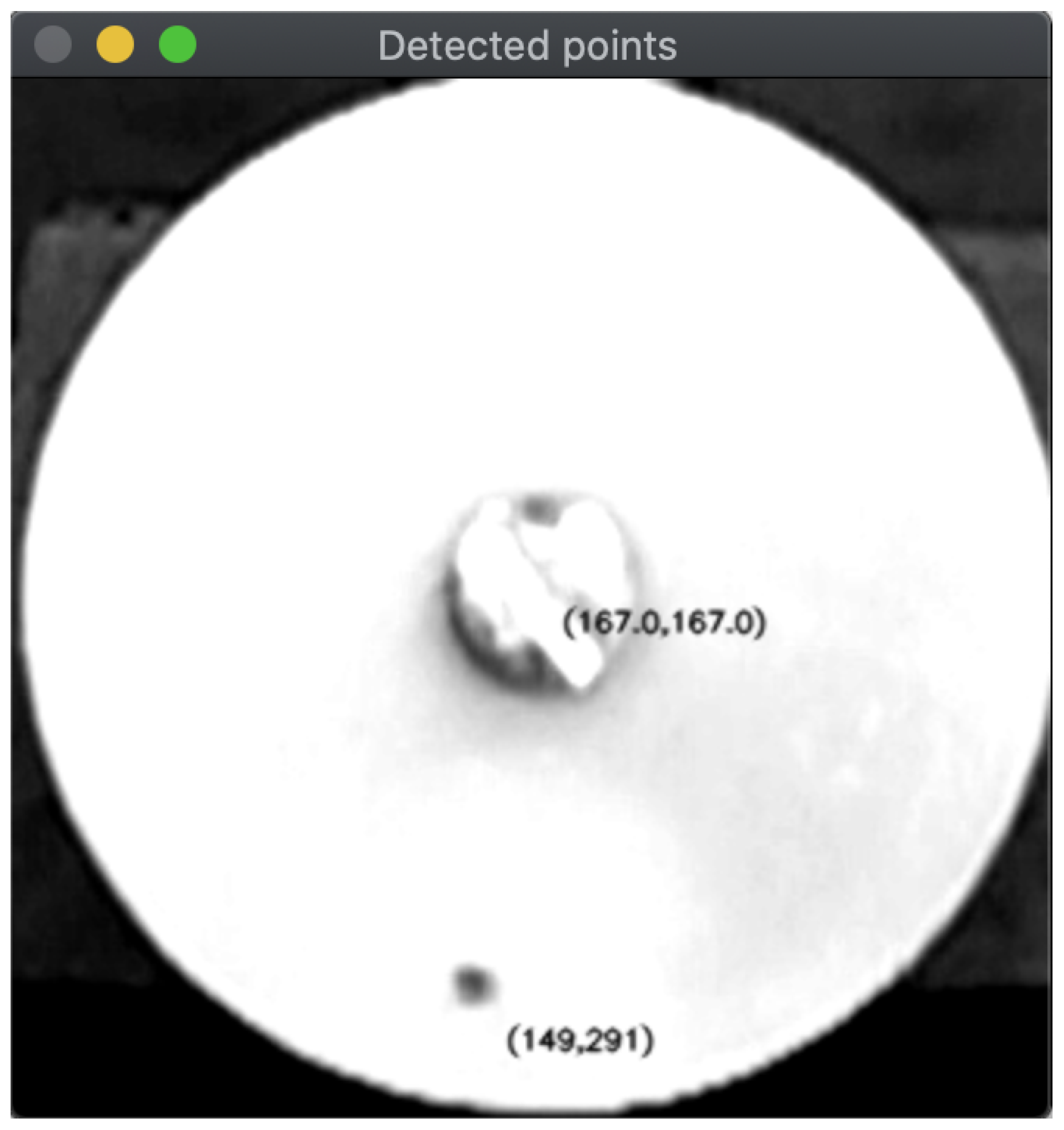
As previously defined, each image is transformed into a grayscale image and it is cropped to comprise only information of the (white) disc. Then, after increasing visual contrast, the resulted image is processed by a Gaussian blurring filter and a threshold is defined to identify the (originally red) black dot in the image. In doing so, it is possible to identify the (
x,
y) coordinates of the red dots, which are saved into a text file.
Figure 3 visually presents the result of this processing step for the input image of
Figure 2, but the actual result is only the computed coordinates.
After processing all input images, a text file is generated. This file will contain in each row the name of the input image and the (
x,
y) coordinates of the center and the red dot, respectively, with a blank space separating them. An example of part of such text file is presented in
Listing 1.
Listing 1. Points identified by the proposed method.
gold295.jpeg 167 167 282.5 223.0
gold296.jpeg 167 167 279.5 228.5
gold297.jpeg 167 167 276.5 234.0
gold298.jpeg 167 167 272.5 240.0
gold299.jpeg 167 167 268.5 244.5
gold300.jpeg 167 167 265.0 249.5
gold301.jpeg 167 167 260.5 254.5
gold302.jpeg 167 167 256.0 258.5
gold303.jpeg 167 167 251.5 263.0
gold304.jpeg 167 167 247.0 267.0
gold305.jpeg 167 167 241.5 270.5
gold306.jpeg 167 167 236.0 273.5
gold307.jpeg 167 167 231.5 277.0
gold308.jpeg 167 167 225.5 280.0
gold309.jpeg 167 167 220.0 282.5
The text file containing all coordinates is processed by a Java 8 program, which performs all mathematical computations proposed in this paper. Actually, this separate programming structure was adopted to give more flexibility to the solution, which could exploit different programming strategies.
As an additional service, a complementary visual module was implemented to graphically present the movement of the motors as a dynamic animated presentation. A configurable sleeping period was defined for the interval between the processing of two consecutive images in order to make the movements easier to be seen, with a standard sleeping period of 100 ms.
Figure 4 presents a sequence of four screenshots of the implemented module for one of the assessed motors (VDW Gold). In the displayed windows, the blue arc is the movement track of the current rotation pattern (the last processed position is indicated by the red dot), beginning at the position marked by the thin blue line. Furthermore, in order to facilitate visual comparisons between motors, the exhibition of the motors’ movements will always consider complete cycles of
angular movement as a benchmark, even though a particular motor might not precisely achieve that.
4.2. Assembling the Experimental Scenario
The capture of the images was performed by a camera Sony DSC-RX0, configured with HFR settings of 60p 50 M, a frame rating of 960 fps and prioritizing the quality of images. For the image sampling, a 16× slow motion capture mode was settled, resulting in 2070 images with resolution 1136 × 384 pixels taken during 2.125 s. As a result, an image was taken every 0.974117 ms, which was defined as the value of for the computation of the RPM.
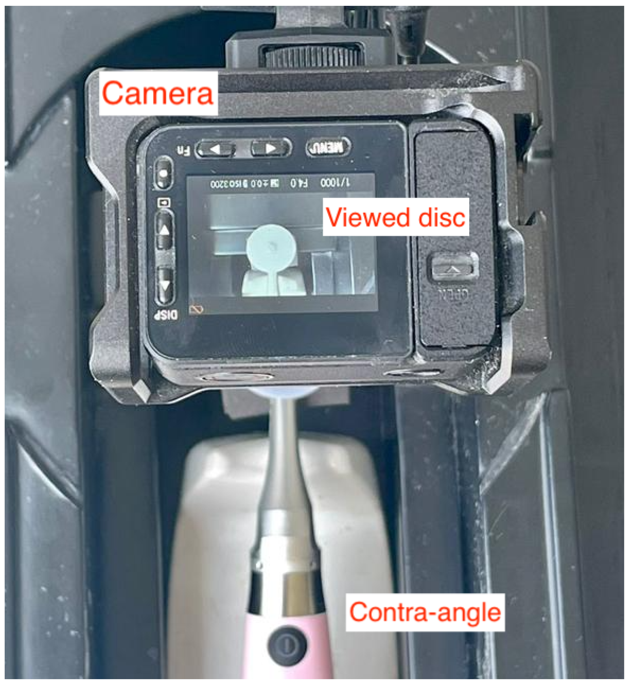
Figure 5 presents the defined hardware scenario to support the execution of the implemented algorithms. A camera is placed on a fixed position with an angle of
from the imaginary plane that contains the rotating disc (usually the ground), with its lens neatly facing it. This positioning, with the camera completely viewing the rotating disc attached on the contra-angle, must be the same for all assessed endodontic motors.
All assessed motors have to be sampled with the same configuration of the high-speed camera if the achieved results have to be compared in some way. In fact, this hardware assembling can be easily altered if required, as long as the disc can be properly identified within the retrieved images.
A final important remark is about the adopted camera position. The way it is, the camera is inverting the movement directions for the engaging and disengaging angles (mirrored images); however, this fact has no practical implications in the proposed method and achieved results.
4.3. Numerical Evaluation of the Motors
The proposed image processing approach combined with the defined experimental scenario and camera configurations can precisely account the movement of the assessed motors. The text file containing the positions of the red dot and the center of the disc is valuable as input data for any algorithm, since they also express a temporal significance row by row. For the implemented algorithm, the computation of angular distances (engaging and disengaging angles) and RPM is performed and displayed as an output, along with the graphical exhibition of the visual module as presented in
Figure 4. In this context, the results for three popular reciprocating motors are presented and discussed in this subsection.
With the introduction of the reciprocating motion, the need for new electric motors appeared. Nowadays, there are several commercially available dedicated motors to perform the reciprocating movement that can be classified into three types: closed motors, closed-but-adjustable motors and open motors. The closed motors are devices that only execute previously recorded reciprocating movements and do not allow update or modification of their kinematics. The closed-but-adjustable devices perform only recorded reciprocating movements registered in their libraries but, through an update, can be upgraded to new kinematics following well-defined rules. Finally, the open motors can be partially or totally programmed to operate in different movements by setting clockwise and counter-clockwise angles, torque and speed. For these groups of motors, while closed and closed-but-adjustable motors offer a reciprocating movement in which the cutting is in a counterclockwise direction, completing a total rotation after three consecutive cycles (in opposition to continuous rotation motors in clockwise direction), the open motors allow more flexibility when defining the way the motors will operate, although proper configuration may be a complex and time consuming task.
In this defined scenario, three popular endodontic reciprocating motors were assessed. The first of them, VDW.GOLD®RECIPROC®(VDW Gold) is a popular closed-but-adjustable endodontic all-in-one motor that bundles other services such as a precise length determination tool for the tooth’s root being treated (for canal preparation), being suitable for preparation in traditional rotary (only one rotation direction) and reciprocating mode. The second motor, VDW.CONNECT Drive®(VDW Connect) is a closed-but-adjustable cordless motor for canal treatment for both continuous rotation and reciprocating movement. The third assessed motor is the Woodpecker®Ai-Motor, a open cordless reciprocating motor that promises to deliver the same services and performance of other popular motors, while being cheaper.
The same acrylic disc with a red dot was attached on each of the assessed reciprocating motors, with the support of a contra-angle. Then, the same camera setting and positioning was adopted, as defined in the assessment scenario setting. For the group of generated images, the proposed method was applied resulting in the computation of the desired parameters.
Table 1 presents the achieved results after the execution of the proposed method.
5. Discussion
As can be seen in the presented results, the assessed motors have different kinematics, although they were all roughly expected to move in the same way [
5,
8,
11]. According to the provided specifications by the manufacturers, the reciprocating mode is preset by default performing 150
CCW and 30
CW at 300 RPM for both VDW Gold and VDW Connect. For the Woodpecker Ai-Motor, the default setting is the same, but its rotation angles can be adjusted between 20–340
(the default setting was assumed in the experiments).
In short, it can be said that the three motors do not move in the expected 150/30 engaging/disengaging pattern initially established for reciprocating motors, and the same concern is valid for their RPM; however, an interesting consideration that can be taken is that the value of is roughly 120 for all of them, achieving after three engaging/disengaging cycles. Actually, this remark may have some practical implications concerning the fatigue of the endodontic files and also in the efficiency of performed procedures, but it still requires further investigation.
Concerning the limitations of this work, we believe that the accuracy and operation characteristics of the employed cameras will be a decisive factor when analyzing the achieved results. Since the algorithm is executed offline already having all sets of images as input, its execution is not a constraint; however, the image acquisition phase is a more critical issue that could compromise the performed assessment.
Finally, based on the described methodology and the achieved results, we believe that the proposed method is ready to support additional research efforts in this area.
6. Conclusions
The particularities of electric reciprocating motors, with rotating movements in opposite directions following an asymmetric cycle, are known as having significant impact on endodontic treatments related to root canal preparations, notably concerning the fatigue and lifetime of endodontic files; however, although potentially beneficial, the movement characteristics of such motors are hard to be assessed, which has forced the professionals to trust information provided by the manufacturers; therefore, computer-assisted solutions to handle this problem are highly welcome, supporting the assessment of the actual kinematics of the motors.
The relevance of reciprocating motors for endodontic treatments has fostered the development of a set of different motors to be chosen, which are available with different prices and promised efficiency; however, since their actual movement patterns are of paramount importance, effective assessment methods are desired to support the best decision when purchasing such tools. In this sense, the proposed approach presents itself as an affordable and practical solution, with promising results.
The proposed method exploits image processing and geometry to compute angular distances over time, keeping track of the performed movements in both clockwise and counter-clockwise directions. With such data, it was possible to compute the maximum engaging and disengaging angles, as well as the achieved RPM, which are basic information to be assessed and compared to the official datasheets of the motors. Such assessment was performed for three popular endodontic reciprocating motors, showing that they behave differently from each other and not in total accordance to the provided data by the manufacturers. With the proposed method and implemented algorithms, different motors can be easily assessed in the future, bringing more relevant information to the area.
Overall, there are other movement parameters to be assessed, such as acceleration and resting time (when the motor is not moving at all), which will be considered in future works. In fact, the performed assessment of three different reciprocating motors are just initial results, since new experiments will be conducted to better support comparisons among different motors available on the market. Moreover, we intend to improve the adopted mathematical model and implemented algorithms in consideration for practical issues such as the inertial momentum of the performed movements, as well as fluctuations in actual accelerations and decelerations within an engaging/disengaging cycle.


 ,
, 


