Article

Concept and Feasibility Evaluation of Distributed Sensor-Based Measurement Systems Using Formation Flying Multicopters

1
Institute of Space Systems, Technische Universität Braunschweig, Hermann-Blenk-Str. 23, 38108 Braunschweig, Germany
2
Institute of Flight Guidance, Technische Universität Braunschweig, Hermann-Blenk-Str. 27, 38108 Braunschweig, Germany
*
Author to whom correspondence should be addressed.
These authors contributed equally to this work.
Current address: Chair of Space Technology, Technische Universität Berlin, Marchstr. 12-14, 10587 Berlin, Germany.
Submission received: 28 May 2021 / Revised: 23 June 2021 / Accepted: 29 June 2021 / Published: 6 July 2021
(This article belongs to the Special Issue Atmospheric Measurements Using Unmanned Systems)

Abstract

:
Unmanned aerial vehicles (UAVs) have been used for increasing research applications in atmospheric measurements. However, most current solutions for these applications are based on a single UAV with limited payload capacity. In order to address the limitations of the single UAV-based approach, this paper proposes a new concept of measurements using tandem flying multicopters as a distributed sensor platform. Key challenges of the proposed concept are identified including the relative position estimation and control in wind-perturbed outdoor environment and the precise alignment of payloads. In the proposed concept, sliding mode control is chosen as the relative position controller and a gimbal stabilization system is introduced to achieve fine payload alignment. The characterization of the position estimation sensors (including global navigation satellite system and real-time kinematics) and flight controller is carried out using different UAVs (a DJI Matrice M600 Pro Hexacopter and Tarot X4 frame based Quadcopter) under different wind levels. Based on the experimental data, the performance of the sliding mode controller and the performance of the gimbal stabilization system are evaluated in a hardware-in-the-loop simulation environment (called ELISSA). Preliminary achievable control accuracies of the relative position and attitude of subsystems in the proposed concept are estimated based on experimental results.

1. Introduction

Unmanned aerial vehicles (UAVs) have been used in atmospheric research since the 1970s [1]. Compared to fixed-wing types, multi-copter UAVs provide high flexibility in operations as they are easier to handle and do not require a runway for taking off and landing. Therefore, multicopters have recently been intensively used for a broad range of applications, from measuring meteorological parameters (such as wind vector [2,3], temperature and humidity [4,5,6], and radiation [7]) to measuring the concentration of trace gases (e.g., methane [6,8,9]) and aerosol [10,11,12,13] in the atmospheric boundary layer. In contrast to classical sampling techniques performed on the ground and at tall towers, UAVs offer high flexibility in the selection of the sampling location and altitude. They fill the gap of sampling the atmospheric boundary layer with high temporal and spatial resolution at scales of typically up to 1 km altitude and to a few kilometers horizontally (e.g., [14]). As a result, it is possible to study spatio-temporal mixing processes, necessary to derive accurate models for distribution dynamics. In applications of UAVs for atmospheric measurements, it is possible either to take air samples for analysis after flights (e.g., [15]), to connect the UAV-based sampling to the analysis instruments on the ground (e.g., [8]), or to perform in-situ measurements on the UAV with optical, chemical or other methods (e.g., [11,12,13]).
In atmospheric measurements, there are some cases where a large absorption path between light source and detector is desired for better results than can be achieved by one UAV. One particular method for the concentration measurement is based on the absorption of electromagnetic radiation, e.g., laser absorption spectroscopy, which requires a large absorption path in the range of several tens of meters for good accuracy [16]. Stereophotogrammetric methods, specially with non-static objects in the scene, also require the deployment of two cameras at rather large distances in the range of several meters to hundreds of meters.
However, current UAV-based solutions for atmospheric measurements mostly focus on using a single UAV which is difficult to deal with in the aforementioned cases. For example, the length and weight of the air sampling lines or tubes are limited by the capacity (in terms of the size and the maximum payload weight) of the UAV [6]. In addition, when instantaneous onboard analysis is desired, the capacity of a single UAV will also require analyzers to be small and lightweight for the integration.
Instead of using a single UAV, the use of distributed UAVs in formation flight can overcome significant technical challenges and financial limitations, which arise from the use of manned aircraft with more space for instrumentation. The distribution of sensors and payloads among several UAVs allows higher coverage area, redundancy, cost efficiency, and even realizability, enabling new applications that would not be achievable with a single UAV or even manned aircraft. In the typical application of laser spectroscopy for determining the concentration of a certain molecule in the atmosphere (e.g., methane), the distribution of the laser source and detector unit between two UAVs means a flexible and less constrained sampling path and hence better measurement quality while avoiding all listed limitations of the single UAV based approach.
One key challenge of such a formation flight is the relative position estimation and control in a wind-perturbed outdoor environment. While several studies tackled the algorithmic issues related to system modeling, state estimation, and control, there are few published works dealing with the challenges of a hardware implementation in wind-perturbed environments. Rekleitis et al. [17] studied quadrotor formation flying using angles-only navigation extracted from a monocular camera and two colored markers installed collinearly on the mutually observing quadrotors. The estimated relative position was directly used to guide the follower quadrotor to keep a fixed position with respect to the leader, exhibiting a position error of around 0.5 m and an orientation error of about 5°. Achtelik et al. [18] used two UAVs flying in formation as a flexible baseline stereo system. They extracted the relative position between the two UAVs using the feature correspondences in the overlapping images. The visual method, however, provides the translation up to an arbitrary scale. To obtain the absolute scale, they used the inertial measurement unit (IMU) measurements. They did not, however, actively control the relative position between the two UAVs since, for stereo imaging, it is only necessary to have an accurate estimate of the relative position rather than a fixed position. In [19] a method of relative position estimation between two UAVs using visual markers was presented. The objective was to evaluate a 360° camera system for the position estimation wherein both UAVs carried a visual marker. The obtained range for good position estimation accuracy was 2.3 m for a marker size of 8 cm × 8 cm which is too small for practical applications. Rafifandi et al. [20] achieved tracking accuracy of 50–115 cm using ground-in-the-loop vision based navigation via fiducial markers and a proportional-derivative (PD) controller. Both leader-follower formation experiments were performed with Parrot AR Drone 2.0 quadrotor UAV of 64 mm diameter and with a mass of 420 g. Such small UAVs are, however, not suitable for carrying heavy scientific payload such as the equipment needed for trace gas measurements.
An additional challenge for the presented science case is payload pointing. Traditional multicopters (all rotors roughly in one plane, symmetric rotors, and no cyclic blade control) cannot simultaneously control position and attitude (apart from heading). A possible solution is the use of a gimbal stabilization system. This is expected to improve the tracking performance and relax the requirements on the UAV control performance. A large body of literature investigates different gimbal configurations and their related control techniques. Rodin et al. [21] reviewed the requirements and design considerations for gimbal based optical imaging stabilization on small UAVs. They noted the effect of gimbal weight on the gimbal jitter (high frequency vibration of the gimbal motors). The heavier gimbals usually have high quality motors for precise position detection and hence are able to stabilize the payload with much less jitter. The characterization of the gimbal performance is usually done using IMUs. Mateo et al. [22] used not only the onboard IMU but also an external means for verifying the stability of the gimbal and realized an accuracy of less than 2°. However, they used only the checkerboard for the attitude estimation.
The main objective of this paper is to investigate and evaluate the application of UAVs formation flying for building a distributed sensor platform under disturbed atmospheric conditions. The contributions of this paper are as follows.
Firstly, this paper proposes a new concept of distributed measurement technique using tandem flying multicopters as a distributed sensor platform. Preliminary requirements for such a system are estimated.
Secondly, the accuracy of the position estimation and control of current UAV systems is evaluated under real atmospheric conditions. Characterization of the position estimation sensors and controller is carried out using different classes (hexacopter and quadcopter) of UAVs.
Thirdly, the performance of sliding mode control (SMC), which is planned to be used for the accurate relative position control, is evaluated in a hardware-in-the-loop (HIL) simulation environment. In order to take wind disturbances into consideration, a wind disturbance model is extracted based on the measured flight data.
Lastly, the performance of the gimbal stabilization system is evaluated in the laboratory environment.
It should be mentioned that, as there was no defined case study to prove the proposed concept and the relative position controller was not implemented for the flight, flight tests were only conducted with individual UAVs to explore the achievable performance of a single UAV in the concept.

2. Methodology

2.1. Concept of a Distributed Sensor Platform for Atmospheric Measurements

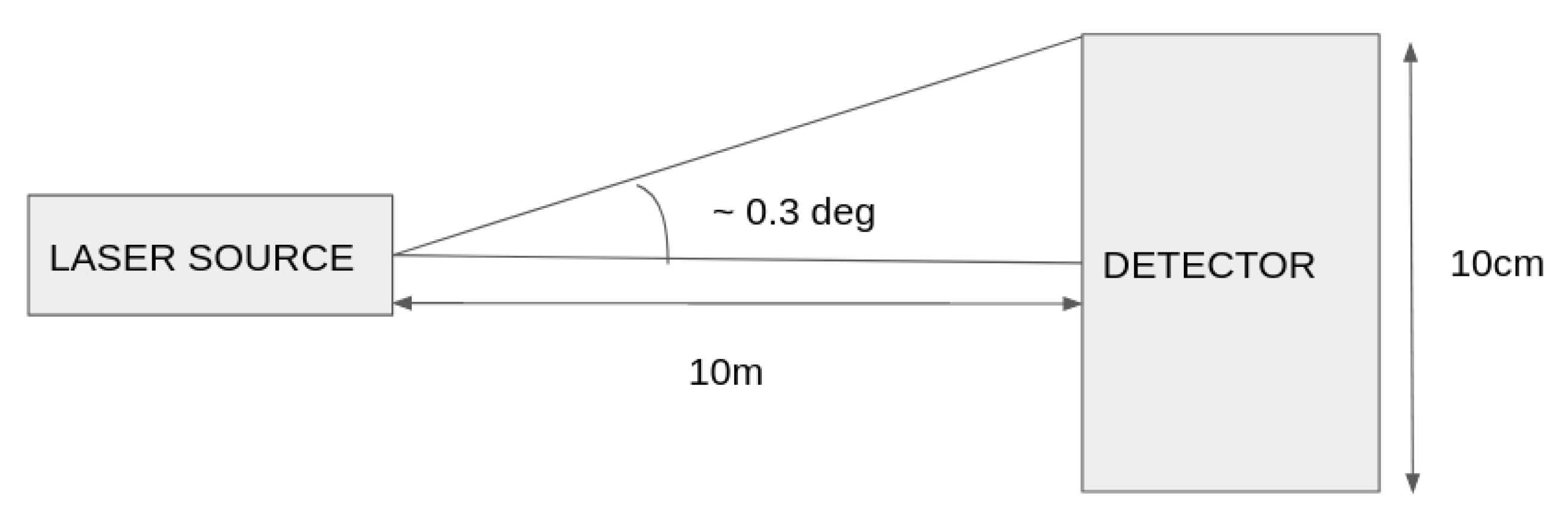
This paper proposes the use of two UAVs flying in formation as a distributed platform for atmospheric measurements. For example, one UAV carries the laser source of the system, while the other one carries the detector, potentially leading to accurate (due to the longer path length) and flexible (i.e., higher altitudes and larger sampling volumes) gas concentration measurements. Figure 1 shows the basic concept of a proposed distributed optical system along with assumptions on the position accuracy to ensure a functional system. Assuming a fixed detector in the inertial frame, a deterministic error source model and zero laser beam divergence, the size of the detector area determines the required relative pointing performance of the laser source. A larger detecting area can tolerate higher pointing errors but encounters practical payload size and weight limitations. As an example, as shown in Figure 1, a detector diameter of 10 cm (realistic size for a heavy UAV such as DJI Matrice M600) and a path length of 10 m between the two UAVs can tolerate pointing errors up to 0.3°. The UAVs must keep a minimum distance of 10 m along the measurement axis. It has to be noted that these requirements are based on the assumption that there is no relative movement between the laser source and the detector. In practice, however, the relative movement between the laser source and the detector is unavoidable. Moreover, both UAVs need to be controlled to avoid relative movements even under adverse turbulent wind conditions of the lower atmosphere where such measurements have to be carried out, which are described for typical situations in Section 3.
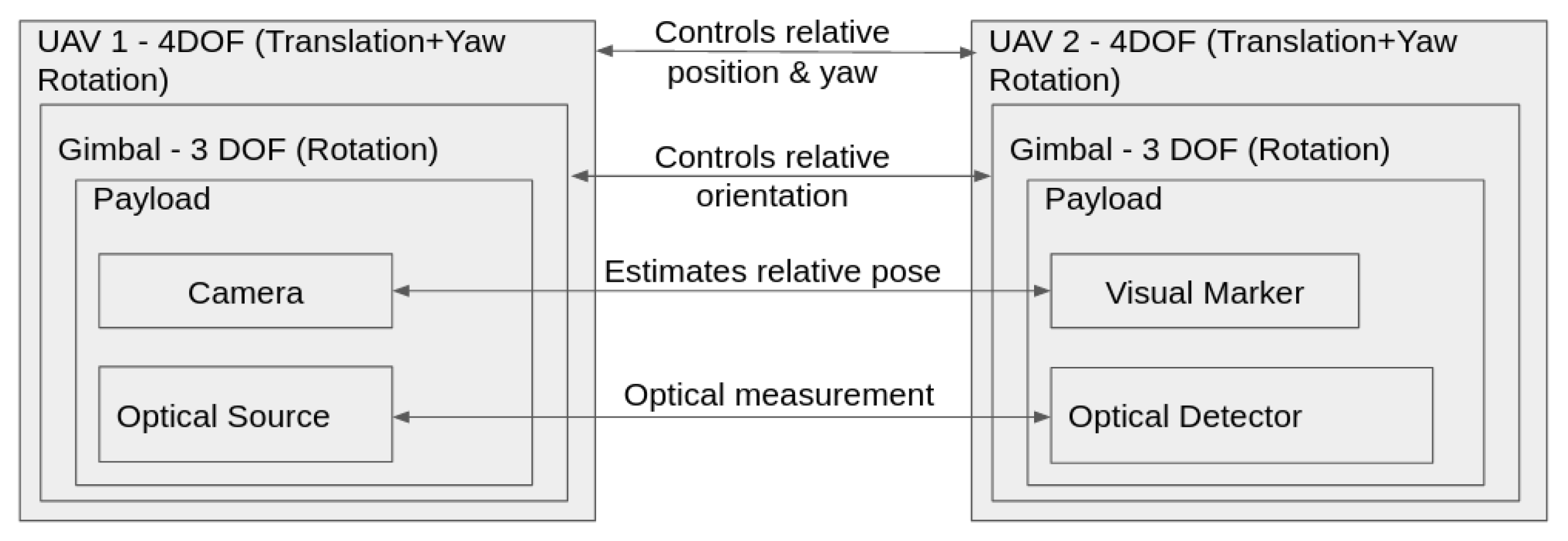
The introduced concept, however, places strict requirements on the control performance of the UAVs which need to keep the sensors oriented close relative to one another. It is known that a multi-copter UAV is underactuated and hence not all six degrees of freedom (DOFs) are independently controlled. With effective four DOFs, the multicopter can control the altitude, yaw, pitch, and roll independently, but the movement in the horizontal plane is always accompanied by the roll or the pitch motion. In order to fulfill the position and pointing requirements, a gimbal stabilization system is proposed for the overall concept in Figure 2. Two participating UAVs are multi-copters and equipped with a three-axis gimbal stabilization system. The UAVs maintain the relative position (horizontal and vertical plane) between each other as fixed as possible. Due to the external disturbances and inherent sensor and controller inaccuracies, the UAVs would tilt along the pitch and roll axes. The three-axis gimbal balances these angular disturbances to keep the orientation of the payload in a fixed state. When two gimbal systems are used to keep the respective orientation between the two payloads integrated on these gimbals, the relative orientation error between the two payloads can be determined from a camera and visual markers system. The relative orientation controller would minimize this error using a closed-loop feedback.
To evaluate the feasibility of the concept, several topics need to be addressed: (I) the state knowledge accuracy of both UAVs characterizes the onboard estimation of attitude, rates, position, velocity, and time. (II) The performance of the gimbal stabilization system places requirements on the control performance of the UAV. (III) The transient and steady state pose control performance of both UAVs defines the operational mode of the proposed concept.
This work focuses on the last two points. In particular, experiments are conducted to evaluate the performance of the gimbal stabilization system. Flight tests are performed with different UAVs to characterize the operational environment (in particular the turbulent atmospheric flow) and the actual accuracy of the so far used commercial off-the-shelf position estimation sensors and flight controllers.
To circumvent the lack of accurate position estimation in outdoor flight tests, the proposed controller is evaluated in a controlled laboratory environment called ELISSA, an air-bearing table equipped with a state-of-the-art motion capture system. The obtained outdoor flight data is used as input to develop realistic models to simulate disturbances (e.g., turbulence effects on UAV dynamics) in ELISSA. The approach used is based on the determination of control inputs required to generate aircraft angular and translational rates in controlled laboratory conditions that are consistent with rates observed when flying in atmospheric turbulence.

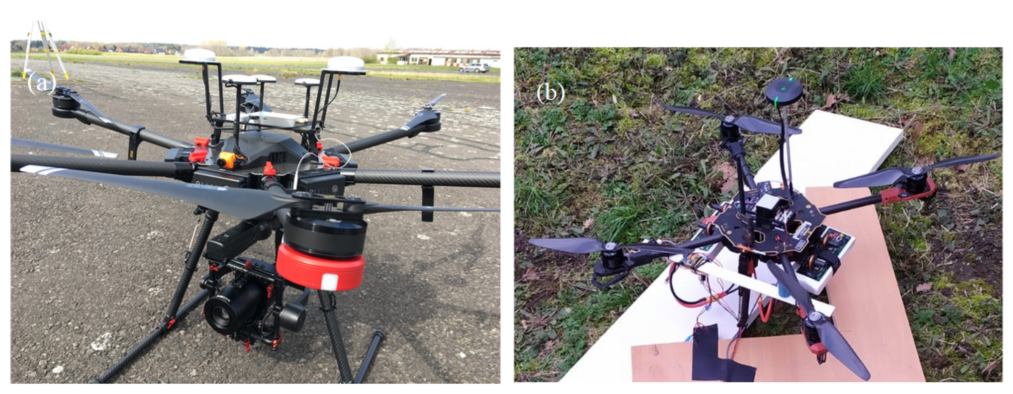
2.2. Flying Platforms

Two different multicopters, a DJI Matrice M600 Pro and a Tarot X4, as shown in Figure 3, are used for this study. The detailed specifications of both multicopters are provided in Table 1.

2.2.1. DJI Matrice M600 Pro

DJI Matrice M600 Pro is a commercial grade heavy lift UAV capable of carrying payloads of up to 5 kg with a flight time of more than 20 min. The UAV uses a triple redundant global navigation satellite system (GNSS) and IMU system for state estimation in the base configuration. It is possible to have an additional dual real time kinematics (D-RTK) position and attitude estimation system for centimeter-level accuracy and accurate attitude estimation even under high magnetic interference situations. The system consists of two units, one mounted on the UAV (called air unit) and one fixed on the ground (called base unit) with known surveyed position. The air unit has two dual band antennas at a fixed separation of 31 cm for precise heading estimation. The dual frequency capability takes advantage of the multi frequency signals from the newer GNSS satellites for faster and reliable position fix, even with less number of GNSS satellites in view. The base unit with known calibrated position can calculate the errors in the GNSS signals. Based on base station measurements and the carrier phase measurements of the used GNSS signals, nearby GNSS receivers can calculate their positions very accurately. This concept is called real time kinematics which is a type of differential GNSS. As per the manufacturer description, the use of RTK allows a position accuracy of up to 2 cm. The UAV can be controlled from standard manufacturer applications. Custom control softwares can be developed either using a mobile software development kit (MSDK) available for Android OS or iOS, or onboard SDK with a companion computer onboard the UAV directly connected to the flight controller. The flight controller hardware used is the DJI A3 which has a DJI proprietary firmware installed which is not open for user customization. An onboard computer (Nvidia Jetson TX2) is used within the robot operating system (ROS) to log all the data in a rosbag file, which also contains the timestamp when the data is acquired. Only IMU data (linear acceleration and angular rates) is available as raw data. The position data, GNSS or RTK (at 10 Hz) is always fused with the IMU data (at 400 Hz) for a fused solution (published at 100 Hz). Although the flight controller also records all the data, only a few data fields are openly accessible.

2.2.2. Tarot X4

Tarot X4 is a lightweight quadcopter with a single GNSS for position estimation and a ProfiCNC Pixhawk flight controller which has triple redundant IMU and a barometer for height estimation. As an autopilot, the PX4 open source firmware is installed. The firmware allows various settings to be changed such as the type of the control algorithm. It is also possible to easily extend this firmware for future scenarios. The Tarot UAV’s data is logged on a SD card onboard the flight controller which contains one log for each power cycle of the UAV. The log is in a PX4 format, but since the format is openly available, the data was initially processed using the open source tool pyulog and flight review [23]. Additionally, this UAV was fitted with a RTK system (SparkFun uBlox F9P RTK) for better accuracy of position estimation.

2.3. The ELISSA Lab

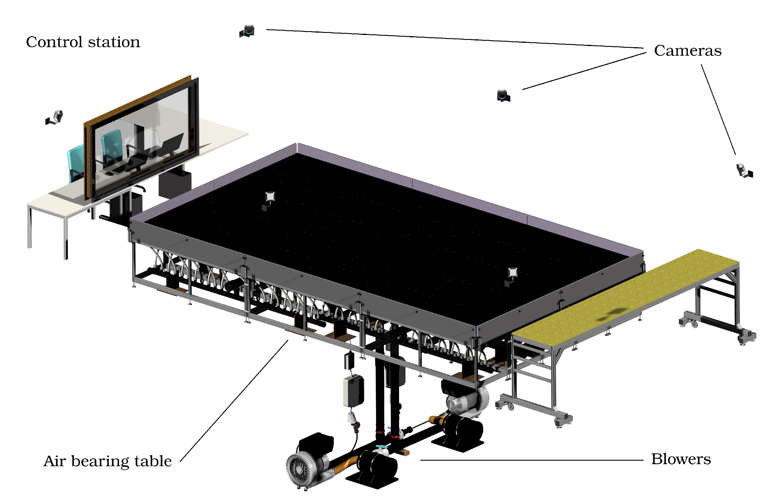
The Experimental Lab for Proximity Operations and Space Awareness (ELISSA) is a facility at the Institute of Space Systems of TU Braunschweig. The goal of ELISSA is to enable the emulation of weightlessness and contact dynamics of spacecraft in orbit. ELISSA (as shown in Figure 4) is mainly composed of four parts: the aeromechanical subsystem, the motion capture subsystem, the mission control subsystem, and the free flyers (FF) subsystem. The aeromechanical subsystem transports air mass and generates the air cushion on the air-bearing table for the FFs. Unlike most air-bearing tables in research facilities, where satellite mockups need to incorporate tanks of high-pressure gas to generate air cushions, the air-bearing table in ELISSA environment can generate air cushions by itself with high-pressure airflow based on the SmartNozzle technology of the company CoreFlow [24] and thus, enables a long duration of experiment. A maximum weight of 30 kg can be floated per 0.05 m 2 . The OptiTrack [25] motion capture subsystem with six Prime 17W cameras measures the position and the attitude of mockups. It can achieve a state knowledge accuracy of 0.25° in attitude and 1 mm in position. The mission control subsystem, which is based on ROS, allows the operation of the whole infrastructure. It generates command signals for the whole environment to conduct the experiment. At present, satellite mockups can have three-DOF motions including two DOFs for the translation and one for the rotation.
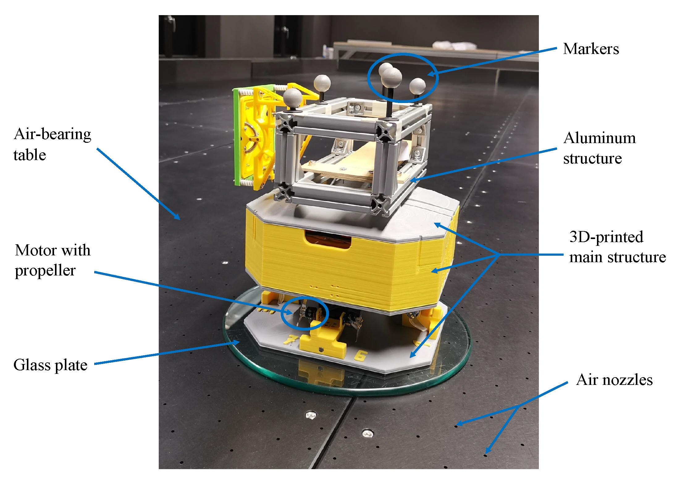
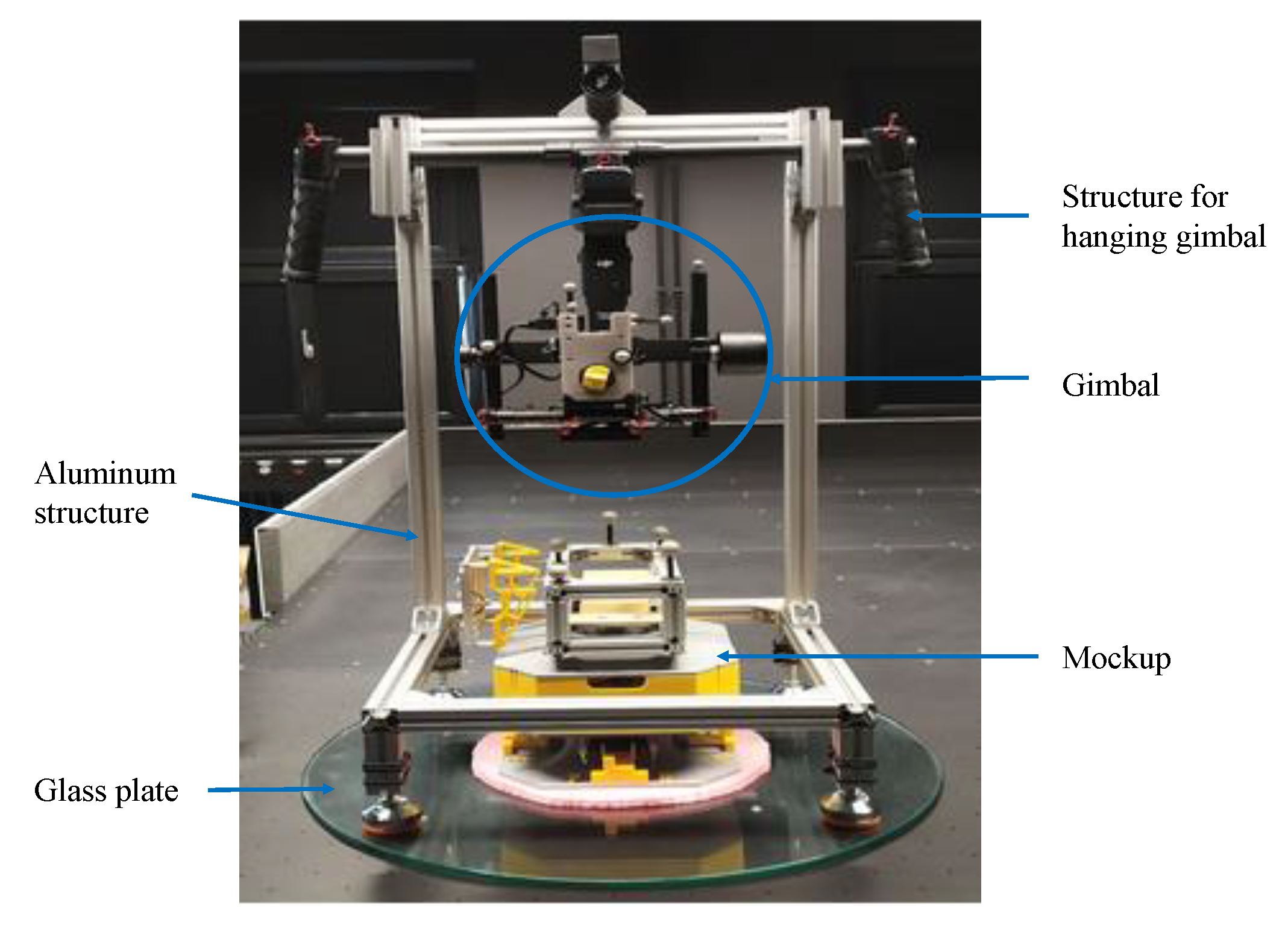
The 3D-printed main structure of the mockup (as shown in Figure 5) has a dimension of 22 cm × 22 cm × 26 cm and is used to mount 8 motors with propellers, various printed circuit boards (PCBs) and a LiPo battery. On the top of the main structure, an aluminum structure is fixed for installing payloads and markers for the motion capture system. The total weight of the whole structure (the 3D-printed main structure and the aluminum structure) with the LiPo battery is 2.87 kg. A Raspberry Pi is used as the onboard computer to control the mockup. When placed on a glass plate with a diameter of around 30 cm, the mockup can float freely on the air-bearing table.
Based on sliding mode control (SMC) technique, a controller is developed to control the motion of the mockup. With the conventional method of modeling the dynamics of a rigid body (i.e., position vectors for the translation and attitude parameterization for the rotation), two controllers are needed, of which one is for the translation and the other for the rotation. For the SMC design of ELISSA, dual quaternion parameterization is implemented to describe the translation and rotation of the mockup simultaneously. The developed dual quaternion-based SMC [26] can generate command forces and torques for the translation and the rotation, respectively, at the same time. Thus, based on dual quaternion parameterization, only one controller is needed instead of two, which makes the mission control subsystem more compact. The developed SMC controller is a pose (i.e., position and attitude) tracking controller which can be used to track a predefined pose trajectory.
Although ELISSA is designed to simulate the weightlessness and contact dynamics of spacecraft in orbit, it can also be used as a testbed to investigate the concept of distributed sensor platforms in the current project. The reasons are as follows.
First, since the payloads (namely the laser source and the detector) are expensive and easy to be damaged, it would be very risky to directly test the concept with the real payloads in flight. In this perspective, ELISSA offers a safe test environment for the preliminary validation of the concept. To be specific, both the laser source and the detector can be floated on the air-bearing table in ELISSA to simulate the in-plane relative motion during the flight. Thus, insights can be obtained for the concept development without risking expensive payloads.
Next, the motion capture system in ELISSA can achieve high accuracy in measurements (0.25° in attitude and 1 mm in position). As there is a high requirement on the control performance of the multicopters and the gimbal system, the ELISSA environment can be used to accurately assess the achievable performance of the proposed concept.
Last, since SMC is chosen as the control technique for the relative position control in the proposed concept of distributed sensor platforms, ELISSA can provide the HIL environment to evaluate the performance of SMC. The experience and lessons learned with SMC using ELISSA can be helpful for the implementation of SMC in the proposed UAVs formation flying.

2.4. Wind Disturbance Model Extraction

There is a large body of literature dealing with extraction of wind disturbance models from flight data. In [27,28,29], a dynamic model of UAV is used to extract the wind disturbance from onboard sensor data (e.g., IMU accelerations, angular rates, and attitude). To create a dynamic model, complicated aerodynamic tests were carried out in a wind tunnel for obtaining the necessary aerodynamic, inertial, and thrust relationships for the UAV. This was, however, not practical for our project. In order to evaluate the performance of SMC under wind disturbances in ELISSA, a model of wind disturbance suitable for real-time HIL implementation is needed.
Inspired by the control equivalent turbulence input (CETI) method in [
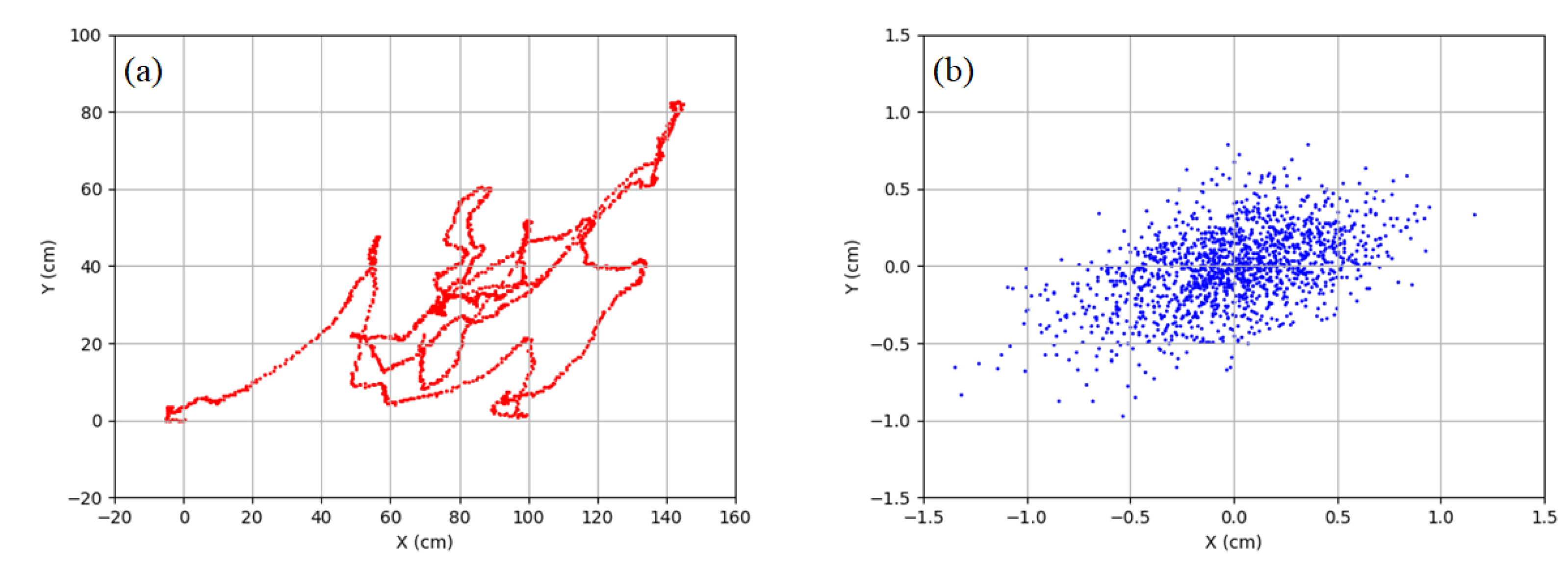
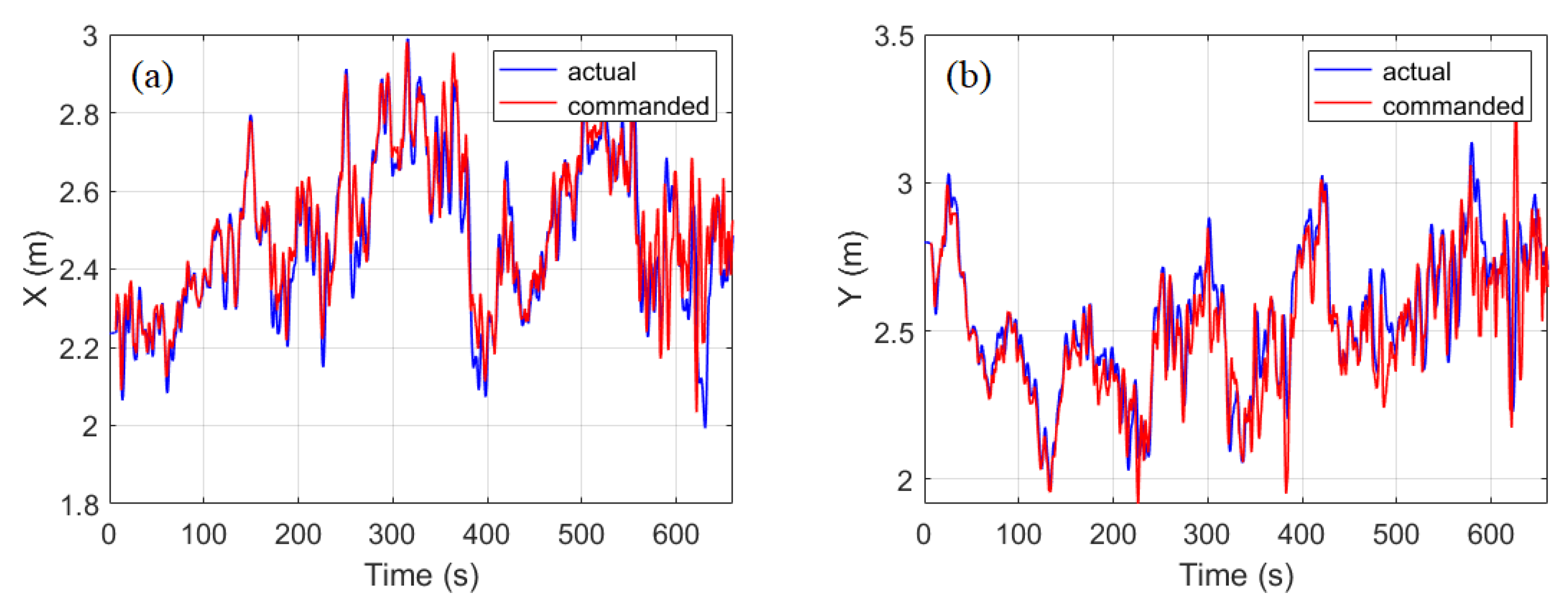
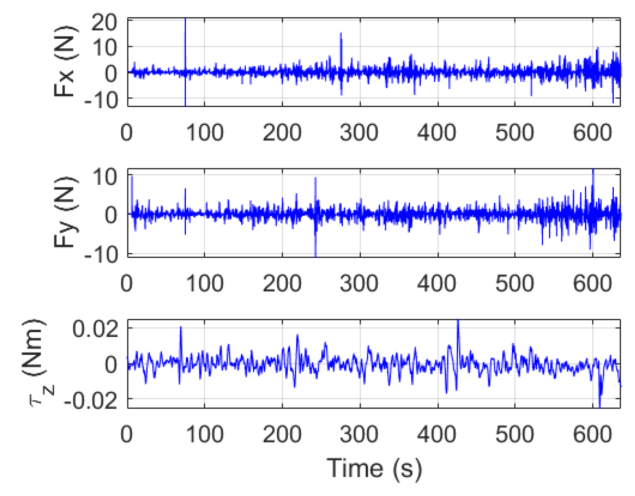
30], a relatively easy way to extract wind disturbance is proposed to preliminarily study the effect of wind disturbance using ELISSA. The basic idea is to let the mockup simulate the measured horizontal movement of UAVs in gusty winds and then record the time history of control commands of the mockup when it tracks the reference movement. The recorded control sequence can be regarded as the disturbance the mockup will experience in the wind. The extracted pseudo wind disturbance model is added to the guidance, navigation, and control (GNC) system of ELISSA as external disturbances. The translational reference trajectory is based on measured motion of UAVs in the XY plane. The yaw angle is assumed to be zero in the reference motion. As only position information in the measured data is used, a numerical differentiation method is used to calculate the reference velocity and acceleration. In order to reduce the influence of the measurement noise on the differentiation, the measured flight data is smoothed. The smoothed position information, the calculated velocity, and acceleration are fed into the dual quaternion-based SMC as the translational reference trajectory.
However, when using the above mentioned method to extract wind disturbances for experiments on the air-bearing table, the following issues should be noted: First, the reference trajectory (i.e., the measured flight trajectory of UAVs in XY plane in gusty winds) is actually a result of the regulation control of the UAV and wind disturbances. As a result, the extracted disturbance forces are mixed with control efforts of the UAV’s controller. Second, as the reference trajectory needs to be tracked in the methodology, the control accuracy of tracking the reference trajectory based on SMC also affects the obtained results. Third, when different mockups are used, it needs to run the trajectory tracking experiment again using the same reference trajectory in order to extract the wind disturbance forces.
Although there are drawbacks in the proposed method to obtain the wind disturbance model, in the future, it can still be used for the evaluation of SMC and the gimbal system for the proposed concept.

3. Results and Discussion

This section presents the results of two experiments using UAVs (including the ground reference test and the position hold test) and three experiments in ELISSA (namely experiments for SMC performance evaluation, wind disturbance model extraction, and gimbal characterization). All the UAV experiments were conducted at an abandoned airport in Edemissen in Lower Saxony, Germany.

3.1. Ground Reference Test

The objective of this experiment is to determine the drift over time of the position estimation sensors, specifically to make a comparison between the GNSS and the RTK based position estimation. In the experiment, the UAV was kept stationary on the ground for a period of 10 min, within which the data from both GNSS and RTK system were logged. The UAV was located under an open sky free of obstacles to receive high-quality GNSS signals. The RTK base station was located with a similar sky view and was only 20 m away from the UAV. In the absence of more accurate position measurement sensors, the set point of the UAV was assumed to be the mean of the RTK observations.
Figure 6 shows the comparison of drift in the position estimation from the GNSS and RTK where all observations are with respect to the set point (the origin in the plots). As shown in Figure 6a, the GNSS measurements show a continuous drift of up to 1.2 m from the assumed correct location of the UAV, which indicates a drift rate of 12 cm/min. The RTK data in Figure 6b, on the other hand, remains highly precise with a drift of only 2 cm over a similar time interval. Thus it can be assumed that the relative accuracy of the RTK is in this range even if the absolute accuracy may not.

3.2. Position Hold Test under Different Wind Gust Levels

The objective of this experiment is to evaluate the control performance of the multicopter and characterize its movements when commanded to hold its position at a fixed height in different wind conditions.
In this experiment, the UAV was commanded to hover at a fixed height for approximately 10 min and the data was logged for this duration. The wind speed was measured at 2 m altitude from the ground with a handheld cup anemometer. The measurements were done multiple times during the recording flight and wind levels are listed in Table 2. Level 1 corresponds to relatively calm conditions with occasional gusts of up to 2 m/s. Wind speeds under level 2 can be classified as moderate for the UAV flight and that of level 3 to be extreme. The UAV was always positioned at almost the same ground position with approximately the same heading (between 100°–108°).
Due to the better position estimation precision of RTK sensors, as already demonstrated in the ground reference test, only the RTK-based positioning results under different wind conditions are compared. The comparison is shown in the Figure 7, Figure 8, Figure 9 and Figure 10 for the DJI Matrice M600 UAV. This is followed by Figure 11 in which a summary of the root mean square error (RMSE) of all state parameters is presented for DJI UAV. Similar comparison is done for the Tarot UAV in Figure 12.
Note that, in Figure 7, Figure 8, Figure 11 and Figure 12, the X, Y, and Z axes represent the forward, lateral, and vertical motion directions of the UAV, respectively.
Figure 7 illustrates comparison for the position of the UAV in different wind conditions. In wind-still conditions (wind level 1), the variations of the position of the UAV in the 3D space are mostly less than 10 cm with occasional movements up to 20 cm. However, under wind level 2 conditions, the position of the UAV shows variation of high amplitude up to 30–40 cm, which increases to 50 cm under wind level 3. It is observed that, over a short duration (up to 5 s), the UAV is able to hold its position with a drift of only a few centimeters. The maximum movement occurs only over slightly longer time intervals meaning that the velocities of the drift are very small. This is also reflected in RMSE of the position with respect to the set position as shown in Figure 11. On the average, the RMSE amplitudes are double for UAV position under wind level 2 in comparison to that of wind level 1.
A similar effect is observed for the UAV velocities as well. Figure 8 compares the velocities of the UAV in different wind conditions. Under relatively calm conditions (wind level 1), the UAV hovers with velocities below a few cm/s. This small movement can be attributed to the error/bias in the sensors, imperfections in actuators, and the flight controller. When faced with wind gusts in the order of 2–5 m/s (wind level 2), the UAV shows much higher amplitude movements of velocities up to 20 cm/s. With much higher wind gusts as observed with wind level 3, the UAV makes sudden movements of up to 40 cm/s. However, it should be noted that the Z velocity (vertical velocity) does not show such drastic differences. This is due to the fact that wind gusts are usually sideways and mainly affect the movement of the UAV in the horizontal plane whereas the movement in Z axis is only loosely coupled to the sideways disturbances.
The angular rates of the UAV in different wind conditions are shown in Figure 9. Changes of angular rates in high frequency are observed. This is because the position controller constantly updates the required vehicle attitude to keep a steady position and the attitude controller operates at much higher frequency to maintain this attitude in comparison to the position controller. The amplitudes of the angular rates depend on the external disturbances as well which can be seen in the pitch and roll rates of the UAV in wind. The amplitudes of pitch and roll rates with wind level 2 are almost double those of the wind level 1. Moreover, the rates for the vehicle yaw are very similar (largely under 0.1°/s) for both conditions attesting to the fact that the disturbances affect the tilt axes much more than the azimuth axis.
Figure 10 shows the attitude of the UAV in different wind conditions. Under relatively calm conditions (wind level 1), the attitude of the vehicle is nearly steady. Under constant wind disturbances of level 2 and 3, the UAV has to keep a certain attitude to hold its position. This required attitude is determined by the position controller in each update step and provided to the attitude controller as the set point. Depending on the direction of the wind, the pitch and/or roll are directly affected by the wind velocity. The variation of these two attitudes is seen clearly in Figure 10 where the values vary from 0° to −5° and −7° for level 2 and 3, respectively. Many researchers (e.g., [31,32,33]) in the past have used the vehicle attitude to indirectly estimate the wind speed and direction. This method depends heavily on the accuracy of the attitude estimation accuracy. An error of 0.5°/s, which is the norm for currently available cheap IMUs, could lead to an error of around 0.7 m/s [8] in the wind velocity estimation.
Figure 11 compares the RMSE of the position, the velocity, the attitude, and the angular velocity of the UAV in different wind conditions. The RMSEs were calculated from the data used for Figure 7, Figure 8, Figure 9 and Figure 10.
A similar evaluation was carried out for the Tarot X4 UAV and the summary of the results is presented in Figure 12. The measurements for the wind level 1 conditions are missing in this case since the UAV did not have a RTK-GNSS based position estimation sensor during the tests conducted under wind still conditions. A comparison for the position performance shows that under wind level 2, the UAV is able to hold the position in a comparable manner. However, under the extreme wind level 3, the Z component (vertical motion) performs much worse than the DJI M600. One possible reason for this is the inaccuracy of the relatively cheaper barometer sensor used in the PixHawk 2 flight controller.
For the UAV velocity and attitude, the UAV behaves in a similar manner to DJI M600 for wind level 2 but performs much worse under higher wind gusts which are encountered under wind level 3. The worse performance under extreme wind gusts can be partly attributed to the much lower weight of the Tarot X4 UAV leading to higher sensitivity to higher wind disturbances. Other factor which also leads to this difference is a much better calibration and controller optimization of the DJI M600 UAV since it is a commercial UAV.

3.3. SMC Performance Evaluation

The performance of SMC is evaluated in a regulation control case in ELISSA. In this test scenario, the mockup is commanded to keep its position at (2 m, 2 m) on the air-bearing table and keep a yaw angle of 0°. Figure 13 shows the results of the regulation control using SMC after tuning control parameters. It can be seen that, with tuned SMC parameters, the position control accuracy is around 2–5 cm and the attitude accuracy is around 2°–4°.
There are many factors affecting the control accuracy of SMC in the experiment. First, the flatness of the air-bearing table is one factor that contributes to the control error of the position. When the air-bearing table is not flat, gravity of the mockup will drive it away from the commanded set points, which increases external disturbances for the mockup. Theoretically, suitable tuned parameters of SMC can achieve high control accuracy. To be specific, there is a parameter in SMC which reacts against external disturbances. When the parameter is set larger than the upper bound of the external disturbances, the system in the sliding mode will be insensitive to external disturbances. In the derivation of SMC for ELISSA, the upper bound of the external disturbances is assumed to be known. However, in practice, the upper bound is difficult to be obtained and has to be estimated for the application. When the upper bound of external disturbances is estimated as a very large value, it causes chattering, i.e., the switch of control in high frequency. Although the boundary layer method [34] (i.e., replacing the sign function with the saturation function) is used to alleviate the chattering phenomenon, a good estimation of the upper bound of external disturbances will still improve the performance of the SMC controller. Next, the dead zone of motors used for the mockup contributes to the control error of SMC as well. When small control forces are commanded for the fine position holding, the existence of the dead zone in motors will result in zero control efforts. Last, since SMC is a kind of model-based control method, uncertainties in mass property (i.e., mass and moment of inertia) also degrade the control performance of SMC. External disturbance estimation based on observer methods and adaptive control methods for parameter uncertainties are possible solutions to improve the control performance of SMC.

3.4. Wind Disturbance Model Extraction

The reference trajectory (data of measured trajectory using RTK for the height of 20 m) was tracked using the developed dual quaternion-based SMC. The comparisons between the reference trajectory and the real trajectory are shown in Figure 14. From the time histories of X and Y, it can be seen that the reference trajectory can be followed. However, because of the control accuracy, the reference trajectory cannot be tracked exactly.
Figure 15 shows the recorded control commands by SMC when tracking the reference trajectory. These control commands are the extracted wind disturbance model. Certain large control commands are observed in the control sequence. These large control commands result from the sharp turns in the reference trajectory.

3.5. Gimbal Characterization

Figure 16 shows the experimental setup for the gimbal characterization. The objective of the tests is to evaluate the gimbal balancing performance under atmosphere wind conditions. The performance is evaluated in a controlled environment ELISSA in a HIL mode. The setup consisted of a mounting structure made of aluminum profiles. The gimbal was fixed along with a simulated camera payload on this mounting structure. The structure was placed together with a mockup acting as the UAV, described in the previous section, on a glass plate. This made it possible for the combined movement of the mockup and the gimbal structure.
Initial tests were done to verify the capacity of the mockup to move the whole structure with the required speed. After these checks, two tests were done for the gimbal characterization. The first test was a calibration test without active mockup movement to characterize the baseline behaviour of the gimbal system. This included keeping the gimbal steady for a few minutes and calibrating the initial angles. Afterwards the gimbal was commanded to move to its end points along all control axes. This was followed by another steady state pause. In this experiment consecutive end point movement test was carried out for the yaw and pitch axis. Three such test sequences were done with a pause of a few seconds between the tests. A clear coupling between the yaw and roll axis can be seen in Figure 17. The roll follows the same sinusoidal pattern as the commanded yaw movements with an amplitude of 2.5°.
The second test with the complete setup was to follow an input square trajectory to characterize the gimbal behaviour during motion. The test setup was commanded to execute a square trajectory of 1 m length. The gimbal should be able to maintain a constant pitch and roll during the motion since the test setup cannot make any movements along these axes. Figure 18, however, shows that during the movement of the test setup, the gimbal payload experiences regular movements in the pitch axis of less than 1.5° and similarly the roll axis is more stable with values going maximum to 1°. During the trajectory following, the mockup also changes its yaw attitude and the gimbal should follow this. The gimbal attitude lags behind that of the mockup in this regard with an angular difference of up to 5° at any given time. For the proposed application, however, this is not a problem since the UAV is able to maintain the yaw attitude within 1° even under the higher wind level 3.

4. Conclusions

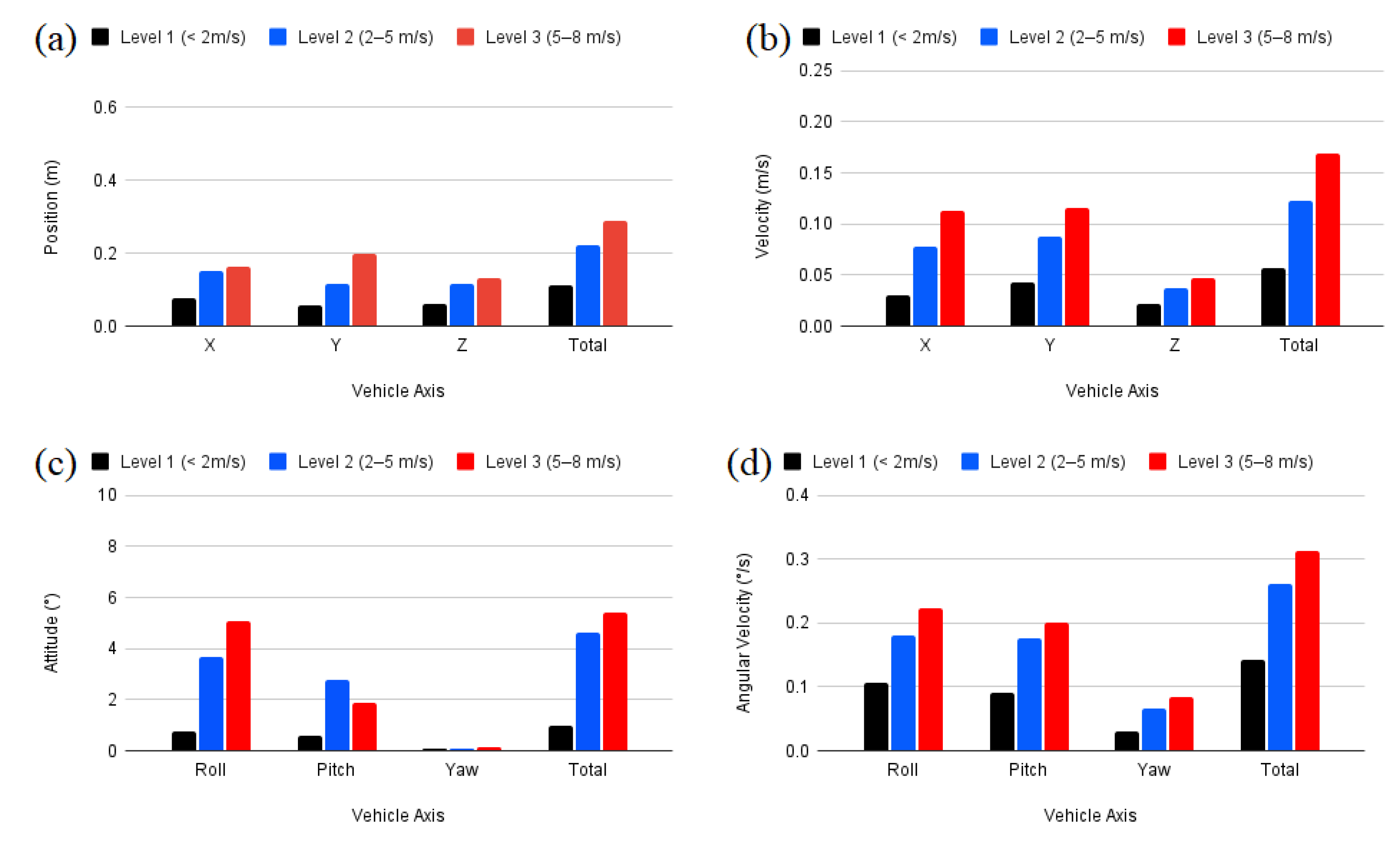
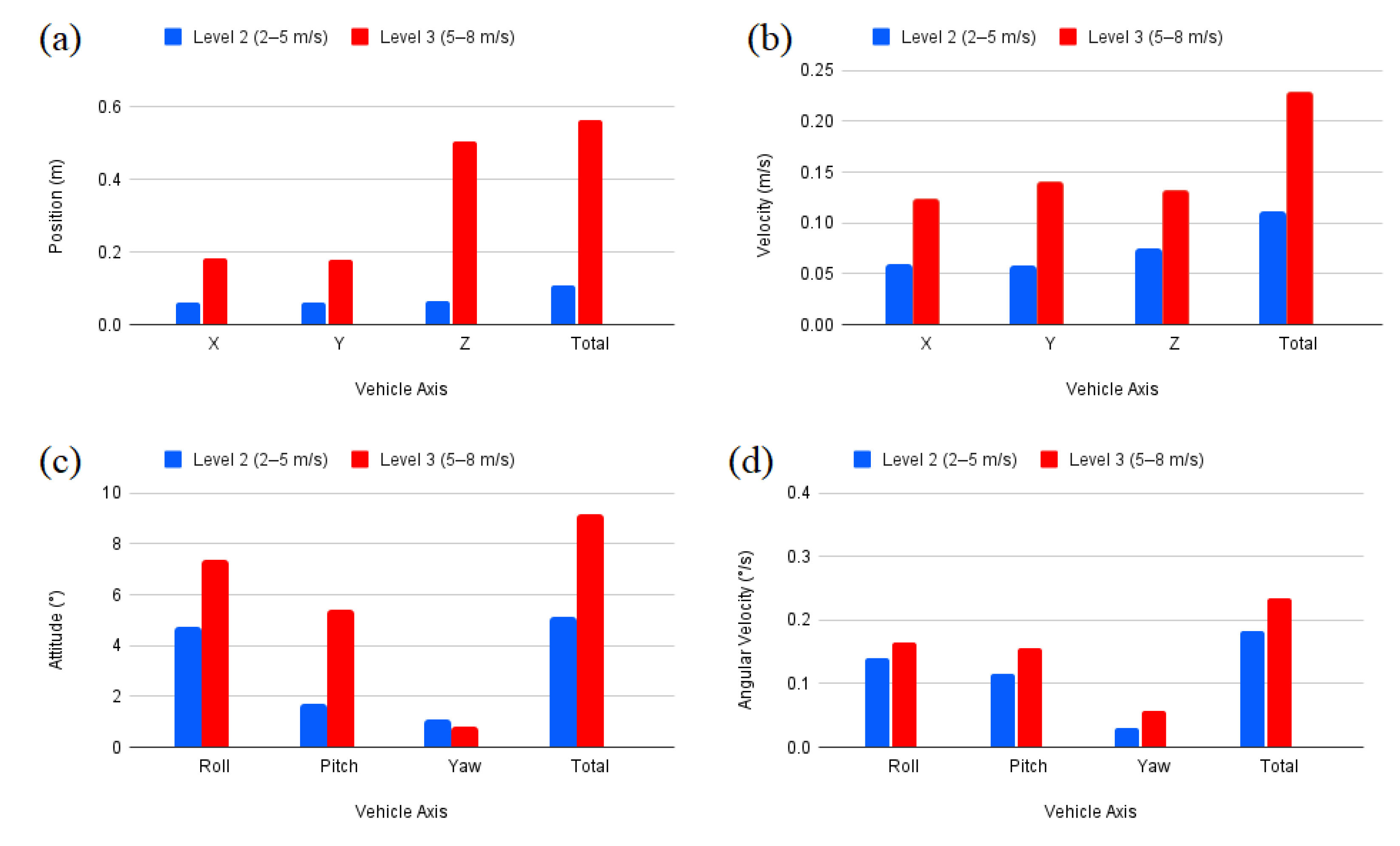
This paper proposes to use multicopters in tandem flying as a distributed sensor platform for optical atmospheric measurement. Gimbal stabilization systems are introduced to achieve the high pointing performance of the payloads. Preliminary requirements on the control accuracy of the relative position and attitude of the components are estimated. Flight experiments using off-the-shelf UAVs under different wind conditions were conducted to evaluate the accuracy of sensor measurements and the positioning control. Compared with GNSS alone, RTK based position control provides more precise position estimation and is recommended for the tandem flight application. In terms of the sensors, the flight controller, and payload capacity, DJI M600 UAV has better performance than Tarot UAV for the proposed concept of distributed optical measurements using tandem flying. Specifically in wind speeds of more than 5 m/s, the much smaller Tarot UAV performs much worse. An increase in weight increases the wind tolerance. It is therefore recommended to use a higher weight class (>10 kg MTOW) UAV for applications under extreme wind conditions.
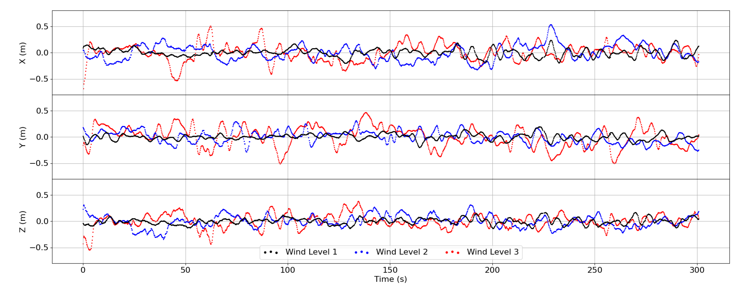
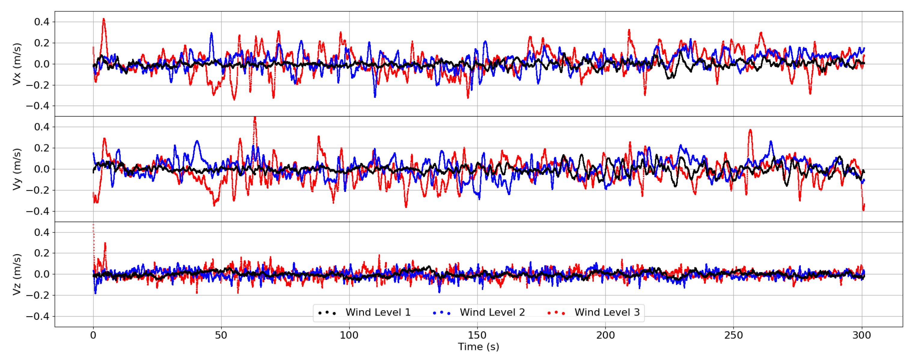
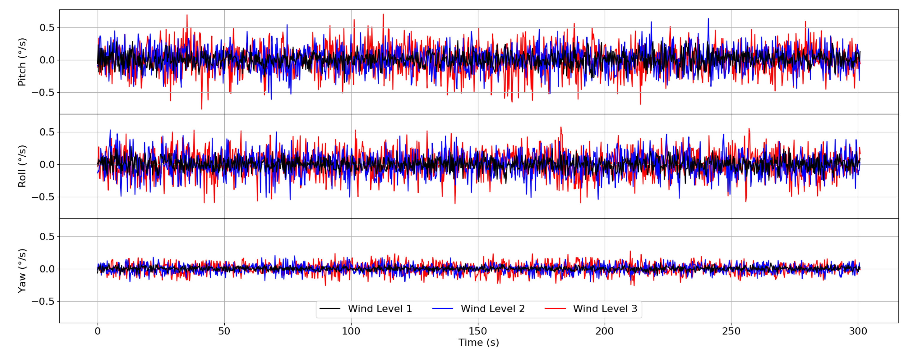
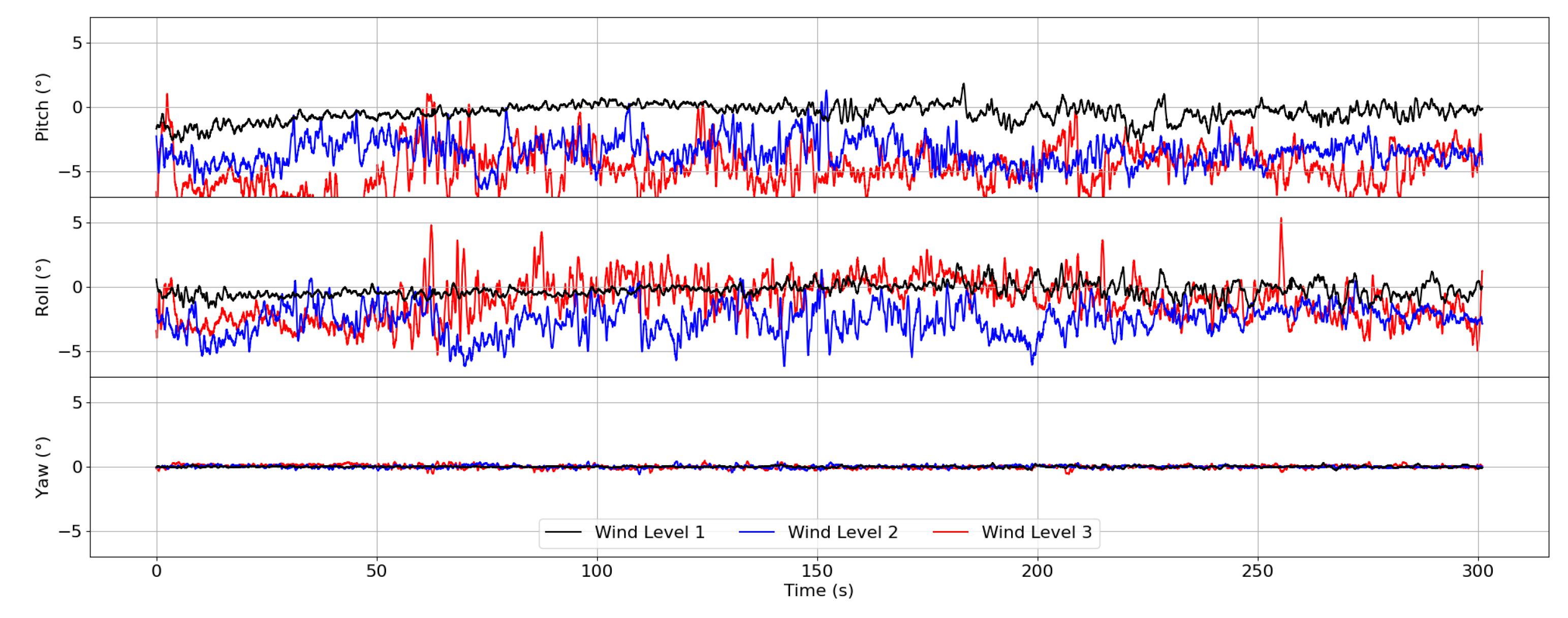
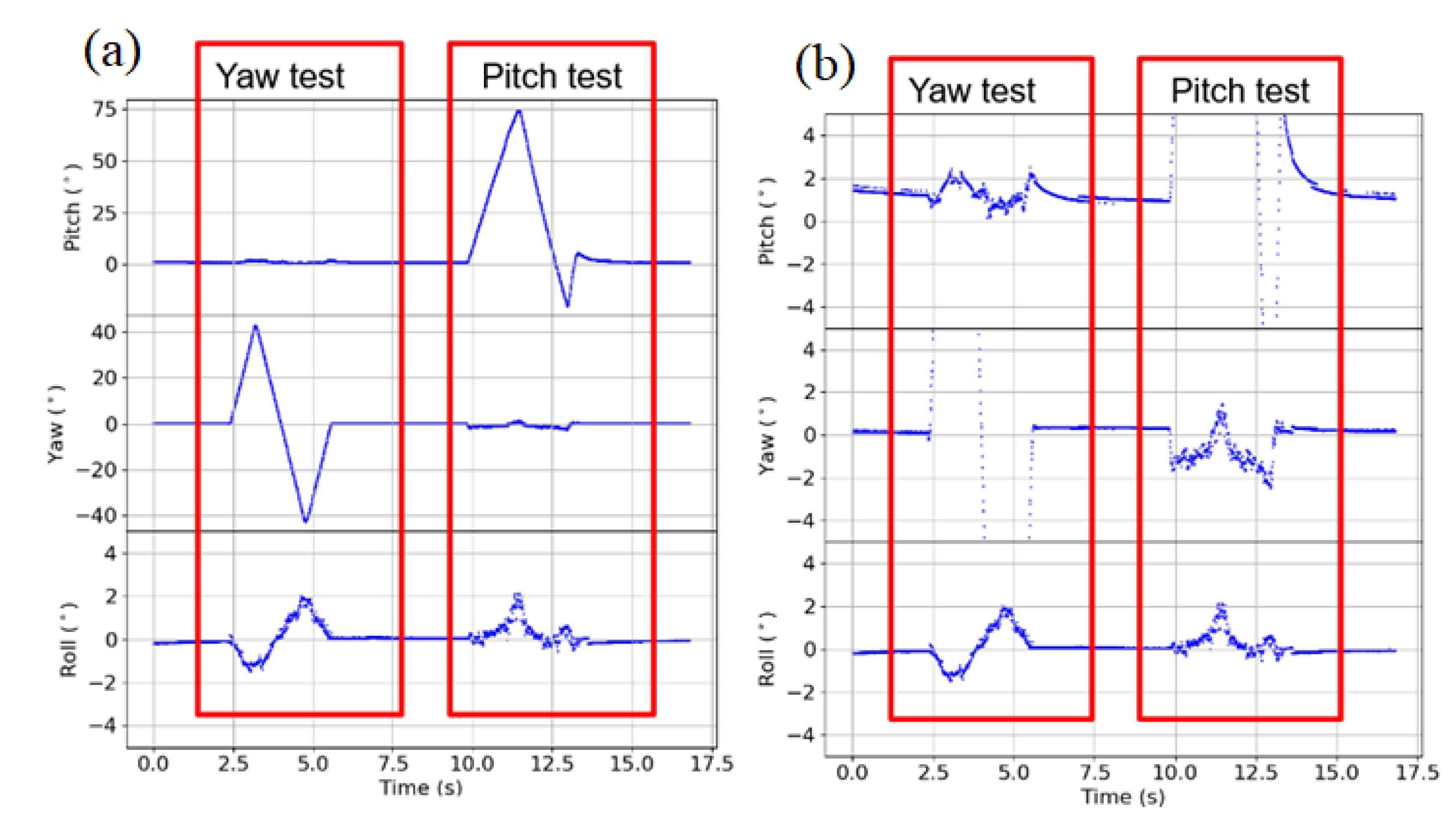
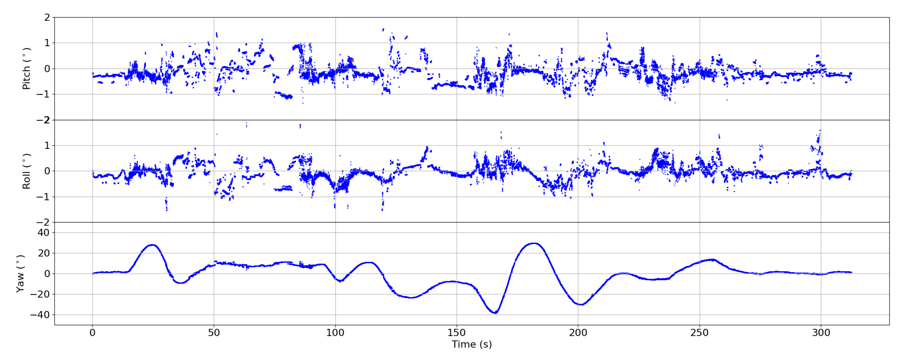
As there was no defined case study to prove the proposed concept and the relative position controller was not implemented for the flight, flight tests were conducted only with individual UAVs to explore the achievable performance of a single UAV in the concept. This can help to avoid impractical requirements defined for the system. Although the UAV (DJI M600) drifts up to a maximum of 50 cm from the set point under extreme wind gusts, this drift still remains small with an order of 10 cm over short time span. This implies that it is possible to have precise position control over small time scales. The same is applicable to the UAV attitudes which remain below 7° even with wind gusts up to 8 m/s. The gimbal system was shown to keep a steady attitude around the set point even under motion of the mockup. Only when the mockup makes drastic yaw changes of up to 30°, the roll and pitch axes of the gimbal move up to a maximum of 1°. During flight, however, the yaw axis of the UAV was found to be relatively stable around the set point, varying less than 1°. It can be concluded that, even in combination with the relatively good position control of the RTK based DJI M600, the accuracy requirements mentioned in Figure 1 cannot be met with the existing system. Since the yaw is relatively fixed, the two UAVs should be positioned in such a way that they are facing towards each other. Then the plane perpendicular to the yaw axis of each UAV would remain relatively fixed with respect to each other. Any relative motion along the yaw axis is therefore not as bad for the sensor pointing as the motion along roll and pitch axes. This result also has implications on the relative position controller design since relative position accuracy requirements for Y (lateral motion) and Z (vertical motion) are more stringent compared to X (forward motion). Moreover, the UAV vertical movement shows much less drift even under wind disturbances. One limitation with the current gimbal system, however, is the inaccessible control system. Access to the control system would allow to control the relative attitude of the two UAVs within the proposed limits of within 0.3° when combined with RTK based position estimation and a dual quaternion-based control of both UAVs.
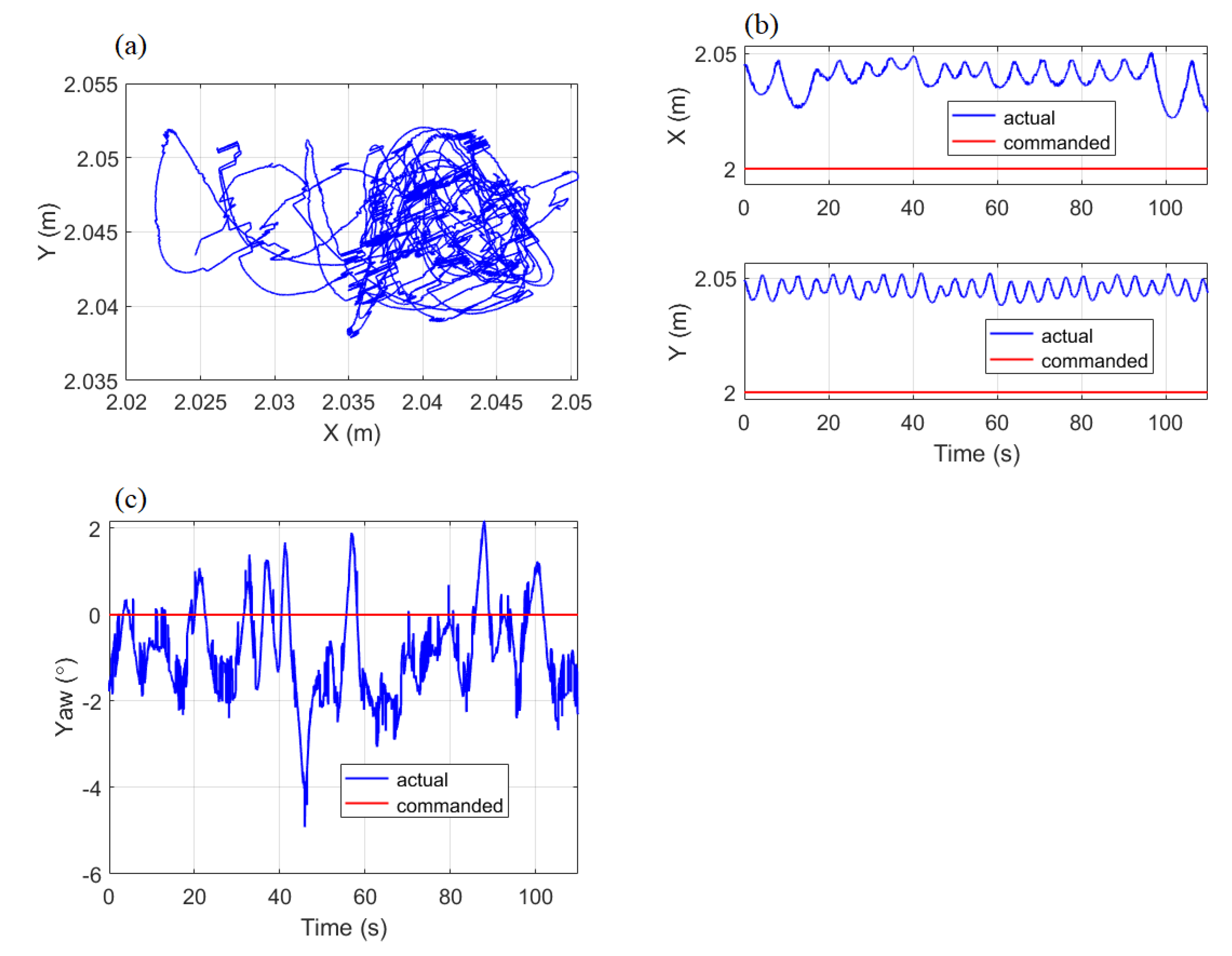
The ELISSA lab was used to evaluate the performance of dual quaternion-based SMC. In experiments, a control accuracy of 2–5 cm was achieved for the position control. It is promising to use SMC for the relative position control in the proposed formation flying. A wind disturbance model was extracted based on tracking the measured flight trajectory of UAVs. In spite of the simplicity of the disturbance extraction method, it allows to preliminarily evaluate the performance of the SMC controller under wind disturbances in ELISSA.
In future works, a complete dual mockup setup with gimbal stabilized optical measurement system would be created and experimented first on ELISSA. Upon successful evaluation on the ELISSA, two UAVs would be prepared along with an implementation of the dual quaternion-based SMC for real UAV flights. This setup would be used to validate the proposed formation flying-based concept of optical measurement in outdoor flights.

Author Contributions

Conceptualization, M.K.B.-L., A.L. and U.B.; methodology, Y.K., J.B., J.Y. and M.K.B.-L.;software, J.B., Y.K. and J.Y.; validation, J.Y., Y.K. and M.K.B.-L.; formal analysis, J.Y. and Y.K.; investigation, J.Y. and Y.K.; resources, A.L., U.B. and E.S.; data curation, J.Y. and Y.K.; writing—original draft preparation, J.Y., Y.K. and M.K.B.-L.; writing—review and editing, J.Y., Y.K., M.K.B.-L., J.B., A.L., U.B. and E.S.; visualization, J.Y. and Y.K.; supervision, A.L., U.B., M.K.B.-L.; and E.S.; project administration, J.Y. and Y.K.; funding acquisition, A.L., U.B., M.K.B.-L. and E.S. All authors have read and agreed to the published version of the manuscript.

Funding

This research was funded by Technische Universität Braunschweig under the Funding Program “12plus6”. The program provides funding to encourage research proposals to the German Research Foundation to answer fundamental research questions. The article processing charge (APC) was funded by the German Research Foundation and the Open Access Publication Funds of Technische Universität Braunschweig.

Data Availability Statement

The data presented in this study are available on request from the corresponding author.

Acknowledgments

The authors acknowledge the help provided by Karl-Rainer Wilke, Bernard Leugers, and Lasse Maywald for their support during experiments on the ELISSA testbed.

Conflicts of Interest

The authors declare no conflict of interest.

References

  1. Konrad, T.; Hill, M.; Rowland, J.M.J. A small, radio-controlled aircraft as a platform for meteorological sensors. Appl. Phys. Lab. Tech. Dig. 1970, 10, 11–19. [Google Scholar]
  2. van den Kroonenberg, A.; Martin, T.; Buschmann, M.; Bange, J.; Vörsmann, P. Measuring the wind vector using the autonomous mini aerial vehicle M2AV. J. Atmos. Ocean. Technol. 2008, 25, 1969–1982. [Google Scholar] [CrossRef]
  3. Lampert, A.; Pätzold, F.; Jiménez, M.A.; Lobitz, L.; Martin, S.; Lohmann, G.; Canut, G.; Legain, D.; Bange, J.; Martínez-Villagrasa, D.; et al. A study of local turbulence and anisotropy during the afternoon and evening transition with an unmanned aerial system and mesoscale simulation. Atmos. Chem. Phys. 2016, 16, 8009–8021. [Google Scholar] [CrossRef] [Green Version]
  4. Martin, S.; Bange, J.; Beyrich, F. Meteorological profiling of the lower troposphere using the research UAV “M2AV Carolo”. Atmos. Meas. Tech. 2011, 4, 705–716. [Google Scholar] [CrossRef] [Green Version]
  5. Jonassen, M.O.; Tisler, P.; Altstädter, B.; Scholtz, A.; Vihma, T.; Lampert, A.; König-Langlo, G.; Lüpkes, C. Application of remotely piloted aircraft systems in observing the atmospheric boundary layer over Antarctic sea ice in winter. Polar Res. 2015, 34, 25651. [Google Scholar] [CrossRef] [Green Version]
  6. Lampert, A.; Pätzold, F.; Asmussen, M.O.; Lobitz, L.; Krüger, T.; Rausch, T.; Sachs, T.; Wille, C.; Sotomayor Zakharov, D.; Gaus, D.; et al. Studying boundary layer methane isotopy and vertical mixing processes at a rewetted peatland site using an unmanned aircraft system. Atmos. Meas. Tech. 2020, 13, 1937–1952. [Google Scholar] [CrossRef] [Green Version]
  7. Bärfuss, K.; Pätzold, F.; Altstädter, B.; Kathe, E.; Nowak, S.; Bretschneider, L.; Bestmann, U.; Lampert, A. New setup of the UAS ALADINA for measuring boundary layer properties, atmospheric particles and solar radiation. Atmosphere 2018, 9, 28. [Google Scholar] [CrossRef] [Green Version]
  8. Brosy, C.; Krampf, K.; Zeeman, M.; Wolf, B.; Junkermann, W.; Schäfer, K.; Emeis, S.; Kunstmann, H. Simultaneous multicopter-based air sampling and sensing of meteorological variables. Atmos. Meas. Tech. 2017, 10, 2773–2784. [Google Scholar] [CrossRef] [Green Version]
  9. Andersen, T.; Scheeren, B.; Peters, W.; Chen, H. A UAV-based active AirCore system for measurements of greenhouse gases. Atmos. Meas. Tech. 2018, 11, 2683–2699. [Google Scholar] [CrossRef] [Green Version]
  10. Bates, T.S.; Quinn, P.K.; Johnson, J.E.; Corless, A.; Brechtel, F.J.; Stalin, S.E.; Meinig, C.; Burkhart, J.F. Measurements of atmospheric aerosol vertical distributions above Svalbard, Norway, using unmanned aerial systems (UAS). Atmos. Meas. Tech. 2013, 6, 2115–2120. [Google Scholar] [CrossRef] [Green Version]
  11. Altstädter, B.; Platis, A.; Wehner, B.; Scholtz, A.; Wildmann, N.; Hermann, M.; Käthner, R.; Baars, H.; Bange, J.; Lampert, A. ALADINA—An unmanned research aircraft for observing vertical and horizontal distributions of ultrafine particles within the atmospheric boundary layer. Atmos. Meas. Tech. 2015, 8, 1627–1639. [Google Scholar] [CrossRef] [Green Version]
  12. Platis, A.; Altstädter, B.; Wehner, B.; Wildmann, N.; Lampert, A.; Hermann, M.; Birmili, W.; Bange, J. An observational case study on the influence of atmospheric boundary-layer dynamics on new particle formation. Bound. Layer Meteorol. 2016, 158, 67–92. [Google Scholar] [CrossRef]
  13. Telg, H.; Murphy, D.M.; Bates, T.S.; Johnson, J.E.; Quinn, P.K.; Giardi, F.; Gao, R.S. A practical set of miniaturized instruments for vertical profiling of aerosol physical properties. Aerosol Sci. Technol. 2017, 51, 715–723. [Google Scholar] [CrossRef]
  14. Emeis, S.; Kalthoff, N.; Adler, B.; Pardyjak, E.; Paci, A.; Junkermann, W. High-resolution observations of transport and exchange processes in mountainous terrain. Atmosphere 2018, 9, 457. [Google Scholar] [CrossRef] [Green Version]
  15. Lampert, A.; Altstädter, B.; Bärfuss, K.; Bretschneider, L.; Sandgaard, J.; Michaelis, J.; Lobitz, L.; Asmussen, M.; Damm, E.; Käthner, R.; et al. Unmanned aerial systems for investigating the polar atmospheric boundary layer—Technical challenges and examples of applications. Atmosphere 2020, 11, 416. [Google Scholar] [CrossRef] [Green Version]
  16. DeBruyn, Z.J.; Wagner-Riddle, C.; VanderZaag, A. Assessment of open-path spectrometer accuracy at low path-integrated methane concentrations. Atmosphere 2020, 11, 184. [Google Scholar] [CrossRef] [Green Version]
  17. Rekleitis, I.M.; Babin, P.; DePriest, A.; Das, S.; Falardeau, O.; Dugas, O.; Giguère, P. Experiments in Quadrotor Formation Flying Using On-Board Relative Localization. 2015. Available online: http://www2.ift.ulaval.ca/~pgiguere/papers/ARdroneCL_Workshop.2015.pdf (accessed on 1 July 2021).
  18. Achtelik, M.W.; Weiss, S.; Chli, M.; Dellaerty, F.; Siegwart, R. Collaborative stereo. In Proceedings of the 2011 IEEE/RSJ International Conference on Intelligent Robots and Systems, San Francisco, CA, USA, 25–30 September 2011; pp. 2242–2248. [Google Scholar]
  19. Holter, S.; Tsoukalas, A.; Evangeliou, N.; Giakoumidis, N.; Tzes, A. Relative visual localization for unmanned aerial systems. arXiv 2020, arXiv:cs.RO/2003.01954. [Google Scholar]
  20. Rafifandi, R.; Asri, D.L.; Ekawati, E.; Budi, E.M. Leader–follower formation control of two quadrotor UAVs. SN Appl. Sci. 2019, 1. [Google Scholar] [CrossRef] [Green Version]
  21. Dahlin Rodin, C.; de Alcantara Andrade, F.A.; Hovenburg, A.R.; Johansen, T.A. A survey of practical design considerations of optical imaging stabilization systems for small unmanned aerial systems. Sensors 2019, 19, 4800. [Google Scholar] [CrossRef] [Green Version]
  22. Gašparović, M.; Jurjević, L. Gimbal influence on the stability of exterior orientation parameters of UAV acquired images. Sensors 2017, 17, 401. [Google Scholar] [CrossRef] [Green Version]
  23. Team, P.A. PX4 Flight Review Log Analysis Library. 2016–2021. Available online: https://github.com/PX4/flight_review (accessed on 1 July 2021).
  24. CoreFlow. SmartNozzle. 2021. Available online: https://www.coreflow.com/technology/smartnozzle (accessed on 6 May 2021).
  25. OptiTrack. OptiTrack. 2021. Available online: https://optitrack.com/ (accessed on 6 May 2021).
  26. Yang, J.; Stoll, E. Adaptive sliding mode control for spacecraft proximity operations based on dual quaternions. J. Guid. Control Dyn. 2019, 42, 2356–2368. [Google Scholar] [CrossRef]
  27. Waslander, S.; Wang, C. Wind disturbance estimation and rejection for quadrotor position control. In AIAA Infotech@Aerospace Conference; AIAA: Seattle, WA, USA, 9 April 2009; Chapter Session: I@A-47; pp. 1–14. [Google Scholar]
  28. Schiano, F.; Alonso-Mora, J.; Rudin, K.; Beardsley, P.; Siegwart, R.; Siciliano, B. Towards estimation and correction of wind effects on a quadrotor UAV. In Proceedings of the IMAV 2014: Proceedings of the International Micro Air Vehicle Conference and Competition, Delft, The Netherlands, 12–15 August 2014; pp. 134–141. [Google Scholar]
  29. Byun, J.; Mäkiharju, S.A.; Mueller, M.W. A flow disturbance estimation and rejection strategy for multirotors with round-trip trajectories. arXiv 2021, arXiv:cs.RO/2003.02974. [Google Scholar]
  30. Seher-Weiss, S.; von Grünhagen, W. Development of EC 135 turbulence models via system identification. Aerosp. Sci. Technol. 2012, 23, 43–52. [Google Scholar] [CrossRef]
  31. González-Rocha, J.; De Wekker, S.F.J.; Ross, S.D.; Woolsey, C.A. Wind profiling in the lower atmosphere from wind-induced perturbations to multirotor UAS. Sensors 2020, 20, 1341. [Google Scholar] [CrossRef] [PubMed] [Green Version]
  32. Simma, M.; Mjøen, H.; Boström, T. Measuring wind speed using the internal stabilization system of a quadrotor drone. Drones 2020, 4, 23. [Google Scholar] [CrossRef]
  33. Wang, J.Y.; Luo, B.; Zeng, M.; Meng, Q.H. A wind estimation method with an unmanned rotorcraft for environmental monitoring tasks. Sensors 2018, 18, 4504. [Google Scholar] [CrossRef] [PubMed] [Green Version]
  34. Slotine, J.J.; Coetsee, J. Adaptive sliding controller synthesis for non-linear systems. Int. J. Control 1986, 43, 1631–1651. [Google Scholar] [CrossRef]
Figure 1. Optical measurement concept and the related marker tracking pointing requirement for distributed sensor system.
Atmosphere 12 00874 g001
Figure 2. Engineering concept of formation flying UAVs for a distributed system for optical measurements.
Atmosphere 12 00874 g002
Figure 3. UAVs used for experimentation. (a) DJI Matrice M600. (b) Tarot X4.
Atmosphere 12 00874 g003
Figure 4. ELISSA testbed with control station, air-bearing table, cameras, and blowers.
Atmosphere 12 00874 g004
Figure 5. The mockup with a glass plate on the air-bearing table.
Atmosphere 12 00874 g005
Figure 6. Position drift over time for DJI M600 with (a) GNSS and (b) RTK-GNSS. The experiment was conducted on 23 February 2021.
Atmosphere 12 00874 g006
Figure 7. Comparison of DJI M600 movements.
Atmosphere 12 00874 g007
Figure 8. Comparison of DJI M600 velocities.
Atmosphere 12 00874 g008
Figure 9. Comparison of DJI M600 angular rates.
Atmosphere 12 00874 g009
Figure 10. Comparison of DJI M600 attitude.
Atmosphere 12 00874 g010
Figure 11. RMSE comparison between wind-still and windy conditions for DJI M600. All values are with respect to a set point. (a) RMSE on position. (b) RMSE on velocity. (c) RMSE on attitude. (d) RMSE on angular velocity.
Atmosphere 12 00874 g011
Figure 12. RMSE comparison between wind-still and windy conditions for Tarot X4. All values are with respect to a set point. (a) RMSE on position. (b) RMSE on velocity. (c) RMSE on attitude. (d) RMSE on angular velocity.
Atmosphere 12 00874 g012
Figure 13. Results of regulation control using SMC. (a) Position trajectory in XY plane. (b) Time history of actual and commanded positions. (c) Time history of actual and commanded yaw angles.
Atmosphere 12 00874 g013
Figure 14. Results of reference trajectory tracking. (a) Time history of X. (b) Time history of Y.
Atmosphere 12 00874 g014
Figure 15. Recorded control commands.
Atmosphere 12 00874 g015
Figure 16. Gimbal setup.
Atmosphere 12 00874 g016
Figure 17. Gimbal axis coupling quantification tests. (a) Normal view. (b) Zoomed-in view.
Atmosphere 12 00874 g017
Figure 18. Attitude during trajectory following tests.
Atmosphere 12 00874 g018
Table 1. Salient specifications of the UAV systems used for the flight experimentation.
ParameterDJI M600 ProTarot 450 mm
FrameHexacopterQuadcopter
MTOW (kg)142.5
Position Sensors3× GNSS, IMU, D-RTK1× GNSS, 3× IMU, RTK
Payload Weight (kg)50.5
Table 2. Wind levels recorded during the flight experiments.
Wind LevelWind Speed Range
Level 10–2 m/s
Level 22–5 m/s
Level 35–8 m/s
Publisher’s Note: MDPI stays neutral with regard to jurisdictional claims in published maps and institutional affiliations.

