
Tailored Pre-Lithiation Using Melt-Deposited Lithium Thin Films
by
 ,
,
Kay Schönherr
1,*,
Markus Pöthe
1,
Benjamin Schumm
1,*,
Holger Althues
1,
Christoph Leyens
1,2 and
Stefan Kaskel
1,3 1
Chemical Surface and Battery Technology, Fraunhofer Institute for Material and Beam Technology IWS, Winterbergstaße 28, 01237 Dresden, Germany
2
Institute of Materials Sience, Technische Universität Dresden, Helmholtzstraße 7, 01069 Dresden, Germany
3
Inorganic Chemistry I, Technische Universität Dresden, Helmholtzstraße 10, 01069 Dresden, Germany
*
Authors to whom correspondence should be addressed.
Batteries 2023, 9(1), 53; https://0-doi-org.brum.beds.ac.uk/10.3390/batteries9010053
Submission received: 15 November 2022
/
Revised: 3 January 2023
/
Accepted: 9 January 2023
/
Published: 12 January 2023
(This article belongs to the Special Issue Feature Papers to Celebrate the First Impact Factor of Batteries)
Abstract
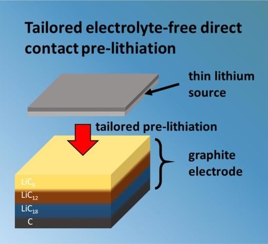
:The user demands lithium-ion batteries in mobile applications, and electric vehicles request steady improvement in terms of capacity and cycle life. This study shows one way to compensate for capacity losses due to SEI formation during the first cycles. A fast and simple approach of electrolyte-free direct-contact pre-lithiation leads to targeted degrees of pre-lithiation for graphite electrodes. It uses tailor-made lithium thin films with 1–5 µm lithium films produced by lithium melt deposition as a lithium source. These pre-lithiated graphite electrodes show 6.5% capacity increase after the first cycles in NCM full cells. In this study, the influence of the pre-lithiation parameters—applied pressure, temperature and pressing time—on the pre-lithiation process is examined.
1. Introduction
Lithium-ion batteries are of common use for electric vehicles (EVs) today. However, the capacity of these batteries is limited and so is the EV range [1]. One way to further increase the LIBs capacity can be increasing the cathode capacity utilization. State-of-the-art lithium-ion batteries are built in an uncharged state. As a result, all of the lithium available for the cell chemistry is included in the cathode. By charging, the lithium is transferred to the anode, which is graphite in most cases. During the formation, the deposited lithium diffuses into the anode film and reacts with the electrolyte and graphite surface in order to form the SEI [2,3]. This results in a low initial columbic efficiency (ICE) of about 90% for graphite anodes and, as a consequence, 10% capacity loss. This means 10% of today’s EV battery capacity is not accessible [4]. For silicon-based electrodes, the effect is even more dramatic. Here, the first cycle efficiency is about 50–80%, which leads to even higher irreversible capacity losses of 20 to 50% [5,6]. By compensating for these losses, the usable capacity of EV batteries could be increased by 10% to 50% by using the complete cathode capacity, resulting in a range extension of 40–60 km for these cars [7].
Pre-lithiation is one way to increase the usable capacity by compensating the lithium losses during the SEI formation. Here, additional lithium is introduced into the cell. The cell starts with more than 100% of lithium content regarding the cathode capacity after cell assembly with the goal to be at 100% lithium content after the formation of the cell is done, and the SEI is stabilized and completely formed.
Pre-lithiation can be performed on the cathode and on the anode sides. There are two routes of cathode pre-lithiation described in the literature [8]. One way is adding additives to the cathode material during the manufacturing of the cathode electrode [9,10,11,12,13,14]. These additives have to be chemically, electrochemically and thermally stable, and need to fit the cathode-processing conditions. Over-lithiated cathode materials, where cathode materials are chemically over-saturated with lithium during material manufacturing or electrochemically after electrode processing are a second way of cathode pre-lithiation [15,16,17,18,19,20,21].
An alternative strategy is the pre-lithiation of the anode. Here, according to the predicted lithium loss, a specific amount of lithium is added to the anode material and can compensate for the losses upon the formation cycles. There are several approaches for anode pre-lithiation described in literature, focusing on graphite, silicon, lithium-titanate (LTO) electrodes and even on lithium-ion capacitors (LiC) [22,23].
Pre-lithiation can be carried out chemically by adding lithium-containing chemicals or solvents to the anode material mixture during anode manufacturing [24,25,26]. This allows good control over the degree of pre-lithiation. However, the reaction time is long, and the used chemicals are often problematic. Possibly formed side products have to be removed afterwards [24,25,26].
Alternatively, the thermal evaporation of lithium onto the anode can be used for pre-lithiation [27,28]. This method can produce highly controlled pre-lithiation. However, the apparatus effort for thermal lithium evaporation is comparably high due to the process taking place in a low-pressure environment, and the lithium yield is rather low due to material deposition everywhere inside the deposition chamber of the apparatus [27,28].
The pre-lithiation can also be achieved with an electrochemical strategy [29,30,31,32]. Within this two-step procedure, the anode is built in a first intermediate cell with lithium metal as a counter electrode. By applying a current, the pre-lithiation is observed. Subsequently, this intermediate pre-lithiation cell has to be disassembled for obtaining the pre-lithiated electrode for the second step of LIB cell manufacturing. The degree of pre-lithiation can be controlled quite well with this method, but the implementation into the battery manufacturing line is challenging, due to the high complexity and low speed of this approach [29,30,31,32].
As another potential candidate, pre-lithiation can be realized by the direct contact of the anode material with metallic lithium. Therefore, lithium can be used either in powder form or as a lithium foil. A commonly used method is the application of so-called stabilized lithium metal powders (SLMPs) in a mixture with anode materials [33,34,35,36,37,38,39,40,41,42,43]. Through the application of pressure and electrolytes, the lithium intercalates into the anode material. This is a rather feasible way of controlling the degree of pre-lithiation. However, residues from the lithium passivation remain in the anode and cannot be addressed electrochemically. In addition, the use of solvents and other reagents to crack the surface cover of the SLMP needs additional washing/drying steps [33,34,35,36,37,38,39,40,41,42,43].
As a commonly used method for the pre-lithiation of many materials, lithium foil was applied in direct contact with the anode sheet [44,45,46,47,48]. Not only graphite, but also silicon, LTO and other anode materials, are under evaluation for the “direct contact pre-lithiation” procedure. This method seems to be quite handy since it only involves pressing the lithium foil onto the surface of the anode. Pre-lithiation happens quite fast, and the procedure could be easily implemented into existing lithium-ion battery production lines. However, due to the use of quite thick lithium foils, the pre-lithiation degree is difficult to control. In addition, the remaining lithium foil with the unutilized lithium has to be removed after the process. However, this causes difficulties in most cases due to the strong adhesion between the remaining lithium foil and the pre-lithiated anode surface.
Thin lithium foils providing exactly the amount of lithium required to compensate for the initial lithium losses could make the control of the degree of pre-lithiation much easier. For a typical graphite anode ~3 µm and for silicon-based anodes between ~6 µm and ~15 µm, lithium would be sufficient [49]. However, lithium foils produced by roll pressing are much thicker (>30 µm) or available only in small dimensions [50]. Lithium thin films made by vapor deposition techniques are thin enough but very costly to produce [51]. For that reason, a study was performed to use lithium foils in different shapes and sizes to compensate for the high lithium foil thickness by decreased area of the used lithium foil pieces [49]. However, whether the lithium distribution is homogeneous throughout the electrode material in this approach is questionable.
Many of the described pre-lithiation techniques and methods show a good way to control the degree of pre-lithiation, but the needed effort is high, or the pre-lithiation is very time-consuming. On the other hand, some techniques are faster and could maybe be well integrated into existing production lines but struggle with the control of the degree of pre-lithiation.
Within this publication, we introduce a method for direct contact pre-lithiation with controlled degree of pre-lithiation by applying a method of melt deposition of lithium thin films in the range of 1–30 µm (Figure 1a) [52,53]. Good control over the pre-lithiation degree on the one hand and fast pre-lithiation with a straightforward perspective of process integration on the other hand can be realized using the thin lithium films on temporary substrates for contact-based pre-lithiation. The combination of these techniques enables the commercial use of pre-lithiation for the capacity extension of existing lithium-ion batteries.
2. Materials and Methods
2.1. Lithium Melt Deposition
Lithium metal melts at a relatively low temperature (180.5 °C) [54]. This enables the use of standard liquid coating techniques with relatively low apparatus effort, e.g., doctor blading, dip coating and spray coating. Due to its high reactivity especially in the molten state, an argon atmosphere is mandatory. Like many other metal melts, liquid lithium also shows a high surface energy, leading to low wettability on most substrate surfaces [55]. Lithiophilic interlayers can be applied to enhance the wettability. It is possible to apply alloy-forming species, such as silicon or tin or metal oxide layers [56,57,58,59,60]. In this work, we used a highly effective approach to form a nickel oxide layer on top of nickel foil by heating in air atmosphere [52,53]. This layer increases the wettability of the nickel foil dramatically due to the conversion reaction of NiO with Li, which decreases the surface energy:
NiO + 2 Li → Ni + Li2O
Substrates prepared this way can be coated with liquid lithium by a dip-coating-inspired process using a roll-to-roll equipment (Figure 1b). The resulting lithium loading can be adjusted in a range of 0.05 mg cm−2 and 1.5 mg cm−2 (~1 µm and ~30 μm respectively with a theoretical density of 0.534 g cm−3) by adjusting the web speed (Figure 1c). With a coating width of up to 100 mm on 150 mm wide substrates, it is possible to provide thin lithium metal coatings on a roll. More information on the melt deposition process can be found in Supplementary Figures S1 and S2. For this study, single-side lithium coated nickel foil was used as a temporary substrate. By adjusting the lithium layer thickness to the amount of lithium to be compensated, the targeted degree of pre-lithiation can be well-controlled. It is important to have a mechanically stable substrate since it has to be removed after direct contact pre-lithiation. We used a 25 µm thick nickel foil (hpulcas) with excellent mechanical stability due to its grain structure combined with the high purity and low carbon and sulfur content (Ni: ≥99.98%) [61]. In principle, the nickel foil can be reused after the pre-lithiation process once it is scaled up to a roll-to-roll process.
The lithium films were deposited using the Fraunhofer IWS lithium melt deposition process (described elsewhere [52]) on a 25 µm thick nickel foil (Ni: ≥99.98%, hpulcas [61]), which was treated in a roll-to-roll furnace at 600 °C for 240 s in laboratory air atmosphere using a roll-to-roll (R2R) furnace (HTM Reetz). As a result of this thermal treatment, a ~200 nm thin NiO layer was formed. The thus treated nickel foil substrate (width: 110 mm, length: 10 m) was coated with molten lithium (purity: 99.95%, Cellithium) using a liquid lithium coating setup (described above) with a vessel temperature of 210 °C under an argon atmosphere inside a glove box with <0.1 ppm H2O, <0.1 ppm O2, and <10 ppm N2. The substrate velocity was varied between 50 and 320 mm min−1 by a R2R winding to form the needed lithium thicknesses between 2 and 15 µm. The lithium coating parameters and the resulting lithium loadings are shown in Table 1. The sheets were punch cut in the described dimensions after lithium coating. Each sheet was weighed to determine the lithium loading. In addition, electrochemical stripping experiments were performed for the same reason.
2.2. Electrolyte-Free Direct Contact Pre-Lithiation
With the temporary lithium substrates, we performed electrolyte-free direct contact pre-lithiation. For this purpose, commercially available graphite electrodes (3.45 mAh cm−2, 70 µm graphite on 10 µm copper foil, 46 mm × 71 mm) were stacked on the temporary lithium substrates in a specially designed pressing tool (Figure 1c,d) [62]. Electrolyte-free contact lithiation is based on the process of intercalation of lithium in between the graphite layers due to different redox potentials:
Li + 6 C → LiC6
Increased pressure and temperature promote the intercalation, whereby pre-lithiation of the graphite can take place. In order to increase the temperature and pressure on the samples, they were transferred to a hot press. The essential task of the pressing tool is to protect the samples from the laboratory atmosphere, especially from oxygen, nitrogen and humidity. Furthermore, the device enables both the force and the heat transfer to the sample. By varying the parameters temperature, pressure and time, we carried out electrolyte-free contact lithiation, resulting in a color change of the graphite electrodes from grey-black (before) to bluish, reddish and golden (after pre-lithiation). According to Shellikeri et al. this indicates a successful intercalation of Li+ ions into the graphite lattice [63]. Electrochemical stripping experiments and galvanostatic cycling in coin cells allowed the quantification of the degree of pre-lithiation. The CE (coulomb efficiency) of the first cycle was determined as a reference value and compared with samples without pre-lithiation. A successful pre-lithiation is indicated by a higher first cycle CE, due to a lower or even compensated lithium loss upon SEI formation.
After the temporary substrates had been manufactured, the pre-lithiation was carried out. For this purpose, the graphite electrode (Evonik, 3.45 mAh cm−2) and the temporary lithium substrate were stacked on top of each other in the upper part of the pressing tool. A Mylar-foil was used to prevent the samples from sticking to the pressing tool. The lower part was then inserted and locked. After that, the pressing tool was transferred to the hydraulic press. The heating was set to the desired temperature and held for a period of 30 min to ensure that the samples and the material of the pressing tool are at the desired temperature. After that, the experiment started by setting the aimed pressure and holding for the desired duration. After pre-lithiation, the pressing tool was transferred to the glovebox again, where the samples were removed. Table 2 shows the used parameters for the different studies. One parameter was varied, while the other two were kept constant.
2.3. Electrochemical Characterization
To determine the amount of lithium on the temporary substrates, stripping tests (0.079 mA cm−2, 2.5 V cut-off voltage) were carried out. The resulting capacity correlates to the amount of the deposited lithium.
To prove the positive influence of the pre-lithiation, the samples were tested electrochemically. Therefore, the pre-lithiated graphite electrodes were tested in half cells where the graphite was fully lithiated and then stripped electrochemically to calculate the ICE. These cells were assembled vs. lithium foil (diameter: 16.5 mm, thickness: 250 µm, purity: 99.9%, MTI Corporation, Richmond, CA, USA). For that reason, circular electrodes were punched out (diameter: 10 mm) and placed in a CR2016 coin cell (MTI Corp.) with a separator sandwich consisting of two PE separators (thickness: 12 µm) and one glass fiber separator (thickness: 260 µm). Then, 100 µL 1 M LiPF6 in ethylene carbonate/dimethyl carbonate (EC/DME) (1:1) was used as an electrolyte. The high amount of electrolyte and the thick separators were applied to guarantee full utilization of the pre-lithiated lithium. With both the unlithiated and pre-lithiated graphite electrodes, galvanostatic charge/discharge measurements were carried out. They were cycled (5×) with a constant current (0.1 C) in a voltage range of 5 mV and 1.5 V.
To investigate the performance of the pre-lithiated cells, subsequently, full cells were prepared to evaluate the performance under more realistic conditions. Here, the cells were fully charged and discharged to determine the initial CE. The cell setup did not differ in comparison to the half cells, except the cathode. In this case, an NCM-811-cathode (2 mAh cm−2; Custom Cells GmbH, Itzehoe, Germany) was used. The NCM811/Gr full cells were cycled within the potential range of 4.2 to 2.2 V. For the formation cycles, 0.1, 0.2 C were applied for two cycles of each until 10% of the current was reached. For both charge and discharge, a constant voltage step (CVS) was performed. The cells were then cycled at the C rate of 1 C further to obtain long life stability.
All cells were assembled in a glove box, filled with argon (Mbraun, 0.1 ppm O2 and H2O) and tested in a BaSyTec Cell Test System (BaSyTec GmbH, Asselfingen, Germany). The temperature was at 21 ± 1 °C.
3. Results and Discussion
For determining the irreversible capacity loss of lithium-ion batteries, NCM full cells with graphite electrodes were evaluated in galvanostatic cycling experiments in coin cells. After the first cycle, an average loss of 12% was determined (Figure 2a). This can be equivalent to a lithium loss of 0.082 mg cm−2 due to SEI formation, but also due to other side reactions, such as cathode passivation, etc. To identify the anode capacity loss due to SEI formation, in addition, the graphite anodes were evaluated in coin cells (half cells vs. Li). Here, an average loss of 7% after the first cycle was determined, corresponding to an irreversible loss of lithium of 0.063 mg cm−2 (Figure 2d).
To compensate for this irreversible lithium loss, the method of electrolyte-free direct contact pre-lithiation was used. For this purpose, temporary substrate carriers were prepared with an average lithium loading of 0.2 mg cm−2 (Figure 1e). Pre-lithiation provides this additional amount of lithium to the graphite electrode, which can be used for SEI formation. To confirm the success of this experiment, pre-lithiated electrodes were electrochemically stripped in half cells to determine the excess amount of lithium in the graphite electrode. As expected, the stripped amount of lithium was very low. Only 0.16 mAh cm−2 were measured. This corresponds to a lithium amount of 0.04 mg cm−2. The here measured capacity results from excess lithium, which was not consumed by SEI formation or other side reactions. Thus, it can be assumed that the additional lithium introduced by the temporary substrates was sufficient to compensate for the irreversible capacity losses due to SEI formation. The Coulomb efficiency (CE) gives an indication of the success of the pre-lithiation. The lower the irreversible loss of capacity, the higher the initial Coulomb efficiency (ICE), which is a sign of successful pre-lithiation. Lowered initial voltage also indicates the presence of lithium inside the graphite electrode. In these experiments, lithium was transferred into the graphite electrode electrochemically. If there was no lithium in the graphite electrode before (unlithiated state), the measured charge capacity consists of the graphite capacity (3.45 mAh cm−2) plus the lithium consumption due to SEI formation (0.27 mAh cm−2). In the discharge step, only the graphite capacity can be transferred because the SEI stays stable. The resulting ICE is lowered. If pre-lithiated graphite is used, the measured charge capacity is lowered by the amount of lithium already inside the electrode. If the pre-lithiated lithium amount is exactly the amount of the lithium used for SEI formation, the discharge capacity is exactly the charge capacity, and the ICE is 100% as it was the target of this study. In half cells with pre-lithiated graphite electrodes, an ICE of 99.91% was reached with optimal pre-lithiation parameters (Figure 2i). Voltage profiles can be found in Supplementary Figure S4.
The same pre-lithiated material was tested in full cells, too. This cell reached a capacity of 2.46 mAh cm−2 in the first discharge (Figure 2b) while the unlithiated cell only showed 2.31 mAh cm−2 (Figure 2a). This calculates to an increase in usable capacity of 6%. Even after five formation cycles, the capacity was increased by 6.5% in total usable capacity (Figure 2c). The initial capacity loss in NCM full cells was reduced from 12% to 5.5% by pre-lithiating the graphite electrode. The remaining capacity loss could result from other side reactions also on cathode side and cannot be compensated by introducing additional lithium into the system.
In a parameter study, we evaluated the influence of applied pressure, pressing time and temperature during the pre-lithiation step on the cycle efficiency of the graphite electrodes. The pre-lithiated material was built into coin-cell-sized half cells and was cycled electrochemically afterwards.
The first varied parameter was the applied pressure. It varied between 5 and 40 MPa, while temperature (150 °C) and time (15 min) were constant. It seems to have a very high impact on the pre-lithiation success (Figure 2f). Obviously, higher pressure (>35 MPa) leads to better pre-lithiation (99.9% for 40 MPa) due to a better contact of the lithium–graphite interface and therefore, better lithium transport from the temporary substrate into the graphite electrode. In our setup, the pressure could not be increased further than 40 MPa, although a further increase could have a positive influence on the pre-lithiation.
The time is an important parameter for transport processes, especially when it comes to continuous large-scale production lines since the throughput is one key factor. In this study, the time was varied from 0 to 120 min, with pressure (20 MPa) and temperature (150 °C) being fixed. No significant influence of the time on the pre-lithiation was measurable (Figure 2g). Short pressuring durations as well as long durations did not lead to a sufficient pre-lithiation. Obviously, increased time does not lead to sufficient lithium transfer without proper interface contact and good lithium mobility. As a consequence, pressure and temperature have to be combined with the time to successfully pre-lithiate.
Since the lithium transfer from the temporary substrate to the graphite electrode is a diffusion phenomenon, an influence of the temperature can also be expected. Here, the temperature impact on the pre-lithiation at low pressure (20 MPa) was not detectable (Figure 2h). Even at high temperatures near the melting point of lithium, the ICE was not increased significantly. Although the lithium mobility should be much higher for high temperatures, the lithium transfer between temporary substrate and graphite electrode was limited due to the low pressure (20 MPa) used in these experiments. The temperature was not further increased in order to keep the lithium solid and thus avoid side reactions with the electrodes binder and safety issues induced by the high reactivity of liquid-phase lithium. In a next step, the temperature influence was determined in combination with a higher pressure (40 MPa) (Figure 2i). Here, higher temperatures close to the melting point show the highest ICE (99.91%). Higher pressure improves the lithium–graphite interface as shown above, and higher temperatures lead to higher lithium mobility, which results in improved lithium transport to the graphite [64].
The resulting pre-lithiated graphite electrodes showed a bluish to golden color according to the degree of pre-lithiation in the top graphite layers. Figure 3a–c show the graphite electrode before and after direct contact pre-lithiation, whereby the golden color of the pre-lithiated graphite is a sign of 100% pre-lithiation (LiC6) [63]. Since there is a higher lithium concentration in the upper graphite layers compared to deeper areas, a golden surface color can be observed, although the average degree of pre-lithiation over the whole graphite layer thickness is much lower (Figure 3f). The color changes after storage time of 24 h from golden to rather grey due to ongoing lithium diffusion into deeper graphite layers until an equal lithium distribution throughout the graphite electrode is reached. The temporary nickel substrate shows no lithium residues after pressing because the entirety of the lithium has been transferred to the graphite (Figure 3e). This is important for the process for two reasons: on the one hand, it means that the exact amount of lithium is provided and the degree of pre-lithiation is well-controlled; on the other hand, residual lithium on the temporary substrate would lead to a strong adhesion of the graphite and the nickel, consequently being hard to separate after pressing. Most likely, the graphite electrode would be destroyed by pulling apart the two materials. Figure S3 in the Supplementary shows material without sufficient lithium transfer.
The surface as well as the bulk material of the pre-lithiated graphite electrodes were analyzed by SEM (Figure 3g–l). The direct contact pre-lithiation seems not to change the graphite structure even for 50% pre-lithiated graphite as can be seen in Figure 3i. In particular, the FIB-SEM cross sections do not show swollen graphite particles or enlarged voids between the graphite particles (Figure 3i–l). This indicates the process of homogeneous lithium intercalation to be more likely compared to metallic lithium being deposited in pores or voids. In addition, the high pressure applied during pressing seems not to have a negative impact on the graphite material.
The direct contact pre-lithiation is not only of interest for LIB where very low degrees of pre-lithiation are needed, but also for cell systems, which require higher amounts of pre-lithiation, e.g., silicon-based anodes, which often show initial capacity losses of up to 50% [5,6]. Therefore, experiments showing the feasibility of transferring higher amounts of lithium with the help of electrolyte-free direct contact pre-lithiation were carried out. To achieve higher degrees of pre-lithiated graphite, temporary substrates with higher lithium loadings (up to 0.66 mg cm−2) were used. Table 3 shows the achieved degrees of pre-lithiation determined by stripping experiments in half cells depending on the amount of provided lithium on temporary substrates. The resulting capacity can be calculated to the electrochemically usable amount of lithium, which is shown in Table 3. It is possible to vary the degree of pre-lithiation between 7% and 50% with this method. For higher degrees of pre-lithiation, the pressing time seemed to be limiting the process. For degrees of pre-lithiation higher than 50%, not all of the lithium was transferred to the graphite electrode in this short time (15 min). For this reason, the achieved degree of pre-lithiation was lower than expected. Residues remained on the temporary substrate, which increased the adhesion and led to delamination of the graphite electrode during separation. Electrodes were destroyed. Longer pressing time could reach sufficient lithium transfer also for higher than 50% of pre-lithiation.
4. Conclusions
In this publication, we showed an efficient way for the pre-lithiation of graphite anodes with great potential in terms of scalability. By the combination of the IWS lithium melt deposition process for tailored thin lithium films and the direct contact pre-lithiation process, we could enable a fast and precise pre-lithiation without high equipment effort. The degree of pre-lithiation can be adjusted to compensate the initial capacity loss in lithium-ion batteries with graphite anode due to SEI formation and thus increase the initial Coulomb efficiency from 93% to 99.9%. In addition, higher degrees of pre-lithiation up to ~50% were shown. This renders the method as suitable, even for post-LIB cell systems which require higher lithium amounts, such as silicon anodes or Li-ion capacitors [22,23]. Due to a relatively short transfer time, it can be a fast and easy pre-lithiation method. The degree of pre-lithiation can be well-controlled by the precise adjustment of the lithium loading on the temporary substrates. Moreover, the electrolyte-free direct contact pre-lithiation method appears to be feasible for roll-to-roll production, allowing the up-scaling for larger quantities needed for pouch cell production. Even though the pre-lithiation process adds one step to the battery manufacturing, this method is a promising approach to further extend the usable capacity of lithium-ion batteries. The existing production flow can stay almost completely unchanged. Especially regarding the increasing contribution of material costs to battery cell production, the gained capacity increases, and thus higher active material utilization can overcompensate for the additional effort.
These promising results can be the base to use the electrolyte-free direct-contact pre-lithiation on other anode materials, e.g., silicon electrodes, in the next step. In addition, the dynamic continuous pre-lithiation process will be further developed with a specific focus on pressure and temperature optimization for minimizing the process duration. First results of the dynamic pre-lithiation carried out using a calender can be found in Supplementary Figure S5. This enables the development of a roll-to-roll pre-lithiation process, where the temporary substrate as well as the graphite electrodes are used as rolled goods, producing pre-lithiated electrodes on a larger scale.
Supplementary Materials
The following supporting information can be downloaded at: https://0-www-mdpi-com.brum.beds.ac.uk/article/10.3390/batteries9010053/s1, Figure S1: Lithium loading of temporary substrates; Figure S2: Temporary substrates; Figure S3: Pre-lithiated graphite electrode; Figure S4: Voltage profile of first and second cycle; Figure S5: Dynamic pre-lithiation.
Author Contributions
Conceptualization, K.S.; methodology, K.S.; M.P.; writing—original draft preparation, K.S., M.P.; writing—review and editing, B.S., H.A., C.L., S.K. All authors have read and agreed to the published version of the manuscript.
Funding
This work was supported by the Federal Ministry of Education and Research of Germany BMBF (grant no. 03XP0185A MaLiBa, 03XO0254A KaSiLi).
Data Availability Statement
Not applicable.
Acknowledgments
The authors acknowledge especially Jörg Bretschneider (Fraunhofer IWS) for the SEM measurements and the FIB sample preparation.
Conflicts of Interest
The authors declare no conflict of interest. The funders had no role in the design of the study; in the collection, analyses, or interpretation of data; in the writing of the manuscript; or in the decision to publish the results.
References
- Placke, T.; Kloepsch, R.; Dühnen, S.; Winter, M. Lithium ion, lithium metal, and alternative rechargeable battery technologies: The odyssey for high energy density. J. Solid State Electrochem. 2017, 21, 1939–1964. [Google Scholar] [CrossRef]
- Cheng, X.-B.; Zhang, R.; Zhao, C.-Z.; Zhang, Q. Toward Safe Lithium Metal Anode in Rechargeable Batteries: A Review. Chem. Rev. 2017, 117, 10403–10473. [Google Scholar] [CrossRef] [PubMed]
- An, S.J.; Li, J.; Daniel, C.; Mohanty, D.; Nagpure, S.; Wood, D.L., III. The state of understanding of the lithium-ion-battery graphite solid electrolyte interphase (SEI) and its relationship to formation cycling. Carbon 2016, 105, 52–76. [Google Scholar] [CrossRef] [Green Version]
- Patil, A.; Patil, V.; Shin, D.W.; Choi, J.W.; Paik, D.S.; Yoon, S.J. Issue and challenges facing rechargeable thin film lithium batteries. Mater. Res. Bull. 2008, 43, 1913–1942. [Google Scholar] [CrossRef]
- Ashuri, M.; He, Q.; Shaw, L.L. Silicon as a potential anode material for Li-ion batteries: Where size, geometry and structure matter. Nanoscale 2016, 8, 74–103. [Google Scholar] [CrossRef]
- Zhao, J.; Lu, Z.; Wang, H.; Liu, W.; Lee, H.W.; Yan, K.; Zhuo, D.; Lin, D.; Liu, N.; Cui, Y. Artificial solid electrolyte interphase-protected Li x Si nanoparticles: An efficient and stable prelithiation reagent for lithium-ion batteries. J. Am. Chem. Soc. 2015, 137, 8372–8375. [Google Scholar] [CrossRef]
- ADAC. Tesla Model X 100D (01/17–03/19): Technische Daten, Bilder, Preise|ADAC 2021. Available online: https://www.adac.de/rund-ums-fahrzeug/autokatalog/marken-modelle/tesla/model-x/1generation/268176/ (accessed on 22 June 2021).
- Zhang, S.; Andreas, N.S.; Li, R.; Zhang, N.; Sun, C.; Lu, D.; Gao, T.; Chen, L.; Fan, X. Mitigating irreversible capacity loss for higher-energy lithium batteries. Energy Storage Mater. 2022, 48, 44–73. [Google Scholar] [CrossRef]
- Abouimrane, A.; Cui, Y.; Chen, Z.; Belharouak, I.; Yahia, H.B.; Wu, H.; Assary, R.; Curtiss, L.A.; Amine, K. Enabling high energy density Li-ion batteries through Li2O activation. Nano Energy 2016, 27, 196–201. [Google Scholar] [CrossRef] [Green Version]
- Bie, Y.; Yang, J.; Wang, J.; Zhou, J.; Nuli, Y. Li2O2 as a cathode additive for the initial anode irreversibility compensation in lithium-ion batteries. Chem. Commun. 2017, 53, 8324–8327. [Google Scholar] [CrossRef]
- Kim, J.; Kang, H.; Hwang, K.; Yoon, S. Thermal decomposition study on Li2O2 for Li2NiO2 synthesis as a sacrificing positive additive of lithium-ion batteries. Molecules 2019, 24, 4624. [Google Scholar] [CrossRef]
- Jote, B.A.; Shitaw, K.N.; Weret, M.A.; Yang, S.C.; Huang, C.J.; Wang, C.H.; Weng, Y.T.; Wu, S.H.; Su, W.N.; Hwang, B.J. Lithium nitrate as a surplus lithium source for anode-free cell with Ni-rich (NMC811) cathode. J. Power Sources 2022, 532, 231303. [Google Scholar] [CrossRef]
- Park, H.; Yoon, T.; Kim, Y.U.; Ryu, J.H.; Oh, S.M. Li2NiO2 as a sacrificing positive additive for lithium-ion batteries. Electrochim. Acta 2013, 108, 591–595. [Google Scholar] [CrossRef]
- Shanmukaraj, D.; Grugeon, S.; Laruelle, S.; Douglade, G.; Tarascon, J.M.; Armand, M. Sacrificial salts: Compensating the initial charge irreversibility in lithium batteries. Electrochem. Commun. 2010, 12, 1344–1347. [Google Scholar] [CrossRef]
- Aravindan, V.; Arun, N.; Shubha, N.; Sundaramurthy, J.; Madhavi, S. Overlithiated Li1+xNi0.5Mn1.5O4 in all one dimensional architecture with conversion type α-Fe2O3: A new approach to eliminate irreversible capacity loss. Electrochim. Acta 2016, 215, 647–651. [Google Scholar] [CrossRef]
- Aravindan, V.; Nan, S.; Keppeler, M.; Madhavi, S. Pre-lithiated LixMn2O4: A new approach to mitigate the irreversible capacity loss in negative electrodes for Li-ion battery. Electrochim. Acta 2016, 208, 225–230. [Google Scholar] [CrossRef]
- Gabrielli, G.; Marinaro, M.; Mancini, M.; Axmann, P.; Wohlfahrt-Mehrens, M. A new approach for compensating the irreversible capacity loss of high-energy Si/C|LiNi0.5Mn1.5O4 lithium-ion batteries. J. Power Sources 2017, 351, 35–44. [Google Scholar] [CrossRef]
- Kasnatscheew, J.; Evertz, M.; Streipert, B.; Wagner, R.; Klöpsch, R.; Vortmann, B.; Hahn, H.; Nowak, S.; Amereller, M.; Gentschev, A.C.; et al. The truth about the 1st cycle Coulombic efficiency of LiNi1/3Co1/3Mn1/3O2 (NCM) cathodes. Phys. Chem. Chem. Phys. PCCP 2016, 18, 3956–3965. [Google Scholar] [CrossRef]
- Kasnatscheew, J.; Evertz, M.; Streipert, B.; Wagner, R.; Nowak, S.; Laskovic, I.C.; Winter, M. Improving cycle life of layered lithium transition metal oxide (LiMO2) based positive electrodes for Li ion batteries by smart selection of the electrochemical charge conditions. J. Power Sources 2017, 359, 458–467. [Google Scholar] [CrossRef]
- Peramunage, D.; Abraham, K.M. Preparation and electrochemical characterization of overlithiated spinel LiMn2O4. J. Electrochem. Soc. 1998, 145, 1131. [Google Scholar] [CrossRef]
- Tarascon, J.M.; Guyomard, D. Li Metal-Free Rechargeable Batteries Based on Li1+xMn2O4 Cathodes (0 ≤ x ≤ 1) and Carbon Anodes. J. Electrochem. Soc. 1991, 138, 2864. [Google Scholar] [CrossRef]
- Holtstiege, F.; Bärmann, P.; Nölle, R.; Winter, M.; Placke, T. Pre-lithiation strategies for rechargeable energy storage technologies: Concepts, promises and challenges. Batteries 2018, 4, 4. [Google Scholar] [CrossRef] [Green Version]
- Jin, L.; Shen, C.; Shellikeri, A.; Wu, Q.; Zheng, J.; Andrei, P.; Zhang, J.G.; Zheng, J.P. Progress and perspectives on pre-lithiation technologies for lithium ion capacitors. Energy Environ. Sci. 2020, 13, 2341–2362. [Google Scholar] [CrossRef]
- Scott, M.G.; Whitehead, A.H.; Owen, J.R. Chemical formation of a solid electrolyte interface on the carbon electrode of a Li-ion cell. J. Electrochem. Soc. 1998, 145, 1506. [Google Scholar] [CrossRef]
- Tabuchi, T.; Yasuda, H.; Yamachi, M. Li-doping process for LixSiO-negative active material synthesized by chemical method for lithium-ion cells. J. Power Sources 2005, 146, 507–509. [Google Scholar] [CrossRef]
- Tabuchi, T.; Yasuda, H.; Yamachi, M. Mechanism of Li-doping into Li4Ti5O12 negative active material for Li-ion cells by new chemical method. J. Power Sources 2006, 162, 813–817. [Google Scholar] [CrossRef]
- Takezawa, H.; Ito, S.; Yoshizawa, H.; Abe, T. Electrochemical Properties of a SiOx Film Anode Pre-lithiated by Evaporation of Metallic Li in Li-ion Batteries. Chem. Lett. 2017, 46, 1365–1367. [Google Scholar] [CrossRef]
- Adhitama, E.; Dias Brandao, F.; Dienwiebel, I.; Bela, M.M.; Javed, A.; Haneke, L.; Stan, M.C.; Winter, M.; Gomez-Martin, A.; Placke, T. Pre-Lithiation of Silicon Anodes by Thermal Evaporation of Lithium for Boosting the Energy Density of Lithium Ion Cells. Adv. Funct. Mater. 2022, 32, 2201455. [Google Scholar] [CrossRef]
- Kim, H.J.; Choi, S.; Lee, S.J.; Seo, M.W.; Lee, J.G.; Deniz, E.; Lee, Y.J.; Kim, E.K.; Choi, J.W. Controlled prelithiation of silicon monoxide for high performance lithium-ion rechargeable full cells. Nano Lett. 2016, 16, 282–288. [Google Scholar] [CrossRef]
- de la Llave, E.; Borgel, V.; Park, K.J.; Hwang, J.Y.; Sun, Y.K.; Hartmann, P.; Chesneau, F.F.; Aurbach, D. Comparison between Na-ion and Li-ion cells: Understanding the critical role of the cathodes stability and the anodes pretreatment on the cells behavior. ACS Appl. Mater. Interfaces 2016, 8, 1867–1875. [Google Scholar] [CrossRef]
- Nayak, P.K.; Penki, T.R.; Markovsky, B.; Aurbach, D. Electrochemical performance of Li-and Mn-rich cathodes in full cells with prelithiated graphite negative electrodes. ACS Energy Lett. 2017, 2, 544–548. [Google Scholar] [CrossRef]
- Sun, Y.; Tang, J.; Qin, F.; Yuan, J.; Zhang, K.; Li, J.; Zhu, D.M.; Qin, L.C. Hybrid lithium-ion capacitors with asymmetric graphene electrodes. J. Mater. Chem. A 2017, 5, 13601–13609. [Google Scholar] [CrossRef]
- Zhao, H.; Wang, Z.; Lu, P.; Jiang, M.; Shi, F.; Song, X.; Zheng, Z.; Zhou, X.; Fu, Y.; Abdelbast, G.; et al. Toward practical application of functional conductive polymer binder for a high-energy lithium-ion battery design. Nano Lett. 2014, 14, 6704–6710. [Google Scholar] [CrossRef] [Green Version]
- Forney, M.W.; Ganter, M.J.; Staub, J.W.; Ridgley, R.D.; Landi, B.J. Prelithiation of silicon–carbon nanotube anodes for lithium ion batteries by stabilized lithium metal powder (SLMP). Nano Lett. 2013, 13, 4158–4163. [Google Scholar] [CrossRef] [PubMed]
- Wang, Z.; Fu, Y.; Zhang, Z.; Yuan, S.; Amine, K.; Battaglia, V.; Liu, G. Application of stabilized lithium metal powder (SLMP®) in graphite anode—A high efficient prelithiation method for lithium-ion batteries. J. Power Sources 2014, 260, 57–61. [Google Scholar] [CrossRef] [Green Version]
- Seong, I.W.; Kim, K.T.; Yoon, W.Y. Electrochemical behavior of a lithium-pre-doped carbon-coated silicon monoxide anode cell. J. Power Sources 2009, 189, 511–514. [Google Scholar] [CrossRef]
- Pan, Q.; Zuo, P.; Mu, T.; Du, C.; Cheng, X.; Ma, Y.; Gao, Y.; Yin, G. Improved electrochemical performance of micro-sized SiO-based composite anode by prelithiation of stabilized lithium metal powder. J. Power Sources 2017, 347, 170–177. [Google Scholar] [CrossRef]
- Li, Y.; Fitch, B. Effective enhancement of lithium-ion battery performance using SLMP. Electrochem. Commun. 2011, 13, 664–667. [Google Scholar] [CrossRef]
- Tahir, M.S.; Weinberger, M.; Balasubramanian, P.; Diemant, T.; Behm, R.J.; Lindén, M.; Wohlfahrt-Mehrens, M. Silicon carboxylate derived silicon oxycarbides as anodes for lithium ion batteries. J. Mater. Chem. A 2017, 5, 10190–10199. [Google Scholar] [CrossRef]
- Jarvis, C.R.; Lain, M.J.; Yakovleva, M.V.; Gao, Y. A prelithiated carbon anode for lithium-ion battery applications. J. Power Sources 2006, 162, 800–802. [Google Scholar] [CrossRef]
- Wang, L.; Fu, Y.; Battaglia, V.S.; Liu, G. SBR–PVDF based binder for the application of SLMP in graphite anodes. RSC Adv. 2013, 3, 15022–15027. [Google Scholar] [CrossRef]
- Ai, G.; Wang, Z.; Zhao, H.; Mao, W.; Fu, Y.; Yi, R.; Gao, Y.; Battaglia, V.; Wang, D.; Lopatin, S.; et al. Scalable process for application of stabilized lithium metal powder in Li-ion batteries. J. Power Sources 2016, 309, 33–41. [Google Scholar] [CrossRef] [Green Version]
- Mazouzi, D.; Karkar, Z.; Hernandez, C.R.; Manero, P.J.; Guyomard, D.; Roué, L.; Lestriez, B. Critical roles of binders and formulation at multiscales of silicon-based composite electrodes. J. Power Sources 2015, 280, 533–549. [Google Scholar] [CrossRef]
- Shellikeri, A.; Watson, V.G.; Adams, D.L.; Kalu, E.E.; Read, J.A.; Jow, T.R.; Zheng, J.P. Pre-lithiation of carbon anodes using different lithium-sources. ECS Trans. 2017, 77, 293. [Google Scholar] [CrossRef]
- Liu, N.; Hu, L.; McDowell, M.T.; Jackson, A.; Cui, Y. Prelithiated silicon nanowires as an anode for lithium ion batteries. ACS Nano 2011, 5, 6487–6493. [Google Scholar] [CrossRef] [PubMed]
- Sun, H.; He, X.; Ren, J.; Li, J.; Jiang, C.; Wan, C. Hard carbon/lithium composite anode materials for Li-ion batteries. Electrochim. Acta 2007, 52, 4312–4316. [Google Scholar] [CrossRef]
- Fei, L.; Yoo, S.H.; Villamayor, R.A.R.; Williams, B.P.; Gong, S.Y.; Park, S.; Shin, K.; Joo, Y.L. Graphene oxide involved air-controlled electrospray for uniform, fast, instantly dry, and binder-free electrode fabrication. Appl. Mater. Interfaces 2017, 9, 9738–9746. [Google Scholar] [CrossRef]
- Wang, Y.; Xing, G.; Han, Z.J.; Shi, Y.; Wong, J.I.; Huang, Z.X.; Ostrikov, K.K.; Yang, H.Y. Pre-lithiation of onion-like carbon/MoS 2 nano-urchin anodes for high-performance rechargeable lithium ion batteries. Nanoscale 2014, 6, 8884–8890. [Google Scholar] [CrossRef]
- Stumper, B.; Mayr, A.; Reinhart, G. Application of Thin Lithium Foil for Direct Contact Prelithiation of Anodes within Lithium-Ion Battery Production. Procedia CIRP 2020, 93, 156–161. [Google Scholar] [CrossRef]
- Laliberté, R.; Sirois, P.; Gagnon, R.; Bathium Canada Inc. Lamination Process and Apparatus for Alkali Metals or Alloys Thereof. U.S. Patent 7,513,136, 7 April 2009. [Google Scholar]
- Vanleeuw, D.; Sapundjiev, D.; Sibbens, G.; Oberstedt, S.; Salvador Castiñeira, P. Physical vapour deposition of metallic lithium. J. Radioanal. Nucl. Chem. 2014, 299, 1113–1120. [Google Scholar] [CrossRef]
- Schönherr, K.; Schumm, B.; Hippauf, F.; Lissy, R.; Althues, H.; Leyens, C.; Kaskel, S. Liquid lithium metal processing into ultrathin metal anodes for solid state batteries. Chem. Eng. J. Adv. 2022, 9, 100218. [Google Scholar] [CrossRef]
- Kaskel, S.; Althues, H.; Schumm, B.; Dresel, N.; Schoenherr, K. Method for Producing a Substrate, Which Is Coated with an Alkali Metal by Means of a Promoter Layer, and a Coated Substrate. U.S. Patent 16/613,134, 26 March 2020. [Google Scholar]
- Holleman, A.F.; Wiberg, E.; Wiberg, N. Lehrbuch der Anorganischen Chemie; De Gruyter: Berlin, Germany, 2007. [Google Scholar]
- Krat, S.A.; Popkov, A.S.; Gasparyan, Y.M.; Pisarev, A.A.; Fiflis, P.; Szott, M.; Christenson, M.; Kalathiparambil, K.; Ruzic, D.N. Wetting properties of liquid lithium on lithium compounds. Fusion Eng. Des. 2017, 117, 199–203. [Google Scholar] [CrossRef] [Green Version]
- Wu, S.; Zhang, Z.; Lan, M.; Yang, S.; Cheng, J.; Cai, J.; Shen, J.; Zhu, Y.; Zhang, K.; Zhang, W. Lithiophilic Cu-CuO-Ni hybrid structure: Advanced current collectors toward stable lithium metal anodes. Adv. Mater. 2018, 30, 1705830. [Google Scholar] [CrossRef] [PubMed]
- Liang, Z.; Lin, D.; Zhao, J.; Lu, Z.; Liu, Y.; Liu, C.; Lu, Y.; Wang, H.; Yan, K.; Tao, X.; et al. Composite lithium metal anode by melt infusion of lithium into a 3D conducting scaffold with lithiophilic coating. Proc. Natl. Acad. Sci. USA 2016, 113, 2862–2867. [Google Scholar] [CrossRef] [Green Version]
- Wang, J.; Wang, H.; Xie, J.; Yang, A.; Pei, A.; Wu, C.L.; Shi, F.; Liu, Y.; Lin, D.; Gong, Y.; et al. Fundamental study on the wetting property of liquid lithium. Energy Stor. Mater. 2018, 14, 345–350. [Google Scholar] [CrossRef]
- Huang, S.; Zhang, W.; Ming, H.; Cao, G.; Fan, L.Z.; Zhang, H. Chemical energy release driven lithiophilic layer on 1 m2 commercial brass mesh toward highly stable lithium metal batteries. Nano Lett. 2019, 19, 1832–1837. [Google Scholar] [CrossRef] [PubMed]
- Wang, S.H.; Yue, J.; Dong, W.; Zuo, T.T.; Li, J.Y.; Liu, X.; Zhang, X.D.; Liu, L.; Shi, J.L.; Yin, Y.X.; et al. Tuning wettability of molten lithium via a chemical strategy for lithium metal anodes. Nat. Commun. 2019, 10, 4930. [Google Scholar] [CrossRef] [PubMed] [Green Version]
- Stuth, T. Verfahren zur Herstellung von Nickelband. German Patent DE102010010536, 3 May 2010. [Google Scholar]
- Kaskel, S.; Althues, H.; Schumm, B.; Abendroth, T.; Schönherr, K. Methods for the Lithiation of Electrodes of Lithium-Based Electrical Energy Storage Elements and Electrical Energy Storage Element Produced by the Method. European Patent EP3758105A1, 16 June 2020. [Google Scholar]
- Shellikeri, A.; Watson, V.; Adams, D.; Kalu, E.E.; Read, J.A.; Jow, T.R.; Zheng, J.S.; Zheng, J.P. Investigation of pre-lithiation in graphite and hard-carbon anodes using different lithium source structures. J. Electrochem. Soc. 2017, 164, A3914–A3924. [Google Scholar] [CrossRef]
- Jost, W. Diffusion in Solids, Liquids, Gases; Academic Press: New York, NY, USA, 1969. [Google Scholar]
Figure 1.
Schematic illustration of the lithium melt deposition process including substrate pre-treatment for lithiophilic interlayers and lithium deposition (a) [52]; photograph of the coating tool for continuous thin lithium film coating (b); photographs of lithium on nickel foil processed by different coating speeds (left:100 mm min−1, right: 150 mm min−1) (c); SEM image of temporary substrate lithium surface (d); lithium loading on temporary substrate (black) and in pre-lithiated graphite electrodes (red) resulting from these temporary substrates determined electrochemically depending on the lithium coating velocity (e); CAD model of the pressing tool for electrolyte-free direct contact pre-lithiation (f); photograph of the opened pressing tool with inserted sample stack (g); sample stack consisting of temporary substrate and graphite electrode wrapped into polymer foil to avoid the sample sticking on the pressing tool (h).

Figure 2.
Voltage profiles: Electrochemical determination of capacity loss during cell formation in NCM full cell with unlithiated graphite electrode showing 12% capacity loss after the first cycle (ICE: 88%) (a) and with pre-lithiated graphite electrode showing 5.5% capacity loss after the first cycle (ICE: 94.5%) (b); charge and discharge capacities for unlithiated and pre-lithiated graphite electrodes measured electrochemically in NCM full cells for the first five cycles (c); electrochemical determination of SEI induced capacity loss in half cells with unlithiated graphite anode showing 7.2% capacity loss after the first cycle (d) and with pre-lithiated graphite anode showing 2.1% capacity loss after the first cycle (e); initial Coulomb efficiencies of pre-lithiated material depending on pre-lithiation parameters pressure (15 min, 150 °C) (f), time (20 MPa, 150 °C) (g), temperature at low pressure (15 min, 20 MPa) (h) and temperature in combination with higher pressure (15 min, 40 MPa) (i).

Figure 3.
Photograph of an unlithiated graphite electrode (a), a 7% pre-lithiated (b) and a 50% pre-lithiated (c) graphite electrode directly after static pressing; temporary substrate with ~6 µm Li (d) and temporary substrate with no lithium left over after pressing (e); schematic illustration of the lithium distribution during pre-lithiation showing a lithium concentration gradient from the top to the bottom of the graphite electrode in different colors due to different diffraction coefficients (f); SEM top view of graphite electrodes 7% lithiated (g) and unlithiated (h); SEM of focused ion beam (FIB) cut graphite electrodes 50% pre-lithiated (i), 7% pre-lithiated (j) and unlithiated (k) showing no structural change of the graphite material after pressing under temperature and pressure influence.


Table 1.
Parameters lithium melt deposition.
| Web Speed [mm min−1] | Bath Temperature [°C] | Lithium Loading [mg cm−2] |
|---|---|---|
| 50 | 210 | 0.087 |
| 100 | 210 | 0.201 |
| 200 | 210 | 0.369 |
| 320 | 210 | 0.657 |
Table 2.
Parameters electrolyte-free direct contact pre-lithiation.
| Experiments | Pressure [MPa] | Temperature [°C] | Time [min] |
|---|---|---|---|
| Pressure variation | 5–40 | 150 | 15 |
| Temperature variation 1 | 20 | 20–150 | 15 |
| Temperature variation 2 | 40 | 20–180 | 15 |
| Time variation | 20 | 150 | 0–120 |
Table 3.
Different achieved degrees of pre-lithiation by using different lithium loadings on the temporary substrates. Pre-lithiation was performed at 40 MPa, 175 °C for 15 min.
Table 3.
Different achieved degrees of pre-lithiation by using different lithium loadings on the temporary substrates. Pre-lithiation was performed at 40 MPa, 175 °C for 15 min.
| Desired Degree of Pre-Lithiation [%] | Required Lithium [mg cm−2] | Electrochemically Useable Lithium [mg cm−2] | Achieved Degree of Pre-Lithiation [%] |
|---|---|---|---|
| 7 | 0.063 | 0.067 | 7.5 |
| 15 | 0.135 | 0.104 | 11.6 |
| 30 | 0.270 | 0.267 | 29.9 |
| 50 | 0.450 | 0.393 | 44.0 |
Disclaimer/Publisher’s Note: The statements, opinions and data contained in all publications are solely those of the individual author(s) and contributor(s) and not of MDPI and/or the editor(s). MDPI and/or the editor(s) disclaim responsibility for any injury to people or property resulting from any ideas, methods, instructions or products referred to in the content. |
© 2023 by the authors. Licensee MDPI, Basel, Switzerland. This article is an open access article distributed under the terms and conditions of the Creative Commons Attribution (CC BY) license (https://creativecommons.org/licenses/by/4.0/).
Share and Cite
MDPI and ACS Style
Schönherr, K.; Pöthe, M.; Schumm, B.; Althues, H.; Leyens, C.; Kaskel, S. Tailored Pre-Lithiation Using Melt-Deposited Lithium Thin Films. Batteries 2023, 9, 53. https://0-doi-org.brum.beds.ac.uk/10.3390/batteries9010053
AMA Style
Schönherr K, Pöthe M, Schumm B, Althues H, Leyens C, Kaskel S. Tailored Pre-Lithiation Using Melt-Deposited Lithium Thin Films. Batteries. 2023; 9(1):53. https://0-doi-org.brum.beds.ac.uk/10.3390/batteries9010053
Chicago/Turabian StyleSchönherr, Kay, Markus Pöthe, Benjamin Schumm, Holger Althues, Christoph Leyens, and Stefan Kaskel. 2023. "Tailored Pre-Lithiation Using Melt-Deposited Lithium Thin Films" Batteries 9, no. 1: 53. https://0-doi-org.brum.beds.ac.uk/10.3390/batteries9010053
Note that from the first issue of 2016, this journal uses article numbers instead of page numbers. See further details here.