Waste Incineration Heat and Seasonal Thermal Energy Storage for Promoting Economically Optimal Net-Zero Energy Districts in Finland


Abstract
:
1. Introduction
2. Materials and Methods
2.1. District Information
2.2. Energy System
2.3. Cost Calculation
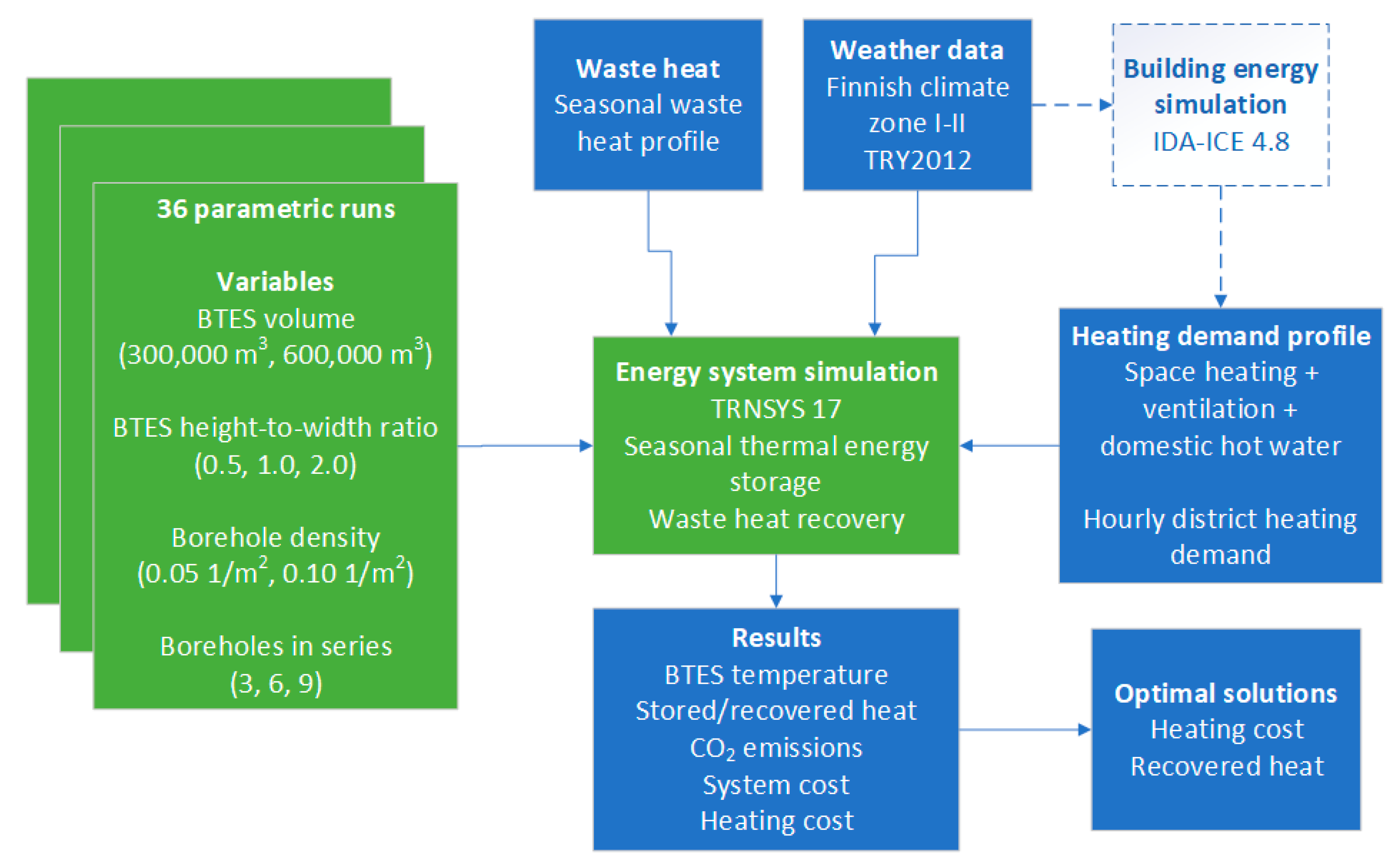
2.4. Parametric Runs
3. Results
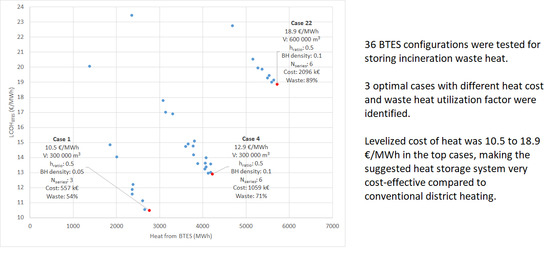
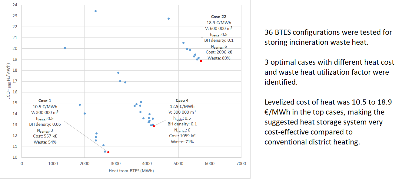
3.1. All Cases
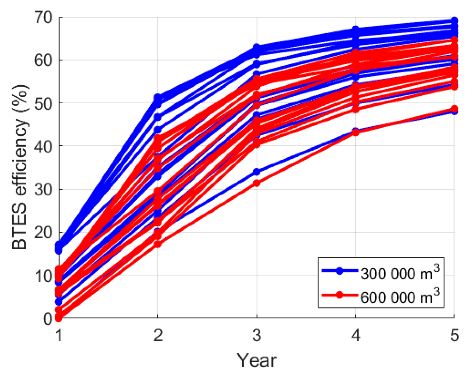
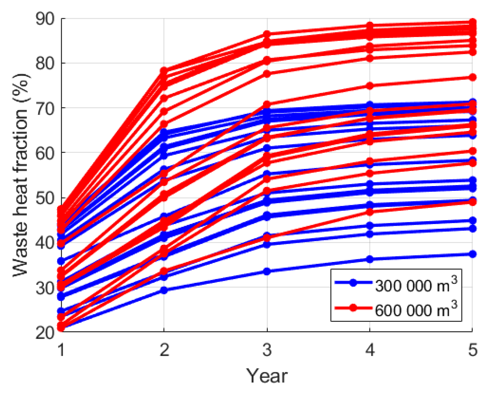
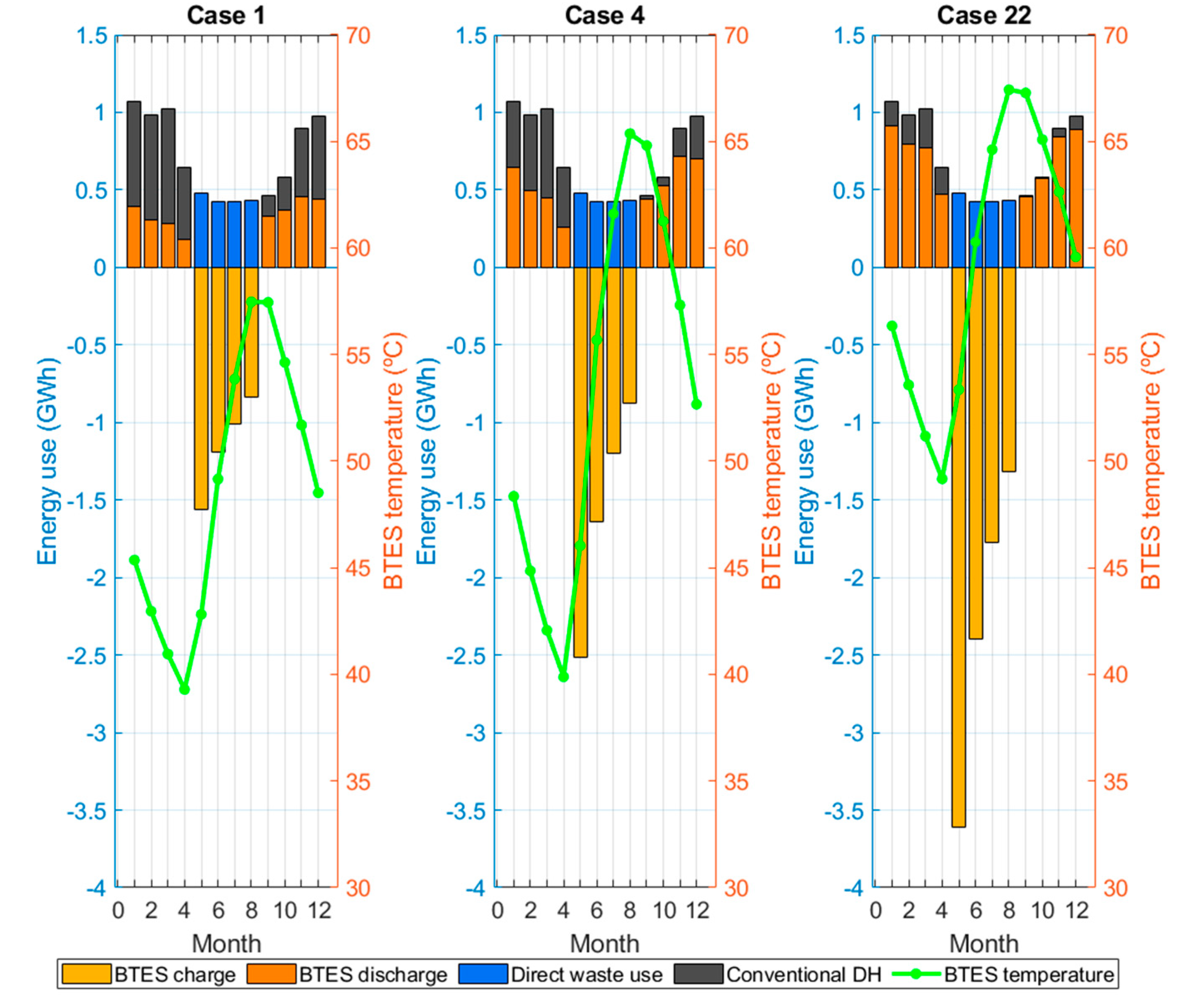
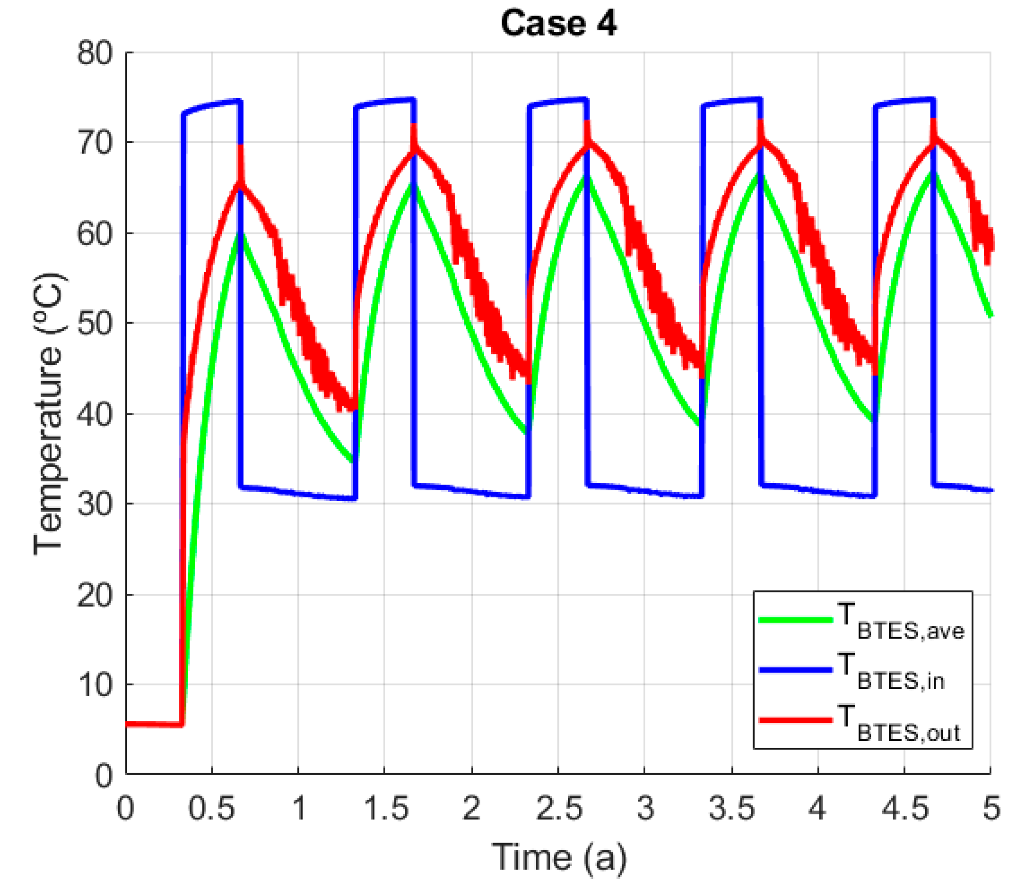
3.2. Development of BTES State
3.3. Performance of the Best Cases
4. Discussion
4.1. Toward a Net-Zero Energy District
4.2. Implications and Potential
4.3. Weaknesses and Reliability
5. Conclusions
Author Contributions
Funding
Acknowledgments
Conflicts of Interest
References
- Patronen, J.; Kaura, E.; Torvestad, C. Nordic Heating and Cooling-Nordic Approach to EU’s Heating and Cooling Strategy-Nordic Council of Ministers; TemaNord: Copenhagen, Denmark, 2017. [Google Scholar]
- Vertanen, V. Municipal Waste Treatment in Finland. Available online: http://www.stat.fi/til/jate/2016/13/jate_2016_13_2018-01-15_tau_001_en.html (accessed on 2 May 2019).
- Gao, L.; Zhao, J.; Tang, Z. A Review on Borehole Seasonal Solar Thermal Energy Storage. Energy Procedia 2015, 70, 209–218. [Google Scholar] [CrossRef] [Green Version]
- Hirvonen, J.; Rehman, H.; Sirén, K. Techno-economic optimization and analysis of a high latitude solar district heating system with seasonal storage, considering different community sizes. Sol. Energy 2018, 162, 472–488. [Google Scholar] [CrossRef] [Green Version]
- Hirvonen, J.; Sirén, K. A novel fully electrified solar heating system with a high renewable fraction-Optimal designs for a high latitude community. Renew. Energy 2018, 127, 298–309. [Google Scholar] [CrossRef]
- Nordell, B.; Andersson, O.; Scorp, A.L. The High Temperature Borehole Thermal Energy Storage Plant in Emmaboda-Report from the First Three Years of Operation 2010–2013, Half-Time Report Luleå University of Technology. Available online: https://www.researchgate.net/publication/273899339_The_high_temperature_Borehole_Thermal_Energy_Storage_plant_in_Emmaboda_-_Report_from_the_first_three_years_of_operation_2010-2013_half-time_report (accessed on 2 April 2019).
- Nordell, B.; Andersson, O.; Rydell, L.; Scorpo, A.L. Long-term performance of the HT-BTES in Emmaboda, Sweden. Presented at Greenstock 2015. In Proceedings of the International Conference on Underground Thermal Energy Storage, Beijing, China, 19 May 2015. [Google Scholar]
- Nilsson, E.; Rohdin, P. Performance evaluation of an industrial borehole thermal energy storage (BTES) project—Experiences from the first seven years of operation. Renew. Energy 2019, 143, 1022–1034. [Google Scholar] [CrossRef]
- Guo, F.; Zhu, X.; Zhang, J.; Yang, X. Large-scale living laboratory of seasonal borehole thermal energy storage system for urban district heating. Appl. Energy 2020, 264, 114763. [Google Scholar] [CrossRef]
- Rapantova, N.; Pospisil, P.; Koziorek, J.; Vojcinak, P.; Grycz, D.; Rozehnal, Z. Optimisation of experimental operation of borehole thermal energy storage. Appl. Energy 2016, 181, 464–476. [Google Scholar] [CrossRef]
- Finnish Meteorological Institute. Test Reference Years for Energy Calculations [In Finnish]. Available online: https://ilmatieteenlaitos.fi/energialaskennan-testivuodet-nyky (accessed on 16 November 2020).
- Ministry of the Environment. Ympäristöministeriön asetus uuden rakennuksen energiatehokkuudesta (1010/2017) (Decree of the Ministry of the Environment on the energy performance of the new building (1010/2017) [In Finnish]. Available online: https://www.finlex.fi/fi/laki/alkup/2017/20171010 (accessed on 16 November 2020).
- Hirvonen, J.; Jokisalo, J.; Heljo, J.; Kosonen, R. Towards the EU emissions targets of 2050: Optimal energy renovation measures of Finnish apartment buildings. Int. J. Sustain. Energy 2018. [Google Scholar] [CrossRef] [Green Version]
- EQUA Simulation AB, Solna, Sweden. IDA ICE—Simulation Software. Available online: https://www.equa.se/en/ida-ice (accessed on 16 November 2020).
- Flynn, C.; Sirén, K. Influence of location and design on the performance of a solar district heating system equipped with borehole seasonal storage. Renew. Energy 2015, 81, 377–388. [Google Scholar] [CrossRef]
- Engineering Toolbox. Thermal Conductivity of Selected Materials and Gases. Available online: https://www.engineeringtoolbox.com/thermal-conductivity-d_429.html (accessed on 23 September 2020).
- Statistics Finland. Tilastokeskus-Energia ja päästöt. Available online: https://pxhopea2.stat.fi/sahkoiset_julkaisut/energia2019/html/suom0011.htm (accessed on 25 September 2020).
- European Commission. Commission Delegated Regulation Supplementing Directive 2010/31/EU of the European Parliament and of the Council on the Energy Performance of Buildings (Recast) by Establishing Energy Performance Requirements for Buildings and Building Elements. Available online: https://ec.europa.eu/transparency/regdoc/rep/3/2011/EN/3-2011-10050-EN-F1-1.Pdf (accessed on 10 September 2020).
- Pieskä, M. Discussion about Waste Heat Storage Potential by a Vaasan Sähkö Oy Representative; Westenergy Oy Ab: Kvevlax, Finland, 2018. [Google Scholar]
- Oy, Helen. Kaukolämmön energia- ja vesivirtamaksut 1.10.2020 alkaen [District Heating Energy and Capacity Costs]. Available online: https://www.helen.fi/globalassets/hinnastot-ja-sopimusehdot/lampo-ja-jaahdytys/kotitaloudet/kaukolammon-energia-ja-vesivirtamaksut-01102020.pdf (accessed on 10 September 2020).
- Statistics Finland. Waste Treatment in 2018. Available online: https://www.stat.fi/til/jate/2018/jate_2018_2020-06-17_tau_002_en.html (accessed on 28 September 2020).
- Eurostat. Municipal Waste Statistics-Statistics Explained. Available online: https://ec.europa.eu/eurostat/statistics-explained/index.php/Municipal_waste_statistics (accessed on 28 September 2020).
- Heat Roadmap Europe. Heating and Cooling Energy Demands. Available online: https://heatroadmap.eu/heating-and-cooling-energy-demand-profiles/ (accessed on 28 September 2020).
- Statistics Finland. Consumer Prices of Heating Energy in March 2020. Available online: https://www.stat.fi/til/ehi/2020/01/ehi_2020_01_2020-06-11_tau_003_en.html (accessed on 25 September 2020).
- Poredos, A.; Kitanovski, A. Exergy loss as a basis for the price of thermal energy. Energy Convers. Manag. 2001, 43, 2163–2173. [Google Scholar] [CrossRef]
- Arabkoohsar, A.; Alsagri, A.S. Thermodynamic analysis of ultralow-temperature district heating system with shared power heat pumps and triple-pipes. Energy 2020, 194, 116918. [Google Scholar] [CrossRef]


| Case | VBTES (m3) | hratio (m/m) | BH Density (1/m2) | Nseries |
|---|---|---|---|---|
| 1 | 300,000 | 0.5 | 0.05 | 3 |
| 2 | 300,000 | 0.5 | 0.1 | 3 |
| 3 | 300,000 | 0.5 | 0.05 | 6 |
| 4 | 300,000 | 0.5 | 0.1 | 6 |
| 5 | 300,000 | 0.5 | 0.05 | 9 |
| 6 | 300,000 | 0.5 | 0.1 | 9 |
| 7 | 300,000 | 1 | 0.05 | 3 |
| 8 | 300,000 | 1 | 0.1 | 3 |
| 9 | 300,000 | 1 | 0.05 | 6 |
| 10 | 300,000 | 1 | 0.1 | 6 |
| 11 | 300,000 | 1 | 0.05 | 9 |
| 12 | 300,000 | 1 | 0.1 | 9 |
| 13 | 300,000 | 2 | 0.05 | 3 |
| 14 | 300,000 | 2 | 0.1 | 3 |
| 15 | 300,000 | 2 | 0.05 | 6 |
| 16 | 300,000 | 2 | 0.1 | 6 |
| 17 | 300,000 | 2 | 0.05 | 9 |
| 18 | 300,000 | 2 | 0.1 | 9 |
| 19 | 600,000 | 0.5 | 0.05 | 3 |
| 20 | 600,000 | 0.5 | 0.1 | 3 |
| 21 | 600,000 | 0.5 | 0.05 | 6 |
| 22 | 600,000 | 0.5 | 0.1 | 6 |
| 23 | 600,000 | 0.5 | 0.05 | 9 |
| 24 | 600,000 | 0.5 | 0.1 | 9 |
| 25 | 600,000 | 1 | 0.05 | 3 |
| 26 | 600,000 | 1 | 0.1 | 3 |
| 27 | 600,000 | 1 | 0.05 | 6 |
| 28 | 600,000 | 1 | 0.1 | 6 |
| 29 | 600,000 | 1 | 0.05 | 9 |
| 30 | 600,000 | 1 | 0.1 | 9 |
| 31 | 600,000 | 2 | 0.05 | 3 |
| 32 | 600,000 | 2 | 0.1 | 3 |
| 33 | 600,000 | 2 | 0.05 | 6 |
| 34 | 600,000 | 2 | 0.1 | 6 |
| 35 | 600,000 | 2 | 0.05 | 9 |
| 36 | 600,000 | 2 | 0.1 | 9 |
| Case | VBTES | hratio | BH Density | Nseries | BTES Heat Output | BTES Efficiency | Waste Fraction | LCOH |
|---|---|---|---|---|---|---|---|---|
| (m3) | (m/m) | (1/m2) | - | (MWh) | % | % | (€/MWh) | |
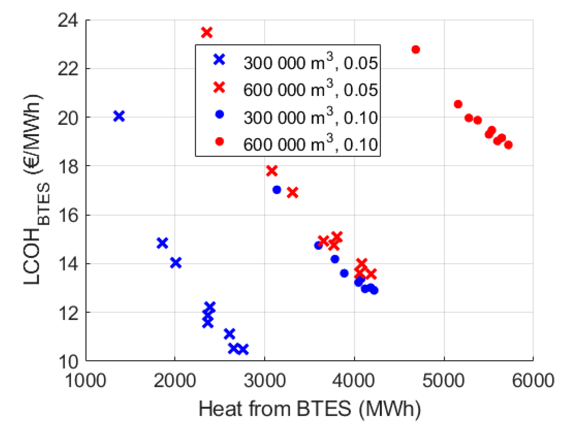
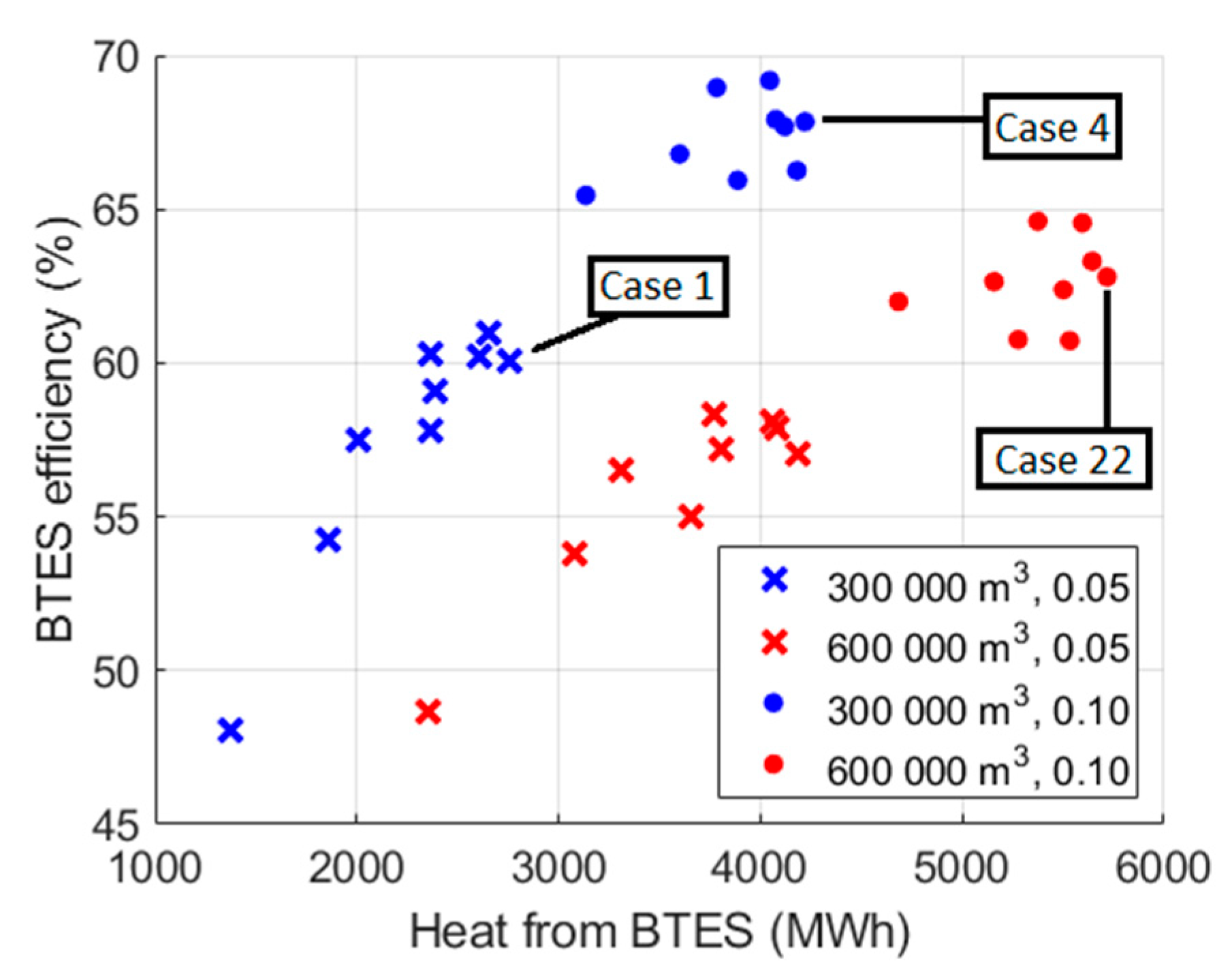
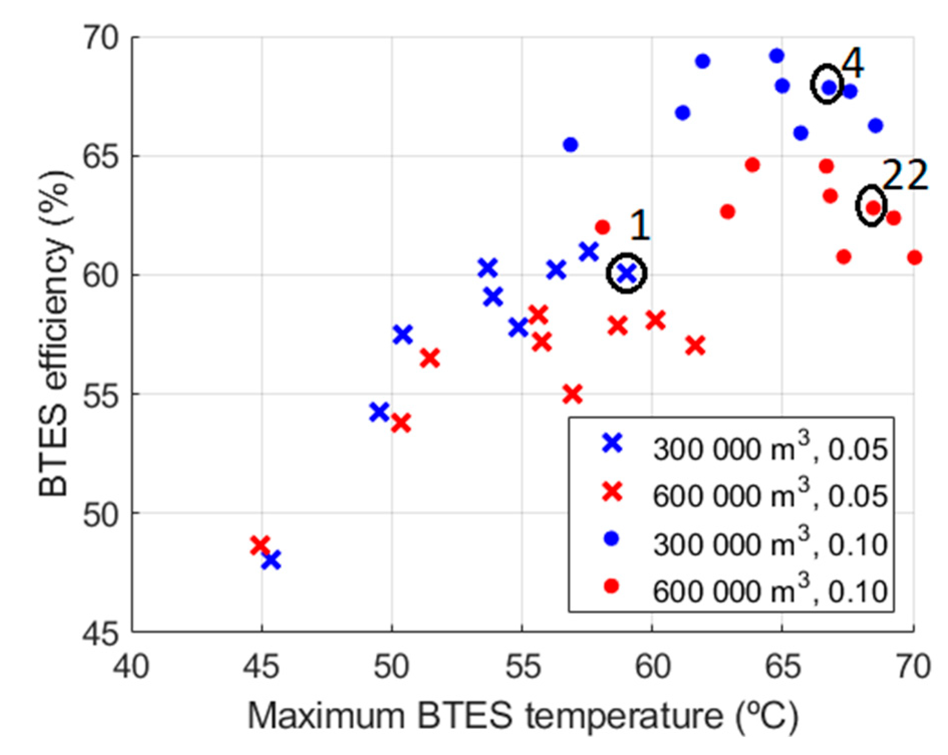
| 1 | 300,000 | 0.5 | 0.05 | 3 | 2761 | 60.1 | 53.9 | 10.5 |
| 7 | 300,000 | 1 | 0.05 | 3 | 2652 | 61.0 | 52.6 | 10.5 |
| 3 | 300,000 | 0.5 | 0.05 | 6 | 2607 | 60.2 | 52.0 | 11.1 |
| 13 | 300,000 | 2 | 0.05 | 3 | 2368 | 57.8 | 49.2 | 11.6 |
| 9 | 300,000 | 1 | 0.05 | 6 | 2366 | 60.3 | 49.2 | 11.9 |
| 5 | 300,000 | 0.5 | 0.05 | 9 | 2385 | 59.1 | 49.4 | 12.2 |
| 4 | 300,000 | 0.5 | 0.1 | 6 | 4220 | 67.8 | 71.3 | 12.9 |
| 8 | 300,000 | 1 | 0.1 | 3 | 4119 | 67.7 | 70.1 | 13.0 |
| 2 | 300,000 | 0.5 | 0.1 | 3 | 4181 | 66.3 | 70.8 | 13.0 |
| 10 | 300,000 | 1 | 0.1 | 6 | 4046 | 69.2 | 69.2 | 13.2 |
| 6 | 300,000 | 0.5 | 0.1 | 9 | 4076 | 67.9 | 69.5 | 13.4 |
| 19 | 600,000 | 0.5 | 0.05 | 3 | 4186 | 57.1 | 70.9 | 13.6 |
| 14 | 300,000 | 2 | 0.1 | 3 | 3887 | 65.9 | 67.3 | 13.6 |
| 25 | 600,000 | 1 | 0.05 | 3 | 4060 | 58.1 | 69.4 | 13.6 |
| 21 | 600,000 | 0.5 | 0.05 | 6 | 4078 | 57.9 | 69.6 | 14.0 |
| 11 | 300,000 | 1 | 0.05 | 9 | 2007 | 57.5 | 44.9 | 14.1 |
| 12 | 300,000 | 1 | 0.1 | 9 | 3783 | 69.0 | 66.0 | 14.2 |
| 16 | 300,000 | 2 | 0.1 | 6 | 3600 | 66.8 | 63.9 | 14.7 |
| 27 | 600,000 | 1 | 0.05 | 6 | 3774 | 58.3 | 65.9 | 14.8 |
| 15 | 300,000 | 2 | 0.05 | 6 | 1857 | 54.2 | 43.1 | 14.8 |
| 31 | 600,000 | 2 | 0.05 | 3 | 3660 | 55.0 | 64.6 | 14.9 |
| 23 | 600,000 | 0.5 | 0.05 | 9 | 3804 | 57.2 | 66.3 | 15.1 |
| 29 | 600,000 | 1 | 0.05 | 9 | 3306 | 56.5 | 60.4 | 16.9 |
| 18 | 300,000 | 2 | 0.1 | 9 | 3135 | 65.5 | 58.3 | 17.0 |
| 33 | 600,000 | 2 | 0.05 | 6 | 3082 | 53.8 | 57.7 | 17.8 |
| 22 | 600,000 | 0.5 | 0.1 | 6 | 5717 | 62.8 | 89.1 | 18.9 |
| 28 | 600,000 | 1 | 0.1 | 6 | 5595 | 64.6 | 87.7 | 19.0 |
| 24 | 600,000 | 0.5 | 0.1 | 9 | 5644 | 63.3 | 88.2 | 19.2 |
| 26 | 600,000 | 1 | 0.1 | 3 | 5501 | 62.4 | 86.5 | 19.3 |
| 20 | 600,000 | 0.5 | 0.1 | 3 | 5533 | 60.7 | 86.9 | 19.5 |
| 30 | 600,000 | 1 | 0.1 | 9 | 5375 | 64.6 | 85.0 | 19.9 |
| 32 | 600,000 | 2 | 0.1 | 3 | 5277 | 60.8 | 83.9 | 20.0 |
| 17 | 300,000 | 2 | 0.05 | 9 | 1380 | 48.1 | 37.4 | 20.1 |
| 34 | 600,000 | 2 | 0.1 | 6 | 5157 | 62.6 | 82.4 | 20.5 |
| 36 | 600,000 | 2 | 0.1 | 9 | 4684 | 62.0 | 76.8 | 22.8 |
| 35 | 600,000 | 2 | 0.05 | 9 | 2352 | 48.7 | 49.0 | 23.5 |
Publisher’s Note: MDPI stays neutral with regard to jurisdictional claims in published maps and institutional affiliations. |
© 2020 by the authors. Licensee MDPI, Basel, Switzerland. This article is an open access article distributed under the terms and conditions of the Creative Commons Attribution (CC BY) license (http://creativecommons.org/licenses/by/4.0/).
Share and Cite
Hirvonen, J.; Kosonen, R. Waste Incineration Heat and Seasonal Thermal Energy Storage for Promoting Economically Optimal Net-Zero Energy Districts in Finland. Buildings 2020, 10, 205. https://0-doi-org.brum.beds.ac.uk/10.3390/buildings10110205
Hirvonen J, Kosonen R. Waste Incineration Heat and Seasonal Thermal Energy Storage for Promoting Economically Optimal Net-Zero Energy Districts in Finland. Buildings. 2020; 10(11):205. https://0-doi-org.brum.beds.ac.uk/10.3390/buildings10110205
Chicago/Turabian StyleHirvonen, Janne, and Risto Kosonen. 2020. "Waste Incineration Heat and Seasonal Thermal Energy Storage for Promoting Economically Optimal Net-Zero Energy Districts in Finland" Buildings 10, no. 11: 205. https://0-doi-org.brum.beds.ac.uk/10.3390/buildings10110205