
Load-Carrying Capacity of Compressed Wall-Like RC Columns Strengthened with FRP


Department of Engineering, University of Campania “Luigi Vanvitelli”, 81031 Aversa, Italy
*
Author to whom correspondence should be addressed.
Buildings 2021, 11(7), 285; https://0-doi-org.brum.beds.ac.uk/10.3390/buildings11070285
Submission received: 27 April 2021
/
Revised: 15 June 2021
/
Accepted: 26 June 2021
/
Published: 30 June 2021
(This article belongs to the Section Building Structures)
Abstract
:The analytical prediction of the effectiveness of fiber-reinforced polymer (FRP) in the confinement of a rectangular reinforced concrete (RC) column with a high aspect ratio (wall-like) still has an uncertain solution. In this paper, a numerical investigation of the axial response of RC wall-like columns strengthened with FRP systems was developed. Analytical solutions proposed in the literature for the assessment of the axial load capacity were presented and compared with each other and with the available experimental results. Moreover, non-linear finite element analysis was carried out, and the results were discussed, providing a simple model for the assessment of the axial compressive strength of wall-like RC columns strengthened with FRP.
1. Introduction
Fiber-reinforced polymer (FRP) systems have been widely used to improve the performance of reinforced concrete compression members in terms of strength and ductility. Such a solution is one of the most common techniques to upgrade both building columns and bridge piers, as it ensures an easy and fast installation with high durability and a low impact on the use of the structure, without increasing the mass and geometrical dimensions of the cross-section. FRP confinement is generally accomplished by placing the fibers transverse to the longitudinal axis of the member, providing a passive confinement. This effect is induced by the lateral pressure exerted on the core of the cross-section as a result of the concrete’s radial expansion due to the Poisson effect and internal cracking.
The confining action of FRP jacketing or wrapping is optimal for circular columns, whose geometric configuration allows the fiber to be the most effective, inducing a uniform and “triaxial” stress state on the entire cross-section. Moreover, the failure of the strengthened member is generally due to obtaining the ultimate strain of the FRP sheet. Extensive experimental and numerical investigations have been carried out to establish the effectiveness of FRP confinement on circular columns [1,2,3,4,5].
The FRP confining system is less effective in the case of prismatic cross-sections (i.e., square or rectangular), where the presence of straight sides and corners reduces the confining action of the FRP wrapping, and the lateral confining pressure varies from the maximum at the corners and the diagonals to the minimum between the edges. Consequently, the cross-section is only partially confined and experiences a lesser increase in strength and ductility than columns with circular sections [6,7,8,9,10]. The failure of this member can occur when the strain of the FRP sheets is lower than the ultimate strain [11,12,13,14]. Extensive research works have also been reported in the literature on axially loaded RC rectangular columns with an aspect ratio that ranges between one and two, strengthened with FRP composites. Consequently, the guidelines ACI 440.2R [15] and CNR-DT 200 R1 [16] provide instructions and formulae to predict the ultimate stress and strain of FRP-confined concrete limited to elements with this side aspect ratio.
A critical review of the state-of-the-art design methodologies for FRP-confined reinforced concrete columns with prismatic sections was presented by Rocca et al. [17]. The authors highlighted the need for further studies to investigate the effects of the size of the cross-section and its aspect ratio, the longitudinal steel reinforcement instability, the concrete dilation, and the contribution of the internal transverse steel reinforcement. The effect of an aspect ratio up to 2.25 was investigated by Li et al. [18]. Based on the experimental results, the authors compared existing confining models for rectangular RC columns, concluding that the strength enhancement levels decreased with an increase in the aspect ratio.
On the other hand, in the case of wall-like columns (i.e., a column member with a rectangular cross-section with the ratio between the sides higher than approximately three), the effectiveness of the FRP wrapping was further reduced [19,20,21]. In this case, the confinement effect, not inducing a significant change of the failure mode, is, however, able to delay the buckling of bars, restraining the spalling of the cover and allowing the compressive concrete strains to attain higher values, thus resulting in a higher load-carrying capacity of the member and significant ductility enhancement [21,22,23]. Although many applications of wall-like columns strengthened using FRP composites have been developed in the practice, a limited number of test data, analytical solutions, and finite element models are available in the literature. Thus, wall-like columns are of particular interest because of the lack of specific provisions to predict their ultimate strength and ductility capacity when strengthened with FRP systems.
This paper compared the existing analytical solutions proposed in the literature to predict the axial load capacity of RC wall-like columns strengthened using FRP composites, with the available experimental results. The main focus was on analytical models consisting of closed-form expressions, referred to as design-oriented models. Furthermore, finite element models (FEM) using the ANSYS software for FRP-strengthened, wall-like RC columns were also developed and used to assess their ultimate axial load capacity. The accuracy of the analytical solutions and the finite element models at estimating the available test results was also evaluated. Finally, a modified analytical model was calibrated starting from the available experimental results. On the other hand, the finite element analysis (FEA) results were used to calibrate a simple model for the assessment of the axial load capacity of RC wall-like columns strengthened with FRP wrapping.
2. Literature Review
The first experimental studies on the strengthening of wall-like RC columns with FRP systems were carried out by Neale et al. [24] and Chiew et al. [25]. Both works proposed and tested the use of glass and carbon-fiber composites using various strengthening schemes. They agreed that the use of glass-fiber-reinforced polymers (GFRP) was preferable to carbon-fiber-reinforced polymers (CFRP), as the former have a thicker section, which offers higher stability against buckling. Although a satisfactory increase in axial load capacity was achieved in that study, the test program did not simulate the actual loading conditions of typical columns.
Then, Tan [20] investigated the strength-enhancement characteristics of axially loaded columns bonded by external FRP systems with the fibers oriented both in the longitudinal and transverse directions. Experimental tests were carried out on wall-like RC columns with a cross-sectional aspect ratio of 3.65. It was found that the confinement effect of transverse fiber sheets led to an increase in the uniaxial compressive strength of the confined concrete, resulting in an increasing contribution to the load-carrying capacity of the column. The measured ultimate strength of the columns was compared with the analytical model, adopting an extension of the Mander model [6,26], and the results showed good agreement between the measured and predicted column ultimate strengths.
Again, Tanwongsval et al. [19] and Maalej et al. [27] investigated the FRP strengthening effects on the ultimate axial load capacity of RC columns with the same aspect ratio, using two different strengthening schemes. First, GFRP sheets were wrapped directly around the column. Then, the GFRP was applied after modifying the rectangular cross-section to a more rounded one. The results highlighted an increase of more than 30% in the ultimate strength of the strengthened member with modified cross-sections. They also proposed an analytical model that was an extension of the previous studies carried out by Saatcioglu and Razvi [28], and Yalcin and Saatcioglu [29]. A parametric study was also carried out, and the effect of the aspect ratio and the number of horizontal and longitudinal FRP layers on the ultimate strength of the axially-loaded columns were highlighted. An acceptable agreement between the measured and predicted column ultimate loads and displacements, using that model, was observed.
Subsequently, Prota et al. [21] investigated the effectiveness of GFRP laminates on the increase in axial strength of concentrically loaded RC wall-like columns. They highlighted that GFRP confinement could increase strength and ductility of the member, and that the failure of the confined wall-like columns is controlled by the shape of the cross-section and occurs at transverse strains in the jacket much lower than the ultimate strains of the fibers. Then, starting from the available experimental programs developed on wall-like column confined with FRP wrapping, Lignola et al. [30] provides a “biaxial” stress state model for the analytical prediction of the axial load capacity of these cross-sections. A good agreement between experimental and numerical outcomes was found only if proper values of FRP strain at ultimate condition are provided.
Recently, Triantafillou et al. [31] investigated FRP confinement of wall-like RC columns in a systematic way, by examining a number of parameters not yet addressed. In particular, the effectiveness of different type of anchors, the role of different cross-section ratios (3 and 4), the number of layers, the local strengthening at the corners and the reduction of aspect ratio by cross-section enlargement, are taken into account in this experimental study. An analytical model is also proposed for the assessment of the ultimate load capacity of axially loaded columns, which is found in good agreement with test results.
More recently, Vuggumudi et al. [32,33] proposed semi-empirical solutions to predict the axial and lateral capacities of wall-like RC columns strengthened using FRP composites. The proposed solutions are consistent with the procedure suggested by ACI 440.2R-08 [34] for the definition of axial force and bending moment interaction diagram for rectangular columns with aspect ratio lower than 2.0. The proposed semi-empirical solutions, validated with the test results is proposed to be used for the design of wall-like RC columns with aspect ratio greater than 2.0 strengthened with FRP composites and without any shape modification.
3. Materials and Methods
3.1. Analytical Models
The strength enhancement in columns using FRP systems mainly derives from two sources: (i) the confinement effect of transverse fiber sheets, (ii) the directly contribution of longitudinal fiber sheets. The former leads to an increase in the uniaxial compressive strength of the confined concrete, resulting subsequently in an increase in the contribution of concrete to the load-carrying capacity of the column. The latter is due to the load-carrying capacity of the longitudinal fiber sheets. It should be noted that, in the former contribution the effects of the FRP system on restraining the cover spalling and delaying the bars buckling are also included. Moreover, the latter contribution can be taken into account only if the longitudinal fiber sheet are adequately restrained from outward buckling by transverse fiber sheets.
In general, the axial load capacity of wall-like column strengthened with FRP composites , without any safety factors can be calculated by adding the compression load carried by the confined concrete, , the compression load carried by steel reinforcement, , and the compression load directly carried by the longitudinal fiber sheets, [20]:
In Equation (1), and are the gross cross-sectional area of the column and the confined concrete strength; and are the total area and the yield strength of longitudinal steel reinforcement; is the cross-sectional area of longitudinal fiber sheets (of thickness ); is the stress in the longitudinal fiber sheets, given as , where is the Young’s modulus of fiber sheets and is their longitudinal strain at peak.
For a rectangular reinforced concrete column, measuring in cross-sectional dimensions, where , according to the formulation proposed by Lam and Teng [10] the ratio between the average confined concrete strength, , and the unconfined concrete strength can be expressed as:
In Equation (2), is the confinement effectiveness coefficient assumed equal to 3.3 by Lam and Teng [35]; is the shape factor accounting for the effect of non-uniform confinement; is the ratio between the equivalent confining pressure and the strength of unconfined concrete. The equivalent confining pressure is expressed as:
where is the ultimate strain of FRP and is the total thickness of FRP sheets placed in horizontal direction. In Equation (3), D is defined as the diameter of the equivalent circular section, assumed as the diagonal distance in the case of rectangular section. The shape factor generally depend on two parameters, the effectively confined area ratio and the reciprocal of the aspect ratio . Within the model proposed by Lam and Teng [10], it is assumed that only the concrete area contained by four parabolas having initial slopes tangent to the diagonal lines is effectively confined (see Figure 1a). The effective confinement area ratio generally depends on the ratio of longitudinal steel reinforcement , on the corner radius , and on and that are the distances between the corner points on the two sides. The analytical expression of the confined area ratio is reported in Table 1.
Subsequently, Tan [20] for the assessment of the average confined concrete strength, , in the case of wall-like section adopted the following expression derived by Wang and Restrepo [26]:
In Equation (4), predicts the confined compressive strength in “triaxial” stress state (as in Mander et al. [7]), and is the parameter that takes into account all the variations from the “biaxial” stress state. These concrete strength enhancement factors are expressed as follows:
where is the effective lateral confining pressures acting in the direction parallel to the larger side of the cross-section, given by:
Notice that in Equation (4), is a reduction parameter. Moreover, Tan [20] assumed that the axial load capacity is ranged between a lower-bound value and an upper-bound value, associated to different models used to define the effective confined concrete area, and to the corresponding shape factor . In the former model, associated to the lower bound, it is assumed that only the corners of the columns act as anchor points, and that the four parabolas intersect the edges with an initial tangent slope of 45° (see Figure 1b). In the latter model, associated to the upper bound, it is assumed that internal links provide additional anchor points and help in restraining the concrete from bulging out, resulting in a larger confining effect (see Figure 1c). Accordingly, the effectively confined area ratio is defined in Table 1. Within this expression, is assumed in the lower bound model. On the other hand, represents the distance between adjacent anchors points on the large side, being n the number of the internal anchor points, in the upper bound model. In the definition of the compressive axial load carried by the confined concrete, , the value of is reduced by a factor of 0.85.
Then, Maalej et al. [27] proposed an expression for the assessment of the average confined concrete strength, , similar to the Equation (2), wherein the equation suggested by Saatcioglu and Razvi [28] for the confinement effectiveness coefficient is adopted. Authors also proposed to add the contribution of the FRP wraps to the effective lateral confining pressure from the transverse steel reinforcements, to obtain the total effective lateral pressure exerted on the concrete core. In addition, the concrete cover is also confined by the FRP wraps and this must be accounted for in the evaluation of the axial load capacity of the column. To determine the equivalent confining pressure, the rectangular section is transformed into an equivalent circular section and can be expressed as in Equation (3), if the effects of the longitudinal fiber sheets are neglected. Moreover, to define the effectively confined concrete area, the procedure proposed by Sheikh and Uzumeri [36] is used, wherein it is assumed that the ineffectively confined areas are enclosed by parabolas with an initial tangent slope of 45° as in the Figure 1b. The results of this procedure is summarized in the expression of the ratio reported in Table 1. Notice that the unconfined areas may overlap along the longer direction as the aspect ratio increases. When this situation occurs the ratio is lower than 1 and the overlapping area is directly deduced (see Table 1). On the other hand, when the overlap does not occur the ratio has to be assumed equal to 1. Additionally, in this case, in the definition of , the value of is reduced by a factor of 0.85.
Again, Lignola et al. [22] observes that the confining stresses path rapidly changes in a straight field moving away from the corners. According to this, a “biaxial” compression model can be considered for the cross-section assuming that is the maximum principal stress, is the intermediate principal stress, and the minimum principal stress is equal to zero [30]. According to these last assumptions the following expression for the ratio between the average confined concrete strength, , and the unconfined concrete strength is given:
where the effective lateral confining pressures, , is calculated using the Equations (3) and (7), assuming that . The average confined concrete strength is then applied to the entire gross cross-sectional area, , in order to evaluate the axial load capacity of the column.
Recently, Triantafillou et al. [31] proposed some changes to the model of Lam and Teng [10] to explicitly account for the presence of anchors of different type or internal links. In particular, the equivalent confining pressure of Equation (3) is reduced by two coefficients and . The former accounts for the effect of the chamfer radius at corner. The latter accounts for all the other effects (i.e., duration of loading, buckling of the longitudinal steel reinforcement, etc.). In particular, the corner radius reduction factor is given by:
The equivalent confining pressure is calculated using the Equation (3), wherein the equivalent circular cross-section is defined as the one with a diameter D that has the same FRP volumetric ratio of the original rectangular section (see Table 1). The effectively confined area ratio is defined using an approach similar to that proposed by Tan [20]. However, in the expression of the ratio, n is the number of anchors and is the vertical spacing between the anchors. In particular, for columns with heavy anchors.
Finally, Vuggumudi et al. [32] provides an expression to be used for the assessment of the ratio in the case of wall-like columns. The expression is very similar to that proposed by Lam and Teng [10], and then transposed in ACI440.2R [34] and CNR [16] for columns having aspect ratio less than 2.0. Based on test results a specific value of 1.78 instead of 3.3, is proposed for in the case of RC column with aspect ratio greater than 2. An equivalent circular cross-section and an expression for the ratio similar to that proposed by Lam and Teng [10] (see Equation (4)) is used in the assessment of the shape factor .
The effects of the aspect ratio, , on the effective confinement area ratio, for each simple model discussed here, are presented in Figure 2 assuming the corner radius ratio , and longitudinal steel reinforcement ratio . Notice that according to Tan [20] and Triantafillou et al. [31] models, the effective confinement area ratio is also plotted as function of the number of internal links.
3.2. Experimental Results
For the purpose of this study, a number of rectangular concrete wall-like columns strengthened with FRP systems, chosen between the test data available in literature, are considered. In particular, these experimental results have been derived by studies of Tan [20], Tanwongsval et al. [19], Prota et al. [21], Triantafillou et al. [31], and Vuggumudi et al. [32]. These test data cover wall-like columns having aspect ratios closed in the range between 3 and 4, strengthened with one or more layers of CFRP or GFRP placed in transverse or longitudinal direction.
Tan [20] tested 52 wall-like RC columns with having cross-section and in height, thereby representing half scale of prototype columns. All the specimens had a longitudinal steel reinforcement ratio of 2.2% and with transverse reinforcement consisting of diameter stirrups and links at a spacing of . Both glass and carbon laminates with unidirectional fiber texture were used to externally bond the axial loaded member. Different number of plies of longitudinal and transverse sheets were accounted for.
Tanwongsval et al. [19] tested five wall-like RC columns having the same cross-section and transverse reinforcement with a longitudinal steel ratio equal to 2.8%. Columns were externally bonded with GFRP laminates in longitudinal and transverse directions; the opportunity of installing the FRP after enlarging the cross-section with two semi-cylindrical portions made of high strength mortar was also explored.
Prota et al. [21] carried out experimental results on nine RC wall-like columns having cross-section and height identical to those considered in Tanwongsval et al. [19], Tan [20]. Transverse links were used to ensure the effectiveness of the steel stirrup, and a corner radius, , of 20 mm was made for the cross-sections. Three columns were tested as control. Six other columns were strengthened with GFRP laminates in both the parallel direction and perpendicular direction to the member axis; only in one case the possibility to bond the member with two plies of quadridirectional GFRP laminates was also taken into account.
Triantafillou et al. [31] tested 45 wall-like RC columns constructed in 15 different designs, each with three identical specimen. Two groups of columns designs having a height of for all, and a cross-sections of and of , respectively, were tested. The corners of the cross-section were chamfered to a radius, , of . A longitudinal steel reinforcement ratio of 1%, and transverse reinforcement consisting of diameter stirrups at a spacing of , were used. The columns were generally strengthened with two layers of CFRP, and eventually with different configurations of fiber spike anchors or thick layer of mortar.
Vuggumudi et al. [32], tested six prototypes of RC rectangular column with a height of , a cross-section of , and without any modification of cross-section. The three control columns and the corresponding three columns strengthened with two layers of unidirectional carbon fiber cloth are tested under axial loads, lateral loads, and combined axial and lateral loads.
More details on the geometrical and mechanical properties of the tested wall-like columns are reported in Table 2. In particular, wall-like columns strengthened with unidirectional longitudinal or transverse FRP sheets, without any modification of the cross-section shape or cover (i.e., add of high strength repair mortar, plaster finishes, etc.) and tested under axial loads are taken into account.
3.3. Numerical Modeling
Starting from the analysis of the experimental results of the control and wrapped wall-like columns, with an aspect ratio ranging between 2.6 and 4, it is observed that the increase of their ultimate strength is mainly related to the ability of the FRP wrapping to restrain the cover spalling and delay bars buckling. Moreover, the estimation of the effect of the lateral confining pressure on the increase of the axial load capacity of wall-like columns strengthened with FRP wrapping yet represents an open issue. In order to investigate these aspects, finite element models of a number of tested wall-like columns above mentioned were developed using the commercial finite element software ANSYS. The main purpose is to quantify the accuracy of FEM models in the prediction of the axial load capacity of wall-like columns strengthened with FRP systems. To this aim, eight columns strengthened with only horizontal fiber sheets are selected.
To model the reinforced concrete columns in ANSYS, a three dimensional (3D) SOLID65 element with eight nodes is adopted. The element allows the treatment of nonlinear material properties and it is capable to take into account cracking under tension (in three orthogonal directions), crushing in compression, plastic deformation, and creep of concrete material. In particular, cubic elements with size up to 30 mm are used for the concrete core; prismatic elements with an aspect ratio up to 2 are used for the concrete cover.
To model the reinforcing bars, the LINK180 element with two nodes is used. This is a uniaxial tension-compression element, also capable of plastic deformation. To model the FRP strengthening, outlined as perimeter equivalent stirrups, LINK180 tension only elements are used. These elements have been horizontally placed on the external sides of the column and connected to each node of the mesh of the concrete cover. The nodes of both element (SOLID65 and LINK180) have three degrees of freedom: translations in the nodal x, y, and z directions. In Figure 3b, the outline of the 3D numerical model of the strengthened II4 column is shown.
The von Mises failure criterion is used to define concrete failure along with William and Warnke [37] constitutive model. The Kent and Park [38] stress–strain relationship is adopted to define the multi-linear isotropic concrete stress-strain curves. Within the FEM model, the first point of the stress-strain curve is defined as and it represents the linear branch that satisfies Hook’s law. The last two points define the linear branch of the stress–strain relationship. The modulus of elasticity of concrete is chosen as the secant modulus in which is the strain associated to a stress value of in the stress–strain model, and Poisson’s ratio is assumed to be . For implementation of the William and Warnke [37] material model in ANSYS [39], value of and are assumed for open and closed shear-transfer coefficient, respectively. Moreover, the uni-axial crushing stress is assumed equal to while the uniaxial cracking stress is assumed as . At last, the value of is chosen for the tensile crack factor. An isotropic elastic-perfectly plastic stress–strain relationship is considered for steel reinforcement with identical behavior in tension and compression. Bilinear von Mises plasticity failure criteria were assumed for steel. The modulus of elasticity of steel is considered as 210,000, and Poisson’s ratio is assumed to be . A uniaxial linear-elastic behavior is considered for the FRP strengthening materials with a tension only behavior. The material properties, as well as geometry, of the columns analyzed with ANSYS are the same used in the above analytical calculations already summarized in Table 2.
The boundary conditions at the bottom end of the columns were assumed to be fixed whereas only the axial degree of freedom was released at the top end. The validity of this assumption was confirmed through preliminary FE analyses developed on column models with unrestrained lateral boundary conditions. In order to assess the axial load capacity, non-linear static analysis was performed using the Newton–Raphson method. In particular, the quasi-static loading procedure was adopted by imposing vertical displacement variation through the top end of the column. In Figure 3a, the flow-chart of the numerical methodology is shown.
4. Results and Discussion
4.1. Analytical Results vs. Experimental Data
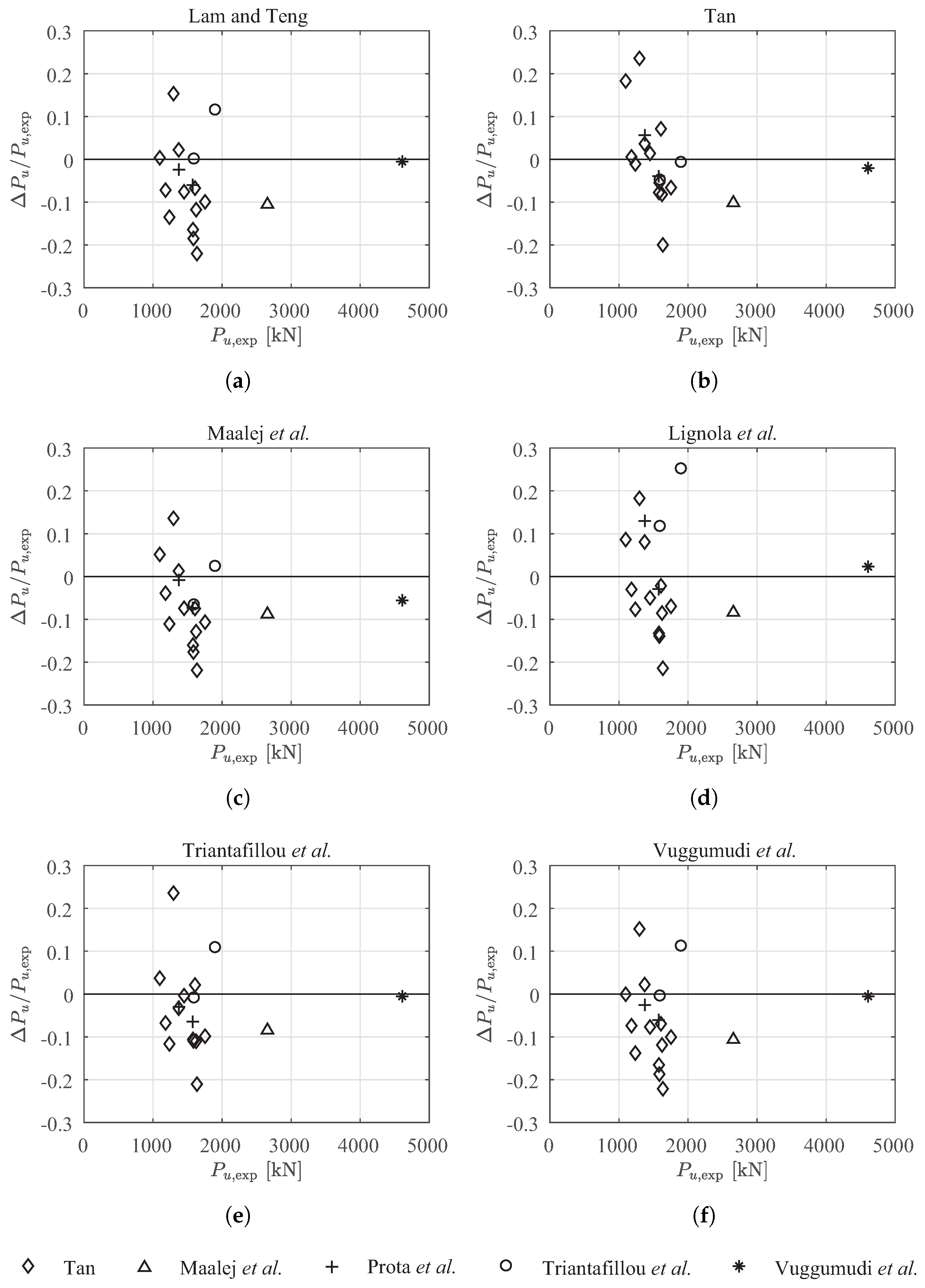
The effectiveness of the six design-oriented analytical models in the prediction of the axial load capacity for rectangular concrete wall-like columns strengthened with FRP systems is estimated and discussed here. The comparison between the predicted and measured values of the ultimate axial load capacity, for each analytical model above introduced is presented in the scatter plots of Figure 4 and in the error plots of Figure 5. According to Prota et al. [21], in the assessment of these results the conventional values of the longitudinal strain and transverse strain in FRP sheets are assumed equal to 0.4% and 0.1%, respectively. Moreover, the effect of the stirrups and internal links are taken into account in the selection of the alternative lower or upper bound condition within the analytical models proposed by Tan [20] and by Triantafillou et al. [31]. Furthermore, the directly contribution of longitudinal fiber sheets is taken into account.
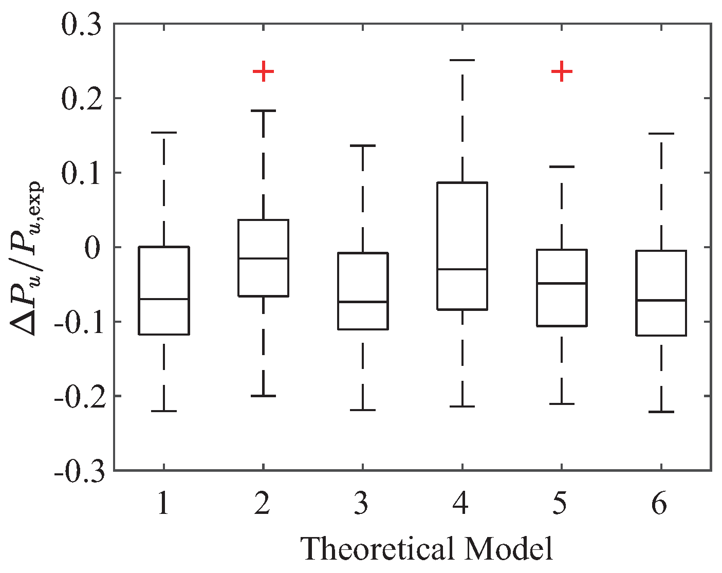
The results show that the ultimate axial load capacity of wall-like columns strengthened with FRP systems can be predicted with reasonably accuracy by the analytical models, except for the column specimens U11C and M01C of the experimental dataset produced by Tan. In both cases, the differences are due to the actual compressive strength of the concrete used to cast the tested columns; it is higher in M01C and lower in U11C with respect to the target value here used in the analysis (see Table 2). Quite accurate predictions of the axial load capacity are obtained using the analytical models proposed by Tan [20] and by Triantafillou et al. [31], that refer to similar formulation in the definition of the area ratio, and show errors closed in the interval of around (Figure 5). Moreover, quite conservative results are generally carried out using the analytical models proposed by Maalej et al. [27], Lam and Teng [10], and Vuggumudi et al. [32]. The more scattered results are obtained using the formulation proposed by Lignola et al. [30] that is very sensitive to the actual value of the effective lateral confining pressures assumed in the calculation. These results are confirmed by the statistics presented in Figure 6 and Table 3. In the former, box plots indicating the median values, and the lower and upper quartile of the errors distributions calculated using each simple model are represented. The latter provides the corresponding mean value and standard deviation of the percentage errors. The lowest mean values are found using the conventional formulation proposed by Tan [20] and the simplified approach proposed by Lignola et al. [30]. It can be justified by the transverse strain value of observed in their experimental results, and then assumed in the calibration of the analytical model.
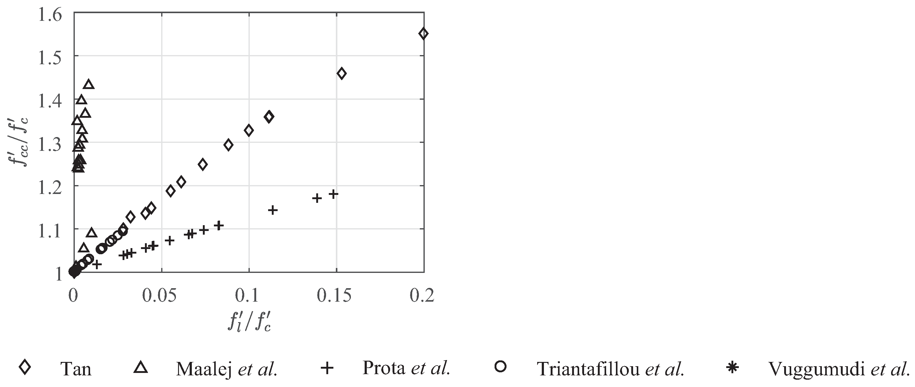
The relationship between the compressive strength ratio, , and the lateral confining pressure ratio, calculated for each simple model applied to the experimental data, are shown in Figure 7. It should be noted that the estimated strength increase is quite limited (up to 20%), for all the simple formulations, except for the model proposed by Tan [20] and by Maalej et al. [27] where increases up to and are, respectively, observed. In these last cases, applying the reduction factor of 0.85, as suggested by the authors, compressive strength ratios up to 31% and 27% are, respectively, obtained. These results are strongly related to the shape factor and to the confinement effectiveness coefficient adopted by each formulation. Only in the simple model proposed by Maalej et al. [27], within the confining pressure the contribution due to stirrups or internal links is explicitly considered.
The analytical models, presented in Section 3.1, were generally calibrated by each author starting from his own results. Consequently, the predictions of axial load capacity obtained applying the models to the complete dataset of Section 3.2 are in some cases inaccurate. Starting from this observation, a modified version of the model proposed by Triantafillou et al. [31] is proposed. As stated, the analytical models are based on the definition of the average strength of the confined concrete, to consider for the gross cross-sectional area. This parameter, as defined in Equation (2), depends on the estimation of lateral confining pressure exerted by the FRP wrapping, and from the definition of the confinement effectiveness coefficient, , and the shape factor coefficient, . In the case of wall-like columns, the confining stress path follows a “biaxial” compression behavior as stated by Lignola et al. [30] and then confirmed in the FEM analyses developed in the following Section 4.2. According to this assumption, in the modified version of the model of Triantafillou et al. [31] the value of the equivalent diameter D is assumed equal to the column width, b. On the other hand, the shape factor depends on the effectively confined area ratio and the aspect ratio . In the modified version of the model of Triantafillou et al. [31] the confinement effectiveness coefficient, , is assumed equal to 3.3 according to the model proposed by Lam and Teng [10], and the following expression for the shape factor is proposed:
where the effectively confined area ratio is calculated using the formula reported in Table 1 for the model of Triantafillou et al. [31]. This refers to the Models (b) and (c) of Figure 1, respectively, assumed for the cases of columns with and without internal links. Applying the modified model for the prediction of the axial load capacity of the dataset of strengthened columns of Table 2, an underestimation of on averaged is observed with a standard deviation of . These results point out that the proposed adjusted analytical model provides an improvement of the accuracy in the prediction of the ultimate axial load capacity of RC wall-like columns strengthened with FRP wrapping.
4.2. Numerical Results
Non-linear finite element analysis of the selected wall-like columns (see Table 4) under monotonic axial compression were carried out. The influence of FRP strengthening on the peak axial load capacity of the column and on the confinement of the concrete are presented and discussed. The load-carrying capacity of the columns is taken as the peak value reached during the analysis, generally observed at a vertical strain between and
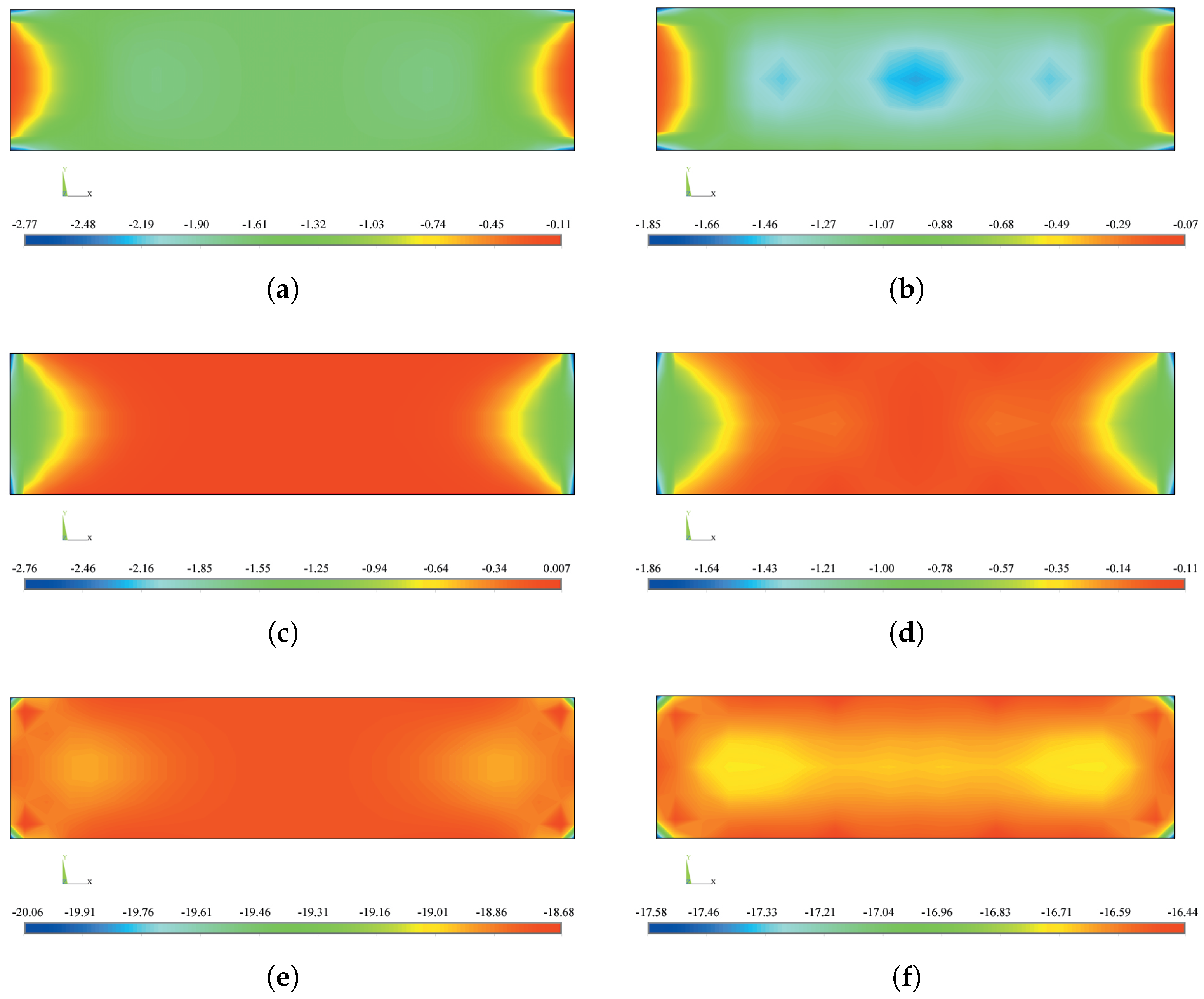
In Figure 8, the contour plots of the stresses acting in the cross-section at mid height of two columns at failure condition have been extracted. In particular, the confined concrete stresses in longitudinal direction x (parallel to the large side), in transverse direction y (parallel to the short side) of the cross-section, and in vertical direction z (parallel to the element axis), are represented for the II4 and S02C columns. In the former case, the values assumed by the normal stresses in the mid part of the cross-section point out that the first principal stress is parallel to the y direction and is close to zero (Figure 8c), the second principal stress is parallel to the x direction (Figure 8a) and the third principal stress is parallel to z direction (Figure 8e). The arch-shaped paths of the confining stresses (Figure 8a,c) rapidly changes in a straight distribution moving away from the corner. Moreover, the stress path in axial direction z in the column II4 shows a confined concrete pattern similar to the Model 2 represented in Figure 1b. These results are representative of a situation wherein only the corners of the columns act as anchor points and the internal links are ineffective in confining the concrete core. Therefore, it can be observed the typical “biaxial” stress state model that features a wall-like column strengthened with FRP systems.
On the other hand, the stress path in axial direction in the column S02C (Figure 8f) shows a concrete pattern similar to the Model 3 of Figure 1c, representative of a situation where the internal links are effective in confining the cross-section and the area of the confined concrete increases. Consequently, an increase of the confining effects due to the presence of internal stirrups is observed (see Figure 8b,d).
The numerical results on the axial load capacity of all the selected columns are summarized in Table 4, along with the ratio of numerical to experimental values. Overall, the agreement between test results and numerical prediction is more than satisfactory, with observed differences ranged between to . However, a higher difference is observed only for M01C strengthened column. In this case, the FEM model confirms the inaccuracy in the estimation of the axial load capacity already observed using the analytical models. In general, the results point out that FEM models give an accurate prediction of the axial load capacity for wall-like reinforced concrete columns strengthened with FRP systems. Moreover, the confinement effectiveness is again expressed in Table 4 in terms of compressive strength ratio, , whose values are closed in a range between 2.6% and 9.1%. To this aim, the confined concrete strength was estimated as the ratio between the compressive load carried by the confined concrete, , and the gross cross-sectional area of the wall-like column.
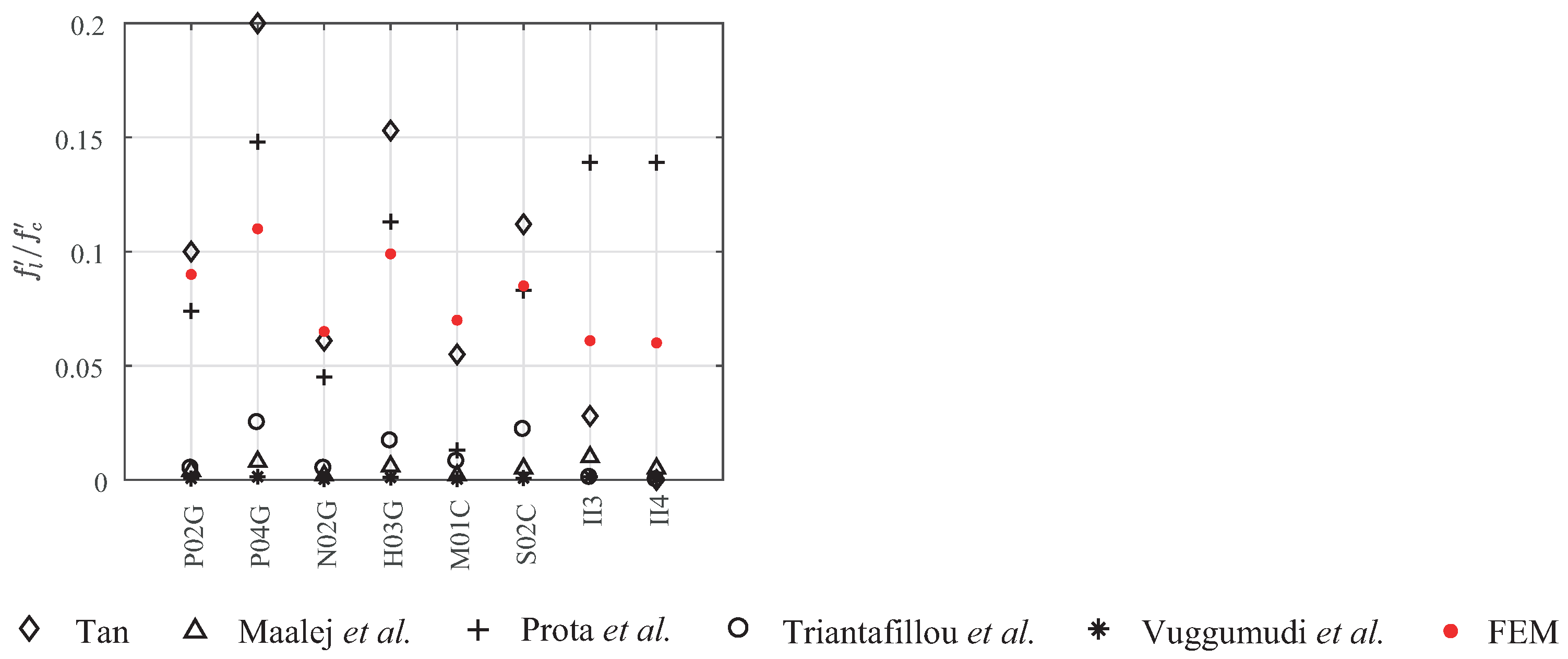
Furthermore, the comparison between the lateral confining pressure ratio, carried out by FEA and analytical models is shown in Figure 9. The results highlight that analytical models underestimate the effective lateral confining pressures, due to FRP strengthening except for the formulation proposed by Tan [20] and by Lignola et al. [22].
The results of the finite element analysis at peak of load-carrying capacity are used to calibrate a simple relation between the compressive strength ratio and the lateral confining pressure ratio . According to existing models [40], the axial compressive strength of FRP-confined concrete can be expressed as follows:
in which k is a function of the aspect ratio, , and of the effectively confined area ratio, , as discussed in Section 3.1.
The regression analysis on the FEA results leads to a value for the coefficient k equal to , showing that Equation (11) can be assumed linear for the tested columns. However, the use of Equation (11) requires the analytical assessment of the confining pressure ratio , i.e., an assumption about the value for the equivalent diameter, D, and for the FRP strain, . Taking into account the “biaxial” compression model and the experimental results, the former can be assumed equal to the column width, b, while the latter can be assumed equal to a conventional value [20,21,30]. Consequently, the k factor derived from the FEA results is modified accounting for the use of the conventional strain value instead of those obtained from the analysis (see Table 4). Thus, Equation (11) becomes:
in which is evaluated by Equation (7) assuming and instead of the ultimate FRP strain, .
Applying the model of Equation (12) to the dataset of columns in Table 2, the axial load capacity is underestimated of on average with a standard deviation of . These results point out that the simple model leads to conservative estimation of the axial load capacity. Thus, it can be considered very useful for a quick assessment of the load-carrying capacity of RC wall-like columns strengthened with FRP wrapping to be used in a preliminary design process.
5. Conclusions
The paper focuses on the effectiveness of simple analytical models and finite element models in the prediction of the confinement effects of a fiber reinforced polymer (FRP) system applied to rectangular reinforced concrete (RC) column with a high aspect ratio (wall-like).
First, the analytical solutions proposed in literature for the assessment of the axial load capacity are presented and discussed in a systematic way. In particular, the role played by different parameters on the confinement effects such as the cross-section aspect ratio, the corner radius, the effectiveness of internal links, and the different FRP strengthening systems are pointed out. For the purpose of a comparison analysis, a number of rectangular concrete wall-like columns strengthened with FRP systems, chosen between test data available in literature are selected. These experimental results cover wall-like columns having aspect ratios closed in the range between 2.6 and 4, strengthened with one or more layers of CFRP or GFRP placed in a transverse or longitudinal direction. The use of analytical models leads to reasonable predictions of the test results. It is shown that quite accurate predictions of the axial load capacity are obtained using the analytical models proposed by Tan [20] and by Triantafillou et al. [31], that are based on a more refined definition of the effectively confined area ratio, and show errors closed in the interval of around . Conservative results are generally carried out using the models proposed by Maalej et al. [27], Lam and Teng [10], and Vuggumudi et al. [32]. The more scattered results are obtained using the formulation proposed by Lignola et al. [30] that, although present the lower mean value, are very sensitive to the actual value of the effective lateral confining pressures assumed in the calculation. Starting from the discussion of the results obtained by application of the analytical models, a modified version of the model proposed by Triantafillou et al. [31] is presented and compared with experimental results. It is shown that the model provides an improvement of the accuracy in the prediction of the load-carrying capacity of the strengthened columns.
Then, non-linear finite element analysis of a number of the columns is also carried out in ANSYS. The numerical assessments of the axial load capacity of FRP strengthened wall-like columns are in very good agreement with the experimental results. Differences between experimental and numerical FEM results ranged between and are generally found. These results point out that FEM models give an accurate prediction of the axial load capacity for wall-like reinforced concrete columns strengthened with FRP systems, with the advantage to implicitly consider the contribution to confining pressure due to stirrups and internal links. Moreover, FEM results highlight less scattered values of the effective lateral confining pressures if compared with the corresponding ones assessed through analytical models. Finally, moving from the finite element analysis results, a simple model for the definition of the average axial compressive strength of the FRP-confined concrete is presented. The model was applied to the dataset of RC wall-like columns wrapped with FRP, considered here, to predict their axial load capacity. The comparison show that the model lead to slightly conservative and quite accurate results. Nevertheless, further analyses are needed to define the “effective” FRP lateral strain to be used in the model.
Author Contributions
The present study was conceptualized by A.M.A. The data are collected and analyzed by V.P. and F.R. Interpretation of the results and the manuscript writing were performed by A.M.A. Manuscript review and editing were concluded by F.R. and V.P. All authors have read and agreed to the published version of the manuscript.
Funding
This research received no external funding.
Institutional Review Board Statement
Not applicable.
Informed Consent Statement
Not applicable.
Data Availability Statement
Not applicable.
Conflicts of Interest
The authors declare no conflict of interest.
References
- Mirmiran, A.; Shahawy, M. Behavior of Concrete Columns Confined by Fiber Composites. J. Struct. Eng. 1997, 123, 583–590. [Google Scholar] [CrossRef]
- Spoelstra, M.R.; Monti, G. FRP-Confined Concrete Model. J. Compos. Constr. 1999, 3, 143–150. [Google Scholar] [CrossRef]
- Campione, G.; Miraglia, N. Strength and strain capacities of concrete compression members reinforced with FRP. Cem. Concr. Compos. 2003, 25, 31–41. [Google Scholar] [CrossRef]
- Matthys, S.; Toutanji, H.; Taerwe, L. Stress & Strain Behavior of Large-Scale Circular Columns Confined with FRP Composites. J. Struct. Eng. 2006, 132, 123–133. [Google Scholar]
- Wu, H.L.; Wang, Y.F.; Yu, L.; Li, X.R. Experimental and Computational Studies on High-Strength Concrete Circular Columns Confined by Aramid Fiber-Reinforced Polymer Sheets. J. Compos. Constr. 2009, 13, 125–134. [Google Scholar] [CrossRef]
- Mander, J.B.; Priestley, M.J.N.; Park, R. Theoretical Stress-Strain Model for Confined Concrete. J. Struct. Eng. 1988, 114, 1804–1826. [Google Scholar] [CrossRef] [Green Version]
- Mander, J.B.; Priestley, M.J.N.; Park, R. Observed Stress-Strain Behavior of Confined Concrete. J. Struct. Eng. 1988, 114, 1827–1849. [Google Scholar] [CrossRef]
- Mirmiran, A.; Shahawy, M.; Samaan, M.; Echary, H.E.; Mastrapa, J.C.; Pico, O. Effect of Column Parameters on FRP-Confined Concrete. J. Compos. Constr. 1998, 2, 175–185. [Google Scholar] [CrossRef]
- Rochette, P.; Labossiere, P. Axial Testing of Rectangular Column Models Confined with Composites. J. Compos. Constr. 2000, 4, 129–136. [Google Scholar] [CrossRef]
- Lam, L.; Teng, J.G. Design-Oriented Stress-Strain Model for FRP-Confined Concrete in Rectangular Columns. J. Reinf. Plast. Compos. 2003, 22, 1149–1186. [Google Scholar] [CrossRef]
- De Lorenzis, L.; Tepfers, R. Comparative study of models on confinement of concrete cylinders with fiber-reinforced polymer composites. J. Compos. Constr. 2003, 7, 219–237. [Google Scholar] [CrossRef]
- Al-Salloum, Y.A. Influence of edge sharpness on the strength of square concrete columns confined with FRP composite laminates. Compos. Part B Eng. 2007, 38, 640–650. [Google Scholar] [CrossRef]
- Wang, L.M.; Wu, Y.F. Effect of corner radius on the performance of CFRP-confined square concrete columns: Test. Eng. Struct. 2008, 30, 493–505. [Google Scholar] [CrossRef]
- Lignola, G.; Nardone, F.; Prota, A.; Manfredi, G. Analytical model for the effective strain in FRP-wrapped circular RC columns. Compos. Part B Eng. 2012, 43, 3208–3218. [Google Scholar] [CrossRef]
- ACI. Guide for the Design and Construction of Externally Bonded FRP Systems for Strengthening Concrete Structures (ACI 440. 2R-17); American Concrete Institute (ACI): Detroit, MI, USA, 2017. [Google Scholar]
- CNR. Guide for the Design and Construction of Externally Bounded FRP Systems for Strengthening Concrete Structures (CNR-DT 200 R1/2013); National Research Council (CNR): Washington, DC, USA, 2014. [Google Scholar]
- Rocca, S.; Galati, N.; Nanni, A. Review of Design Guidelines for FRP Confinement of Reinforced Concrete Columns of Noncircular Cross Sections. J. Compos. Constr. 2008, 12, 80–92. [Google Scholar] [CrossRef] [Green Version]
- Li, X.; Lu, J.; Ding, D.D.; Wang, W. Axial strength of FRP-confined rectangular RC columns with different cross-sectional aspect ratio. Mag. Concr. Res. 2017, 69, 1011–1026. [Google Scholar] [CrossRef]
- Tanwongsval, S.; Maalej, M.; Paramasivam, P. Strengthening of RC wall-like columns with FRP under sustained loading. Mater. Struct. 2003, 36, 282–290. [Google Scholar] [CrossRef]
- Tan, K.H. Strength Enhancement of Rectangular Reinforced Concrete Columns using Fiber-Reinforced Polymer. J. Compos. Constr. 2002, 6, 175–183. [Google Scholar] [CrossRef]
- Prota, A.; Manfredi, G.; Cosenza, E. Ultimate behavior of axially loaded RC wall-like columns confined with GFRP. Compos. Part B Eng. 2006, 37, 670–678. [Google Scholar] [CrossRef]
- Lignola, G.P.; Prota, A.; Manfredi, G.; Cosenza, E. Non-linear modeling of RC rectangular hollow piers confined with CFRP. Compos. Struct. 2009, 88, 56–64. [Google Scholar] [CrossRef]
- Alsayed, S.; Almusallam, T.; Ibrahim, S.; Al-Hazmi, N.; Al-Salloum, Y.; Abbas, H. Experimental and numerical investigation for compression response of CFRP strengthened shape modified wall-like RC column. Constr. Build. Mater. 2014, 63, 72–80. [Google Scholar] [CrossRef]
- Neale, K.; Demers, M.; DeVino, B.; Ho, N. Strengthening of wall-type reinforced concrete columns with fiber reinforced composite sheets. In Proceedings of the Fifth International Conference: Structural Failure Durability and Retrofitting, Singapore, 27–28 November 1997; Singapore Concrete Institute: Singapore, 1997; pp. 410–417. [Google Scholar]
- Chiew, S.; Lau, J.; Ho, N. Testing of wall-type reinforced concrete column strengthening with advanced composite materials. In Seminar on Strengthening and Upgrading Structures Using Advanced Composite Materials; Singapore Concrete Institute: Singapore, 1999; pp. 1–16. [Google Scholar]
- Wang, Y.; Restrepo, J. Investigation of concentrically loaded reinforced concrete columns confined with glass fiber-reinforced polymer jackets. ACI Struct. J. 2001, 98, 377–385. [Google Scholar]
- Maalej, M.; Tanwongsval, S.; Paramasivam, P. Modelling of rectangular RC columns strengthened with FRP. Cem. Concr. Compos. 2003, 25, 263–276. [Google Scholar] [CrossRef]
- Saatcioglu, M.; Razvi, S. Strength and Ductility of Confined Concrete. J. Struct. Eng. 1992, 118, 1590–1607. [Google Scholar] [CrossRef]
- Yalcin, C.; Saatcioglu, M. Inelastic analysis of reinforced concrete columns. Comput. Struct. 2000, 77, 539–555. [Google Scholar] [CrossRef]
- Lignola, G.P.; Prota, A.; Manfredi, G.; Cosenza, E. Modeling of RC wall-like columns FRP confinement. In Proceedings of the 1st Middle East Conference on Smart Monitoring, Assessment and Rehabilitation of Civil Structures SMAR 2011, Dubai, United Arab Emirates, 8–10 February 2011. [Google Scholar]
- Triantafillou, T.; Choutopoulou, E.; Fotaki, E.; Skorda, M.; Stathopoulou, M.; Karlos, K. FRP confinement of wall-like reinforced concrete columns. Mater. Struct. 2015, 49, 651–664. [Google Scholar] [CrossRef]
- Vuggumudi, S.; Alagusundaramoorthy, P. FRP Strengthened RC Rectangular Columns Under Combined Axial and Lateral Loading: Analytical Study. Structures 2018, 14, 88–94. [Google Scholar] [CrossRef]
- Vuggumudi, S.; Alagusundaramoorthy, P. Interaction diagrams for FRP strengthened RC rectangular columns with large aspect ratio. Constr. Build. Mater. 2018, 171, 187–196. [Google Scholar] [CrossRef]
- ACI440.2R. Guide for the Design and Construction of Externally Bonded FRP Systems for Strengthening Concrete Structures (ACI 440. 2R-08); American Concrete Institute (ACI): Detroit, MI, USA, 2008. [Google Scholar]
- Lam, L.; Teng, J.G. Design-oriented stress-strain model for FRP-confined concrete. Constr. Build. Mater. 2003, 17, 471–489. [Google Scholar] [CrossRef]
- Sheikh, S.A.; Uzumeri, S.M. Strength and ductility of tied concrete columns. J. Struct. Div. 1980, 106, 1079–1102. [Google Scholar] [CrossRef]
- William, K.J.; Warnke, E.D. (Eds.) Constitutive Model for the Triaxial Behaviour of Concrete; International Association for Bridge and Structural Engineering, Seminar on Concrete Structures Subjected to Triaxial Stresses: Bergamo, Italy, 1974; Volume 19, p. 174. [Google Scholar]
- Kent, D.C.; Park, R. Flexural members with confined concrete. J. Struct. Div. 1971, 97, 1969–1990. [Google Scholar] [CrossRef]
- Kohnke, P. ANSYS Theory Reference Manual; Ansys Inc.: Canonsburg, PA, USA, 2013. [Google Scholar]
- Lam, L.; Teng, J. Strength models for fiber-reinforced plastic-confined concrete. J. Struct. Eng. 2002, 128, 612–623. [Google Scholar] [CrossRef]
Figure 1.
Confinement effect due to transverse fiber: (a) Model 1, (b) Model 2, and (c) Model 3.

Figure 2.
Effective confinement area ratio vs. aspect ratio: (a) Lam and Teng [10], Vuggumudi et al. [32]; (b) Maalej et al. [27]; (c) Tan [20], Triantafillou et al. [31]; (–) Tan [20], Triantafillou et al. [31] for 1, 2, and 3 internal links, respectively.

Figure 3.
Numerical methodology flow-chart (a) and column II4 modeled in ANSYS (b).

Figure 4.
Performance of the analytical models in axial load capacity: scatter plot diagrams for the analytical model of (a) Lam and Teng [10]; (b) Tan [20]; (c) Maalej et al. [27]; (d) Lignola et al. [22]; (e) Triantafillou et al. [31]; (f) Vuggumudi et al. [32] (safe side down to straight line).

Figure 5.
Performance of the analytical models in axial load capacity: error plot diagrams for the analytical model of (a) Lam and Teng [10]; (b) Tan [20]; (c) Maalej et al. [27]; (d) Lignola et al. [22]; (e) Triantafillou et al. [31]; (f) Vuggumudi et al. [32].

Figure 6.
Performance of the analytical models in axial load capacity: error box plot diagram. (1) Lam and Teng [10]; (2) Tan [20]; (3) Maalej et al. [27]; (4) Lignola et al. [22]; (5) Triantafillou et al. [31]; (6) Vuggumudi et al. [32].

Figure 7.
Performance of the analytical models in assessment of confined concrete compressive strength vs. confinement ratio.
Figure 7.
Performance of the analytical models in assessment of confined concrete compressive strength vs. confinement ratio.

Figure 8.
Stresses contour plot of columns II4 and S02C at the peak axial force in longitudinal x direction (a,b), in transverse y direction (c,d), and in vertical z direction (e,f).
Figure 8.
Stresses contour plot of columns II4 and S02C at the peak axial force in longitudinal x direction (a,b), in transverse y direction (c,d), and in vertical z direction (e,f).

Figure 9.
Lateral confining pressure ratio : comparison between FEM and analytical models.


Table 1.
Parameters of the confined concrete analytical models in wall-like cross-sections.
| D | ||||
|---|---|---|---|---|
| Lam and Teng [10] | ||||
| Tan [20] | - | b | ||
| Maalej et al. [27] | ||||
| Lignola et al. [30] | − | 1 | − | b |
| Triantafillou et al. [31] | ||||
| Vuggumudi et al. [32] |
Table 2.
Existing test results of FRP-confined wall-like columns specimens.
| B | H | FRP | ||||||||||||
|---|---|---|---|---|---|---|---|---|---|---|---|---|---|---|
| Type | [%] | [%] | ||||||||||||
| Tan [20] | ||||||||||||||
| P00 * | 115 | 420 | - | 12.0 | 1068 | 500 | - | - | - | - | - | 1069 | - | - |
| P02G | 115 | 420 | 30 | 12.0 | 1068 | 500 | GFRP | 0.706 | - | - | 72,400 | 1181 | +10.5 | - |
| P04G | 115 | 420 | 30 | 12.0 | 1068 | 500 | GFRP | 1.412 | - | - | 72,400 | 1097 | +2.6 | - |
| K00 * | 115 | 420 | - | 20.0 | 1068 | 500 | - | - | - | - | - | 1318 | - | - |
| K02G | 115 | 420 | 30 | 20.0 | 1068 | 500 | GFRP | 2.00 | 1.00 | - | 26,100 | 1754 | +33.1 | - |
| N00 * | 115 | 420 | - | 20.0 | 1068 | 467 | - | - | - | - | - | 1566 | - | - |
| N02G | 115 | 420 | 30 | 20.0 | 1068 | 467 | GFRP | 2.00 | - | - | 26,100 | 1624 | +3.7 | - |
| H00 * | 115 | 420 | - | 12.0 | 1068 | 473 | - | - | - | - | - | 1040 | - | - |
| H03G | 115 | 420 | 30 | 12.0 | 1068 | 473 | GFRP | 3.00 | - | - | 26,100 | 1237 | +18.9 | - |
| M00 * | 115 | 420 | - | 16.0 | 1068 | 495 | - | - | - | - | - | 1430 | - | - |
| M01C | 115 | 420 | 30 | 16.0 | 1068 | 495 | CFRP | 0.165 | - | - | 228,000 | 1636 | +14.4 | - |
| M11C | 115 | 420 | 30 | 16.0 | 1068 | 495 | CFRP | 0.165 | 0.165 | - | 228,000 | 1450 | +1.4 | - |
| S00 * | 115 | 420 | - | 16.0 | 1068 | 495 | - | - | - | - | - | 1222 | - | - |
| S02C | 115 | 420 | 30 | 16.0 | 1068 | 495 | CFRP | 0.334 | - | - | 228,000 | 1372 | +12.3 | - |
| S12C | 115 | 420 | 30 | 16.0 | 1068 | 495 | CFRP | 0.22 | 0.11 | - | 228,000 | 1579 | +29.2 | - |
| S13C | 115 | 420 | 30 | 16.0 | 1068 | 467 | CFRP | 0.33 | 0.11 | - | 230,000 | 1586 | +29.8 | - |
| U00 * | 115 | 420 | - | 20.0 | 1068 | 467 | - | - | - | - | - | 1149 | - | - |
| U11C | 115 | 420 | 30 | 20.0 | 1068 | 467 | CFRP | 0.165 | 0.165 | - | 228,000 | 1297 | +12.9 | - |
| U12C | 115 | 420 | 30 | 20.0 | 1068 | 467 | CFRP | 0.330 | 0.165 | - | 228,000 | 1608 | +39.9 | - |
| Maalej et al. [27] | ||||||||||||||
| Control * | 115 | 420 | - | 32.4 | 1376 | 461 | - | - | - | - | - | 2067 | - | 0.28 |
| 2H2V-NL | 115 | 420 | 30 | 32.4 | 1376 | 461 | GFRP | 2.16 | 2.16 | 1860 | 26,130 | 2657 | +28.5 | 0.43 |
| Prota et al. [21] | ||||||||||||||
| V * | 115 | 420 | - | 15.0 | 1068 | 500 | - | - | - | - | - | 1035 | - | 0.30 |
| UN2 | 115 | 420 | 20 | 15.0 | 1068 | 500 | GFRP | 1.062 | 0.354 | - | 72,400 | 1374 | +32.7 | 0.55 |
| UN3 | 115 | 420 | 20 | 18.0 | 1068 | 500 | GFRP | 0.708 | 0.354 | - | 72,400 | 1575 | - | 0.44 |
| Triantafillou et al. [31] | ||||||||||||||
| C3 * | 150 | 450 | - | 18.0 | 679 | 570 | - | - | - | - | - | 1149 | - | 0.30 |
| II3 | 150 | 450 | 20 | 18.0 | 679 | 570 | CFRP | 2.00 | - | 1046 | 93,700 | 1601 | +39.3 | 1.53 |
| C4 * | 150 | 600 | - | 18.0 | 905 | 570 | - | - | - | - | - | 1509 | - | 0.44 |
| II4 | 150 | 600 | 20 | 18.0 | 905 | 570 | CFRP | 2.00 | - | 1046 | 93,700 | 1908 | +26.4 | 1.47 |
| Vuggumudi et al. [32] | ||||||||||||||
| CCA1 * | 230 | 600 | - | 20.0 | 2945 | 415 | - | - | - | - | - | 3334 | - | 0.65 |
| RCA2 | 230 | 600 | - | 20.0 | 2945 | 415 | CFRP | 1.2 | - | 602 | 67,000 | 4609 | +38.2 | 0.79 |
* Reference Columns.
Table 3.
Performance of the analytical models in axial load capacity: mean value and standard deviation of the percentage error.
Table 3.
Performance of the analytical models in axial load capacity: mean value and standard deviation of the percentage error.
| Model | Mean (%) | St. Dev. (%) |
|---|---|---|
| Lam and Teng [10] | ||
| Tan [20] | ||
| Maalej et al. [27] | ||
| Lignola et al. [22] | ||
| Triantafillou et al. [31] | ||
| Vuggumudi et al. [32] |
Table 4.
Performance of the numerical FEM models in axial load capacity assessment.
| Column | (kN) | (kN) | (%) | |||
|---|---|---|---|---|---|---|
| M01C | 1636 | 1329 | ||||
| S02C | 1372 | 1338 | ||||
| P02G | 1181 | 1143 | ||||
| P04G | 1097 | 1147 | ||||
| N02G | 1624 | 1498 | ||||
| H03G | 1237 | 1115 | ||||
| II3 | 1601 | 1604 | ||||
| II4 | 1908 | 2143 |
Publisher’s Note: MDPI stays neutral with regard to jurisdictional claims in published maps and institutional affiliations. |
© 2021 by the authors. Licensee MDPI, Basel, Switzerland. This article is an open access article distributed under the terms and conditions of the Creative Commons Attribution (CC BY) license (https://creativecommons.org/licenses/by/4.0/).
Share and Cite
MDPI and ACS Style
Avossa, A.M.; Picozzi, V.; Ricciardelli, F. Load-Carrying Capacity of Compressed Wall-Like RC Columns Strengthened with FRP. Buildings 2021, 11, 285. https://0-doi-org.brum.beds.ac.uk/10.3390/buildings11070285
AMA Style
Avossa AM, Picozzi V, Ricciardelli F. Load-Carrying Capacity of Compressed Wall-Like RC Columns Strengthened with FRP. Buildings. 2021; 11(7):285. https://0-doi-org.brum.beds.ac.uk/10.3390/buildings11070285
Chicago/Turabian StyleAvossa, Alberto Maria, Vincenzo Picozzi, and Francesco Ricciardelli. 2021. "Load-Carrying Capacity of Compressed Wall-Like RC Columns Strengthened with FRP" Buildings 11, no. 7: 285. https://0-doi-org.brum.beds.ac.uk/10.3390/buildings11070285
Note that from the first issue of 2016, this journal uses article numbers instead of page numbers. See further details here.