
Stress Intensity Factor of Reinforced Concrete Beams in Bending

 ,
,  , and
, and 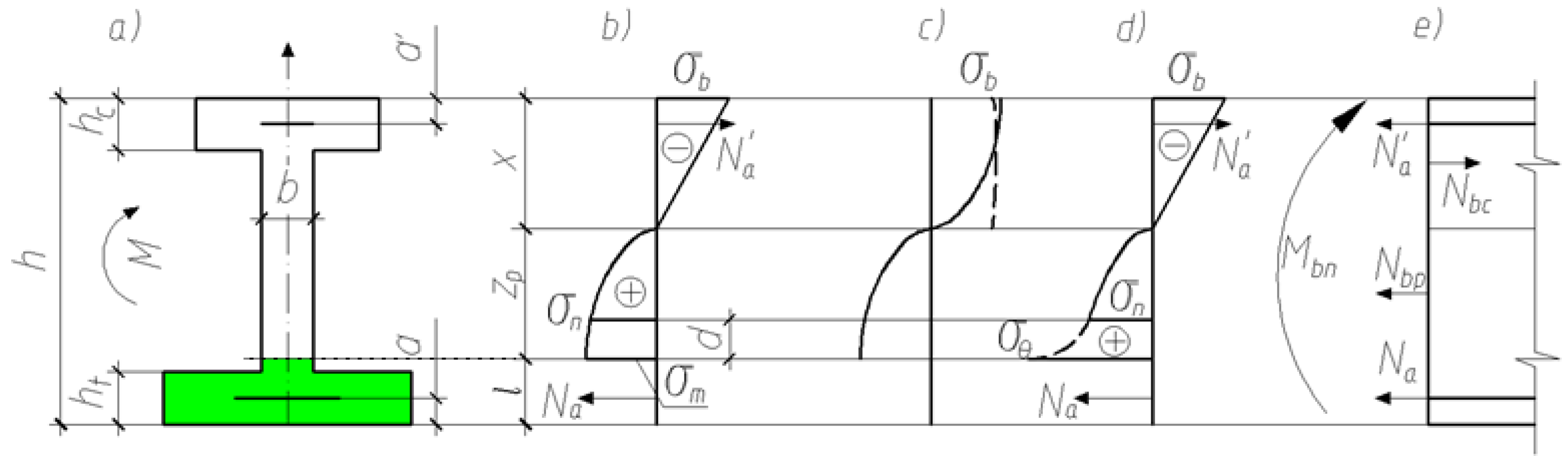
Abstract
:1. Introduction
2. Methods
2.1. Analytical Method
2.2. Numerical Calculation of the Stress Intensity Factor
3. Results and Discussion
3.1. Analytical Determination of the Stress State
- (i)
- The equilibrium equation of the beam’s cut-off part in the form of the sum of the projection of forces on the beam axis is as follows:
- (ii)
- The equilibrium equation in the form of the sum of the moments of all forces relative to the central axis of concrete has the form
- -
- finding the dimensionless moment from the Equation (16);
- -
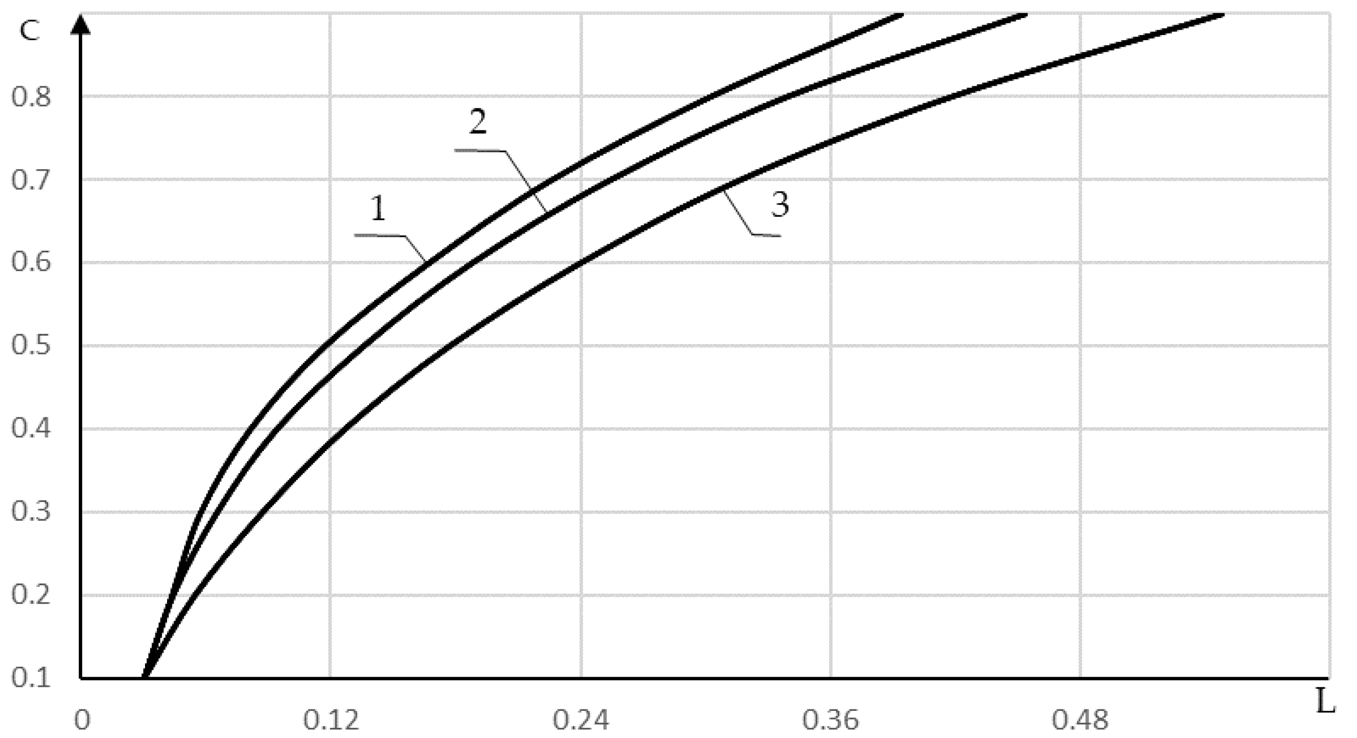
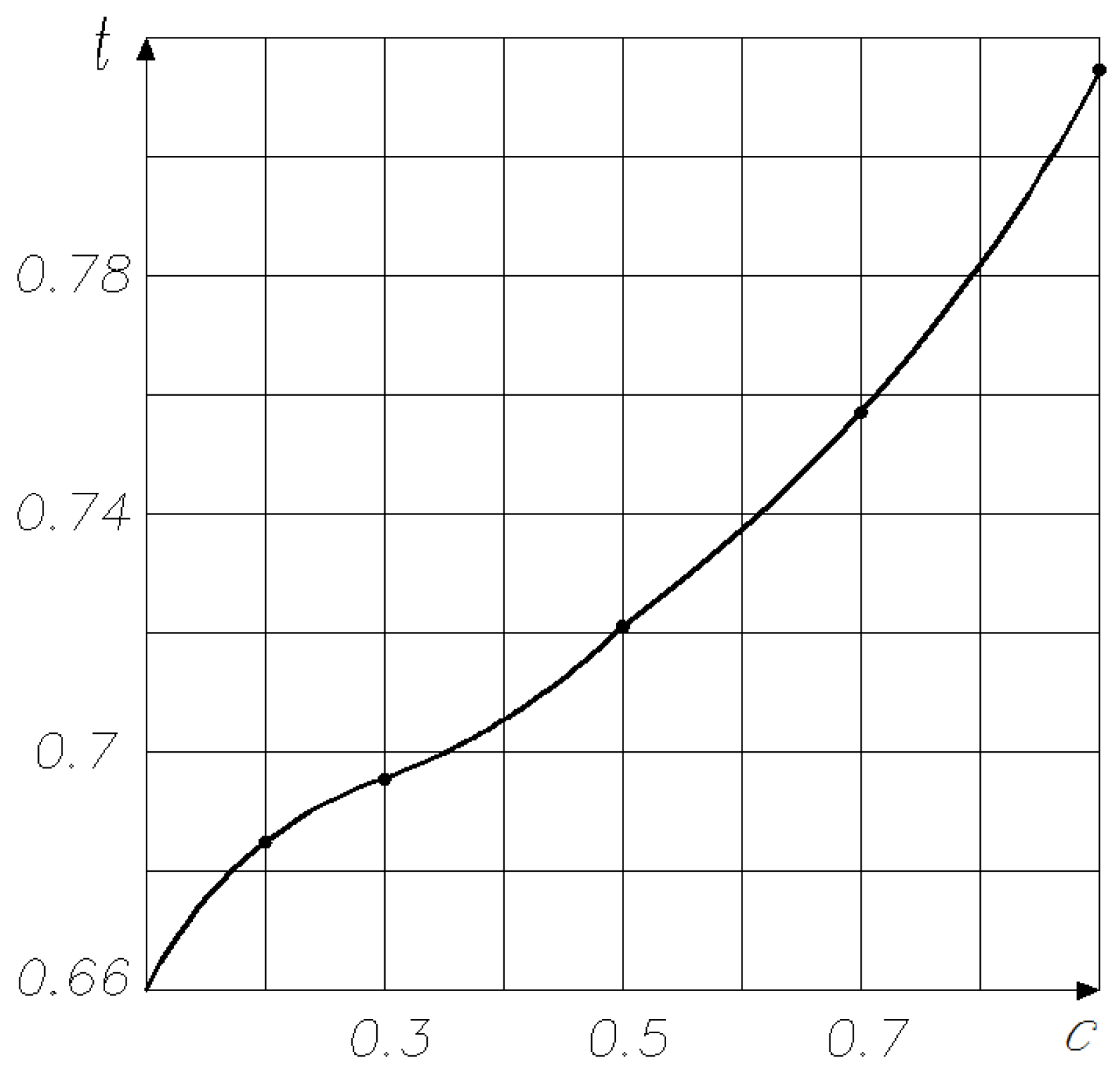
- finding the dimensionless stress at the crack tip from the dimensionless load parameter at a known relative crack length (Figure 3);
- -
- finding from the Equation (15);
- -
- and then we determine from using (12).
3.2. Determination of the Stress Intensity Factor
3.3. Calculation Example
3.4. Numerical Calculation
4. Conclusions
- The analytical method for determining the stress intensity factor (SIF) with an initial and growing crack in bent reinforced concrete beams is proposed. The method is based on the assumption that the size of the stress concentration zone at the crack tip is determined by the equality of the nominal and local stresses at the end of this zone (Figure 1d). The method determines the value of the external moment starting from which the crack length increases.
- The results obtained make it possible to assess the bearing capacity of reinforced concrete beams with a crack and assess the crack resistance of the beam by the force criterion of fracture mechanics. The analytical calculation method is valid for beams of arbitrary cross-sections, but explicit dependencies and numerical results are given for rectangular cross-section beams, which are most often used. Numerical calculation of SIF is recommended for non-growing initial cracks or a low-stress level if the maximum compressive stresses in concrete do not exceed 70% of the ultimate compressive strength.
- The same problem is solved in a three-dimensional formulation by the FE method, considering the stress field’s peculiarities at the crack tip. The calculation results coincide with the analytical solutions.
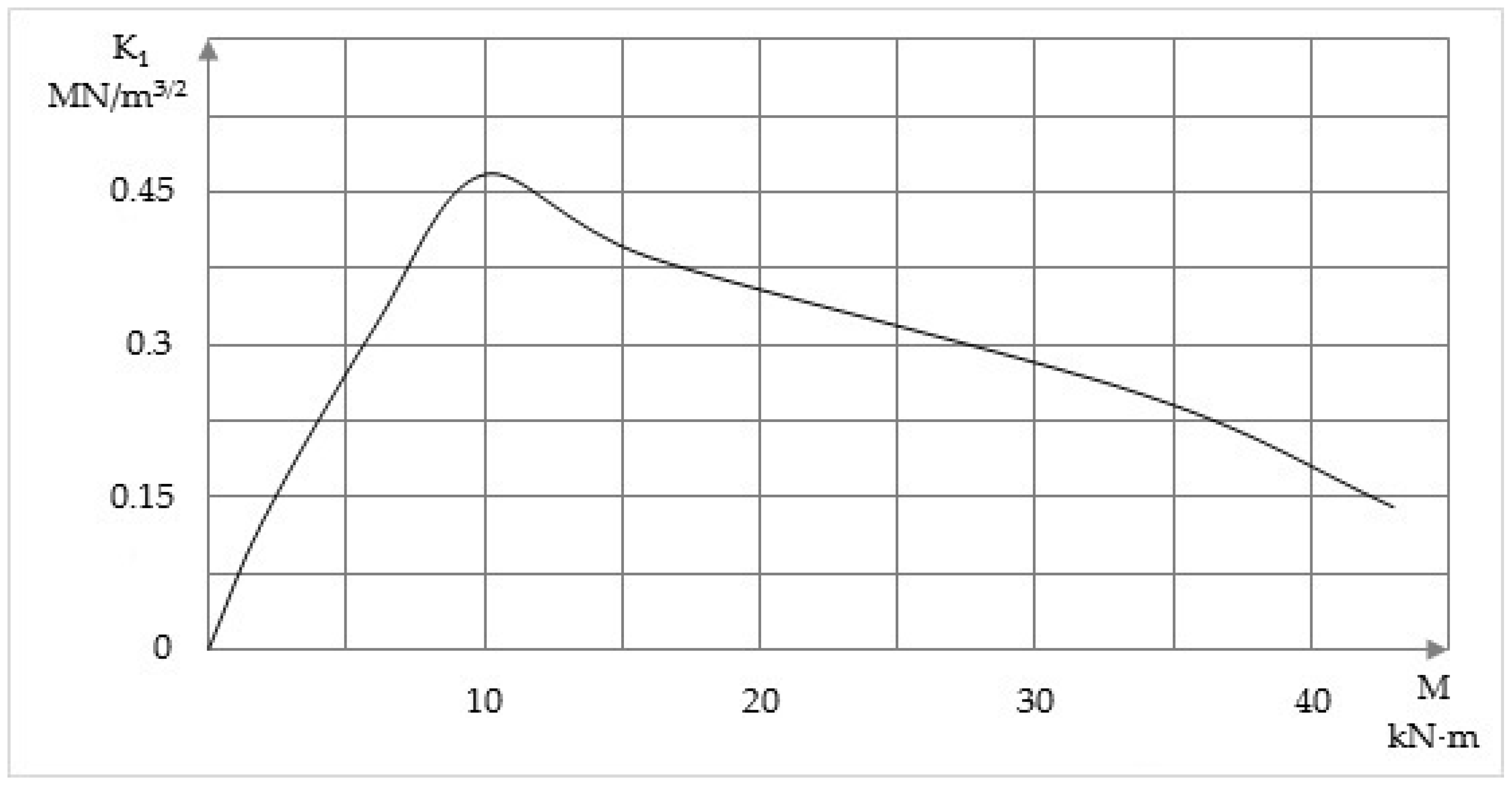
- It was found that SIF decreases with increasing crack length in a reinforced concrete beam. Consequently, unstable crack propagation reduces its bearing capacity but does not lead to rapid beam destruction.
Author Contributions
Funding
Institutional Review Board Statement
Informed Consent Statement
Conflicts of Interest
References
- Kodysh, E.N.; Nikitin, I.K.; Trekin, N.N. Calculation of Reinforced Concrete Structures from Heavy Concrete for Strength, Crack Resistance and Deformation; Association of Civil Engineering Universities: Moscow, Russia, 2011; ISBN 978-5-93093-723-7. [Google Scholar]
- Korgin, A.V.; Zeyd, K.L.Z.; Ermakov, V.A. Healthmonitoring of building constructions with crack-like defects. Vestn. MGSU 2013, 77–83. [Google Scholar] [CrossRef]
- Ckhum, A. Experimental investigation of deflected mode of the rienforced concrete beams with organized cracks under long-term loading. Vestn. SibADI 2018, 15, 606–616. [Google Scholar] [CrossRef]
- Mitasov, V.M.; Statsenko, N.V.; Sametov, F.K.; Kurbonov, A.M. Crack strength of hollow core slabs: Experimental research. Russ. Automob. Highw. Ind. J. 2019, 16, 366–377. [Google Scholar] [CrossRef]
- Fantilli, A.P.; Chiaia, B. Golden Ratio in the Crack Pattern of Reinforced Concrete Structures. J. Eng. Mech. 2013, 139, 1178–1184. [Google Scholar] [CrossRef]
- Bykov, A.A.; Matveenko, V.P.; Shardakov, I.N.; Shestakov, A.P. Shock wave method for monitoring crack repair processes in reinforced concrete structures. Mech. Solids 2017, 52, 378–383. [Google Scholar] [CrossRef]
- Chernin, L.; Val, D.V. Prediction of corrosion-induced cover cracking in reinforced concrete structures. Constr. Build. Mater. 2011, 25, 1854–1869. [Google Scholar] [CrossRef]
- Hsu, T.T.C. Unified Theory of Reinforced Concrete; CRC Press: Boca Raton, FL, USA, 2017; ISBN 9781351406109. [Google Scholar]
- Bazant, Z.P. Mechanics of Fracture and Progressive Cracking in Concrete Structures; Martinus Nijhoff Publishers: Leiden, Belgium, 1985; ISBN 9024729602. [Google Scholar]
- Demyanov, A.I.; Naumov, N.V.; Kolchunov, V.I. The calculating method of crack resistance and rigidity of reinforced concrete composite constructions under the action torsion with bending. Build. Reconstr. 2018, 3–19. [Google Scholar] [CrossRef] [Green Version]
- Nuguzhinov, Z.; Vatin, N.; Bakirov, Z.; Khabidolda, O.; Zholmagambetov, S.; Kurokhtina, I. Stress-strain state of bending reinforced beams with cracks. Mag. Civ. Eng. 2020, 97. [Google Scholar] [CrossRef]
- Tay, Y.W.D.; Qian, Y.; Tan, M.J. Printability region for 3D concrete printing using slump and slump flow test. Compos. Part B Eng. 2019, 174, 106968. [Google Scholar] [CrossRef]
- Kaklauskas, G. Crack Model for RC Members Based on Compatibility of Stress-Transfer and Mean-Strain Approaches. J. Struct. Eng. 2017, 143, 04017105. [Google Scholar] [CrossRef]
- Ma, F.J.; Kwan, A.K.H. Crack width analysis of reinforced concrete members under flexure by finite element method and crack queuing algorithm. Eng. Struct. 2015, 105, 209–219. [Google Scholar] [CrossRef]
- Kwan, A.K.H.; Ma, F.J. Crack width analysis of reinforced concrete under direct tension by finite element method and crack queuing algorithm. Eng. Struct. 2016, 126, 618–627. [Google Scholar] [CrossRef]
- Barre, F.; Bisch, P.; Chauvel, D.; Cortade, J.; Coste, J.F.; Dubois, J.P.; Erlicher, S.; Gallitre, E.; Labbé, P.; Mazars, J.; et al. Control of Cracking in Reinforced Concrete Structures; Wiley Blackwell: Hoboken, NJ, USA, 2016; ISBN 9781119347088. [Google Scholar]
- Oliver-Leblond, C.; Delaplace, A.; Ragueneau, F. Modelling of three-dimensional crack patterns in deep reinforced concrete structures. Eng. Struct. 2015, 83, 176–186. [Google Scholar] [CrossRef]
- Shiu, W.; Donzé, F.V.; Daudeville, L. Discrete element modelling of missile impacts on a reinforced concrete target. Int. J. Comput. Appl. Technol. 2009, 34, 33–41. [Google Scholar] [CrossRef]
- Yang, S.T.; Li, K.F.; Li, C.Q. Numerical determination of concrete crack width for corrosion-affected concrete structures. Comput. Struct. 2018, 207, 75–82. [Google Scholar] [CrossRef] [Green Version]
- Iakovenko, I.A.; Kolchunov, V.I. The development of fracture mechanics hypotheses applicable to the calculation of reinforced concrete structures for the second group of limit states. J. Appl. Eng. Sci. 2017, 15, 371–380. [Google Scholar] [CrossRef] [Green Version]
- García-Álvarez, V.O.; Gettu, R.; Carol, I. Analysis of mixed-mode fracture in concrete using interface elements and a cohesive crack model. Sadhana 2012, 37, 187–205. [Google Scholar] [CrossRef] [Green Version]
- Anderson, T.L. Fracture Mechanics: Fundamentals and Applications, 4th ed.; CRC Press: Boca Raton, FL, USA, 2017; ISBN 9781498728133. [Google Scholar]
- Malipatil, K.M.; Itti, S.V. Stress Intensity Factor and Damage Index of Reinforced Concrete Beam. In Fatigue, Durability, and Fracture Mechanics; Lecture Notes in Mechanical Engineering; Springer Science and Business Media Deutschland GmbH: Berlin/Heidelberg, Germany, 2021; pp. 305–316. [Google Scholar]
- Kosior-Kazberuk, M.; Berkowski, P. Fracture Mechanics Parameters of Fine Grained Concrete with Polypropylene Fibres. In Proceedings of the Procedia Engineering; Elsevier Ltd.: Amsterdam, The Netherlands, 2016; Volume 161, pp. 157–162. [Google Scholar]
- Wang, Z.; Gou, J.; Gao, D. Experimental study on the fracture parameters of concrete. Materials 2021, 14, 129. [Google Scholar] [CrossRef]
- Gomes, R.F.; Dias, D.P.; Silva, F.d.A. Determination of the fracture parameters of steel fiber-reinforced geopolymer concrete. Theor. Appl. Fract. Mech. 2020, 107, 102568. [Google Scholar] [CrossRef]
- Jenq, Y.; Shah, S.P. Two Parameter Fracture Model for Concrete. J. Eng. Mech. 1985, 111, 1227–1241. [Google Scholar] [CrossRef]
- Carpinteri, A.; Spagnoli, A. A fractal analysis of size effect on fatigue crack growth. Int. J. Fatigue 2004, 26, 125–133. [Google Scholar] [CrossRef]
- Kolchunov, V.I.; Dem’yanov, A.I. The modeling method of discrete cracks in reinforced concrete under the torsion with bending. Mag. Civ. Eng. 2018, 81, 160–173. [Google Scholar] [CrossRef]
- Karpenko, N.I. General Models of Reinforced Concrete Mechanics; Stroyizdat: Moscow, Russia, 1996. [Google Scholar]
- Nuguzhinov, Z.S. The Theory of Calculation of Damaged Reinforced Concrete Structures; Publishing House of KSTU: Karaganda, Kazakhstan, 2012. [Google Scholar]
- Elliott, K.S. Precast Concrete Structures, 2nd ed.; CRC Press: Boca Raton, FL, USA, 2016; ISBN 9781498724005. [Google Scholar]
- Wittmann, F.H.; Zaytsev, Y.V. Application of fracture mechanics to investigate durability of concrete under load. In Proceedings of the 8th International Conference on Fracture Mechanics of Concrete and Concrete Structures, FraMCoS 2013, Toledo, Spain, 10–14 March 2013; pp. 50–56. [Google Scholar]
- Ercolani, G.D.; Ortega, N.F.; Felix, D.H. Diagnosis of failures in concrete structures. In Concrete and Concrete Structures: A Review and Directions for Research; Nova Science Publishers, Inc.: New York, NY, USA, 2017; pp. 43–84. ISBN 9781536127966. [Google Scholar]
- Nuguzhinov, Z.S.; Bakirov, Z.B.; Yu Kurokhtin, A.; Khabidolda, O.; Nuguzhinova, A. Assessment of Bending Reinforced Concrete Beams Crack Resistance. IOP Conf. Ser. Mater. Sci. Eng. 2019, 690, 012002. [Google Scholar] [CrossRef]


Publisher’s Note: MDPI stays neutral with regard to jurisdictional claims in published maps and institutional affiliations. |
© 2021 by the authors. Licensee MDPI, Basel, Switzerland. This article is an open access article distributed under the terms and conditions of the Creative Commons Attribution (CC BY) license (https://creativecommons.org/licenses/by/4.0/).
Share and Cite
Nuguzhinov, Z.S.; Bakirov, Z.B.; Vatin, N.I.; Bakirov, M.Z.; Kurokhtina, I.A.; Tokanov, D.T.; Khabidolda, O. Stress Intensity Factor of Reinforced Concrete Beams in Bending. Buildings 2021, 11, 287. https://0-doi-org.brum.beds.ac.uk/10.3390/buildings11070287
Nuguzhinov ZS, Bakirov ZB, Vatin NI, Bakirov MZ, Kurokhtina IA, Tokanov DT, Khabidolda O. Stress Intensity Factor of Reinforced Concrete Beams in Bending. Buildings. 2021; 11(7):287. https://0-doi-org.brum.beds.ac.uk/10.3390/buildings11070287
Chicago/Turabian StyleNuguzhinov, Zhmagul Smagulovich, Zhetpisbay Bakirovich Bakirov, Nikolai Ivanovich Vatin, Madi Zhetpisbaevich Bakirov, Irina Alekseevna Kurokhtina, Daniyar Tokanovich Tokanov, and Omirkhan Khabidolda. 2021. "Stress Intensity Factor of Reinforced Concrete Beams in Bending" Buildings 11, no. 7: 287. https://0-doi-org.brum.beds.ac.uk/10.3390/buildings11070287