
Prospects of Developing Prefabricated Masonry Walling Systems in Australia
by
 , , ,
, , ,
Julian Thamboo
1,
Tatheer Zahra
2,
Satheeskumar Navaratnam
3,* ,
,
Mohammad Asad
2 and
Keerthan Poologanathan
4 1
Department of Civil Engineering, South Eastern University of Sri Lanka, Oluvil 32360, Sri Lanka
2
School of Civil Engineering and Built Environment, Queensland University of Technology, Brisbane 4000, Australia
3
School of Engineering, RMIT University, Melbourne 3000, Australia
4
Faculty of Engineering and Environment, Northumbria University, Newcastle upon Tyne NE1 8ST, UK
*
Author to whom correspondence should be addressed.
Buildings 2021, 11(7), 294; https://0-doi-org.brum.beds.ac.uk/10.3390/buildings11070294
Submission received: 3 June 2021
/
Revised: 28 June 2021
/
Accepted: 2 July 2021
/
Published: 6 July 2021
(This article belongs to the Section Building Energy, Physics, Environment, and Systems)
Abstract
:Prefabrication has been shown to be an effective way of construction in the modern-day context. Although much progress has been made in developing reinforced concrete (RC), timber and steel prefabricated elements/structures, prefabrication of masonry walling systems has received limited attention in the past. Conventional masonry construction is labour-intensive and time-consuming; therefore, prefabrication can be an effective solution to accelerate the masonry construction to make it more cost-effective. Therefore, in this paper, an attempt has been made to evaluate the effectiveness of prefabricated masonry systems (PMS) in terms of their structural characteristics and sustainability perspectives in an Australian context. Subsequently, the available studies related to PMS and the prospects of developing prefabricated masonry walling systems were appraised and reported. In order to assess the applicability of PMS, a case study was carried out by designing four types of prospective prefabricated masonry walling systems for a typical housing unit in Australia. It was shown that the reinforced (RM), post-tensioned (PT) and thin layered mortared (TLM) masonry systems are better suited for prefabrication. Later, in order to assess the sustainability of the considered masonry walling systems, life cycle energy analyses were carried using the Environmental Performance in Construction (EPIC) database. It was found that there can be nearly 30% and 15% savings, respectively, in terms of energy saving and CO2 emissions in prefabricated construction than the conventional masonry construction. Finally, the prospects of developing PMS and the need for future research studies on these systems are highlighted.
1. Introduction
Masonry is one of the oldest construction materials in the world; nevertheless, it is still a preferred material for construction due to its simple construction method, relatively good loadbearing capacity, better fire and acoustic properties and aesthetic appeal. However, the conventional masonry construction method is slow and labour intensive; thus, the masonry construction industries at present are dealing with challenges against the depleting skilled labour force, time bound economy driven nature of modern construction and new-generation materials/walling systems. Subsequently, many alternative masonry construction systems were developed to meet the demands and reduce the labour intensiveness of masonry construction. These alternative masonry construction techniques include larger and lighter units (e.g., Aerated Autoclaved Concrete units), thin layer mortaring (TLM) and mortarless masonry systems [1,2,3]. Further, to improve the structural capacities and ductility of the masonry, core grouting techniques, reinforcing, prestressing and surface rendering with composites have been incorporated in the past [4,5,6,7].
On the other hand, increasing population, depleting skill labourers and thereby rising labour costs, and the requirement for rapid construction of infrastructures have encouraged the embrace of prefabricated or modular construction techniques [8,9,10,11]. In addition, damages to the infrastructures due to ever increasing disasters, particularly in Australia, such as bushfires, floods and cyclones, demand rapid reconstruction and favour prefabricated construction techniques. The prefabricated construction systems comprise modular panels that are typically manufactured off-site in a quality-controlled environment with architectural finishes and services. These modules are then transported and installed on-site as load-resisting structural elements of the building [12]. Prefabrication enables a speedy construction, high volume output and consistent quality at a competitive cost. It also provides environmental benefits, such as the reduction of construction wastes, CO2 emissions, and less constraints at the construction site by minimising on-site waste, noise and dust [13,14]. These advantages drive many countries to adopt prefabricated building systems and Australia is no exception to this scenario [15,16]. Subsequently, in Australia, the prefabricated construction system has been promoted as one of the eight key “visions” for improving the efficiency and performance of the Australian construction industry in their Construction vision 2020 [17].
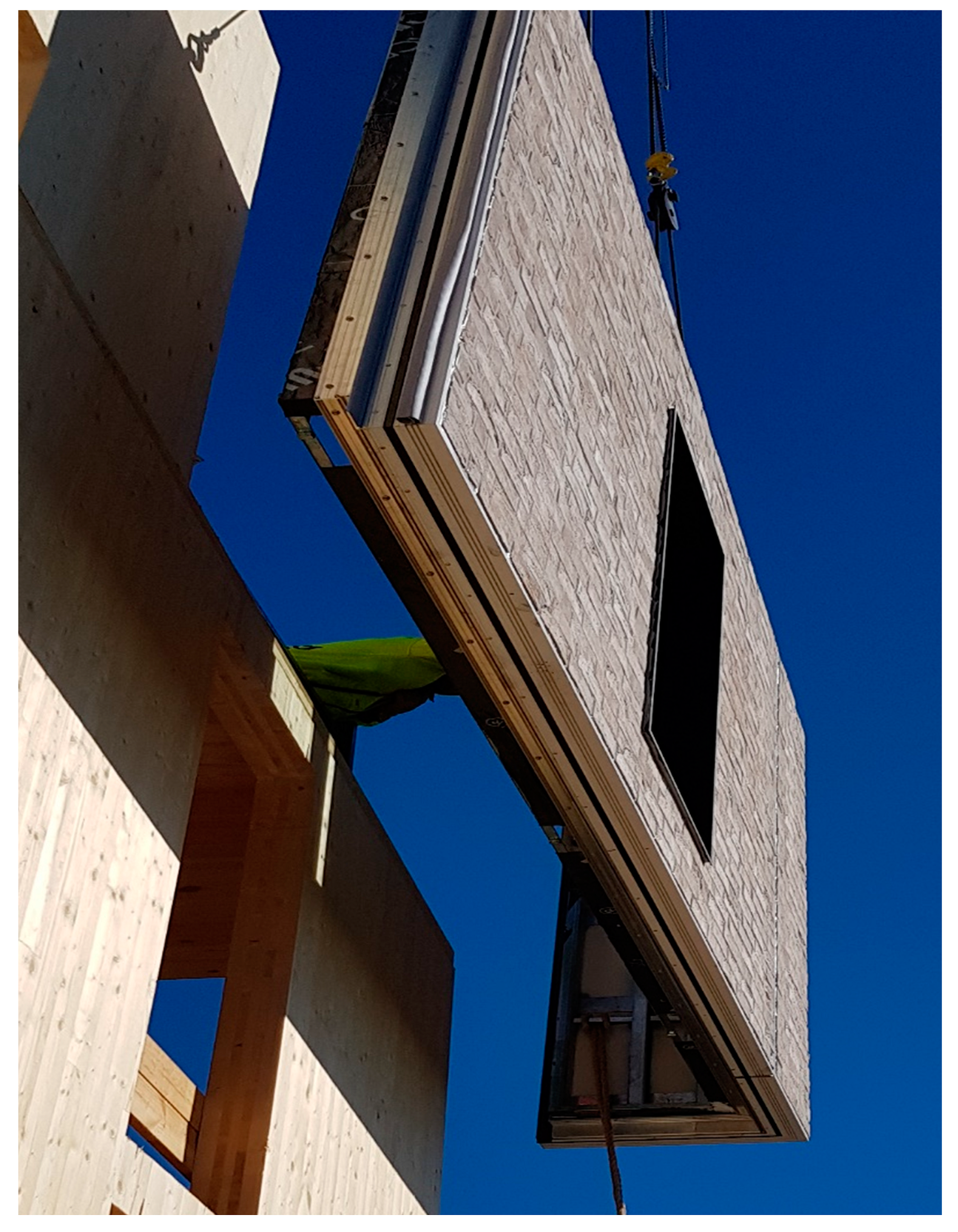
Accordingly, concrete, steel and timber industries have made substantial progress in establishing prefabricated systems and their developments are well supported by systematic research studies [18,19,20,21,22,23,24]. Subsequently, plenty of studies been carried out to assess the performance of concrete, steel and wood based prefabricated construction systems [25,26,27,28,29,30]. In relative terms, attention given to develop prefabricated masonry walling systems is minimal. While various forms of prefabricated masonry systems (PMS) were developed in many parts of the world with adequate design requirements, these have not yet reached the criteria required for widespread mass production [31]. Figure 1 shows a prefabricated masonry façade walling panel. The reasons for limited development in establishing fully-fledged PMS varies across different countries. The economy-driven criteria of selecting a structural system primarily play a significant role in developing prefabricated masonry. Further, limited awareness among the architects and engineers on the performance, benefits, method and knowledge of PMS also restricts its extensive application.
Moreover, systematic research studies to investigate the structural performance of PMS are limited [32,33,34,35,36,37]. It can be implied that most of the developed PMS in the past were proprietary in nature with insufficient details provided on materials, structural design, fabrication and erection methods. Any PMS with connecting components should be able to withstand loads induced by the occupancy of the structure as well as the external loads exerted due to wind, fire and earthquake. In this regard, minimal research studies were deliberated in the past, which is a major hindrance in confident uptake of PMS by the industry.
Furthermore, the life cycle energy and life cycle cost (LCE and LCC) of the PMS are not well accounted to highlight the benefits of the prefabricated masonry to the developers and end users. Comparing LCE and LCC of prefabricated concrete, steel and timber systems with their corresponding conventional construction methods show that they are more or less similar. The prefabricated systems are considered superior in the individual aspects of the life cycle analyses, such as construction time, wastage and reusability [38,39]. Samani et al. [40] analysed the LCC of a prefabricated fibre reinforced composite walling system and conventional masonry buildings in the US context. The results showed that the composite prefabricated walling systems consumed higher maintenance and lower demolition cost compared to the conventional masonry. It can be hypothesised that the PMS would consume less maintenance cost and energy than other prefabricated systems due to the good inherent thermal and acoustic insulation characteristics. Therefore, the overall LCE and LCC of the prefabricated masonry can be less than the other prefabricated systems.
In summary, the development and practice of prefabricated masonry construction are not well taken by the industry due to limited research and industrial manufacturing facilities. Although the prefabricated masonry can be an attractive solution to accelerate the labour intensive conventional masonry construction, especially for the low-rise buildings, the uptake is hindered by a lack of understanding of the structural and sustainable characteristics of PMS. Therefore, in this paper, an attempt has been made to critically analyse the status quo of the PMS with their future prospects in the Australian context. Initially, the PMS developed in the past are outlined in terms of their construction type and structural performance. Thereafter, the available design guidelines and erection methodologies of prefabricated systems have been applied to design a typical Australian housing unit with various kinds of PMSs as a case study. Further, for the selected masonry prefabricated masonry walling systems, LCC and LCE were analysed to verify the economic benefit or limitation of the system.
2. Review of the Existing PMS
In order to comprehend the characteristics of prefabricated masonry, some of the PMS reported in the available literature were reviewed and outlined in this section. It must be mentioned that there are some patented PMS which were not evolved into successful or widely used applications, and therefore are not considered in this review. Similarly, prefabricated composite or reinforced concrete walling systems, where pre-cut masonry slips were provided to give masonry a façade appearance [41], are not considered in this review as these are not truly a masonry system which should consist of discrete bricks/blocks and mortar joints. It is commonly understood that the prefabrication of conventional unreinforced masonry system is not feasible, as the bond between the units (bricks or blocks) and conventional cement mortar is relatively weak, and thus would crack during the transportation and erection stages. To encounter this limitation, mainly the reinforced, post-tensioned and high bond strength masonry walling systems were adopted for prefabrication [42]. Accordingly, some of those systems are briefly summarised and discussed in this section for the prospect of developing prefabricated masonry in the Australian context.
2.1. Reinforced Masonry
The reinforced masonry (RM) walls are preferred over unreinforced masonry where substantial lateral load resistance is required due to seismic and wind load effects. The introduction of reinforcement in masonry improves the tensile resistance and ductility of the masonry. The reinforcing of the masonry wall is carried out by placing the steel bars in the hollow vertical cores of the masonry blocks and grouting of cores. The vertical bars are also restrained horizontally by the steel bars provided in the bed joints. Additionally, depending on the design requirement, the walls can be fully or partially grouted and reinforced. In masonry building design and construction, the RM walls are considered as a counterpart for reinforced concrete (RC) walls. While reinforcing helps to enhance the structural performance of masonry, it also facilitates its use as a prefabricated system, where the reinforcement acts as an integral component for handing walls during the prefabrication, transportation and assemblage.
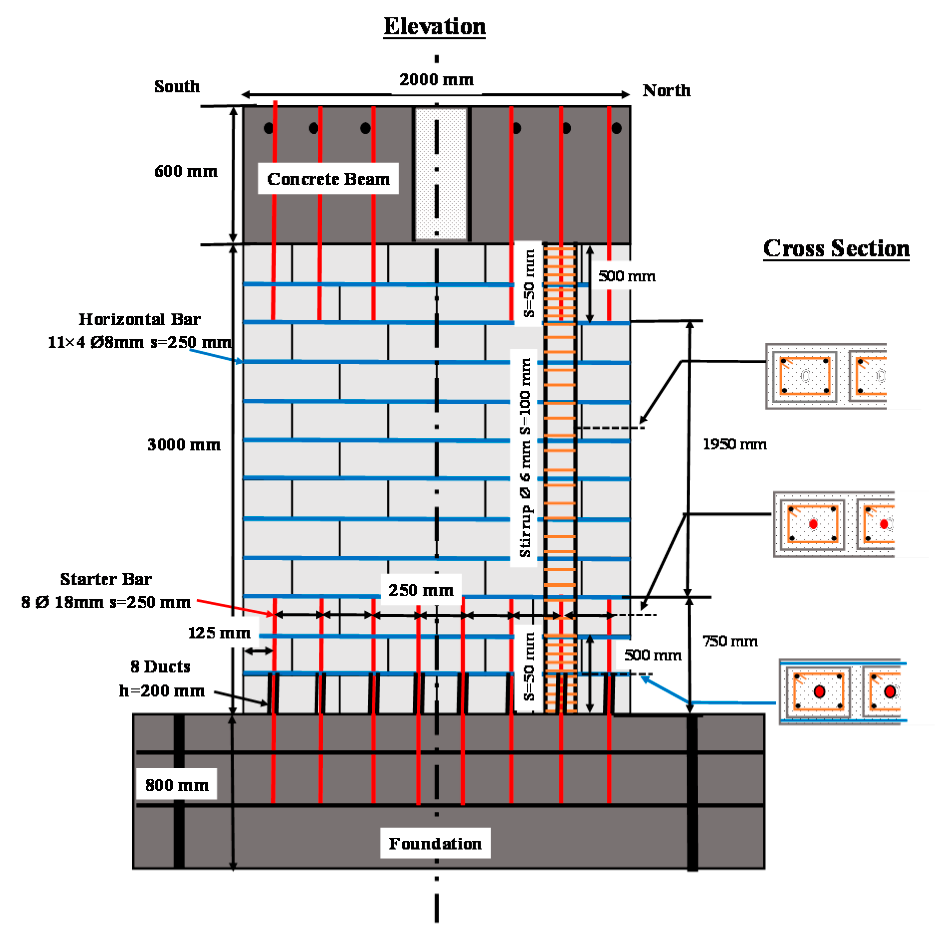
Few research studies have been reported on prefabricated reinforced masonry systems. Braun et al. [43] developed a prefabricated reinforced masonry system in Switzerland which was made of dry stacked hollow blocks with no mortar joints. The walling system was fully reinforced with a vertical reinforcement inserted into each hollow vertical core with grouting and horizontal bars placed in all bed joints. This study focused on investigating the suitable connection details between prefabricated wall and foundation through quasi-static cyclic in-plane shear tests in which two types of connection details between wall and foundation were considered. The dowel thickness and anchorage lengths were differed in both of these connections as shown in Figure 2. The in-plane cyclic shear testing of both walls revealed similar behaviour and thus are recommended for the wall to foundation connection. Conventionally, RM walls require starter bars at foundation/floor levels; thus, it can be said that using dowels to connect the prefabricated walls at foundation/floor level would not be an additional effort or cost.
Further, a team of researchers from Spain, Portugal and Italy have developed semi-prefabricated reinforced brick masonry light-weight vaults [44,45]. The construction of the vault consisted of two stages: (1) semi prefabricated steel-brick sheets were delivered at site and (2) construction was completed by filling and spraying the joints and top portion of the vaults. The structural performance of the semi-prefabricated vault was tested under instantaneous and sustain loading conditions to determine the load capacity, ductility and creep behaviour. Additionally, a predefined support displacement and instantaneous line loading were applied to verify the flexibility of the supporting members. The structural testing have revealed that the load capacity, ductility and joint integrity of the developed semi-prefabricated system were adequate.
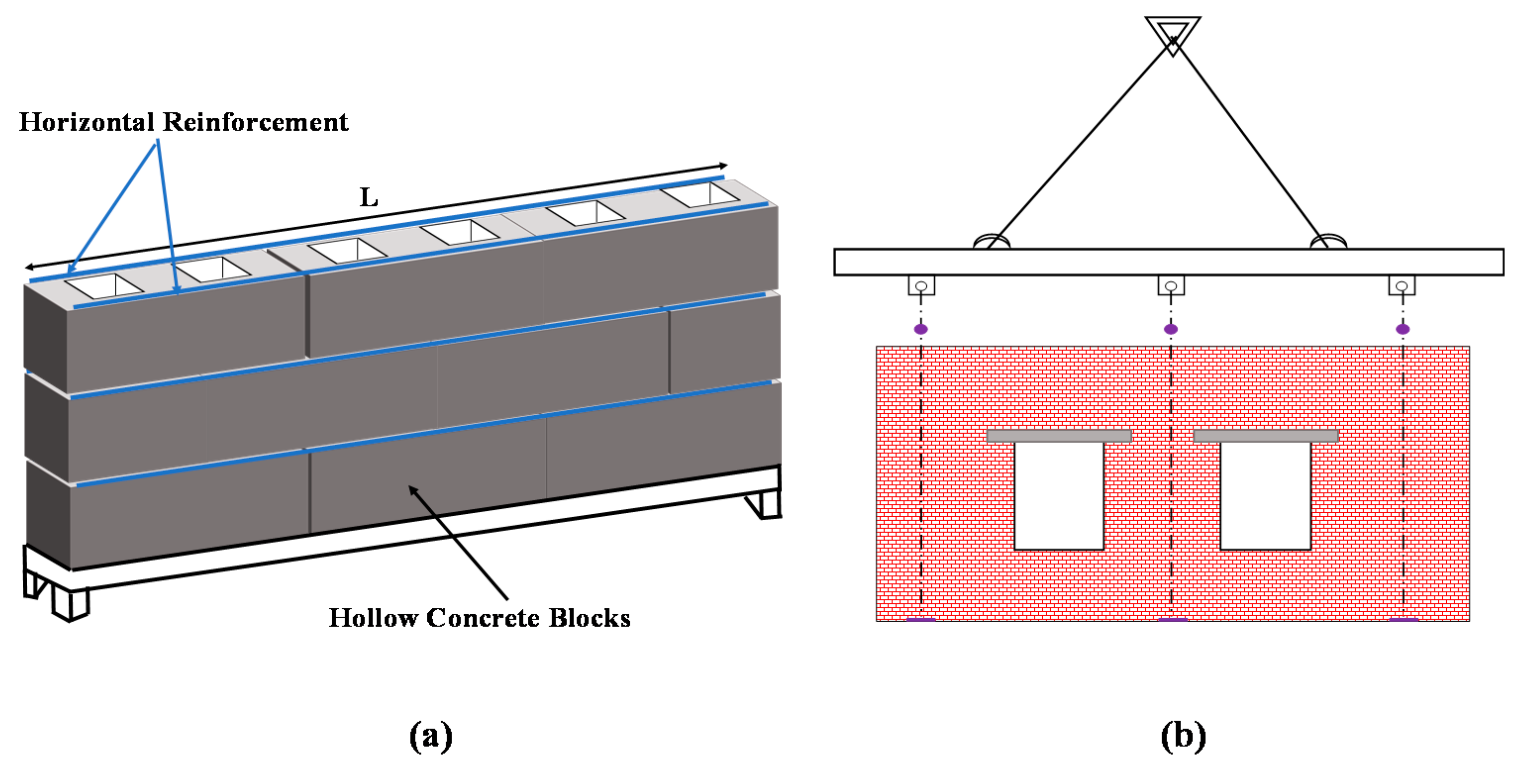
Recently, Muirhead et al. [46] patented a prefabricated reinforced masonry system in the USA. Hollow concrete blocks with slits on the face shells were used to fabricate the walls, where a provisional reinforcement is embedded in the slits, as shown in Figure 3a. The purpose of providing provisional reinforcement is to increase the tensile resistance of the walls during the erection. Therefore, 3 mm FRP bars were embedded in the slits with epoxy grout bonding. Further, U shaped blocks were laid on top and bottom of the wall with provisional reinforcement and grouted. Similar arrangements were proposed where the openings are required for lintels as shown in Figure 3b. Further anchor slings as indicated in Figure 3b were used to lift and place the walls during the transportation. Subsequently, the prefabricated reinforced masonry walls were transported to the site and the required vertical reinforcement was applied.
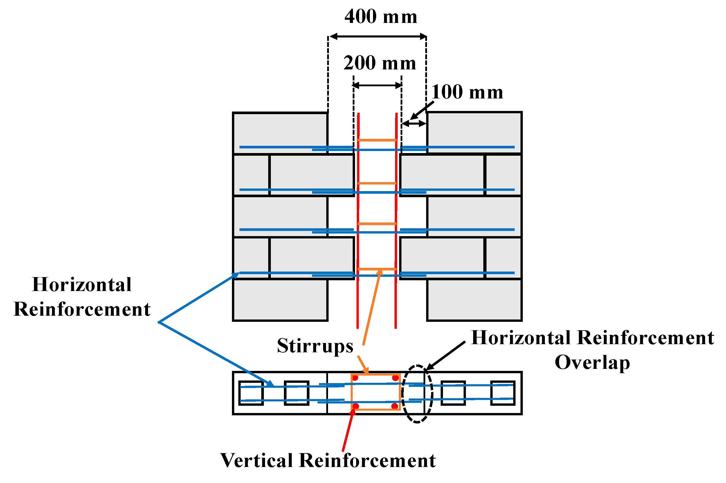
Zhang et al. [47] has reported a prefabricated reinforced masonry system for which they investigated the in-plane shear characteristics by varying horizontal reinforcement detail, axial compressive stress and vertical joint detailing. The detail of the proposed vertical joint arrangement is shown in Figure 4, where the vertical joints were designed at the web of the walls to avoid a complex reinforcement arrangement at the joints. The horizontal reinforcement bars were embedded into the joints to act as shear key in the vertical joints. The in-plane shear test results revealed that the failure modes of the vertically jointed wall were similar to that of conventional cast in-situ walls. Based on this research, it can be said that with the connection details available (wall to foundation and wall to wall), the RM can be an effective system to establish prefabricated masonry walls.
2.2. Post-Tensioned Masonry
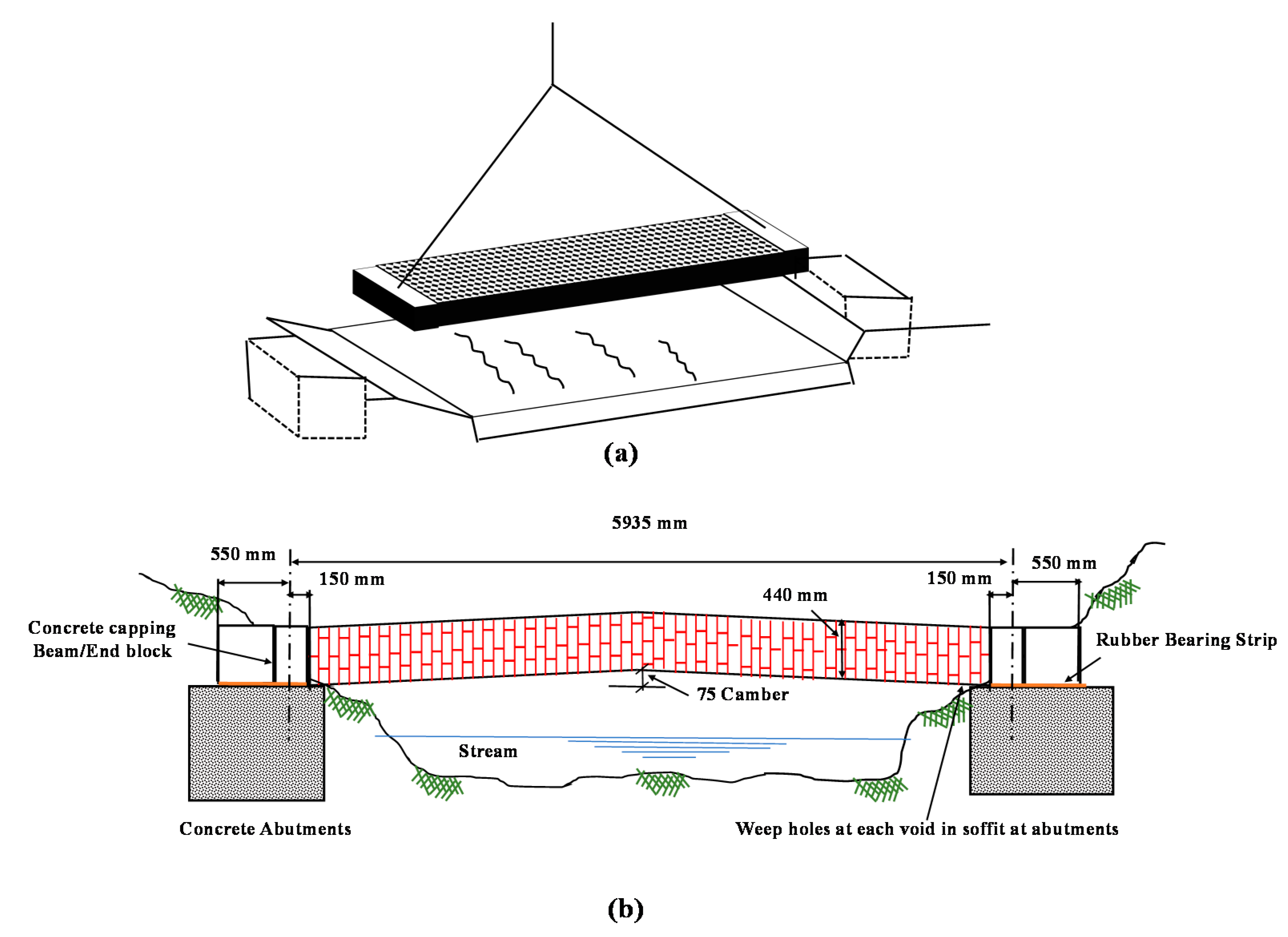
Similar to prefabricated RM walling system, pre-stressed/post-tensioned masonry systems are also a prospective solution for prefabrication of masonry. However, not much research efforts have been invested in assessing the performance of prefabricated prestressed masonries. Nevertheless, many studies were dedicated to investigating the in-plane and out of plane response of the cast in-situ prestressed masonry in the past [48,49,50,51,52]. Subsequently, rational design rules are available in the masonry design standards. Caine [53] outlined some of past projects that utilised prefabricated post-tensioned (PT) masonry elements in UK. It was highlighted that by using the PT method, horizontal masonry elements similar to bridge decks were prefabricated for pedestrian bridges. Figure 5 shows the schematic diagram of the prefabricated PT masonry deck used in Tring Bridge as outlined in Caine [47]. It was mentioned that the prefabricated panels were built vertical and then positioned horizontally as shown in Figure 5a. Adequate camber for the prestressed section was designed to match the required eccentricity of the pre-stressing force to resist the bending and shear actions. Figure 5b shows the cross-section view of the constructed foot bridge using the prefabricated masonry deck.
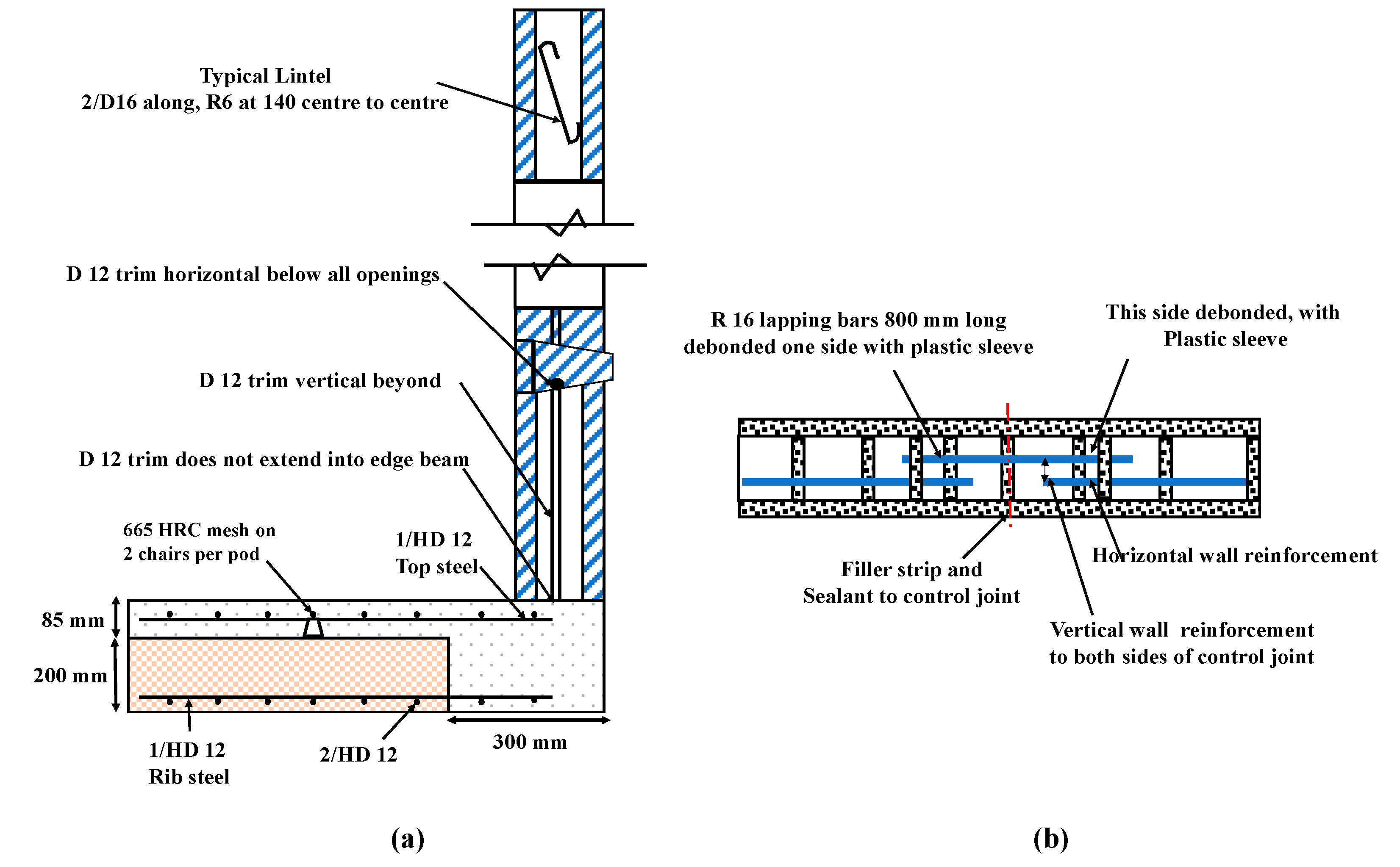
In absence of research details specific to prefabricated PT masonry, a similar analogy between RM and PT masonry can be drawn. Wight et al. [54] have outlined the application of PT masonry system for a single storey house in New Zealand. The walling system was designed to resist seismic action as per NZS 4203 [55]. Figure 6a,b provides typical wall to floor/foundation detailing of the PT wall and control joint detail between two wall panels. While detailing was specified for on-site construction, a similar technique could be developed to connect prefabricated PT masonry panels.
It must be highlighted that the PT walling system reported in Wight et al. [54] used dry-stack concrete blocks, where no mortar was used in erecting the walls. Subsequently, this technique would facilitate to construct the walls quicker than the conventional blockworks with the required bending and shear resistance provided by the PT. A similar dry-stack PT system was reported in Ota [56], where it was referred to as a Bolt-A-Blok wall system. The key feature of the system is the usage of bolts and treaded bars as the PT component in every layer of the blockwork. Moreover, there are plenty of studies on PT masonry walls with unbonded tendons [57,58,59,60], where unbonded tendons were mainly used to ease the requirement of grouting and as well as self-centring action during the lateral loading situation. Thus, it can be hypothesised that this technique can also be used in prefabrication of masonry walls, where the post-tensioning can be applied using the unbonded tendons off-site during the fabrication, which would facilitate transportation and erection, and the tendons can be later released once the walls are positioned and connected. This might provide a cost-effective prefabrication solution for masonry with more research studies on this aspect in the future.
2.3. Thin Layered Mortared Masonry
Thin layered mortared (TLM) masonry is another construction technique that could facilitate the erection of prefabricated masonry walls [61,62]. The main difference between the TLM and the conventional masonry is the composition and thickness of mortar used in the joints. Normally in TLM, the mortar thickness of 0.5 mm to 3 mm is adopted, which depends on the dimensional tolerance of units used. Typically, proprietary mortar mixes are used, where the constitutive materials (mainly sand) are much finer than those of conventional mortar mixes. Subsequently mortar application on unit layers in TLM masonry is carried out using mortar spreaders rather than traditional trowels, which make the TLM masonry construction relatively faster than the conventional construction with less wastage at site [63]. It was generally reported that the TLM construction is about 2–3 times faster than the conventional masonry construction [64]. Other than the European standards (EN 1996-1 [65]), other masonry design standards such as Australian standards AS 3700 [66], Canadian standards (CSA S304.1-04 [67]) and American standards (MSJC [68]) outline TLM mortar application with only Autoclaved aerated concrete (AAC) blocks.
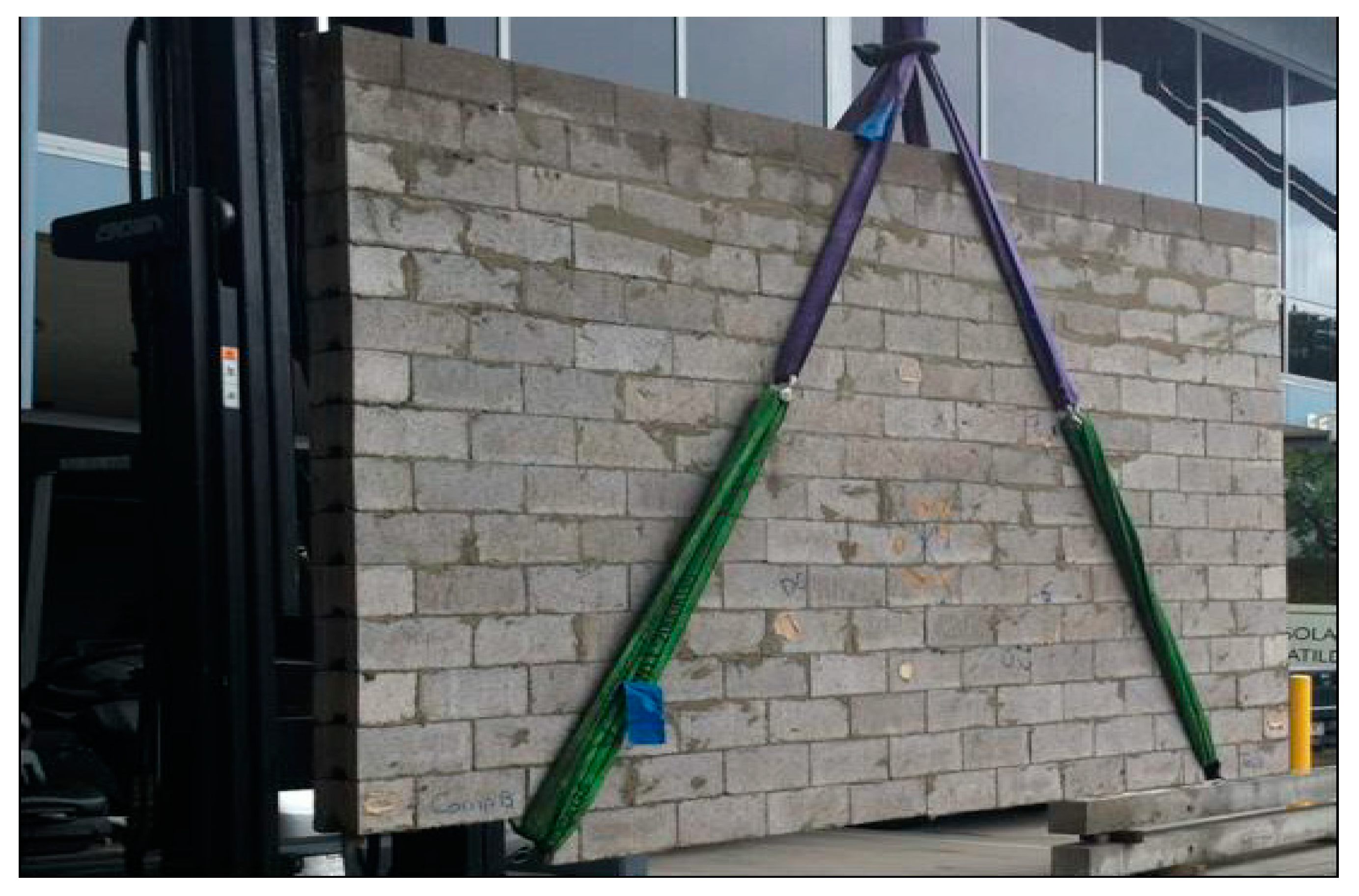
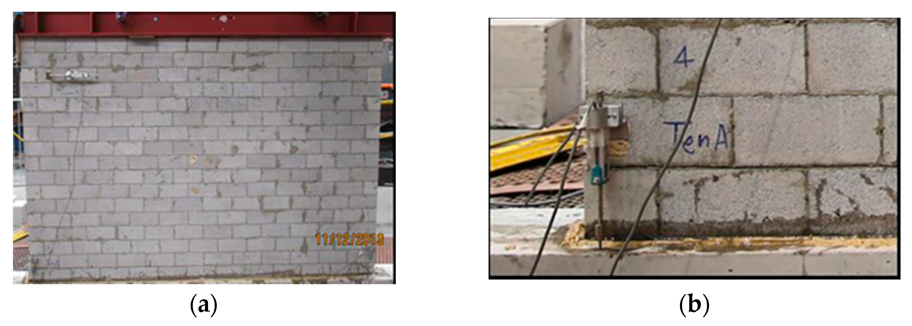
It was concluded in the previous studies that some of the proprietary mortars used in TLM masonry provided relatively higher bond strength than the conventional mortar [69,70], which could provide better resistance against the transportation and erection actions, if it is to be used as prefabricated systems. Additionally, if the bond strength of TLM masonry is not adequate to resist the erection forces, the system can be compensated with nominal reinforcement or prestressing. Comparatively fewer studies have been conducted on TLM masonry under various stress-states or investigating TLM masonry’s behaviour at a structural scale. Da Porto et al. [71] have reported that the TLM masonry shear walls made of perforated clay blocks portrayed moderately higher in-plane shear resistance and less deformity due to relatively higher bond strength characteristics between unit and mortar. Dhanasekar et al. [72] studied a high bond strength TLM masonry walling system to develop a prefabricated masonry walling system as shown in Figure 7. The developed system was demonstrated to withstand the handling actions as well as the in-plane shear and out of plane flexural actions. Further, Dhanasekar et al. [72] revealed that under low pre-compression (<0.5 MPa), which corresponded to less than 5% of the masonry compressive strength, the TLM concrete masonry shear walls would fail by base sliding due to the higher bond strength between unit and mortar, as shown in Figure 8, where the wall behaved similarly to reinforced concrete walls. Moreover, out-of-plane bending tests carried out by Kanyeto and Fried [73] revealed that the resistance is nearly four times higher than that of conventional masonry.
In addition, Ven der Meer et al. [74] have investigated creep and shrinkage characteristics of TLM masonry made of calcium silicate blocks to develop post-tensioned TLM masonry walls. It was reported that the final prestress loss due to creep and shrinkage were relatively less in the range of 16–24% due to reduced mortar thickness in TLM masonry. Later, the same researchers [75] evaluated the in-plane shear behaviour of post–tensioned TLM masonry made of calcium silicate blocks and highlighted that the system behaved quite similar to conventional masonry with improved shear resistance. Overall, it can be stated that the TLM masonry is a prospect to develop a prefabricated masonry walling system. Similar design concepts as those of conventional masonry can be adopted for TLM masonry, with relatively higher bonding strength characteristics according to the used mortar types.
3. Case Study of an Australian Prefabricated Masonry House
The review carried out in Section 2 highlights that the RM, PT and TLM construction methods are the prospects for developing prefabricated masonry walling systems. Therefore, for establishing the concept of a prefabricated masonry house design, these three walling systems along with the conventional masonry were taken into consideration for a case study of a typical house unit in Australia. The details of designing these walling systems for the considered house under various actions such as wind and earthquake as per the Australian standards were verified and outlined in this section. This case study details were then used to assess the life-cycle energy and a cost analysis later in the paper.
3.1. Prototype House
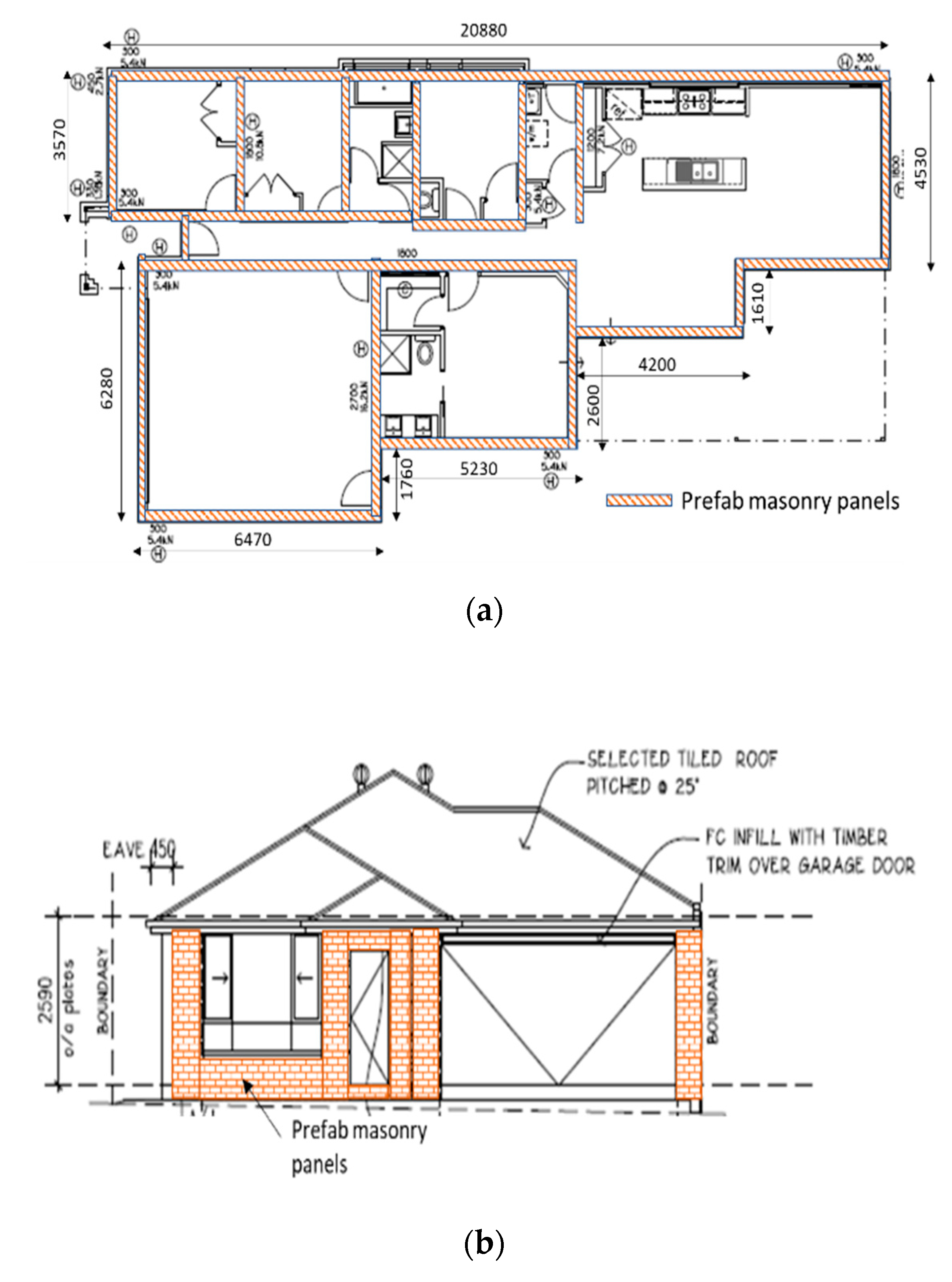
A typical house plan, as shown in Figure 9, was considered in this case study to explore the prospects of prefabricated masonry design, erection procedure on site, life-cycle energy and cost analyses. The typical housing plan was selected from a wider study of the existing housing types in Australia [76,77]. The house was designed for a regional area in Australia of medium seismicity (with a zone factor of 0.12 as per Australian Earthquake Standards, AS1170.4 [78]), where prefabricated masonry would solve the issue of shortage of labour and provide resistance against bushfire and cyclonic destructions. The considered house is a single-story dwelling, which is more common in housing, with a floor area of around 238 m2.
For prefabricated masonry walling systems, several possible scenarios as discussed in Section 2 were assessed, as summarised in Table 1. The conventional brick and TLM masonries were considered unreinforced (Type 1 and Type 2), and their thicknesses were assumed as 110 mm and 190 mm, respectively. Grouting was only considered for the RM wall system (Type 3), while the PT masonry system (Type 4) was designed for unbonded tendons without any grout. The detailed design of the house for the PMS as listed in Table 1 is described in the next sub-section.
3.2. Design Approaches
The selected house for this case study was designed to withstand gravity, earthquake and wind actions. A summary of design data used for the design scenarios is given in Table 2. The assumed parameters for soil type and terrain are also included in Table 2. Based on these assumed parameters, the design loads for gravity, earthquake and wind were calculated as shown under each category in the Table 2. The design standards that were followed to compute the different actions are also outlined.
The most critical walls subjected to compression due to gravity loads, in-plane shear due to earthquake and out-of-plane bending due to wind forces were identified. These individual walls were then designed, and their capacities were checked to resist these loads using Australian Masonry Standards (AS3700 [66]) provisions. The design of the critical walls was carried out for all the proposed conceptual PMS listed in Table 1. For safety against the tensile forces that can be caused due to lifting of prefabricated panels, TLM mortar of 3 mm thickness was used in all types of masonry walls design [82]. The design parameters and determined capacity of each type of masonry system is presented in Table 3 for comparison. The design parameters mentioned in Table 3, such as unit strength, dimensions, flexural and shear bond strengths, were typical values, used for a common masonry design practice in Australia.
As expected, all types of walling systems were found to be very safe in compression as the gravity loading in the selected single-story house was not very significant. The most critical wall under in-plane shear caused by the earthquake design loads shown in Table 2 also had sufficient capacity. However, for the out-of-plane wind pressure, both unreinforced systems (brick and block masonry) were found unsafe with less capacity as compared to the design wind pressure. AS 3700 [66] limits the flexural bond strength to be assumed for any masonry is 0.2 MPa; however, for TLM with high bond strength mortars, the bond strength can be up to 1.0 MPa [83]; thus, TLM can be used to resist higher out-of-plane bending if appropriate tensile and shear bond strength values are recommended in the standards. Nevertheless, comparison showed that for a safe design against each type of critical load, RM and PT systems will be more suitable to choose for the prefabricated masonry application.
3.3. Wall Erection Details
In this section, the possible concepts of prefabricated wall transportation and erections are discussed for the considered masonry walling systems in Section 3.1. Primarily, the prefabricated masonry wall sizes and shapes should be design based on the transport and lifting regulations as per the local requirements as well as considering the economy of the construction. Further, the prefabricated masonry wall support system relies on the type of wall to floor/foundation connection, lifting and transportation methods. Some of these concepts are drawn from the methods of transporting and erecting prefabricated concrete/reinforced concrete walls and are highlighted in the following sub-sections.
3.3.1. Design of Wall Lifting
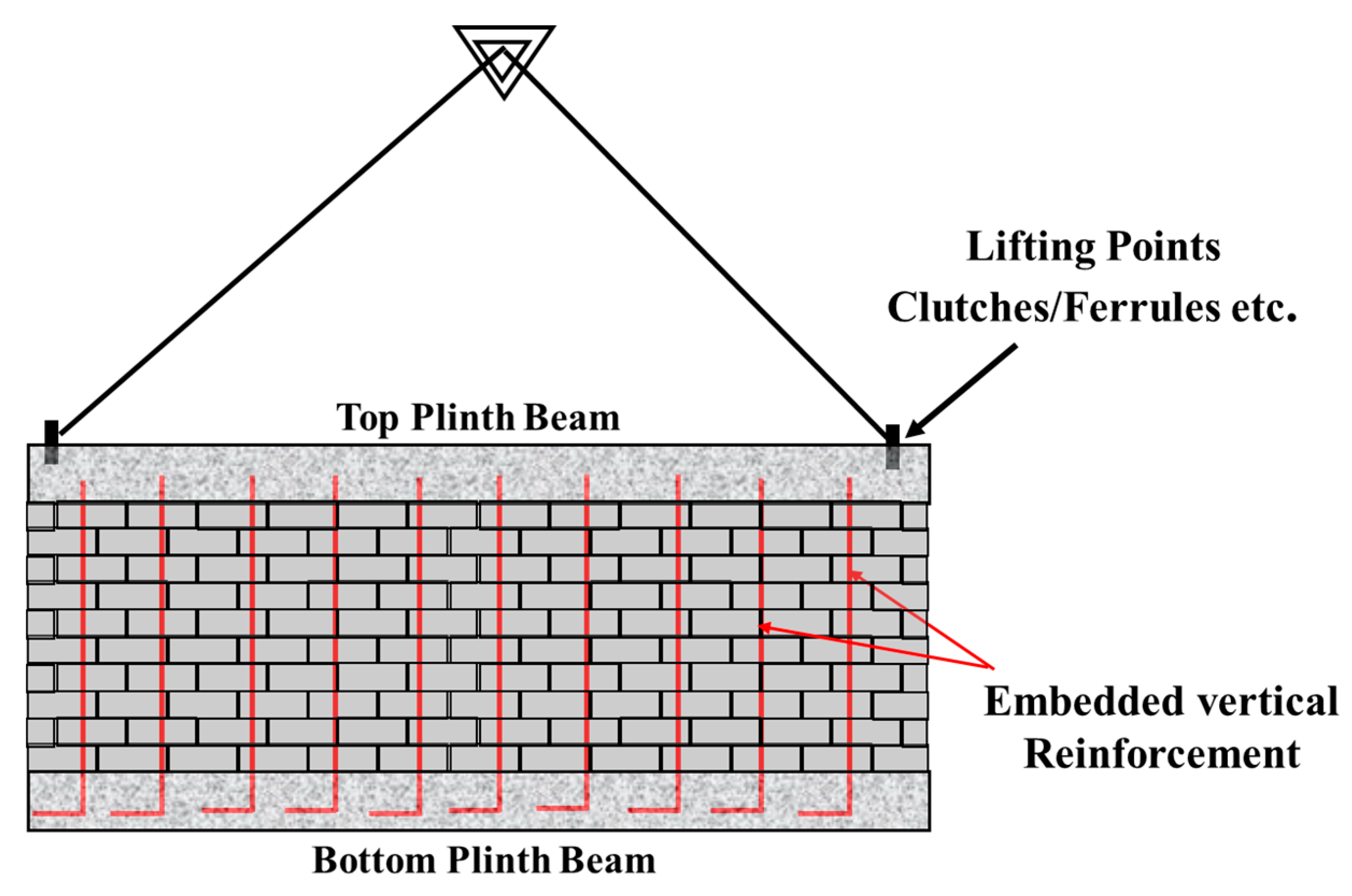
Specially made lifting hook clutches such as Reid Swift Lift or commercially available ferrules such as elephant foot ferrules combined with lifting eyes can be used to lift the prefabricated masonry wall. These lifting systems shall be embedded into the top plinth/lintel beam and can be designed as per AS3850 [84]. These lifting systems should be designed to an appropriate safety factor, which varies from 2.0 to 4.0 based on the type of component. The embedded element shall be verified according to the design of post-installed and cast-in fastenings in the wall according to AS5216 [85]. Further, the grout depth shall be increased locally where these lifting points are embedded if necessary. Depending on the span of the prefabricated masonry wall, the masonry shall rest on the bottom plinth and shall be suspended from the top plinth through the embedded reinforcement in the grout fills as shown in Figure 10, which implies that the RM and PT masonries (Type 3 and Type 4) can be effectively used to adopt these kinds of lifting arrangement. The spacing of the vertical reinforcement shall be determined based on the depth of the bottom plinth beam and the depth of the top plinth beam shall be designed based on the width of the panels. It must be mentioned that Type 1 and Type 2 masonry wall systems being unreinforced would be vulnerable to damage during transport and lifting, and therefore they are not preferable prefab masonry options. Otherwise, reinforcement bars/anchorages should be added to lifting positions to transfer the stresses.
3.3.2. Erection Methods of Walls
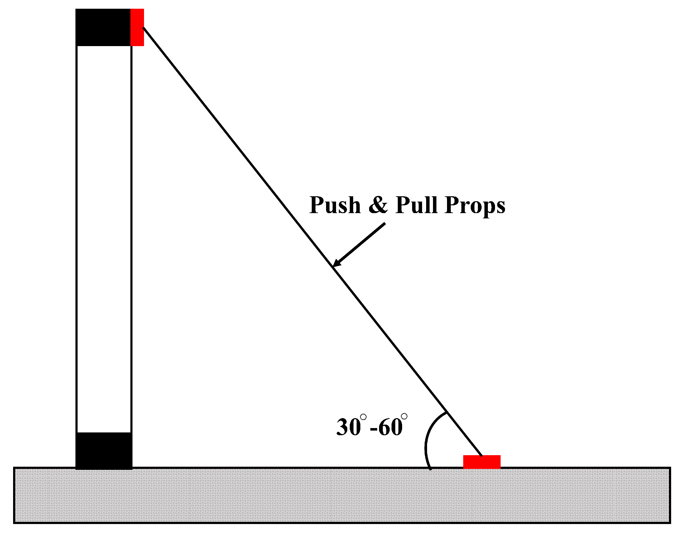
The prefabricated masonry wall system can be installed on the footing slab. Once the wall is lifted and placed on the location, it must be supported through temporary props, as illustrated in Figure 11. The temporary props are commonly called push and pull props which can be used to prop the masonry panels temporarily onto the ground floor slab. The props shall be connected to the top plinth beam and the inserts need to be designed based on AS 5216 [85]. The props shall be spaced based on the wind and intended lateral action during the erection of the walls.
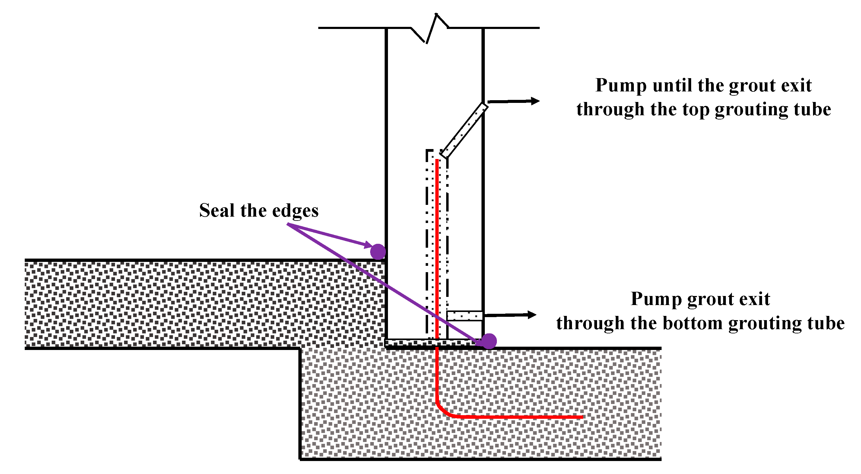
Moreover, Figure 12 shows the connection system between the prefabricated masonry wall and the flooring slab/foundation. Dowels shall be used between the ground floor and the bottom plinth beam to connect the modules to the ground floor. These dowels can be installed during the casting of the footing slab. The dowels shall be shorter and the same as the depth of the bottom plinth beam as there is minimal or no tension expected in dowels. The corrugated tubes on the bottom plinth shall be grouted using two grouting tubes (top and bottom) to ensure proper contact between the ground floor and the prefabricated masonry wall.
4. Life-Cycle Energy/Cost Analysis
In order to evaluate the sustainability of PMS with conventional construction, the life-cycle energy and cost analysis were carried out and reported in this section for the four types of masonry systems considered in Section 3. The energy consumptions and related greenhouse gas emissions (GHGE) were estimated for all four types of masonry wall systems. The energy consumptions and related GHGE for all the systems were assumed to be similar to the construction materials and the location of the house was the same for all systems. Thus, the energy and GHGE estimations were limited only to production and construction phases. The energy consumption and GHGE related to raw materials and transportation were accounted for in the production phase. Then, the energy consumption and GHGE from the construction or installation was considered in the construction phase. The equivalent coefficient for GHGE from Environmental Performance in Construction (EPiC) database [86] was used to derive the GHGE from the materials. The type of equipment and fuel to be used, and travel distance, were accounted for to derive the energy consumptions and related GHGE from transportation to installation.
Thereafter, the bottom-up and top-down approach based on the economic data and energy intensity were used to estimate the embodied energy (EE). An average national input–output data [87] with hybrid energy coefficients were used as per Equation (1) to calculate the EE. Table 4 shows the embodied energy intensities of materials used in both prefabricated and traditional masonry wall systems:
where Qm and EEm are the quantity of material and the embodied energy coefficient (GJ/unit), respectively.
Then, Equation (2) was used to determine the GHGE from the production and construction phases (GHGEP.C). Where GHGEE is the embodied GHGE of construction materials, GHGEP is the GHGE from the production of prefabricated wall systems, which includes consumption of electricity and fuel by equipment. GHGET and GHGES are GHGE from transportation of materials and on-site construction activities (including fuel and electricity consumption by the equipment), respectively. The GHGEE was obtained from Equation (3):
where GHGEE is the embodied GHGE coefficient (kg CO2-e/unit) of the construction materials, which was obtained from Table 4. Yan et al. [89] specified that the GHGE factor for diesel trucks used inland transport, which was used to estimate the GHGET using Equation (4). This study assumed that the construction site was located within an 80 km radius of the material sourced location. Then, the Equation (5) was used to calculate the energy consumption for transportation (ET):
where Di is the travel distance; fE is the fuel energy factor (0.002275 MJ/kg·km); and fGHGE is the GHGE factor for fuel (0.07 kg CO2-e/MJ) [89].
Further, in order to consider the workmanship in relation to the energy consumption, it was assumed that three skilled masons were employed to construct the wall systems and the average working hours were 6 h/day. The construction of the conventional brick house in the case study consumed 28 days, whilst the other three types of masonry houses consumed 40 days when traditional construction methods [90] are used. The number of days required were selected from the labour catalogue data in the Australian context and conservatively, 28 days for a brick masonry house and 40 days for RM, PT and TLM were fixed. As illustrated from the previous studies [91,92,93], the offsite construction time for the prefabricated element is less (i.e., about 20–30%). This offsite construction time can be further reduced by 20–40%, when using automation technologies. Thus, the construction duration was assumed to be reduced by 40% for manufacturing at a factory (i.e., prefabrication masonry systems), as the off-site construction reduces the construction complexity. Tam et al. [92] highlighted that the onsite installation time for precast structural wall is 15 min. Thus, the duration of on-site installation of a prefabricated masonry wall system was assumed to be 1.5 days. The office equipment (i.e., computers, printer, air conditioner, telephone and lighting) and other construction equipment (i.e., cement mixer and mobile crane) were assumed to be run on temporary power with a diesel engine. The energy content and GHGE factors for this engine were taken as 38.6 GJ/kL and 69.9 kg CO2-e/GJ [88]. The total energy consumption during the production and construction phases (EP.C) was calculated based on Equation (6):
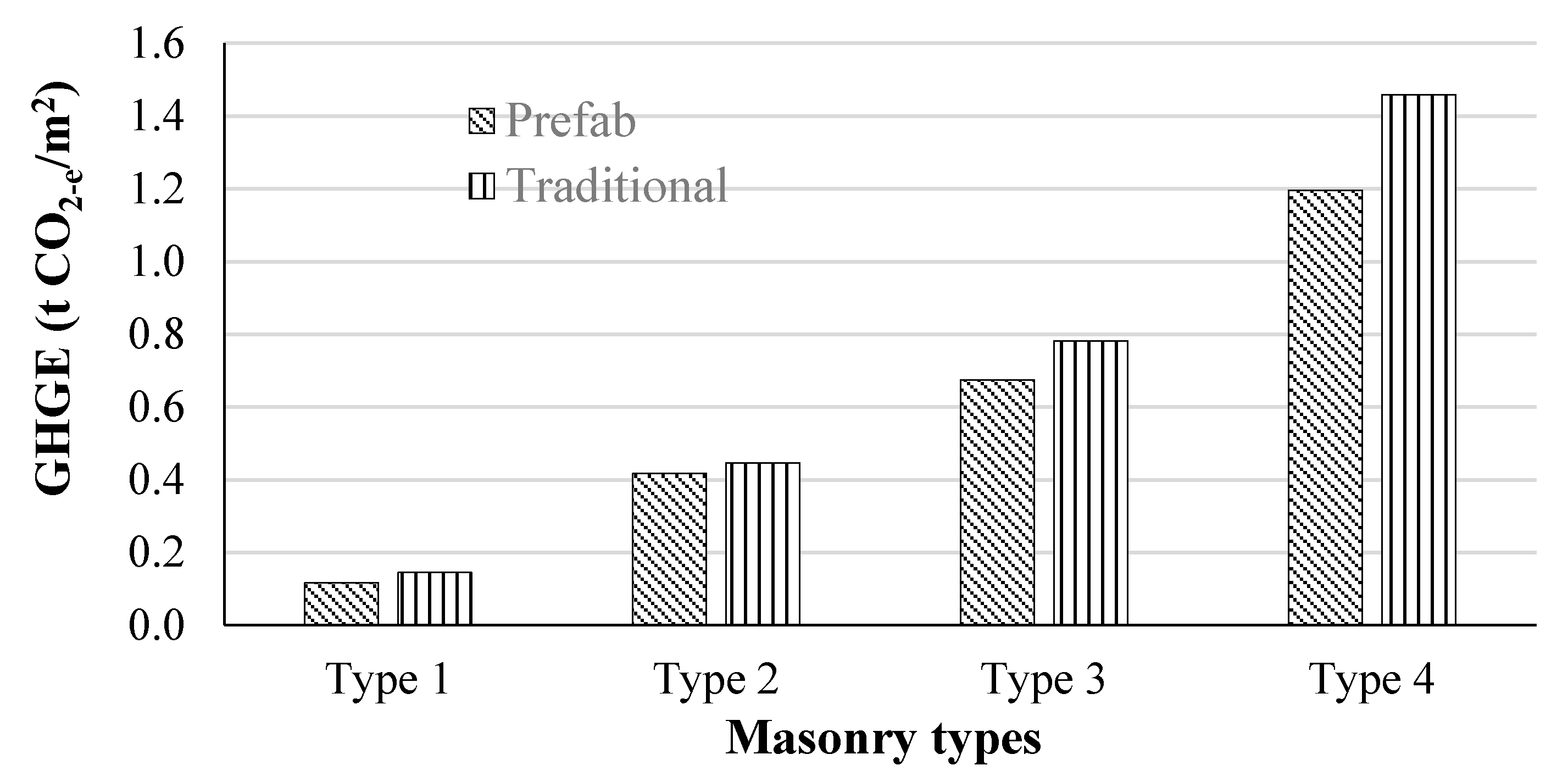
where ES and EP are the energy consumed on-site and off-site construction, respectively. Table 5 and Table 6 show the energy consumption and GHGE for the production and construction of the prefabricated and traditional (control) masonry wall construction, respectively. The energy consumption of traditional construction during the onsite construction phase is significantly higher than the prefabricated construction. This was due to the construction time, as the prefabricated construction was consumed only 1.5 days onsite, whilst the traditional construction consumed more than 20 days. During these periods, the construction activities require energy for equipment, cement mixture, lights, etc. Table 6 highlights that about 94% of GHGEP.C was contributed by raw materials in the prefabricated masonry wall system, whilst it was about 68% in the traditional masonry wall. Off-site and on-site construction of prefabricated wall system contributed about 16% of GHGEP.C. The construction of a traditional masonry wall accounted for about 30% of total GHGE. The GHGE from transportation for prefabricated and traditional masonry wall systems contributed about 3% and 2% of GHGEP.C, respectively. The total GHGEP.C related to the production and construction phases of prefabricated and traditional masonry wall systems is shown in Figure 13. The traditional masonry wall system showed 20% higher GHGE compared with the prefabricated masonry wall for the Type 1 system, and 7%, 14% and 18% in Type 2, Type 3 and Type 4, respectively. This was due to the high amount of energy intensive materials and their high embodied energy and GHGE coefficients as well as the higher construction time of the traditional masonry wall, compared to that of the prefabricated masonry.
5. Prospects, Challenges and Need for Research
It can be stated that the prefabricated masonry can be an alternative to the conventional labour-intensive masonry construction. From Section 2, it was established that the RM, PT and TLM masonries are the main options for masonry prefabrication, as these systems facilitate the transport and erection of the walls within the regulations allowed for prefabricated construction systems. Nevertheless, systematic research studies are needed to establish fully fledged PMS using these construction methods. It can be mentioned that the design guidelines for reinforced masonry, post-tensioned masonry and thin layered mortared masonry under various stress-states such as in-plane shear, out of plane bending and axial compression are already available in the standards. Therefore, system level research studies such as for the required connection configurations between the components (e.g., wall to floor/foundation and wall to wall), transportation and erection of PMS are needed. Primarily, the system level performance against static and dynamic (e.g., seismic) actions should also be evaluated for the PMS.
Furthermore, masonry is inherently a better material for fire and sound insulations. However, the performance of prefabricated masonry along with connection components should be assessed for fire and sound resistance. Additionally, sealing methods of connections and components of PMS is another area of concern against different environmental conditions, which needs systematic research studies to address the gap in the knowledge. Further, the choice of a prefabrication masonry system must be based on the economic aspects of the construction I to make it viable with regard to the life cycle cost of the system in addition to an adequate structural performance.
6. Summary and Conclusions
Researchers and practitioners have paid limited attention to understanding and designing PMS in the past. The reason for limited research in establishing the PMS differs across different countries due to cost effectiveness, limited awareness and lack of understanding of such systems’ performance. Therefore, in this study, potentiality of developing PMS in the Australian context has been assessed. Initially, the available studies with regard to masonry prefabricated systems and possible conventional masonry construction systems that can be used as prefabricated systems were appraised. Thereafter, to establish the concept of prefabricated design and construction, a prototype single storey house was selected as a case study to design three types of prefabricated masonry walling systems and their design and construction approaches were highlighted. Further to evaluate the sustainability of the prefabricated masonry construction systems, LCA analysis in terms of energy and carbon emissions were assessed and compared against conventional masonry construction system. Consequently, the following conclusions can be drawn on the prospect of prefabricated masonry construction in the Australian context.
- Reinforced, post-tensioned and thin layered mortared masonry systems are better options for establishing prefabricated masonry systems (PMS), as they have been shown to possess adequate structural capacities in different states of actions and their components facilitate providing better solutions for lifting and erection processes.
- The design concepts of prefabricated masonry can be drawn from masonry design standards for conventional masonry, while provisions for lifting and erections of the walling systems can be taken from well-established regulations available for prefabricated reinforced concrete walls. However, more systematic studies are needed to verify these provisions for prefabricated masonry walling systems.
- In terms of the sustainability perspective, the prefabricated masonry walling systems may perform better than the conventional masonry construction depending on the type of construction method adopted. Additionally, the LCA of the prefabricated masonry walls can be further enhanced by the selection of more sustainable materials and proper executions methods.
More systematic research studies are needed to establish fully-fledged PMS, especially structural performance at system level, where the behaviour of wall panels with its connection components against various actions should be assessed. Additionally, studies are needed for prefabricated masonry walls against realistic fire loadings and sound insulations.
Author Contributions
Conceptualization, J.T. and S.N.; Methodology, J.T. and S.N.; Formal analysis, T.Z. and S.N.; Investigation, J.T., T.Z. and S.N.; Data curation, M.A.; Writing—original draft preparation, J.T., T.Z. and S.N. Writing—review and editing, K.P.; Supervision, J.T. and K.P. All authors have read and agreed to the published version of the manuscript.
Funding
This research received no external funding.
Institutional Review Board Statement
Not applicable.
Informed Consent Statement
Not applicable.
Data Availability Statement
Necessary data are already given in the paper. However, any specific details used to support the findings of this study are available from the corresponding author upon request.
Acknowledgments
The authors acknowledge the technical support given to the project by the South Eastern University of Sri Lanka, Queensland University of Technology, Royal Melbourne Institute of Technology and Northumbria University.
Conflicts of Interest
Authors declare there is no conflict of interest in the study reported.
References
- Foraboschi, P. Masonry does not limit itself to only one structural material: Interlocked masonry versus cohesive masonry. J. Build. Eng. 2019, 26, 100831. [Google Scholar] [CrossRef]
- Thamboo, J.A.; Zahra, T.; Dhanasekar, R. Development of design methodology for mortarless masonry system: Case study—A resettlement housing colony. J. Build. Eng. 2020, 27, 100973. [Google Scholar] [CrossRef]
- Zahra, T.; Dhanasekar, M. Characterisation and strategies for mitigation of the contact surface unevenness in dry-stack masonry. Constr. Build. Mater. 2018, 169, 612–628. [Google Scholar] [CrossRef]
- Babatunde, S.A. Review of strengthening techniques for masonry using fiber reinforced polymers. Compos. Struct. 2017, 161, 246–255. [Google Scholar] [CrossRef]
- El-Dakhakhni, W.W.; Ahmed, A. Seismic response of reinforced-concrete masonry shear-wall components and systems: State of the art. J. Struct. Eng. 2017, 143, 03117001. [Google Scholar] [CrossRef]
- Hassanli, R.; ElGawady, A.; Mills, J.E. In-plane flexural strength of unbonded posttensioned concrete masonry walls. Eng. Struct. 2017, 136, 245–260. [Google Scholar] [CrossRef]
- Shrive, N.G.; Dhanasekar, M.; Masia, M.J.; Page, A.W. The response of concrete masonry with widely-spaced reinforcement to in-plane shear: State-of-the-art and research needs. Int. J. Mason. Res. Innov. 2018, 3, 369–381. [Google Scholar] [CrossRef]
- Minunno, R.; O’Grady, T.; Morrison, G.; Gruner, R.; Colling, M. Strategies for Applying the Circular Economy to Prefabricated Buildings. Buildings 2018, 8, 125. [Google Scholar] [CrossRef] [Green Version]
- Navaratnam, S.; Ngo, T.; Gunawardena, T.; Henderson, D. Performance Review of Prefabricated Building Systems and Future Research in Australia. Buildings 2019, 9, 38. [Google Scholar] [CrossRef] [Green Version]
- Gatheeshgar, P.; Poologanathan, K.; Gunalan, S.; Shyha, I.; Sherlock, P.; Rajanayagam, H.; Nagaratnam, B. Development of affordable steel-framed modular buildings for emergency situations (Covid-19). Structures 2021, 31, 862–875. [Google Scholar] [CrossRef]
- Gatheeshgar, P.; Poologanathan, K.; Gunalan, S.; Tsavdaridis, K.D.; Nagaratnam, B.; Iacovidou, E. Optimised cold-formed steel beams in modular building applications. J. Build. Eng. 2020, 32, 101607. [Google Scholar] [CrossRef]
- Li, M.; Li, G.; Huang, Y.; Deng, L. Research on investment risk management of Chinese prefabricated construction projects based on a system dynamics model. Buildings 2017, 7, 83. [Google Scholar]
- Kamali, M.; Hewage, K. Life cycle performance of modular buildings: A critical review. Renew. Sustain. Energy Rev. 2016, 62, 1171–1183. [Google Scholar] [CrossRef]
- Teng, Y.; Pan, W. Estimating and minimizing embodied carbon of prefabricated high-rise residential buildings considering parameter, scenario and model uncertainties. Build. Environ. 2020, 180, 106951. [Google Scholar] [CrossRef]
- Nadim, W.; Goulding, J.S. Off-site production: A model for building down barriers: A European construction industry perspective. Eng. Construct. Archit. Manag. 2011, 18, 82–101. [Google Scholar] [CrossRef]
- Blismas, N.; Wakefield, R. Drivers, constraints and the future of off-site manufacture in Australia. Construct. Innov. Inf. Process Manag. 2009, 9, 72–83. [Google Scholar] [CrossRef] [Green Version]
- Hampson, K.D.; Brandon, P. Construction 2020—A Vision for Australia’s Property and Construction Industry; CRC Construction Innovation: Brisbane, Australia, 2004. [Google Scholar]
- Lawson, R.M.; Ogden, R.G. Hybrid’s light steel panel and modular systems. Thin Wall Struct. 2008, 46, 720–730. [Google Scholar] [CrossRef]
- Lacey, A.W.; Chen, W.; Hao, H.; Bi, K. Structural response of modular buildings—An overview. J. Build. Eng. 2018, 16, 45–56. [Google Scholar] [CrossRef] [Green Version]
- Lacey, A.; Chen, W.; Hao, H.; Bi, K. Review of bolted inter-module connections in modular steel buildings. J. Build. Eng. 2019, 23, 207–219. [Google Scholar] [CrossRef]
- Ferdous, W.; Bai, Y.; Ngo, T.; Manalo, D.A.; Mendis, P. New advancements, challenges and opportunities of multi-storey modular buildings—A state-of-the-art review. Eng. Struct. 2019, 183, 883–893. [Google Scholar] [CrossRef]
- D’Orazio, M.; Stipa, P.; Sabbatini, S.; Maracchini, G. Experimental investigation on the durability of a novel lightweight prefabricated reinforced-EPS based construction system. Constr. Build. Mater. 2020, 252, 119134. [Google Scholar] [CrossRef]
- Loss, C.; Piazza, M.; Zandonini, R. Connections for steel–timber hybrid prefabricated buildings. Part I: Experimental tests. Constr. Build. Mater. 2016, 122, 781–795. [Google Scholar] [CrossRef]
- Navaratnam, S.; Small, D.W.; Gatheeshgar, P.; Poologanathan, K.; Thamboo, J.; Higgins, C.; Mendis, P. Development of cross laminated timber-cold-formed steel composite beam for floor system to sustainable modular building construction. Structures 2021, 32, 681–690. [Google Scholar] [CrossRef]
- Rinaldin, G.; Amadio, C.; Fragiacomo, M. A component approach for the hysteretic behaviour of connections in cross-laminated wooden structures. Earthq. Eng. Struct. Dyn. 2013, 42, 2023–2042. [Google Scholar] [CrossRef]
- Ronca, P.; Crespi, P.; Bonardi, D.; Palermo, A.; Pampanin, S. High performance wooden building subjected to seismic action. Int. J. Hous. Sci. Appl. 2014, 38, 161–172. [Google Scholar]
- Kurpinska, M.; Grzyl, B.; Kristowski, A. Cost Analysis of Prefabricated Elements of the Ordinary and Lightweight Concrete Walls in Residential Construction. Materials 2019, 12, 3629. [Google Scholar] [CrossRef] [PubMed] [Green Version]
- Zhang, X.; Zhang, A.-L.; Liu, X. Seismic performance of discontinuous cover-plate connection for prefabricated steel plate shear wall. J. Constr. Steel Res. 2019, 160, 374–386. [Google Scholar] [CrossRef]
- Longarini, N.; Crespi, P.; Scamardo, M. Numerical approaches for cross-laminated timber roof structure optimization in seismic retrofitting of a historical masonry church. Bull. Earthq. Eng. 2019, 18, 487–512. [Google Scholar] [CrossRef]
- Gatheeshgar, P.; Poologanathan, K.; Thamboo, J.; Roy, K.; Rossi, B.; Molkens, T.; Perera, D.; Navaratnam, S. On the fire behaviour of modular floors designed with optimised cold-formed steel joists. Structures 2021, 30, 1071–1085. [Google Scholar] [CrossRef]
- Biggs, D.T. Prefabricated Masonry Wall Panels. In Proceedings of the 7th International Masonry Conference, Dresden, Germany, 4–7 July 2006. [Google Scholar]
- Cavieres, A.; Gentry, R.; Al-Haddad, T. Knowledge-based parametric tools for concrete masonry walls: Conceptual design and preliminary structural analysis. Autom. Constr. 2011, 20, 716–728. [Google Scholar] [CrossRef]
- Da Porto, F.; Casarin, F.; Garbin, E.; Grendene, M.; Modena, C.; Valluzzi, M.R. Design Assisted by Testing of Semi-Prefabricated Reinforced Brick Masonry Vaults. In Proceedings of the 10th Canadian Masonry Symposium, Banff, AB, Canada, 8–12 June 20052005. [Google Scholar]
- Xu, W.; Yang, X.; Wang, F. Experimental Investigation on the Seismic Behavior of Newly-Developed Precast Reinforced Concrete Block Masonry Shear Walls. Appl. Sci. 2018, 8, 1071. [Google Scholar] [CrossRef] [Green Version]
- Wang, G.; Li, Y.; Zheng, N.; Ingham, J. Testing and modelling the in-plane seismic response of clay brick masonry walls with boundary columns made of precast concrete interlocking blocks. Eng. Struct. 2017, 131, 513–529. [Google Scholar] [CrossRef]
- Brameshuber, W.; Graubohm, M. Prefabricated masonry panel system with two-component polyurethane adhesive/Vorgefertigte Mauertafeln mit Zweikomponenten-Polyurethanklebstoff. Mauerwerk 2015, 19, 3–26. [Google Scholar] [CrossRef]
- Aye, L.; Ngo, T.; Crawford, R.; Gammampila, R.; Mendis, P. Life cycle greenhouse gas emissions and energy analysis of prefabricated reusable building modules. Energy Build. 2012, 47, 159–168. [Google Scholar] [CrossRef]
- Teng, Y.; Li, K.; Pan, W.; Ng, T. Reducing building life cycle carbon emissions through prefabrication: Evidence from and gaps in empirical studies. Build. Environ. 2018, 132, 125–136. [Google Scholar] [CrossRef]
- Zhu, H.; Hong, J.; Shen, G.Q.; Mao, C.; Zhang, H.; Li, Z. The exploration of the life-cycle energy saving potential for using prefabrication in residential buildings in China. Energy Build. 2018, 166, 561–570. [Google Scholar] [CrossRef]
- Samani, P.; Gregory, J.; Leal, V.; Mendes, A.; Correia, N. Lifecycle Cost Analysis of Prefabricated Composite and Masonry Buildings: Comparative Study. J. Arch. Eng. 2018, 24, 05017012. [Google Scholar] [CrossRef]
- Roberts, J.J.; Hogg, J.; Fried, A.F. Prefabricated Brickwork A Review of Recent Applications. In Proceedings of the Ninth Canadian Symposium, Toronto, ON, Canada, 20–22 April 2001. [Google Scholar]
- Brocato, M.; Deleporte, W.; Mondardini, L.; Tanguy, J.-E. A Proposal for a New Type of Prefabricated Stone Wall. Int. J. Space Struct. 2014, 29, 97–112. [Google Scholar] [CrossRef]
- Braun, B.; Rupf, M.; Beyer, K.; Dazio, A. Quasi-static cyclic tests of two prefabricated, reinforced masonry walls. In Proceedings of the 14th European Conference on Earthquake Engineering, Ohrid, Macedonia, 30 August–3 September 2010. [Google Scholar]
- Lopez-Almansa, F.; Roca, P.; Sarrablo, V.; Cahís, X.; Canet, J.M. Experiments on Reinforced Brick Masonry Vaulted Light Roofs. ACI Struct. J. 2010, 107, 355–363. [Google Scholar] [CrossRef]
- López-Almansa, F.; Sarrablo, V.; Lourenco, P.B.; Barros, J.A.O.; Roca, P.; da Porto, F.; Modena, C. Reinforced brick masonry light vaults: Semi-prefabrication, construction, testing and numerical modelling. Constr. Build. Mater. 2010, 24, 1799–1814. [Google Scholar] [CrossRef] [Green Version]
- Muirhead, D.; Gendron, J.; Biggs, D.; Winter, S. Prefabricated Masonry Walls. U.S. Patent 10,554, 583 B2, 28 June 2020. [Google Scholar]
- Zhang, Z.; Wang, F.; Chi, B. Seismic performance of shear-critical prefabricated reinforced masonry shear walls with innovative vertical joint connections. Eng. Struct. 2020, 219, 110958. [Google Scholar] [CrossRef]
- Ryu, D.; Wijeyewickrema, A.C.; ElGawady, M.; Madurapperuma, M.A.K.M. Effects of tendon spacing on in-plane behavior of posttensioned masonry walls. J. Struct. Eng. 2014, 140, 04013096. [Google Scholar] [CrossRef]
- Ismail, N.; Ingham, J.M. Cyclic Out-of-Plane Behavior of Slender Clay Brick Masonry Walls Seismically Strengthened Using Posttensioning. J. Struct. Eng. 2012, 138, 1255–1266. [Google Scholar] [CrossRef]
- Hassanli, R.; ElGawady, M.A.; Mills, J.E. Strength and Seismic Performance Factors of Posttensioned Masonry Walls. J. Struct. Eng. 2015, 141, 04015038. [Google Scholar] [CrossRef]
- Popehn, J.R.B.; Schultz, A.E. Influence of imperfections on the out-of-plane flexural strength of post-tensioned masonry walls. Constr. Build. Mater. 2013, 41, 942–949. [Google Scholar] [CrossRef]
- Kalliontzis, D.; Schultz, A. Improved estimation of the reverse-cyclic behavior of fully-grouted masonry shear walls with unbonded post-tensioning. Eng. Struct. 2017, 145, 83–96. [Google Scholar] [CrossRef]
- Caine, J. Developments in In Situ and prefabricated masonry for the 21st century. Prog. Struct. Eng. Mater. 1998, 1, 263–270. [Google Scholar] [CrossRef]
- Wight, G.D.; Ingham, J.M.; Wilton, A.R. Innovative seismic design of a posttensioned concrete masonry house. Can. J. Civil Eng. 2007, 34, 1393–1402. [Google Scholar] [CrossRef]
- NZS 4203:1992. General Structural Design and Design Loadings for Buildings; WorkSafe: Wellington, New Zealand, 1992. [Google Scholar]
- Ota, H. Experimental Study of Mortarless Post-Tensioned Masonry Walls and Development of Design Guidelines. Master’s Thesis, The Pennsylvania State University, State College, PA, USA, 2011. [Google Scholar]
- Wight, G.D.; Ingham, J.M. Tendon Stress in Unbonded Posttensioned Masonry Walls at Nominal In-Plane Strength. J. Struct. Eng. 2008, 134, 938–946. [Google Scholar] [CrossRef]
- Bean, J.; Schultz, A. Flexural capacity of post-tensioned masonry walls: Code review and recommended procedure. PTI J. 2003, 1, 28–44. [Google Scholar]
- Hassanli, R.; ElGawady, M.A.; Mills, J.E. Simplified approach to predict the flexural strength of self-centering masonry walls. Eng. Struct. 2017, 142, 255–271. [Google Scholar] [CrossRef]
- Kalliontzis, D.; Schultz, A.E. Characterizing the in-plane rocking response of masonry walls with unbonded posttensioning. J. Struct. Eng. 2017, 143, 04017110. [Google Scholar] [CrossRef]
- Dhanasekar, M.; Da Porto, F. Review of the progress in thin bed technology for masonry construction. In Proceedings of the 11th Canadian Masonry Symposium, Toronto, ON, Canada, 31 May–3 June 2009. [Google Scholar]
- Thamboo, J.A.; Dhanasekar, M. Behaviour of thin layer mortared concrete masonry under combined shear and compression. Aust. J. Struct. Eng. 2016, 17, 39–52. [Google Scholar] [CrossRef] [Green Version]
- Dhanasekar, M.; Thamboo, J.A.; Nazir, S.; Nardone, A.; McGoldrick, T. State-of-the-art of the Australian Thin Bed Concrete Structural Masonry, Concrete 2013. In Proceedings of the 26th Biennial National Conference of the Concrete Institute of Australia, Gold Coast, QLD, Australia, 16–18 October 2013. [Google Scholar]
- Thamboo, J. Material characterisation of thin layer mortared clay masonry. Constr. Build. Mater. 2020, 230, 116932. [Google Scholar] [CrossRef]
- British Standards Institution. BS EN 1996-1-1: Eurocode 6: Design of Masonry Structures—Part 1–1: General Rules for Reinforced and Unreinforced Masonry Structures; British Standards Institution: London, UK, 2005. [Google Scholar]
- Standards Australia. AS 3700, Design of Masonry Structures; Standards Australian: Sydney, NSW, Australia, 2018. [Google Scholar]
- CSA. Design of Masonry Structures; CSA S304.1-04 (R2010); Canadian Standards Association: Mississauga, ON, Canada, 2010. [Google Scholar]
- Masonry Standards Joint Committee (MSJC). Building Code Requirements for Masonry Structures; TMS 402/ASCE 5/ACI 530; MSJC: New York, NY, USA, 2011. [Google Scholar]
- Thamboo, J.A.; Dhanasekar, M.; Yan, C. Flexural and shear bond characteristics of thin layer polymer cement mortared concrete masonry. Constr. Build. Mater. 2013, 46, 104–113. [Google Scholar] [CrossRef] [Green Version]
- Thamboo, J.A.; Dhanasekar, M. Characterisation of thin layer polymer cement mortared concrete masonry bond. Constr. Build. Mater. 2015, 82, 71–80. [Google Scholar] [CrossRef] [Green Version]
- Da Porto, F.; Guidi, G.; Garbin, E.; Modena, C. In-Plane Behavior of Clay Masonry Walls: Experimental Testing and Finite-Element Modeling. J. Struct. Eng. 2010, 136, 1379–1392. [Google Scholar] [CrossRef]
- Dhanasekar, M.; Thamboo, J.A.; Nazir, S. On the in-plane shear response of the high bond strength concrete masonry walls. Mater. Struct. 2017, 50, 214. [Google Scholar] [CrossRef]
- Kanyeto, O.; Fried, A. Flexural behaviour of thin joint concrete blockwork: Experimental results. Constr. Build. Mater. 2011, 25, 3639–3647. [Google Scholar] [CrossRef]
- Van der Meer, L.J.; Martens, D.R.W.; Vermeltfoort, A.T. Prestress loss due to creep and shrinkage of high-strength calcium silicate element masonry with thin-layer mortar. Mater. Struct. 2013, 46, 2091–2108. [Google Scholar] [CrossRef]
- Van Der Meer, L.; Martens, D.; Vermeltfoort, A. UPT rectangular and flanged shear walls of high-strength CASIEL-TLM masonry: Experimental and numerical push-over analysis. Eng. Struct. 2013, 49, 628–642. [Google Scholar] [CrossRef]
- Navaratnam, S. Wind Load Sharing and Vertical Load Transfer from Roof to Wall in A Timber-Framed House. Ph.D. Thesis, James Cook University, Douglas, QLD, Australia, 2016. [Google Scholar]
- Satheeskumar, N.; Henderson, D.; Ginger, J.; Wang, C.-H. Finite element modelling of the structural response of roof to wall framing connections in timber-framed houses. Eng. Struct. 2017, 134, 25–36. [Google Scholar] [CrossRef]
- Standards Australia. AS1170.4, Structural Design Actions Part 4: Earthquake Actions in Australia; Standards Australia: Sydney, NSW, Australia, 2007. [Google Scholar]
- Standards Australia. AS/NZS 1170.1, Structural Design Actions Part 1: Permanent, Imposed and Other Actions; Standards Australia: Sydney, NSW, Australia, 2002. [Google Scholar]
- Standards Australia. AS/NZS 1170.0, Structural Design Actions Part 0: General Principles; Standards Australia: Sydney, NSW, Australia, 2002. [Google Scholar]
- Standards Australia. AS/NZS 1170.2, Structural Design Wind Actions Part 0: General Principles; Standards Australia: Sydney, NSW, Australia, 2011. [Google Scholar]
- Thamboo, J.A.; Dhanasekar, M. Effect of concrete block height variation to the shear bond strength of thin layer mortared masonry. Int. J. Mason. Res. Innovat. 2018, 3, 174–193. [Google Scholar] [CrossRef]
- Thamboo, J.A. Development of Thin Layer Mortared Concrete Masonry. Ph.D. Thesis, Queensland University of Technology, Brisbane City, QLD, Australia, 2014. [Google Scholar]
- Standards Australia. AS 3850.1:2015, Prefabricated Concrete Elements General Requirements; Standards Australia: Sydney, NSW, Australia, 2015. [Google Scholar]
- Standards Australia. AS 5216:2018, Design of Post-Installed and Cast in Fastenings in Concrete; Standards Australia: Sydney, NSW, Australia, 2018. [Google Scholar]
- Robert, C.; André, S.; Fabian, P. Environmental Performance in Construction (EPIC) Database; The University of Melbourne: Parkville, VIC, Australia, 2019. [Google Scholar]
- Department of the Environment and Energy. National Greenhouse Accounts Factors; Department of the Environment and Energy: Canberra, ACT, Australia, 2019. [Google Scholar]
- Crawford, R. Life Cycle Assessment in the Built Environment; Routledge: London, UK, 2011. [Google Scholar]
- Yan, H.; Shen, Q.; Fan, L.C.; Wang, Y.; Zhang, L. Greenhouse gas emissions in building construction: A case study of One Peking in Hong Kong. Build. Environ. 2010, 45, 949–955. [Google Scholar] [CrossRef] [Green Version]
- Australian Bureau of Statistics. Building Activity Australia—Average Dwelling Completion Times; Australian Bureau of Statistics: Belconnen, ACT, Australia, 2020. [Google Scholar]
- Jayalath, A.; Navaratnam, S.; Ngo, T.; Mendis, P.; Hewson, N.; Aye, L. Life cycle performance of Cross Laminated Timber mid-rise residential buildings in Australia. Energy Build. 2020, 223, 110091. [Google Scholar] [CrossRef]
- Tam, V.W.; Fung, I.W.; Sing, C.P.; Ogunlana, S.O. Best practice of prefabrication implementation in the Hong Kong public and private sectors. J. Clean. Prod. 2015, 109, 216–231. [Google Scholar] [CrossRef]
- Lawson, R.M.; Ogden, R.G.; Bergin, R. Application of Modular Construction in High-Rise Buildings. J. Arch. Eng. 2012, 18, 148–154. [Google Scholar] [CrossRef]
Figure 1.
Lifting of a prefabricated façade masonry walling system.

Figure 2.
Prefabricated reinforced masonry: wall to foundation connection, Braun et al. [43].
Figure 2.
Prefabricated reinforced masonry: wall to foundation connection, Braun et al. [43].

Figure 3.
Prefabricated RM system developed by Muirhead et al. [46] (a) Sectional view of the prefabricated wall and (b) lifting position of the walls.
Figure 3.
Prefabricated RM system developed by Muirhead et al. [46] (a) Sectional view of the prefabricated wall and (b) lifting position of the walls.

Figure 4.
Proposed vertical joints for prefabricated RM walls by Zhang et al. [47].
Figure 4.
Proposed vertical joints for prefabricated RM walls by Zhang et al. [47].

Figure 5.
Prefabricated PT masonry bridge decks used (Caine): [53] (a) positioning of prefabricated masonry deck and (b) cross sectional view of the deck.
Figure 5.
Prefabricated PT masonry bridge decks used (Caine): [53] (a) positioning of prefabricated masonry deck and (b) cross sectional view of the deck.

Figure 6.
Connection detailing of PT masonry wall [54]: (a) wall to floor/foundation and (b) wall to wall with control joint.
Figure 6.
Connection detailing of PT masonry wall [54]: (a) wall to floor/foundation and (b) wall to wall with control joint.

Figure 7.
Lifting of TLM masonry walls made of concrete blocks [72].
Figure 7.
Lifting of TLM masonry walls made of concrete blocks [72].

Figure 8.
In-plane shear wall testing of TLM masonry walls [72]: (a) in-plane shear testing arrangement and (b) sliding failure of a TLM wall.
Figure 8.
In-plane shear wall testing of TLM masonry walls [72]: (a) in-plane shear testing arrangement and (b) sliding failure of a TLM wall.

Figure 9.
House layout selected for the design and LCE analyses: (a) Plan view and (b) Elevation view.
Figure 9.
House layout selected for the design and LCE analyses: (a) Plan view and (b) Elevation view.

Figure 10.
Lifting method of masonry walls.

Figure 11.
Propping method of masonry walls.

Figure 12.
Connection of masonry walls with the base.

Figure 13.
Comparison of GHGE for prefabricated and conventional masonry construction.


Table 1.
Considered masonry walling systems.
| Notation | Prefab Walling System | Wall Thickness | Reinforcement | Grouting |
|---|---|---|---|---|
| Type 1 | Conventional clay brick masonry | 110 mm | × | × |
| Type 2 | TLM Hollow block masonry | 190 mm | × | × |
| Type 3 | PT block masonry | 190 mm | √ | × |
| Type 4 | RM block masonry | 190 mm | √ | √ |
Table 2.
Loading scenarios and magnitudes.
| Load Scenario | Magnitude | Relevant Code |
|---|---|---|
| Gravity Loads | ||
| Roof tiles and roof truss load | 1.3 kPa | AS1170.1 [79] |
| Imposed load | 0.5 kPa | AS1170.1 [79] |
| Masonry wall load | 2.1 kPa | AS1170.1 [79] |
| Earthquake Loads | ||
| Importance level | 2 | AS1170.0 [80] |
| Soil class (soft rock) | Be | AS1170.4 [78] |
| Zone factor (Z) | 0.12 | AS1170.4 [78] |
| Earthquake design category | I | AS1170.4 [78] |
| Base shear (V) | 90 kN | AS1170.4 [78] |
| Wind Loads | ||
| Wind region | A3 | AS1170.2 [81] |
| Regional wind speed | 45 m/s | AS1170.2 [81] |
| Terrain category | 3 | AS1170.2 [81] |
| Wind pressure on walls | 0.8 kPa | AS1170.2 [81] |
Table 3.
Design details of critical walls for different masonry systems.
| Design Parameter | Type 1 | Type 2 | Type 3 | Type 4 |
|---|---|---|---|---|
| Unit strength | 15 MPa | 15 MPa | 15 MPa | 15 MPa |
| Unit height | 76 mm | 190 mm | 190 mm | 190 mm |
| Face-shell thickness | n/a | 30 mm | 30 mm | 30 mm |
| Mortar type | M3 | M3 | M3 | M3 |
| Mortar thickness | 3 mm | 3 mm | 3 mm | 3 mm |
| compressive strength | 7 MPa | 8 MPa | 8 MPa | 8 MPa |
| 0.2 MPa | 0.2 MPa | 0.2 MPa | 0.2 MPa | |
| 0.25 MPa | 0.25 MPa | 0.25 MPa | 0.25 MPa | |
| n/a | n/a | n/a | 25 MPa | |
| Vertical bars | n/a | n/a | 12.7 mm strand | 1 N16 |
| Horizontal bars | n/a | n/a | n/a | 1 N12 |
| Compression Design (Maximum Load = 13.5 kN/m) | ||||
| Compression capacity | 190 kN/m (safe) | 140 kN/m (safe) | 232 kN/m (safe) | 242 kN/m (safe) |
| In-plane Shear Design (Maximum Load = 7 kN/m) | ||||
| In-plane shear capacity | 17 kN/m (safe) | 9 kN/m (safe) | 9 kN/m (safe) | 70 kN/m (safe) |
| Out-of-plane bending Design (Maximum Load = 0.8 kPa) | ||||
| Out-of-plane bending capacity | 0.1 kPa (unsafe) | 0.5 kPa(unsafe) | 6.2 kPa (safe) | 5.7 kPa (safe) |
Table 4.
The EE intensity, embodied greenhouse gas (GHGEE) intensity and density of construction material used in the wall systems [88].
Table 4.
The EE intensity, embodied greenhouse gas (GHGEE) intensity and density of construction material used in the wall systems [88].
| Material | Density (kg/m3) | Unit | EE Coefficient (MJ/Unit) | |
|---|---|---|---|---|
| Grout (25 MPa) | 2400 | m3 | 2581 | 361 |
| Steel | 7850 | kg | 38.8 | 2.9 |
| Mortar | 1858 | kg | 3.9 | 0.1 |
| Gypsum Plasterboard | 885 | kg | 6.5 | 0.4 |
| Brick | 1920 | kg | 3.5 | 0.32 |
| Rockwool | 70 | kg | 57.1 | 3.8 |
| Block | 1400 | kg | 35.2 | 3.2 |
Table 5.
Energy consumption (GJ) production to and construction phases.
| Details | Type 1 | Type 2 | Type 3 | Type 4 | ||||
|---|---|---|---|---|---|---|---|---|
| Prefab | Conv | Prefab | Conv | Prefab | Conv | Prefab | Conv | |
| Embodied Raw materials (EE) | 373 | 455 | 1328 | 1697 | 1337 | 1708 | 1442 | 1844 |
| Offsite construction (EP) | 70 | - | 75 | - | 75 | - | 75 | - |
| Onsite Transport (ET) | 12 | 12 | 7 | 7 | 8 | 8 | 23 | 23 |
| Onsite construction (ES) | 7 | 174 | 7 | 187 | 7 | 187 | 7 | 187 |
| Total (EP.C) | 462 | 641 | 1418 | 1891 | 1426 | 1902 | 1546 | 2054 |
Table 6.
Comparison of GHGE between conventional and prefabricated constructions.
| Details | Type 1 | Type 2 | Type 3 | Type 4 | ||||
|---|---|---|---|---|---|---|---|---|
| Prefab | Conv | Prefab | Conv | Prefab | Conv | Prefab | Conv | |
| Embodied raw materials (GHGEE) | 28 | 29 | 116 | 117 | 192 | 216 | 345 | 415 |
| Offsite construction (GHGEP) | 5.1 | - | 5.4 | - | 5.4 | - | 5.4 | - |
| Onsite Transport (GHGET) | 0.9 | 0.9 | 0.5 | 0.5 | 0.5 | 0.5 | 1.6 | 1.6 |
| Onsite construction (GHGES) | 0.5 | 13 | 0.5 | 14 | 0.5 | 14 | 0.5 | 14 |
| Total (GHGEP.C) | 34 | 43 | 123 | 132 | 199 | 230 | 352 | 430 |
Publisher’s Note: MDPI stays neutral with regard to jurisdictional claims in published maps and institutional affiliations. |
© 2021 by the authors. Licensee MDPI, Basel, Switzerland. This article is an open access article distributed under the terms and conditions of the Creative Commons Attribution (CC BY) license (https://creativecommons.org/licenses/by/4.0/).
Share and Cite
MDPI and ACS Style
Thamboo, J.; Zahra, T.; Navaratnam, S.; Asad, M.; Poologanathan, K. Prospects of Developing Prefabricated Masonry Walling Systems in Australia. Buildings 2021, 11, 294. https://0-doi-org.brum.beds.ac.uk/10.3390/buildings11070294
AMA Style
Thamboo J, Zahra T, Navaratnam S, Asad M, Poologanathan K. Prospects of Developing Prefabricated Masonry Walling Systems in Australia. Buildings. 2021; 11(7):294. https://0-doi-org.brum.beds.ac.uk/10.3390/buildings11070294
Chicago/Turabian StyleThamboo, Julian, Tatheer Zahra, Satheeskumar Navaratnam, Mohammad Asad, and Keerthan Poologanathan. 2021. "Prospects of Developing Prefabricated Masonry Walling Systems in Australia" Buildings 11, no. 7: 294. https://0-doi-org.brum.beds.ac.uk/10.3390/buildings11070294
Note that from the first issue of 2016, this journal uses article numbers instead of page numbers. See further details here.