
Influence of Different Types of Infill Walls on the Hysteretic Performance of Reinforced Concrete Frames

1
Faculty of Urban Construction, Beijing University of Technology, Beijing 100124, China
2
School of Civil Engineering, Shandong Jianzhu University, Jinan 250101, China
*
Author to whom correspondence should be addressed.
Buildings 2021, 11(7), 310; https://0-doi-org.brum.beds.ac.uk/10.3390/buildings11070310
Submission received: 10 June 2021
/
Revised: 15 July 2021
/
Accepted: 16 July 2021
/
Published: 17 July 2021
(This article belongs to the Collection Structural Analysis for Earthquake-Resistant Design of Buildings)
Abstract
:To study the influence of masonry infill walls on the hysteretic performance of reinforced concrete frames, a cyclic experiment was conducted for three two-story and two-span reinforced concrete frame structures, including one reinforced concrete frame without infill walls and two frames with infill walls. Whether the infill walls were constructed in the frames and the type of infilled material were the main parameters of the test. The major results reveal that: the infill walls clearly changed the mechanical mechanism of the frame structure at the early stage of loading, magnified the stiffness and horizontal bearing capacity of the frame structure, and enhanced the energy dissipation capacity of the frame structure, but reduced the deformation performance of the frame structure. In the later stage of loading, the infill walls would no longer work as one with the frame gradually with the failure of the infill walls, and the above performance of the structure would approach the empty frame structure. Moreover, the initial stiffness, energy dissipation capacity, and horizontal bearing capacity of the frame with infill walls of clay hollow bricks were the highest among the three specimens. But due to the strong diagonal bracing effect, the damage to the top of the columns and beam-column joints was serious, the yield displacement was reduced significantly, and the shear failure of the top of the columns and the joints occurred prematurely, which showed poor performance of deformation and ductility. However, the frame with infill walls of relatively soft aerated lightweight concrete blocks showed better performance of deformation and ductility.
1. Introduction
Reinforced concrete frame structures have been widely used in the world due to their advantages such as flexible plane layout, easy access to large space, and easy construction. To maintain and divide the internal space, masonry infill walls are built between the frames, which form a more complex composite structure, namely a masonry-infilled concrete frame structure. However, the infill wall is regarded as a nonstructural part in the design of RC frame structures in most countries in the world, and the influence of infill wall on the mechanical properties of the main frame structure has not been fully considered [1,2]. In the practical design of engineering, the seismic shear force borne by the shear wall is not considered generally, and the design method assumes that the seismic shear force borne entirely by the frame. However, the layout of infill walls in the structure is usually irregular, and the infill wall has a certain stiffness, which will share the shear force. Therefore, it may cause the shear force of the main frame of masonry infilled frame structure to be too large, which leads to safety risk [3]. In several earthquake damage studies [4,5], it has been found that the damage of RC frame structure with infill walls was clearly different from that of the empty frame structure due to the interaction between the infill wall and frame, and there were many unpredictable failure modes. Although the packed wall is a nonstructural part, it still has an important influence on the mechanical mechanism and seismic performance of the structural system under the action of earthquake [6,7,8]. In addition, related studies show that infill wall can significantly increase the load-carrying capacity of the RC frame and thus serve as an important robustness reserve in the case of unpredictable extreme events [9]. Therefore, while paying attention to the study of new structures and complex structures, it is undoubtedly of great engineering practical significance to reexamine and study the seismic performance of masonry-infilled frame structure which is the most widely used in buildings, and fully understand the impact of infill walls on RC frame structure, and ensure the seismic safety of this kind of structure.
In the early years, the research of masonry-infilled frame structures mainly focused on steel frames. The research contents included the influence of the strength and size of the infill wall [10,11], the out-of-plane performance of the infill wall [12,13,14], as well as the stiffness and bearing capacity. Mallick et al. [15] have pointed out that there was a stiffness effect in the infill wall. Fiorato et al. [16] demonstrated that the diagonal bracing effect of the infill wall on the frame could change the internal force distribution of the frame structure, and the plastic hinge of the column in the infill wall frame would not only appear at the end of the column, but also along the height of the column. Govindan et al. [17] pointed out that the comprehensive performance of masonry-infilled frames was better than that of the empty frame structure, and masonry-infilled frames had higher lateral stiffness and energy dissipation capacity. However, AL-Chaar et al. [18] argued that the high strength infill wall would lead to shear failure at the end of the column, which was not an ideal failure mode. In terms of ductility, Fiorato et al. proved that the infill wall would reduce the ductility of the structure, Govindan et al. demonstrated that the infill walls could improve the ductility of the frame structure, but AL-Chaar et al. [18] deemed that the infill walls had no effect on the ductility of the frame structure. Therefore, the conclusions of this part of the existing research have not been unified completely, which needs further study.
In recent years, relevant scholars have conducted a series of research on the different connection modes between infill walls and frames, different strengths of infill wall, and infill walls with openings. Zhou et al. [19], Li et al. [20], Jiang et al. [21] studied the seismic performance of masonry-infilled frames with different connection modes between infill walls and frame, and concluded that the flexible connection between infill walls and frames had better seismic performance. Therefore, the traditional structural form of infill wall has a certain impact on the seismic performance of frame structure, so it is necessary to carry out further experimental research on its seismic performance. Mehrabi et al. [22], Kakaletsis et al. [23], Zovkic et al. [24] studied the infill walls with different strengths. The results showed that the failure modes of infill walls with different strengths were different, which would lead to different failure modes of structures. Since some infill walls are often equipped with door and window openings, some scholars have also conducted corresponding research on the seismic performance of infill wall frame structures with openings. Ref. [25,26,27,28,29,30,31,32,33] The results showed that the infill wall with openings would still improve the seismic performance of the frame structure, but the openings would weaken the stiffness, energy dissipation and bearing capacity of the infill wall to a certain extent. Through the experimental research and finite element analysis of masonry infilled frame structure with openings, Penava et al. [32,33] investigated the influence of differences in size and location of window and door openings on the shear resistance of infilled frame and deemed that infill walls have a positive impact on the mechanical properties of the frame. Common analysis of masonry infilled frame usually underestimates the infill’s contribution to the strength and stiffness and overestimates the contribution of the bare frame to the structure.
Masonry infilled RC buildings are the most common building structures in the urban centers all over the world. And damage to masonry infilled structures have been observed in all the previous major earthquakes. Despite intensive observed damages and researches, masonry infill is still considered as a non-structural component and mostly ignored in the design. Design codes do not cover masonry infill in detail and they also differ in the manner in which masonry infill is considered. We also find that most of the existing studies were mainly based on single-story and single-span masonry-infilled frame structures, and most of them were steel frames. In addition, the commonly used solid clay bricks have been gradually replaced by some new masonry materials (including hollow brick, aerated concrete block, etc.), and the mechanical properties of the new masonry materials may be different from the traditional clay bricks.
Most of the existing studies were mainly based on single-story and single-span masonry-infilled frame structures, and most of them were steel frames, while the researches have less frequently focused on multi-story and multi-span masonry-infilled reinforced concrete frame structures. In addition, the commonly used solid clay bricks have been gradually replaced by some new masonry materials (including hollow brick, aerated concrete block, etc.), and the mechanical properties of the new masonry materials are clearly different from the traditional clay bricks. Therefore, the pseudostatic tests of three two-story and two-span reinforced concrete frame structures were conducted in this paper. The specimens consisted of an empty reinforced concrete frame and two reinforced concrete frames with infill walls. The materials of the infill wall included clay hollow bricks and aerated lightweight concrete blocks. The main objective of this research includes: to study the hysteretic behavior of masonry-infilled reinforced concrete frame structures (i.e., failure modes, bearing capacity, stiffness degradation, energy dissipation capacity, stress mechanism, etc.), to analyze the influence of infill walls of different types on the hysteretic performance of RC frame structures and give the corresponding engineering suggestions. Our experimental results showed that the influence of infill wall on the mechanical properties of frame structure cannot be ignored, and it can even completely change the stress mode of frame structure. We hope that we can further attract the attention of the scientific community, and promote the research and development of the design of masonry infilled frame structure by pointing out the significant impact of infill wall on the seismic performance of frame structure.
2. Experimental Program
2.1. Test Specimens Design
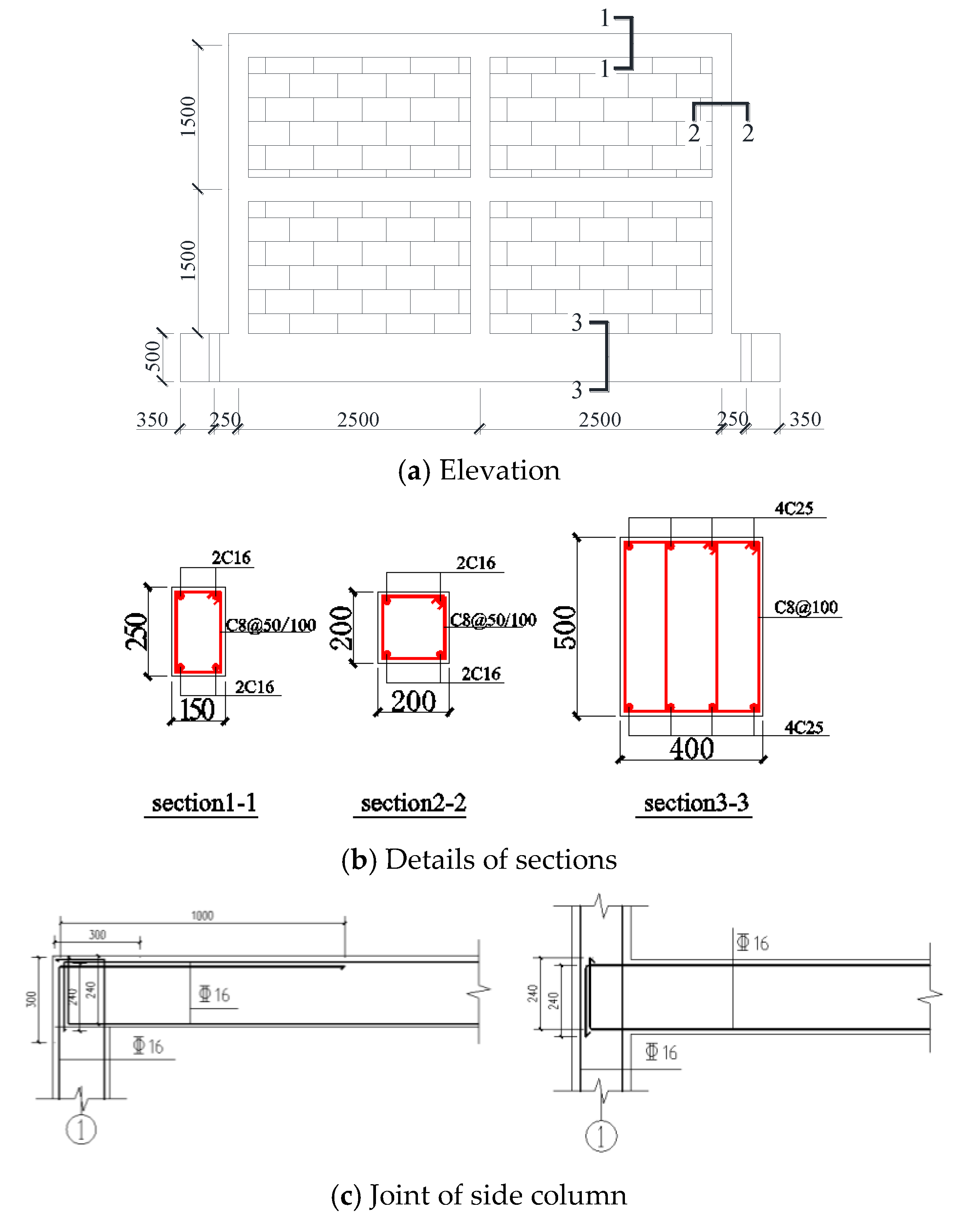
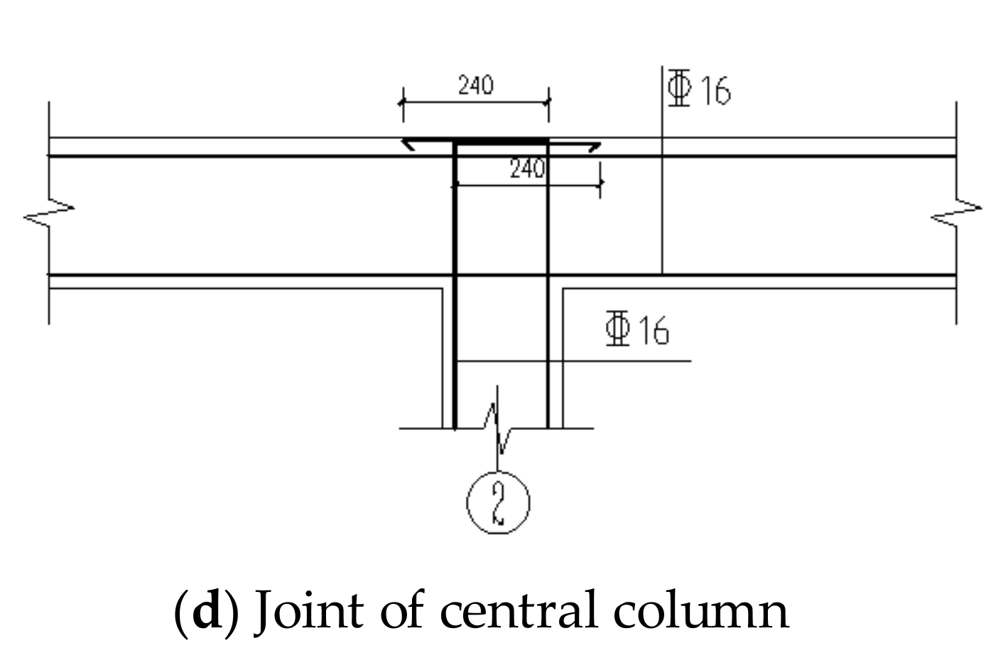
To investigate the similarities and differences of seismic performance of frame structures with different types of infill walls. The types of infills in [34] are similar to those in this experiment. Based on their design process of infilled frames, three identical reinforced concrete frames were designed and made according to Chinese codes GB 50011-2010 [35] and GB 50010-2010 [36] in the test, and the size and steel reinforcement details of the specimens are shown in Figure 1. The bearing capacity of the frame was checked according to the maximum loading capacity of the horizontal actuator in the laboratory. The reinforcement of the frame should meet the design principle of “strong column and weak beam, strong shear and weak bending, strong joint and weak member” by calculating the bending capacity and shear capacity of beams and columns. The seismic shear bearing capacity of the joint is required to be checked due to the failure of the joint should not occur before the failure of the member. The specimen has two stories and two spans, with the span of each bay and a story height of 2.5 m and 1.5 m, respectively. The section sizes of column and beam are 200 mm × 200 mm and 150 mm × 250 mm, respectively. The specimen was fixed by the foundation beam to simulate the restraint effect of the structural foundation, and the size of the foundation beam is 400 mm × 500 mm. To observe the failure mode of the infill walls and prevent the premature failure of the frame, the reinforcement of the frame was properly strengthened. Four HRB400 MPa rebars with a diameter of 16 mm were used in the longitudinal reinforcement of the beams and columns of the frames for each specimen, while eight HRB400 MPa rebars with a diameter of 25 mm were used as longitudinal reinforcement for the foundation beam.
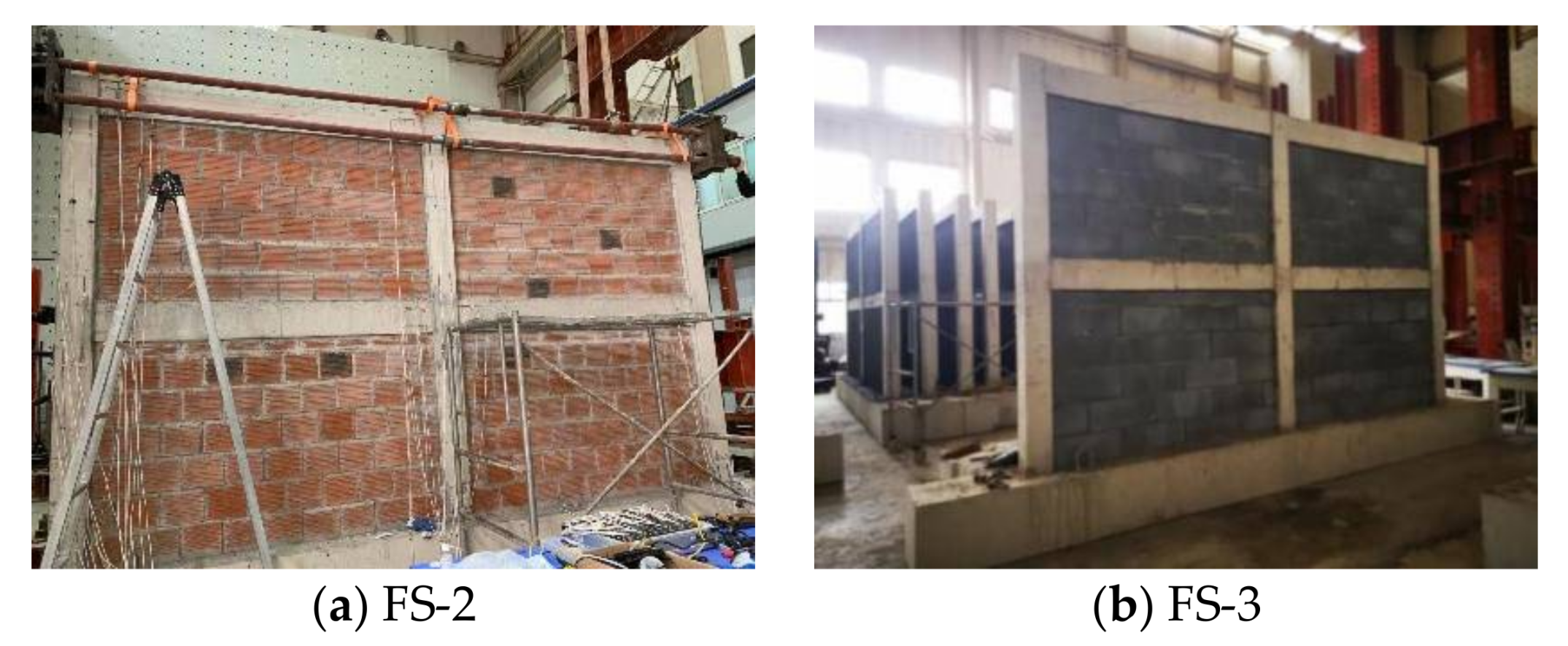
The main parameters of the test are whether to build infill walls and the different types of infill walls. The basic information of the test specimen is shown in Table 1. Specimen FS-1 was an empty frame as the control specimen, while FS-2 and FS-3 were built with clay air bricks and aerated lightweight concrete blocks (ALC), respectively. Before building the infill walls, two HPB300 MPa tie rebars with the diameter of 6 mm were set along the frame column every 500 mm to ensure the effective tie between the concrete frame structure and the infill walls and the out-of-plane stability of the infill walls, and the length of the tie rebar was 700 mm [37]. The tie bars were chemically anchored to the frame column with planting glue, and the anchorage depth is 70 mm. The infill walls were constructed by the method of staggered joints. Figure 2 shows the actual effect of the specimens after the completion of the construction of the infill walls.
2.2. Material Properties
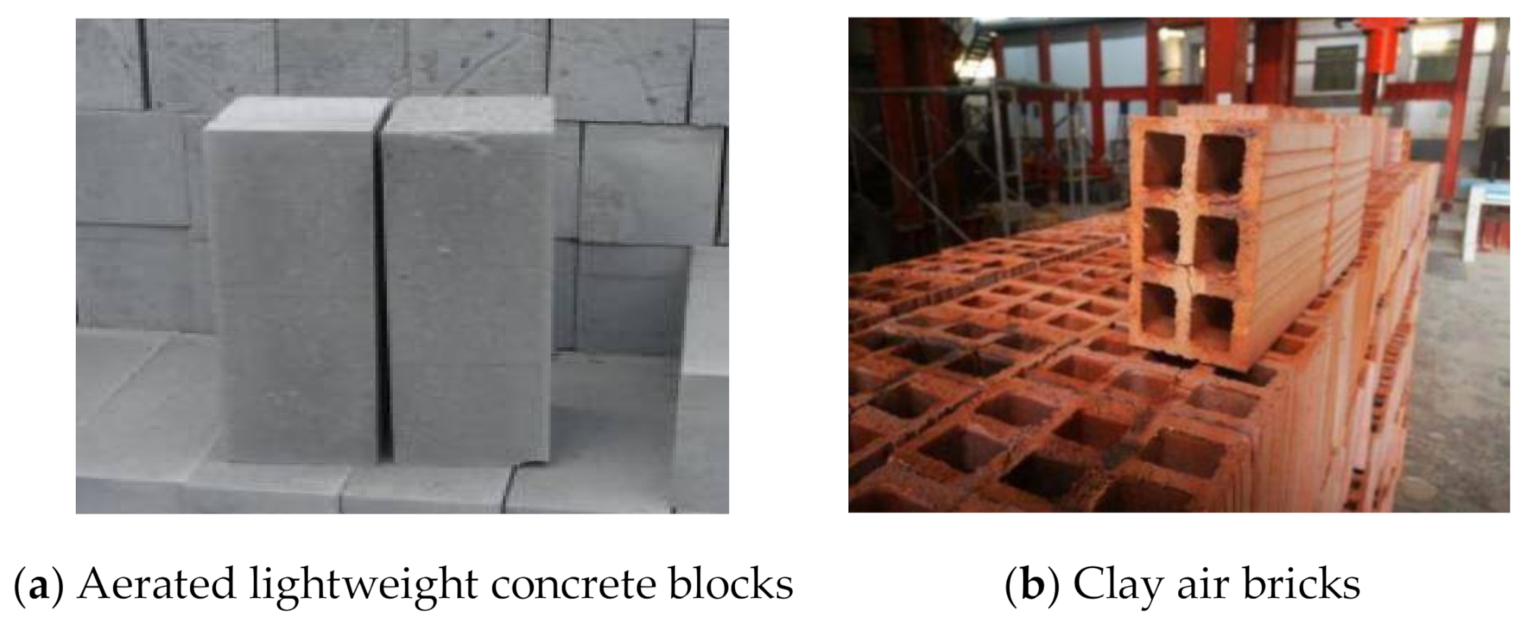
Due to the small size of the beam and column of the test specimen, and to facilitate the pouring of concrete, commercial fine aggregate concrete of strength grade C30 was used in the frame of the test specimen, while ordinary commercial concrete of strength grade C30 was used in the foundation beam, and the cube test blocks were preserved in the process of pouring concrete. The cube compressive strength of fine aggregate concrete of the frame and ordinary concrete is 31.5 MPa and 34.5 MPa respectively. The dimensions of clay hollow brick and aerated lightweight concrete block are 240 mm × 115 mm × 90 mm and 600 mm × 120 mm × 250 mm, respectively, as shown in Figure 3. The yield strength of longitudinal reinforcement and the stirrups of the beams and columns is 400 MPa.
2.3. Test Setup and Measurements
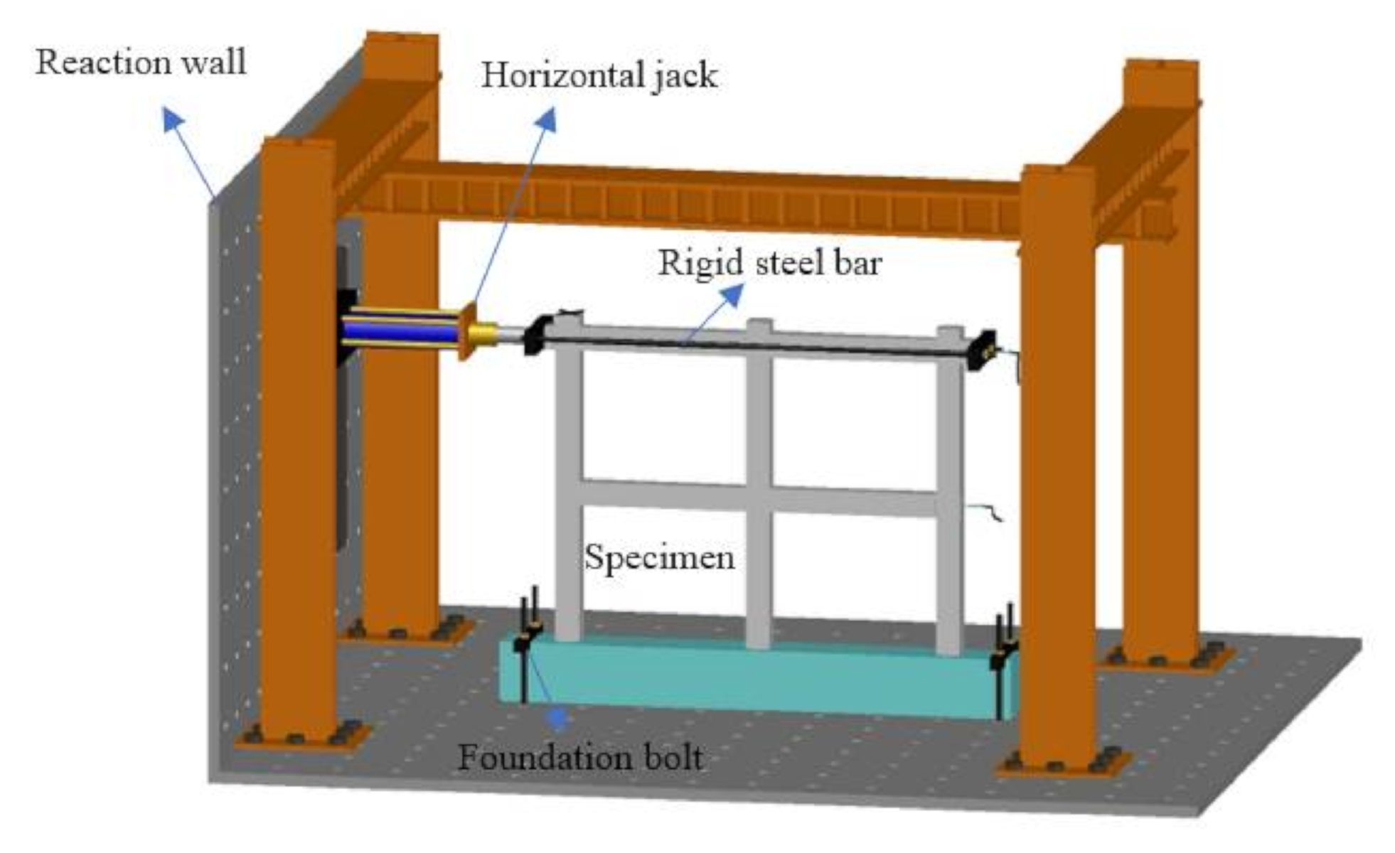
Figure 4 shows the schematic diagram of the test loading system. The specimen was firmly fixed on the ground through the foundation beams and anchor bolts. Due to the loading force in the first layer is relatively small if the inverted triangle loading mode is adopted, and the vertex loading mode has little effect on the test results. In view of the existing conditions in our laboratory, it is difficult to control two horizontal loading actuators at the same time, so we choose the vertex concentrated force loading mode. The low frequency cyclic horizontal load was applied to the second-floor beam of the frame through the electro-hydraulic servo system fixed on the reaction wall. The specimen was linked to the loading system by horizontal steel bars. No vertical load was applied during the test. In the absence of vertical load, the side column on one side of the frame would be in the tension state under the cyclic horizontal load, so the bending moment in the plastic hinge area of the column was relatively large, and the cracking of the column was relatively early, and the shear capacity would decrease to some extent. Although the lack of axial force will have a certain influence on the mechanical performance of the structure, considering that the main purpose of our test is to study the influence of infill wall on the seismic performance of the frame structure, the specimens with infill wall and without infill wall are all not applied with axial load, so we can still achieve our main purpose of the experiment.
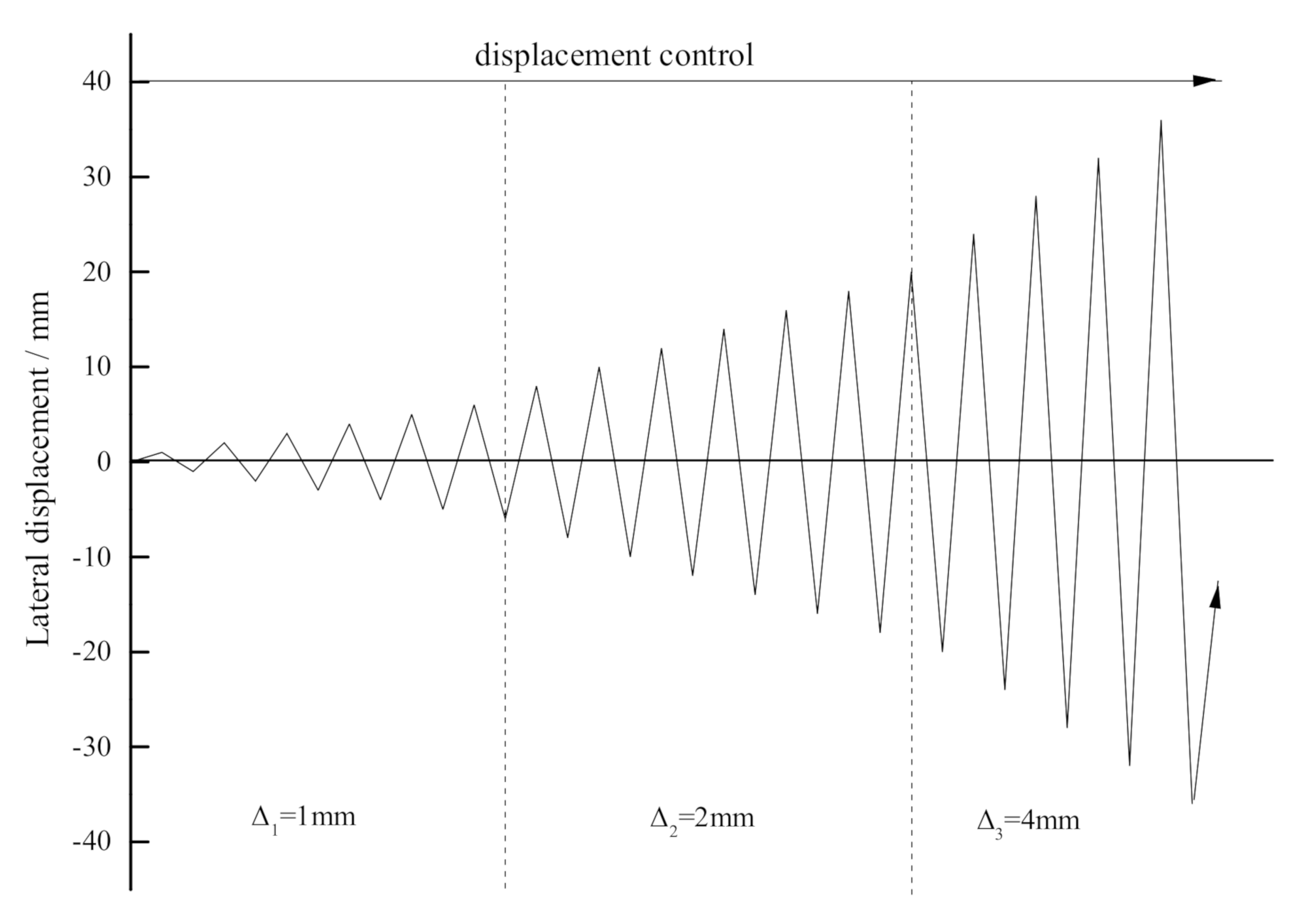
Figure 5 shows the schematic diagram of cyclic loading. The horizontal load was controlled by displacement during the test. The horizontal displacement of each loading stage increased by 1 mm before the drift ratio of 0.2%, and the horizontal displacement increased by 2 mm after the drift ratio of 0.2% according to the loading conditions of the field tests. The loading cycle at each stage corresponded to the loading displacements in the two directions of push and pull, in which the displacement of push was defined as positive loading and the pull was negative. The test was stopped when the horizontal load decreased to 85% of the peak load or the specimens were seriously damaged.
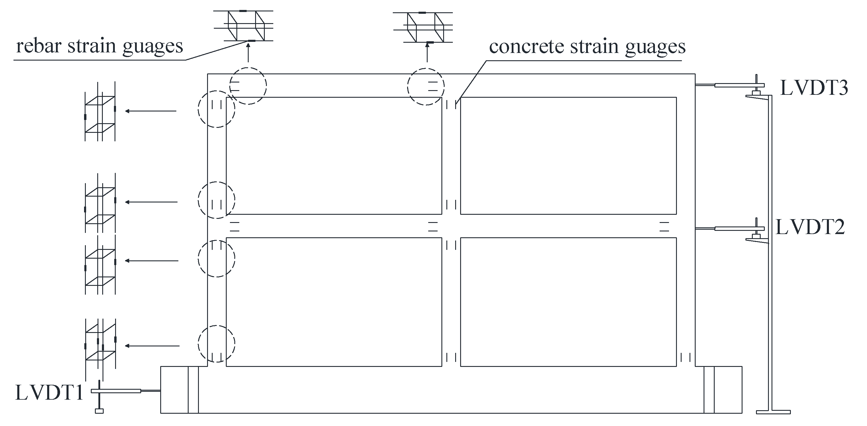
The corresponding load and displacement of the specimens at each stage were automatically collected and recorded by the electro-hydraulic servo loading system (MTS system). Because the specimen might slip or the connecting rigid bars connecting the specimen and the loading system deformed during the loading process, the displacement which was automatically collected by the loading system was not the actual displacement at the loading point of the specimen. Therefore, a displacement gauge was installed at the beam of the first-floor, second-floor and the foundation to accurately record the displacement of each floor and the slip of the specimen. For the frame structure, the end of the beam and column is the key location of the structure, so the strain gauges of steel and concrete were arranged at this part of the specimen. Strain gauges were arranged on four longitudinal rebars of the bottom section of the first-floor columns, and two strain gauges were arranged on the other control sections. The details of the measurement of the test are shown in Figure 6.
3. Test Results and Analysis
3.1. Experimental Observations
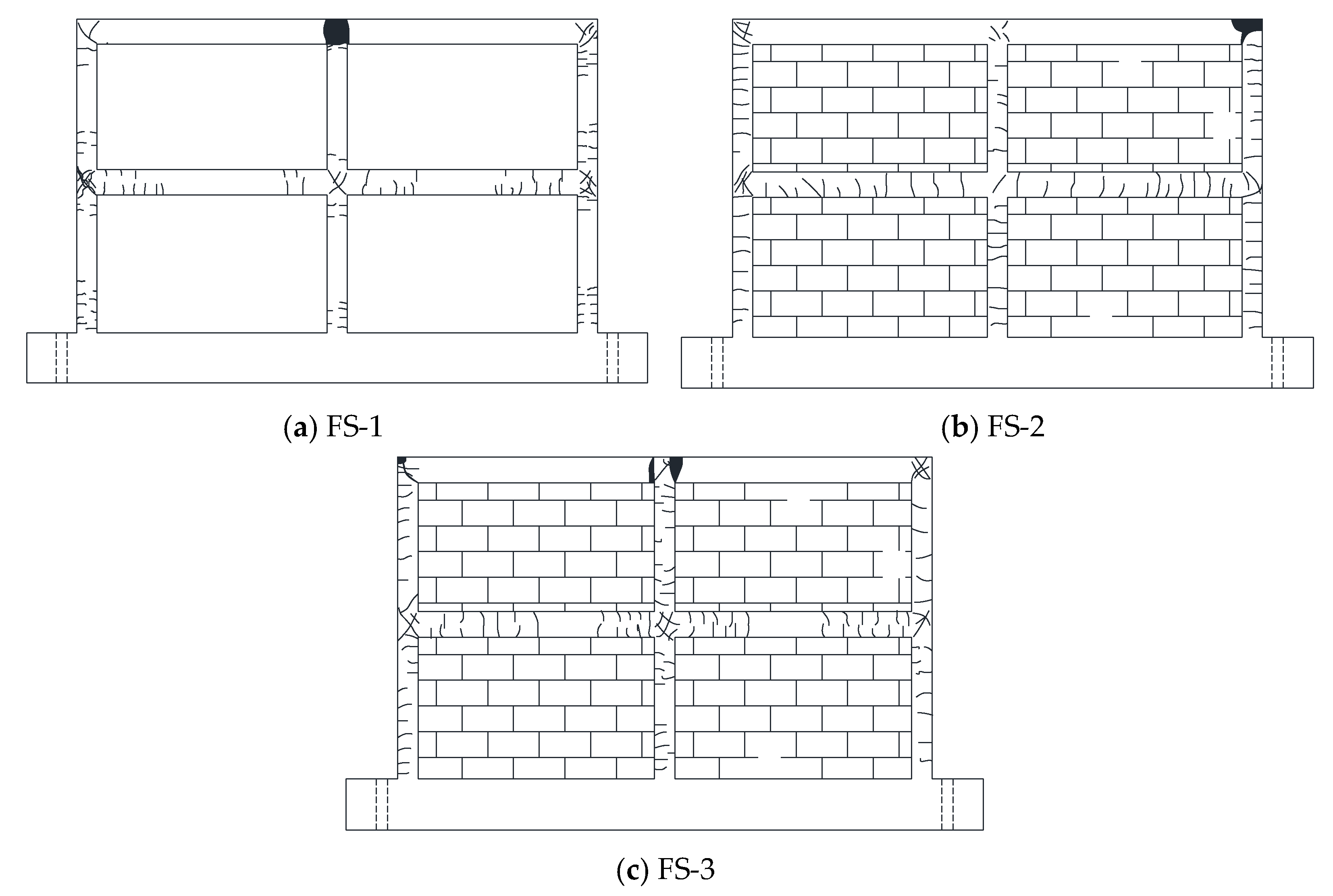
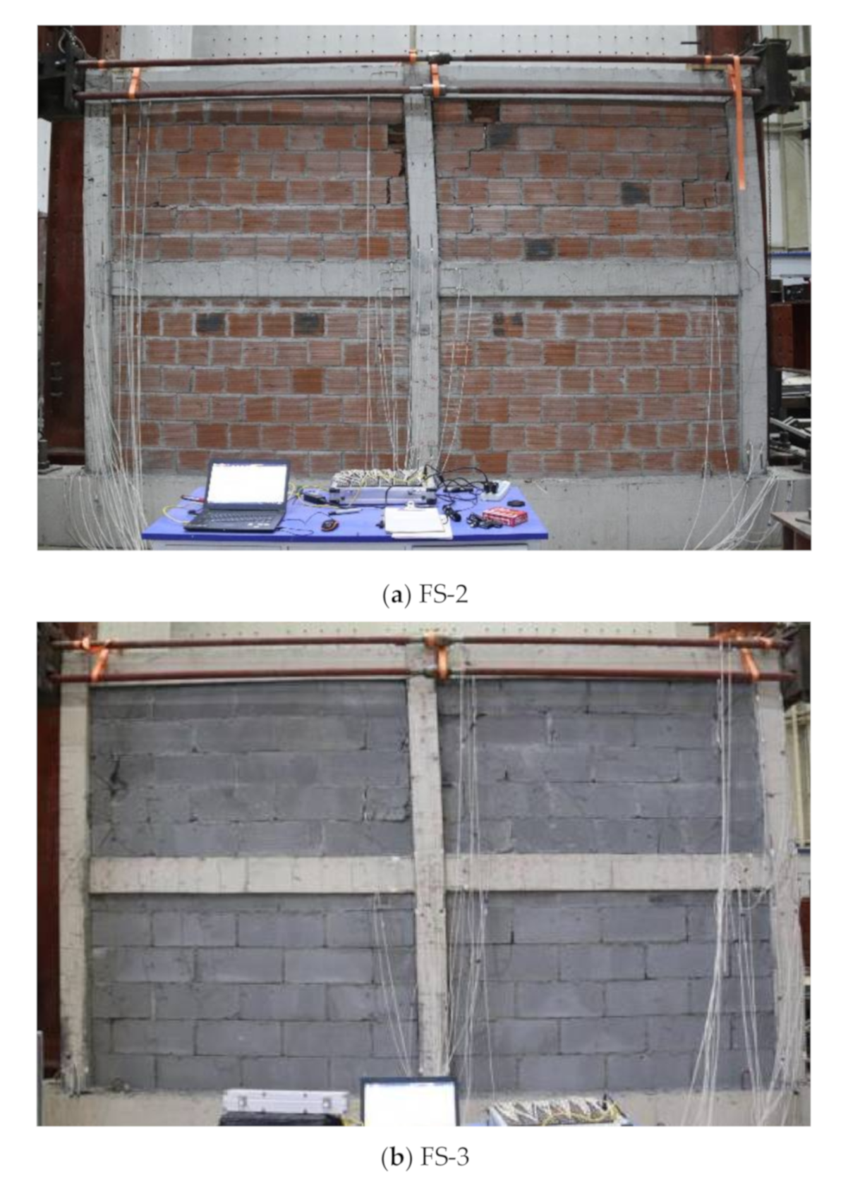
The final failure state of the frame structures and infill walls of the test specimens are shown in Figure 7 and Figure 8.
For the specimen FS-1 (i.e., empty frame structure without infill walls), the specimen conforms to the stress mode of the frame structure under horizontal load. Under the push and pull loads, the vertical and horizontal cracks at both ends of the beam and column appeared symmetrically. The overall deformation mode of the specimen was shear deformation, and the concrete at the beam end on both sides of the second floor central column joint of the specimen occurred flexural failure finally, at the same time, the concrete in the top core area of the central column of the second floor also fell off.
For the specimen FS-2 (i.e., the frame structure with infill walls of clay hollow brick), its stress mode was clearly different from that of the empty frame structure FS-1. When the loading displacement and load was 1 mm and 56.6 kN respectively, the main frame column began to crack. The horizontal cracks of the frame columns at both ends of the specimen appeared on the outside of the end columns and were evenly distributed along the column, rather than only at the end of the column as FS-1. For the beams of the frame, there were no obvious phenomena at the initial stage of loading, until the displacement and load were 9 mm and 200 kN, respectively. it might be due to the increase of the overall tensile area of the structure, the vertical cracks developed upward from the bottom of the beam began to appear at the end of the beams, instead of symmetrical at the top and bottom of the beams as FS-1. For the infill walls, at the displacement and load up to 3 mm and 135.6 kN, respectively, the clay hollow bricks began to crack near the columns of the second story. When the displacement and load reached at 9 mm and 202.7 kN, respectively, the columns of the frame were separated from the infill walls, step cracks initiated along the mortar joints of the second floor infill walls, and as the loading continued, the stepped cracks gradually penetrated along the wall. Part of the hollow bricks near the columns on the second floor would be broken when the displacement and load approached 23 mm and 199.6 kN, respectively. When the load dropped down to 85% of the peak load, a large number of masonry mortar joints of the second story infill walls were separated, and part of the hollow bricks near the columns of the walls were crushed off, but most of the hollow bricks in the middle of the infill walls were intact. However, the damage of the infill walls on the first floor was small, and the blocks did not appear obvious breakage or fell off. Finally, shear failure occurred in the beam-column joints and the top of the columns at the top of the specimen, and the deformation mode of the specimen was bending deformation.
For the specimen FS-3 whose infill walls were aerated lightweight concrete blocks, the stress mode was similar to that of FS-2 at the initial loading stage. When the loading displacement and load approached at 2 mm and 33.3 kN respectively, the columns of the frame began to crack. The horizontal cracks of the column appeared on the outside of the side column and distributed evenly along the column, and there were few cracks at the beam end. However, with the damage of the aerated lightweight concrete blocks, the stress mode of the specimen changed gradually. Compared with FS-2, whose infill walls were clay hollow bricks with high strength and stiffness, the vertical cracks at the beam end of the frame of FS-3 appeared earlier, and the horizontal cracks at the end of columns developed gradually, that is, the stress mode of the main frame structure was similar to that of the frame structure of FS-1 gradually. For the infill walls, the same as the specimen FS-2 was that the blocks near the column were crushed by the frame and fell off. The difference was that the infill walls of FS-2 cracked mainly along the mortar joints and the cracks did not penetrate the blocks of the infill walls. However, the cracks of the infill walls of FS-2 would penetrate through the blocks, resulting in a large number of blocks broken. Similarly, the damage of the infill walls on the first story was small. Finally, similar to the specimen FS-1, the beam ends on both sides of the central column occurred flexural failure, and the deformation mode was also bending deformation. The peak load of FS-3 was clearly less than that of FS-2, but still larger than that of FS-1.
Based on these observations, it can be concluded that:
(1) In the initial loading stage, the infill walls and the frame worked together as a whole to share the load, and its integrity and stiffness were increased greatly. The diagonal bracing effect formed by the infill walls changed the stress mode of the main frame structure. Especially for the clay hollow bricks with high strength and stiffness, its diagonal bracing effect was stronger, which might cause more serious damage to the main frame structure, leading to the shear failure of beam-column joints or the top of the columns in advance. For the relatively soft aerated lightweight concrete blocks, due to the low strength of the blocks, the diagonal bracing effect was relatively weak in the early stage, and the damage to the main frame was small. With the accumulation of damage to the infill walls, the infill walls would withdraw from the work gradually, and the stress mode of the main frame would return to the mode of the empty frame structure gradually.
(2) The existence of infill walls surely changed the deformation mode of the structure, and the ultimate deformation mode of the specimens with infill walls was bending deformation.
(3) The empty frame structure FS-1 cracked when the loading displacement approached 6 mm, while the specimens FS-2 and FS-3 with infill walls cracked when the loading displacement was 1 mm and 2 mm, respectively. And the cracking load of FS-2 and FS-3 was greater than that of FS-1. So the infill wall increased the seismic action of frame structure and made the main frame crack earlier because of the strong interaction between the infill walls and the frame.
(4) Because the strength and stiffness of aerated lightweight concrete blocks were far lower than that of clay hollow bricks, the failure modes of the infill walls were clearly different: the infill walls with aerated lightweight concrete blocks would form inclined cracks through the blocks during the failure process, and the blocks would be divided into pieces by a large number of inclined cracks and fell off eventually, and the failure was relatively mild. However, the cracks of infill walls with clay hollow bricks mainly developed along the mortar joints and rarely penetrated through clay bricks due to the strength of clay hollow brick was higher than that of mortar joints. However, the internal ribs of the hollow bricks would be damaged under large deformation of the structure, resulting in the spalling of hollow bricks, which might lead to potential safety hazards. The shear and slip failure of the walls along the mortar joints occurred eventually, and the failure process was relatively rapid. However, the failure location of the two kinds of infill walls was the same. Because the corresponding horizontal load was not applied on the first floor during the test, it might have certain influence on the damage degree of the first floor, that is, compared with applying the horizontal load on the first floor, the shear force of the first floor is relatively small when the horizontal load is not applied on the first floor, the damage degree of the first floor may be relatively low. The failure of the infill walls of the second floor was more serious than that of the first floor, and the damage of the blocks near the beams and columns of the frame was more serious.
3.2. Hysteresis Curves
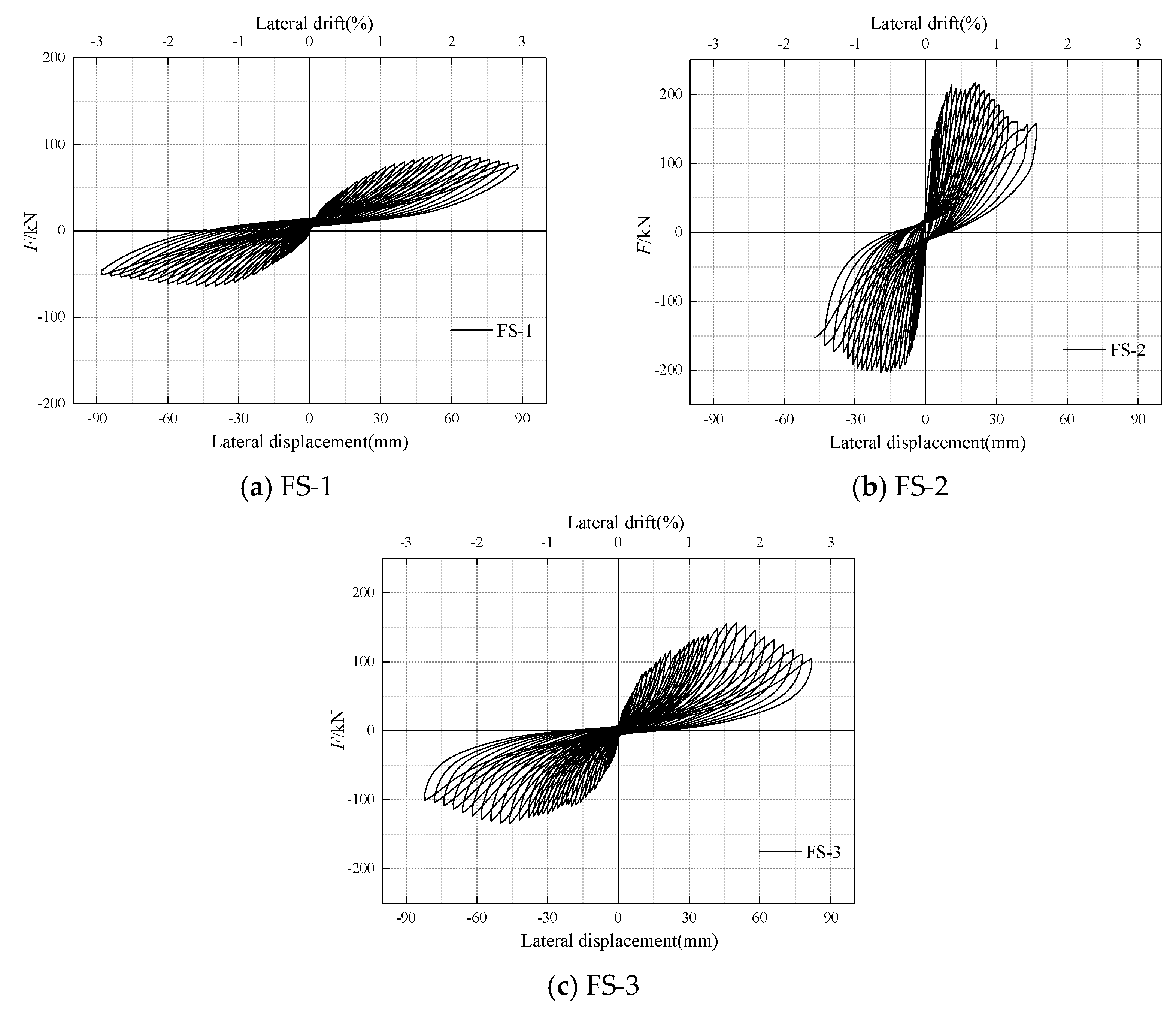
Figure 9 shows the hysteretic curves of the three specimens, where the ordinate represents the horizontal load and the abscissa represents the lateral drift and lateral displacement, respectively, which can be obtained from the hysteretic curves:
(1) For the specimen FS-1, its hysteretic curves presented typical characteristics of the frame structure. At the initial stage of loading, the hysteretic loops exhibited “Arch” shape. With the increase of lateral drift, the structure cracked and inclined cracks in the beam-column joints of the frame developed continuously. The shape of the hysteretic loop approached the “anti-s” shape gradually, and the fullness degree of the hysteretic loop was getting lower. The hysteretic curve was not plump, which means that the energy dissipation capacity was low. After the peak load, the bearing capacity of the specimen decreased slowly, showing a favorable deformation capacity.
(2) For the specimen FS-2, because the materials of the infill walls were clay hollow bricks with stronger strength and stiffness, the shape of its hysteretic loop was similar to the shuttle shape at the initial stage of loading, which means that the structure had strong energy dissipation capacity. However, with the increase of the loading displacement, the frame and the brick wall would crack when the lateral drift ratio reached 1/3000 due to the strong interaction between the infill walls and the frame, and the hysteresis loop would turn to the “anti-s” shape gradually, which indicates that the specimen had suffered a certain shear damage. Because of the high stiffness of the infill walls, the hysteretic curve was close to the ordinate, that is, the initial stiffness was larger, the bearing capacity rises rapidly, and the peak bearing capacity is higher. However, with the shear slip of mortar joints and the shear failure of the RC frame structure after reaching the peak load, the overall bearing capacity of the specimen decreased rapidly, showing a poor deformation capacity.
(3) For specimen FS-3, due to the existence of the infill walls, the shape of the hysteretic loop was similar to the “arch” shape at the initial loading stage, which was relatively full compared with FS-1, indicating that the energy dissipation capacity was stronger. However, compared with FS-2, the strength and stiffness of the infill walls were lower, and the initial stiffness and rise speed of bearing capacity were both lower. However, the overall deformation ability of the specimen was enhanced, and the failure rate was slower.
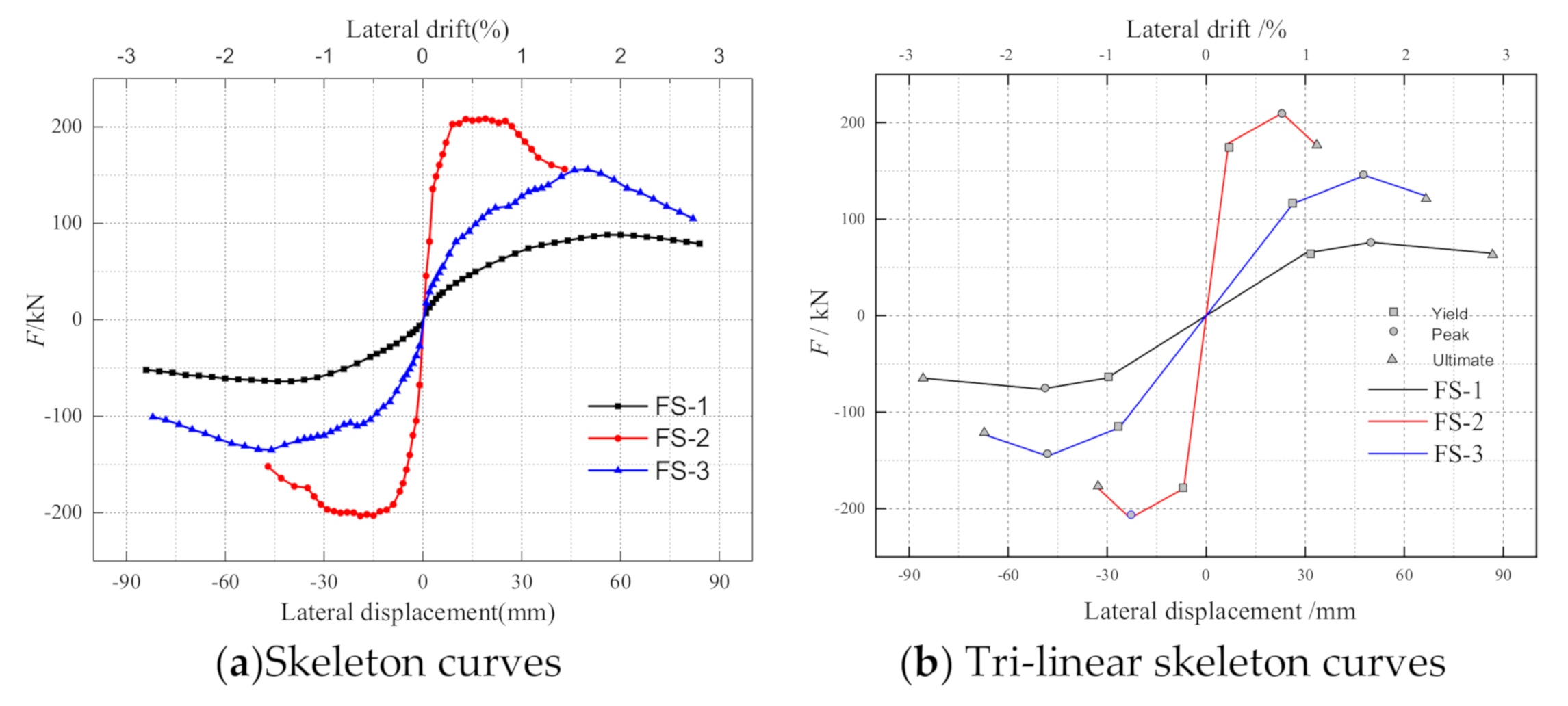
3.3. Skeleton Curves and Lateral Strength
Figure 10a shows the skeleton curves of the three specimens (i.e., the line connecting the peak points of the hysteretic curves of each stage), and the key points on the skeleton curve (i.e., yield point, peak point and ultimate point) are listed in Table 2. To reduce the error of the test results, the load displacement values of each key point are taken as the average values of the two loading directions. The ultimate displacement Δu is taken as the displacement when the bearing capacity of the specimen decreases to 85% of the peak bearing capacity, and the yield displacement Δy is obtained by the energy equivalent method [38] according to the skeleton curve of the specimen. Based on the above key points, Tri-linear of skeleton curves were drawn, as shown in Figure 10b. Through Figure 10 and Table 2, it can be revealed the following results:
(1) Infill wall increased the bearing capacity of the reinforced concrete frame structures. The increase of bearing capacity varied with the type of infill wall. The peak load of FS-2 filled with clay hollow brick was 175.8% higher than that of FS-1. The peak load of FS-3 was 91.1% higher than that of FS-1.
(2) The infill wall had an obvious stiffness effect on the frame structure, which greatly increased the overall stiffness of the frame structure. The overall stiffness of the specimen increased greatly and the horizontal load increased rapidly due to the high strength and stiffness of the infill walls of FS-2. However, when the load approached the peak load, due to the damage accumulation of hollow brick blocks and the shear slip failure of mortar joints, the stiffness effect of the infill wall decreased rapidly. The load decreased rapidly, and the corresponding ultimate displacement was the smallest of the three specimens, which showed poor deformation capacity. For the specimen FS-3 with relatively weak strength and stiffness of the infill walls, the growth rate of horizontal load was between FS-1 and FS-2 at the same loading drift ratio. After reaching the peak load, its bearing capacity decreased slowly, and the ultimate displacement was 1.88 times that of FS-2 and 0.83 times that of FS-1. Therefore, the frame structure with relatively weak infill walls showed favorable deformation ability.
(3) The yield displacement of the structure decreased with the increase of the strength of the infill walls, and the yield displacement of specimen FS-2 was only 22.6% of that of FS-1. The reasons are analyzed as follows: Under the same lateral drift, compared with the empty frame FS-1, the specimen with infill walls bore more horizontal load because of the stiffness effect of the infill walls. The diagonal braces formed by the infill walls in the frame changed the internal force distribution of the frame and bore most of the shear force, which would cause damage to the beam-column joints and the top of the columns. And with the failure of the infill walls, most of the load was borne by the frame, which made the frame yield earlier.
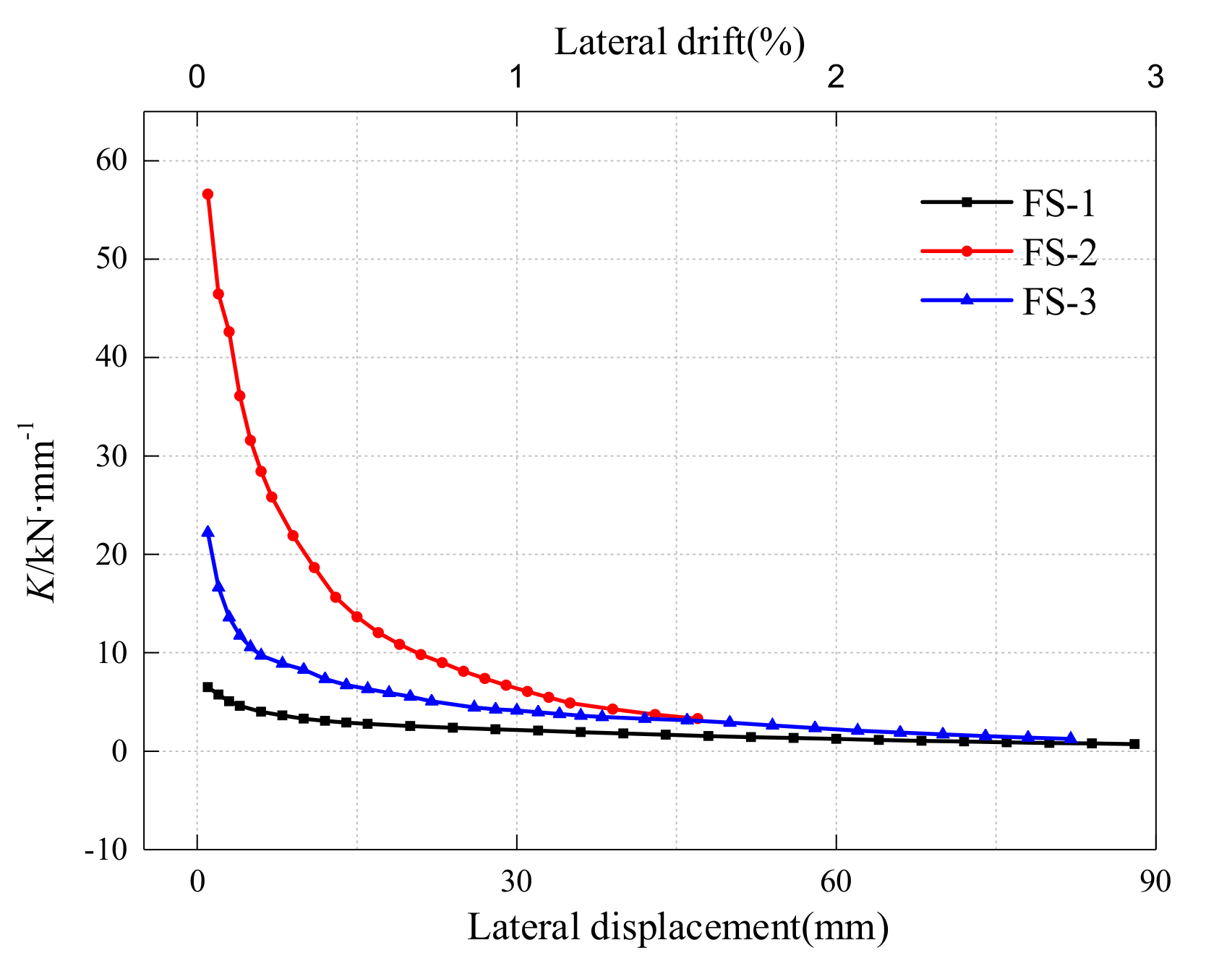
3.4. Stiffness Degradation
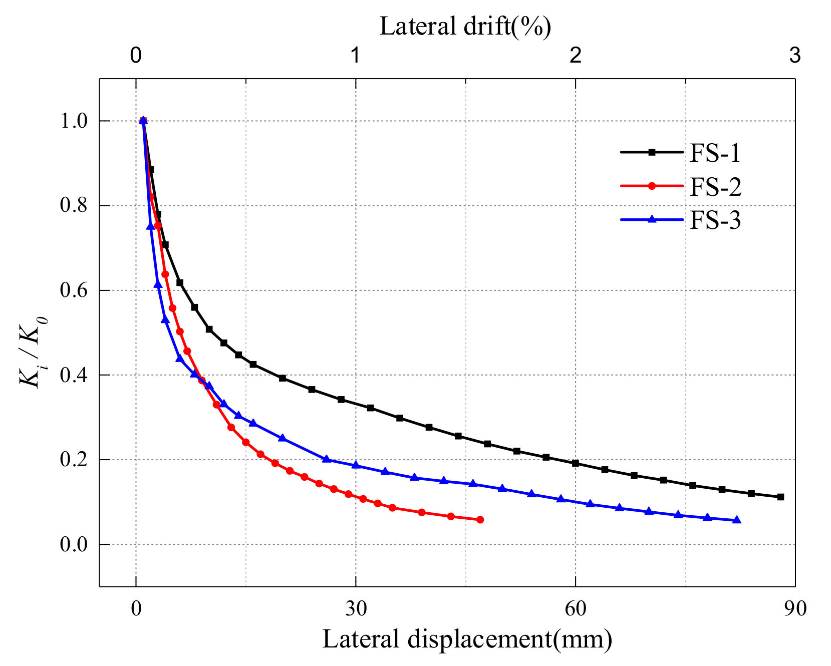
Figure 11 shows the secant stiffness of each specimen under different loading displacement levels. The abscissa represents the horizontal loading displacement and lateral drift, and the ordinate represents the secant stiffness Ki of each loading level. Secant stiffness is defined as: , where +Fi and -Fi represent the positive and negative horizontal load of each stage, respectively, and +Δi and −Δi represent the positive and negative horizontal displacement of each stage respectively. Figure 12 shows the stiffness degradation rate of each specimen during loading. The abscissa is the loading displacement and loading lateral drift, the ordinate is the stiffness degradation ratio Ki/K0, and K0 is the initial stiffness. Based on Figure 9 and Figure 10, some observations can be summed up as follows:
(1) The infill wall had an obvious stiffness effect, and the overall stiffness of the frame structure was significantly improved by the infill walls. The initial stiffness of FS-2 and FS-3 with infill walls was 8.7 and 3.4 times that of FS-1, respectively. However, the increase of stiffness was positively correlated with the strength of the infill wall. The initial stiffness of the specimen FS-2 was 2.5 times that of FS-3 due to the higher strength of the infill walls of the specimen FS-2.
(2) In the initial stage of loading (i.e., before the loading lateral drift is about 0.5%), all specimens showed a faster rate of stiffness degradation. The stiffness degradation rate of the specimen FS-2 and FS-3 was faster than that of the specimen FS-1 without infill walls. Before the loading displacement was about 10 mm, because of the smaller strength of the infill walls of FS-3, the damage of the infill walls was more serious, and the stiffness degradation of the whole specimen was faster. After the loading displacement approached 10 mm, the stiffness degradation rate of the specimen FS-2 exceeded FS-3 due to the shear slip of the mortar joints and the accumulation of the damage of the infill walls.
(3) At the later stage of loading (after the lateral drift up to 1.5%), the secant stiffness of the frame structure with infill walls was the same as that of the empty frame structure gradually. This is because, with the destruction of the infill walls, the infill walls withdrew from working with the frame gradually, and the horizontal load was borne by the frame gradually. Therefore, the secant stiffness and the degradation rate of the three specimens approached gradually in the later stage of loading.
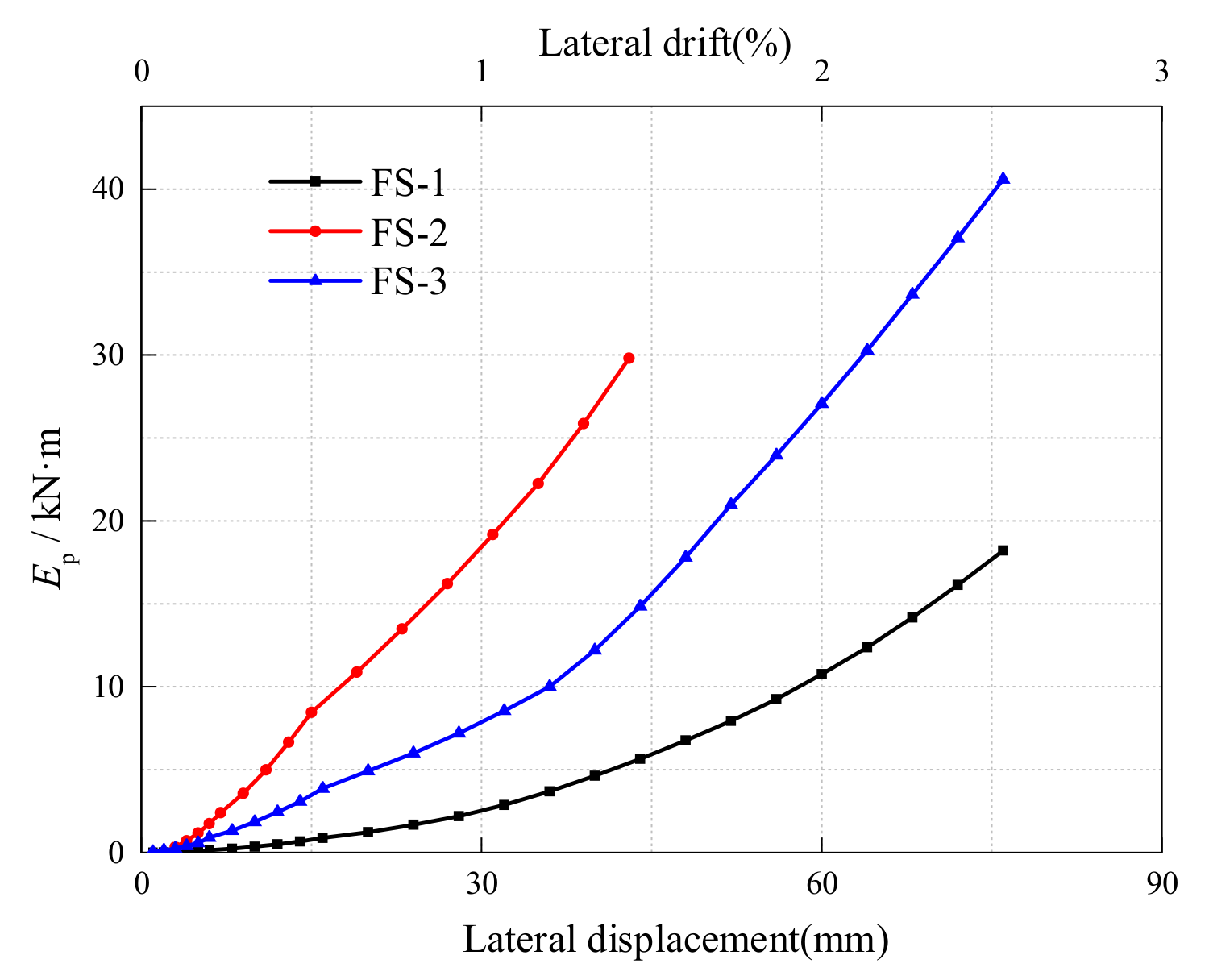
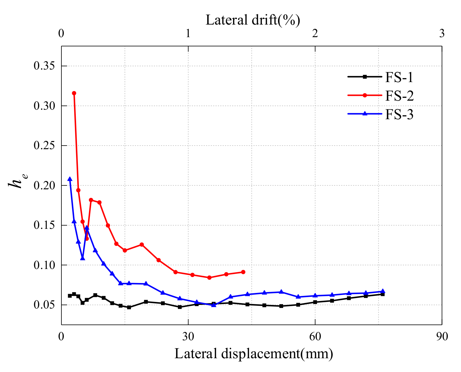
3.5. Energy Dissipation Capacity
The energy consumption of the structure is synthetically reflected by the two parameters shown in Figure 13 and Figure 14 (i.e., cumulative energy dissipation EP and equivalent viscous damping coefficient he). Among them, Ep is the sum of the hysteresis loop areas of each stage before the current loading displacement, which can evaluate the energy consumption of the structure under a certain loading displacement. he is calculated according to the Chinese code JGJ/T101-2015 [39], which represents the ratio between the energy consumed by each hysteresis loop and the input energy, which can reflect the energy dissipation capacity of the structure under each loading level. From Figure 13 and Figure 14, it can be observed that:
(1) The results show that the infill walls took part in the hysteretic energy dissipation of the frame structure, and the cumulative energy dissipation of the frame structure with infill walls was higher than that of the empty frame structure, and different types of infilled had different degrees of improvement on the cumulative energy dissipation of the masonry-infilled frame structure. For example, under the loading lateral drift of 1.5%, the cumulative energy consumption of FS-2 was 5.2 times that of FS-1, and the cumulative energy consumption of FS-3 was 2.6 times that of FS-1.
(2) In the early stage of loading, the infill walls increased the viscous damping coefficient of the frame structure greatly. The initial equivalent viscous damping coefficients of FS-2 and FS-3 were 5 times and 2.4 times of FS-1, respectively. However, at the initial stage of loading, the equivalent viscous damping coefficient of the frame with infill walls decreased rapidly because of the cracking of the infill walls, that is, the energy dissipation capacity decreased rapidly. In the later stage of loading, with the failure of the infill walls, the infill walls withdrew from participating in energy dissipation gradually, and the equivalent viscous damping coefficients of FS-2 and FS-3 became stable and close to the empty frame structure FS1 gradually, that is, the specimen dissipated energy mainly through the main frame in the later stage of loading. Especially for specimen FS-3 with softer infill walls, its equivalent viscous damping coefficient (i.e., energy dissipation capacity) was close to FS-1 in the later stage.
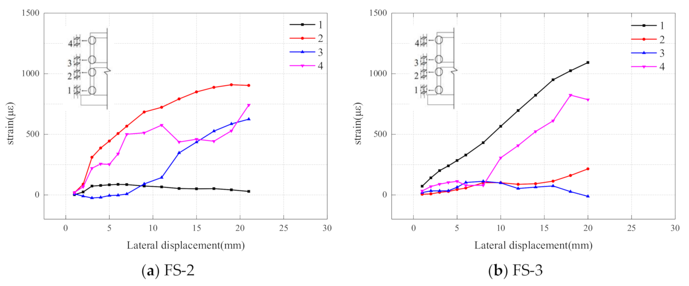
3.6. Analysis of Mechanical Mechanism
It can be found that in the early stage of loading, the crack form of the side column of FS-2 and FS-3 was different clearly from that of FS-1. Therefore, in Figure 15, the strain of the longitudinal steel bars at the bottom and top of the side columns of the first and second story frame at the early stage of loading was extracted to analyze its stress mechanism qualitatively. As we all know, for the frame structure, the column has a reverse bending point under the action of horizontal load. If the same longitudinal reinforcement of the column is in tension at the bottom section of the column, then it is in compression at the top section of the column. It can be seen from Figure 15, the stress of the four measuring points of one longitudinal rebar of the side column was positive at the initial stage of loading, that is, the longitudinal reinforcement was in tension along the full length, which was clearly different from the stress state of the longitudinal reinforcement of the ordinary frame column under horizontal load.
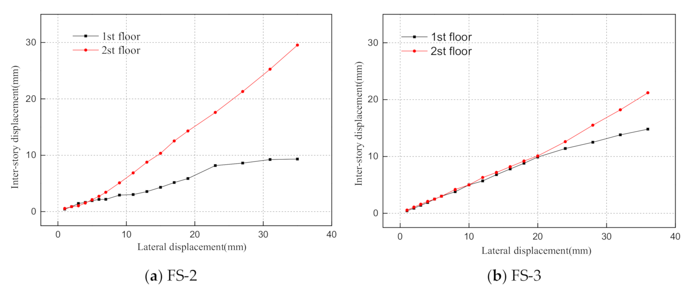
Based on the above experimental phenomena and the stress state of the column reinforcement, it can be observed that: in the early stage of loading, the two frames with infill walls (i.e., FS-2 and FS-3) had a similar mechanical mechanism. Under the action of horizontal load, one side of the specimen was in tension and the other side was in compression. The columns of the frame on both sides of the specimen were similar to the edge restraint members of shear wall, and there was no reverse bending point on the columns. The horizontal cracks of the columns were distributed along the columns evenly, and the cracking of the columns was earlier than that of the beams. The infill walls formed diagonal braces in the frame and bore most of the shear force. At the same time, as shown in Figure 16, the interstory displacement of the second floor was larger than that of the first floor, and the overall deformation was no longer the type of shear, but an obvious type of bending deformation similar to that of shear wall structure. Therefore, the overall stress mechanism might be similar to the shear wall structure in the early stage of loading. For the infill walls of clay hollow bricks, the diagonal bracing effect would be more obvious, and it will cause more serious damage to the top of the columns and beam-column joints of the main frame. Finally, the shear failure of the columns and joints would occur prematurely. For the infill walls of aerated lightweight concrete blocks, it would exit from working with the frame quickly because of its lower strength and the more rapid damage, and the main frame would work alone, and the stress mode would change into the stress mode of the empty frame structure gradually. Compared with the specimen FS-2, because of the relatively weak infill walls of the specimen FS-3, the damage of the main frame structure of the specimen FS-3 was slighter at the initial stage. The specimen FS-3 was the ductile failure of the plastic hinge at the end of the beam. The failure rate of the specimen FS-3 was slower and showed better deformability.
4. Conclusions
Two RC frames with infill walls and one without infill walls were designed to study the influence of infill wall on the mechanical mechanism of frame structure and the me-chanical mechanism of different types of masonry infilled frames. Through the analysis of the above test results, the conclusions can be summarized as follows:
(1) The infill walls significantly improved the initial stiffness, horizontal bearing ca-pacity and the hysteretic energy consumption of the frame structure. The improvement was positively correlated with the strength of the blocks of the infill walls.
(2) Under the action of earthquake horizontal load, the stiffness and the energy con-sumption capacity of the masonry-infilled frames degraded rapidly and approached the empty frame structure gradually with the failure of the infill walls.
(3) The infill walls changed the mechanical mechanism of the frame structure. The stress mechanism of the masonry frame structure was similar to the shear wall structure. The infill walls and the frame worked together and the infill walls formed diagonal braces inside the frame to share most of the shear force. The overall deformation mode of the frame with infill walls was bending deformation. With the failure of the infill walls, the infill walls would exit from working with the framework, and the stress mode would change into the stress mode of the empty frame structure gradually.
(4) The columns and beam-column joints of the masonry infilled frame suffered more serious damage due to the stronger diagonal bracing effect of the infill, which significantly reduced its yield displacement. The top of the columns and the joints were damaged prematurely by shear force, showing poor performance of deformation and ductility, which was unfavorable for seismic behavior.
(5) For softer material of infill wall such as aerated concrete block, the blocks would be divided into pieces by a large number of inclined cracks and even be crushed more easily by the frame. It has weaker interaction with the frame. Therefore, it is suggested to use relatively soft material for the infill walls and soft (or flexible) connections should be applied between the frame and the infill walls to reduce the interaction between the infill walls and the frame and the damage to the frame structure.
Author Contributions
F.W.: Methodology, Formal analysis, Investigation, Writing—original draft, Writing—review & editing, Visualization. K.Z.: Conceptualization, Writing—review & editing, Project administration. J.Z.: Conceptualization, Methodology, Visualization. K.Y.: Conceptualization, Writing—review & editing. All authors have read and agreed to the published version of the manuscript.
Funding
This research was funded by National Key Research and Development Plan of China (No. 2017YFC0806100).
Data Availability Statement
The data used to support the findings of this study are included within the article. The original details of the data presented in this study are available on request from the corresponding author.
Conflicts of Interest
The authors declare no conflict of interest. The funders had no role in the design of the study; in the collection, analyses, or interpretation of data; in the writing of the manuscript, or in the decision to publish the results.
References
- Dimova, S.L.; Negro, P. Seismic assessment of an industrial frame structure designed according to Eurocodes. Part 2: Capacity and vulnerability. Eng. Struct. 2005, 27, 724–735. [Google Scholar] [CrossRef]
- Dimova, S.L.; Negro, P. Seismic assessment of an industrial frame structure designed according to Eurocodes. Part 1: Experimental tests and their numerical simulation. Eng. Struct. 2005, 27, 709–723. [Google Scholar] [CrossRef]
- Chaker, A.A.; Cherifati, A. Influence of masonry infill panels on the vibration and stiffness characteristics of R/C frame buildings. Earthq. Eng. Struct. Dyn. 2015, 28, 1061–1065. [Google Scholar] [CrossRef]
- Civil and Structural Group of Tsinghua University; Xi’nan Jiaotong University; Beijing Jiaotong University. Analysis on building seismic damage in Wenchuan earthquake. J. Build. Struct. 2008, 29, 1–9. [Google Scholar]
- Yan, P.L.; Sun, B.T.; Zhang, H.Y. Seismic damage to RC frame teaching building in Lushan MS7.0 earthquake. China Civil. Eng. J. 2014, 47, 24–28. [Google Scholar]
- Ricci, P.; De Risi, M.T.; Verderame, G.M.; Manfredi, G. Influence of infill distribution and design typology on seismic performance of low- and mid-rise RC buildings. Bull. Earthq. Eng. 2013, 11, 1585–1616. [Google Scholar] [CrossRef]
- Qian, K.; Li, B. Effects of Masonry Infill Wall on the Performance of RC Frames to Resist Progressive Collapse. J. Struct. Eng. 2017, 143, 04017118. [Google Scholar] [CrossRef]
- Mosalam, K. Seismic Evaluation of Reinforced Concrete Buildings Including Effects of Masonry Infill Walls; University of California: Berkeley, CA, USA, 2007. [Google Scholar]
- Baghi, H.; Oliveira, A.; Valença, J.; Cavaco, E.; Neves, L.; Júlio, E. Behavior of reinforced concrete frame with masonry infill wall subjected to vertical load. Eng. Struct. 2018, 171, 476–487. [Google Scholar] [CrossRef]
- Schneider, S.P.; Zagers, B.R.; Abrams, D.P. Lateral strength of steel frames with masonry infills having large openings. J. Struct. Eng. 1998, 124, 896–904. [Google Scholar] [CrossRef]
- Flanagan, R.D.; Bennett, R.M. In—Plane behavior of structural clay tile infilled frames. J. Struct. Eng. 1999, 125, 590–599. [Google Scholar] [CrossRef]
- Abrams, D.P.; Angel, R.; Uzarski, J. Out-of-Plane Strength of Unreinforced Masonry Infill Panels. Earthq. Spectra 2012, 12, 825–844. [Google Scholar] [CrossRef]
- Dafnis, A.; Kolsch, H.; Reimerdes, H.G. Arching in Masonry Walls Subjected to Earthquake Motions. J. Struct. Eng. 2002, 128, 153–159. [Google Scholar] [CrossRef]
- Henderson, R.C.; Fricke, K.E.; Jones, W.D.; Beavers, J.E.; Bennett, R.M. Summary of a Large- and Small-Scale Unreinforced Masonry Infill Test Program. J. Struct. Eng. 2003, 129, 1667–1675. [Google Scholar] [CrossRef]
- Mallick, D.V.; Severn, R.T. The behaviour of infilled frames under static loading. Proc. Inst. Civil Eng. 1967, 38, 639–656. [Google Scholar] [CrossRef]
- Fiorato, A.E.; Sozen, M.A.; Camble, W.L. An Investigation of the Interaction of Reinforced Concrete Frames with Masonry Fillers Walls; University of Illinois: Champaign, IL, USA, 1970. [Google Scholar]
- Govindan, P.; Lakshmipathy, M.; Santhakumar, A.R. Ductility of lnfilled Frames. Moenia Rev. Lucense Lingüistica Lit. 1986, 83, 41–49. [Google Scholar]
- AL-Chaar, G.; Issa, M.; Sweeney, S. Behavior of Masonry-Infilled Nonductile Reinforced Concrete Frames. J. Struct. Eng. 2002, 128, 1055–1063. [Google Scholar] [CrossRef]
- Zhou, X.J. Study on Seismic Behavior of Flexible Connection Frame Structure Infilled with New Masonry; Tianjin University: Tianjin, China, 2014. [Google Scholar]
- Li, D.Y. Study on Seismic Performance of New Masonry Infill Wall under Different Connection form; Hunan University: Changsha, China, 2016. [Google Scholar]
- Jiang, H.; Mao, J.; Liu, X. Experimental study on seismic performance of masonry infilled RC frame with different types of connections. J. Build. Struct. 2014, 35, 60–67. [Google Scholar]
- Mehrabi, A.B.; Benson Shing, P.; Schuller, M.P.; Noland, J.L. Experimental Evaluation of Masonry-Infilled RC Frames. J. Struct. Eng. 1996, 122, 228–237. [Google Scholar] [CrossRef]
- Kakaletsis, D.J.; Karayannis, C.G. Influence of Masonry Strength and Openings on Infilled R/C Frames Under Cycling Loading. J. Earthq. Eng. 2008, 12, 197–221. [Google Scholar] [CrossRef]
- Zovkic, J.; Sigmund, V.; Guljas, I. Cyclic testing of a single bay reinforced concrete frames with various types of masonry infill. Earthq. Eng. Struct. Dyn. 2013, 42, 1131–1149. [Google Scholar] [CrossRef]
- Kakaletsis, D.; Karayannis, C. Experimental investigation of infilled r/c frames with eccentric openings. Struct. Eng. Mech. 2007, 26, 231–250. [Google Scholar] [CrossRef]
- Kakaletsis, D.J.; Karayannis, C.G. Experimental Investigation of Infilled Reinforced Concrete Frames with Openings. ACI Struct. J. 2009, 106, 132–141. [Google Scholar]
- Tasnimi, A.A.; Mohebkhah, A. Investigation on the behavior of brick-infilled steel frames with openings, experimental and analytical approaches. Eng. Struct. 2011, 33, 968–980. [Google Scholar] [CrossRef]
- Mansouri, A.; Marefat, M.S.; Khanmohammadi, M. Experimental evaluation of seismic performance of low-shear strength masonry infills with openings in reinforced concrete frames with deficient seismic details. Struct. Des. Tall Spec. Build. 2014, 23, 1190–1210. [Google Scholar] [CrossRef]
- Zhai, C.; Kong, J.; Wang, X.; Chen, Z. Experimental and Finite Element Analytical Investigation of Seismic Behavior of Full-Scale Masonry Infilled RC Frames. J. Earthq. Eng. 2016, 20, 1171–1198. [Google Scholar] [CrossRef]
- AL-Chaar, G.; Lamb, G.E.; Issa, M.A. Effects of openings on structural performance of unreinforced masonry infilled frames. ACI Spec. Publ. 2003, 211, 247–262. [Google Scholar]
- Yekrangnia, M.; Asteris, P.G. Multi-Strut Macro-Model for Masonry Infilled Frames with Openings. J. Build. Eng. 2020, 32, 101683. [Google Scholar] [CrossRef]
- Sigmund, V.; Penava, D. Influence of Openings, With and Without Confinement, on Cyclic Response of Infilled R-C Frames—An Experimental Study. J. Earthq. Eng. 2014, 18, 113–146. [Google Scholar] [CrossRef] [Green Version]
- Davorin, P.; Sarhosis, V.; Kozar, I.; Guljas, I. Contribution of RC columns and masonry wall to the shear resistance of masonry infilled RC frames containing different in size window and door openings. Eng. Struct. 2018, 172, 105–130. [Google Scholar]
- Schwarz, S.; Hanaor, A.; Yankelevsky, D.Z. Experimental Response of Reinforced Concrete Frames with AAC Masonry Infill Walls to In-plane. Cycl. Load. Struct. 2015, 3, 306–319. [Google Scholar] [CrossRef]
- GB 50010-2010, Code for Design of Concrete Structures; China Ministry of Construction: Beijing, China, 2015. (In Chinese)
- GB 50011-2010 Code for Seismic Design of Buildings; China Ministry of Construction: Beijing, China, 2015. (In Chinese)
- GB 50954-2014 Code for Construction of Masonry Structures Engineering; China Ministry of Construction: Beijing, China, 2014. (In Chinese)
- Park, R. Evaluation of ductility of structures and structural assemblages from laboratory testing. Bull. N. Z. Nat. Soc. Earthq. Eng. 1989, 22, 155–166. [Google Scholar] [CrossRef]
- JGJ/T101-2015 Specification for Seismic Test of Buildings; China Architecture & Building Press: Beijing, China, 2015. (In Chinese)
Figure 1.
Geometry and reinforcement details of specimens.


Figure 2.
Specimens with infill walls.

Figure 3.
Blocks of infill wall.

Figure 4.
Schematic diagram of the test loading system.

Figure 5.
Loading protocol.

Figure 6.
Details of the measurement.

Figure 7.
Crack patterns of frames.

Figure 8.
Crack patterns of infill walls.

Figure 9.
Hysteresis curves.

Figure 10.
Skeleton curves of all specimens.

Figure 11.
Stiffness curves.

Figure 12.
Stiffness degradation ratio curves.

Figure 13.
Cumulative energy dissipation curves.

Figure 14.
Equivalent viscous damping coefficient.

Figure 15.
Strain of column rebar.

Figure 16.
Inter-story displacement of specimens.


Table 1.
Basic information of specimens.
| Specimen Notation | Section Size | Longitudinal Reinforcement | Stirrups | Type of Infill Wall | ||
|---|---|---|---|---|---|---|
| Beams (mm) | Columns (mm) | Columns | Beams | Columns and Beams | ||
| FS-1 | 150 × 250 | 200 × 200 | C20 | C16 | C8@100 | None |
| FS-2 | 150 × 250 | 200 × 200 | C20 | C16 | C8@100 | Clay air bricks |
| FS-3 | 150 × 250 | 200 × 200 | C20 | C16 | C8@100 | Aerated lightweight concrete blocks |
Notes: C20 represents HRB400 MPa rebar with a diameter of 20 mm; C16 represents HRB400 MPa rebar with a diameter of 16 mm; C8 represents HRB400 MPa rebar with a diameter of 8 mm.
Table 2.
Results of characteristic points of skeleton curves and ductility coefficient.
| Specimen Labels | Yield Point | Peak Point | Ultimate Point | ||||||
|---|---|---|---|---|---|---|---|---|---|
| Δy/mm | θy/% | Fy/kN | Δp/mm | θp/% | Fp/kN | Δu/mm | θu/% | Fu/kN | |
| FS-1 | 30.1 | 1.0 | 64.7 | 50 | 1.67 | 76.1 | 86.0 | 2.87 | 64.7 |
| FS-2 | 6.8 | 0.23 | 178.9 | 23 | 0.67 | 209.9 | 33.4 | 1.11 | 176.8 |
| FS-3 | 26.3 | 0.88 | 116.1 | 48 | 1.60 | 145.4 | 67.0 | 2.23 | 123.6 |
Publisher’s Note: MDPI stays neutral with regard to jurisdictional claims in published maps and institutional affiliations. |
© 2021 by the authors. Licensee MDPI, Basel, Switzerland. This article is an open access article distributed under the terms and conditions of the Creative Commons Attribution (CC BY) license (https://creativecommons.org/licenses/by/4.0/).
Share and Cite
MDPI and ACS Style
Wang, F.; Zhao, K.; Zhang, J.; Yan, K. Influence of Different Types of Infill Walls on the Hysteretic Performance of Reinforced Concrete Frames. Buildings 2021, 11, 310. https://0-doi-org.brum.beds.ac.uk/10.3390/buildings11070310
AMA Style
Wang F, Zhao K, Zhang J, Yan K. Influence of Different Types of Infill Walls on the Hysteretic Performance of Reinforced Concrete Frames. Buildings. 2021; 11(7):310. https://0-doi-org.brum.beds.ac.uk/10.3390/buildings11070310
Chicago/Turabian StyleWang, Fei, Kaozhong Zhao, Jianwei Zhang, and Kai Yan. 2021. "Influence of Different Types of Infill Walls on the Hysteretic Performance of Reinforced Concrete Frames" Buildings 11, no. 7: 310. https://0-doi-org.brum.beds.ac.uk/10.3390/buildings11070310
Note that from the first issue of 2016, this journal uses article numbers instead of page numbers. See further details here.