
Parametric HBIM Procedure for the Structural Evaluation of Heritage Masonry Buildings
by
 , ,
, ,
Pietro Croce
1,* ,
,
Filippo Landi
1,*,
Benedetta Puccini
1,
Massimiliano Martino
2 and
Alessio Maneo
1 1
Department of Civil and Industrial Engineering, University of Pisa, Largo Lucio Lazzarino 2, 56122 Pisa, Italy
2
Department of Energy, Systems, Territory and Construction Engineering, University of Pisa, Largo Lucio Lazzarino 2, 56122 Pisa, Italy
*
Authors to whom correspondence should be addressed.
Buildings 2022, 12(2), 194; https://0-doi-org.brum.beds.ac.uk/10.3390/buildings12020194
Submission received: 10 January 2022
/
Revised: 25 January 2022
/
Accepted: 27 January 2022
/
Published: 8 February 2022
(This article belongs to the Section Construction Management, and Computers & Digitization)
Abstract
:In the architecture, engineering and construction sectors, Building Information Modeling (BIM)-based procedures have become adopted more and more. In fact, the development of suitable BIM models facilitates the management of the design and construction phases and improves the efficiency of the maintenance policies during the life cycle of the building. Although the BIM method is mostly implemented in the building industry for new constructions, in recent years, the deployment of this technology has also attracted increasing attention for existing structures to rebuild their geometry and gather relevant data, especially for historical buildings; in this case, we refer to Heritage BIM (HBIM). A HBIM procedure requires a multidisciplinary approach involving not only historical, conservation, and restoration considerations but also suitable maintenance and repair plans, duly balancing the structural needs with the preservation of the historical value of the building and its content. Although the integration of the structural assessment in the HBIM process would be highly beneficial, its practical implementation is often in the early stages. In the paper, an original parametric procedure for the assessment of existing masonry buildings is proposed in the BIM environment. The procedure combines E-PUSH, a software program for the structural analysis of masonry structures under seismic and non-seismic actions with an appropriate BIM approach, so improving the management of gathered data through cognitive phases. The assessment process is, thus, simplified since data required for the structural analysis are directly retrieved from the BIM model, and the structural analyses and verifications are performed without using external programs. The proposed BIM workflow is finally illustrated and discussed referring to a relevant case study, the seismic vulnerability assessment of the “Bernardo Rucellai” school in Florence (Italy).
1. Introduction
The conservation and management of historical heritage are modern themes, which are more and more enriched by discussions and studies involving several disciplines and operators. Moreover, built heritage, even if not monuments, is an essential part of the historical memory of places and communities. For this reason, it is important to have a culturally conscious focus on architectural heritage in order to provide adequate and, at the same time, technically efficient tools for its effective preservation and restoration, recovery and use.
The conservation and restoration of monuments and sites are the subjects of the updated version of the Venice Charter, firstly issued in 1964 [1], as well as of the Victoria Falls Charter [2,3], a complete revision of which is provided by the International Council on Monuments and Sites (ICOMOS) in [4].
As the theoretical bases of structural mechanics were defined only in the 19th century, and the first availability of sound structural codes is even more recent, historical buildings have been designed and built relying on past experience and the satisfactory performance of existing buildings according to empirical observations or relevant architectural canons. For these reasons, especially in seismic prone areas, the actual structural reliability of existing buildings can be unsatisfactory in the light of modern safety concepts, calling for appropriate actions respecting the cultural value of the asset, being aware that demolition is not an option [5]. The aim of conservation action from the point of view of structural rehabilitation should be to ensure safety, preserving both the physical asset and its structural functioning.
The Italian historical building heritage, two-thirds of which is represented by masonry structures, has shown considerable vulnerabilities towards the actions of the earthquakes that have followed one after the other over the years, mainly due to the age and the typological and structural characteristics of the buildings. The safety of existing buildings is an issue that must be taken into account, not only in view of expected earthquake events but also in normal conditions, as historic buildings were often subjected to interventions that had potentially altered their structural safety.
Given these concerns, assessing the vulnerability of existing masonry buildings is crucial [6,7,8,9,10,11]. EN1998-3 [12] and also Annex B of the ISO13822 [13] provide general procedures for seismic evaluation and retrofitting of existing structures. More specific guidelines are given in national codes, such as [14] and [15] for Italy. In these procedures, the understanding of the existing building’s evolution phases is crucial, both to reliably evaluate the structural safety and seismic performance and to identify the relevant criteria for strengthening interventions, if needed. In [5], a more advanced scheme is proposed especially focusing on the assessment of heritage structures (see Figure 1).
The assessment should rely on the achievement of an exhaustive level of knowledge of the construction that can be reached through research of historical documents, surveys and investigations of materials’ properties. An adequate knowledge of the building is then the basis for the definition of the structural model and the performance of the structural analysis. The definition of the simplified structural model and the choice of the most appropriate analysis technique are still critical steps in the evaluation procedure of existing masonry buildings [6,7]. As reported in the Italian guidelines for the assessment and reduction of seismic risk of cultural heritage [16], masonry buildings are characterized by considerable uncertainties about the mechanical properties of the materials used and the efficiency of the connections between structural elements, often associated with complex structural schemes [17,18,19]. For this reason, in structural codes, reference mechanical models are commonly provided and specialized methods for preventive risk assessment are suggested considering the most common structural types and configurations, including models for “Churches, places of worship and other structures with large spaces, without intermediate structural horizontal elements” and for “Palaces, villas and other structures with spine walls and intermediate structural horizontal elements” [16].
For the sake of the structural analysis, considering the computational efficiency and the ability to capture the global behavior of the construction, simplified models [9], specifically macro-element models [20], are, in many applications, preferred to more refined local models.
Historically, the first reliable and simple enough method for non-linear static analysis of masonry buildings was proposed by Tomažević in 1978 [21] assuming rigid floor diaphragms, usually said POR method, and based on the shear failure criterion for masonry walls developed by Turnšek and Ĉaĉoviĉ [22]. Starting from the POR method, several programs for the analysis of masonry structures have been developed over the years based on the Equivalent Frame Model. A review of the most common software programs for the analysis of masonry buildings can be found in [9,20]. Among them, an innovative, particularly simple and efficient program called E-PUSH was developed by the authors for linear and non-linear static analysis of multistory 3D masonry buildings under seismic actions [6,7]. In the program, the masonry walls are represented by shear walls, characterized by non-linear constitutive laws, duly connected by rigid or flexible floor diaphragms and by horizontal bands, and the verifications are performed in the acceleration-displacement response spectrum (ADRS) plane, according to the N2 method [23]. The E-PUSH algorithm has been validated focusing on the ability to reproduce the seismic response of masonry building prototypes tested in a laboratory [7] and has been also tested on real case studies, comparing the outcomes with those obtained by means of other commercial software [6,8]. A complete description of the program, which is distributed under a Creative Commons Attribution at the link in the Supplementary Materials part, can be found in [6,7].
In the E-PUSH software, consisting of routines written and executed in the MATLAB environment [24], input data for the analysis of the investigated buildings are collected in a table, which can be compiled manually or by means of an Excel file, containing the geometric and mechanical properties of masonry walls, and the stresses due to vertical loads. Requiring a limited number of input data and being based on very clear and simple structural models, the E-PUSH program is nearly independent of the users, so that efficient workflows can be developed for the safety assessment of existing masonry buildings [6,7,9,10,11].
Although important, the structural assessment is only a minor part of the complex activities connected with the preservation of historical heritage, involving several disciplines, spanning almost all cultural and scientific knowledge. For this reason, the use of Heritage Building Information Modelling (HBIM) procedures [25,26,27,28,29,30], where information from any discipline can be retrieved, stored, shared and updated [31], could significantly improve the efficiency of the multidisciplinary approach to the conservation of the historic built environment. Even though the application of Building Information Modelling (BIM) to cultural heritage dates back to the early 2000s, the term HBIM was introduced in 2009 by Murphy et al. [32].
A (BIM) model is a digital representation of the physical and functional characteristics of a building that constitutes a resource for shared knowledge of information, thus providing a reliable management base to be consulted throughout the entire lifecycle, starting from the design onwards [32,33,34]. A BIM, which was initially used only in the design and construction phases of a building [33,34,35], is more and more widely used, as a HBIM, in all areas concerned with the restoration and conservation of existing buildings, such as to facilitate the architectural survey, and documenting and information cataloguing phases applied to the historical heritage [25,26,27,28,29,30].
An enormous amount of information coming from advanced survey methods, such as high-definition digital photogrammetry technologies and laser scanner surveys (terrestrial or drone aerial), is often used to gather information in the HBIM, which, thanks also to the possibility of associating geometric information with digital images, provides a particularly realistic virtual model [36,37,38,39]. In some cases, when the variations in the considered parameters are consistent with their precision and resolution, these advanced techniques can also be used for monitoring purposes, such as the assessment of the evolution over time of crack openings, displacements of control points and so on. HBIM methodology can also be supplemented by artificial intelligence (AI) techniques [40]; in this way, the model becomes able to “perceive stimuli” and “propose solutions” related to its management and conservation.
Evidently, the HBIM, which is defined as a model that is consistent with reality and a repository for all information about each cultural heritage building, can be a useful tool also in the field of structural assessment [41,42] and management of the existing buildings, especially in view of planning, management, preventative maintenance and repair interventions [25,26,27,28,29,30,41,42,43].
In this study, the phases of the assessment of an existing masonry building are established and managed in an HBIM, or BIM, environment, where preliminary modeling of the building is the starting point of the information exchange process, allowing a practically unlimited and ongoing increase in the data required by the assessment process [10,11]. The original contribution aims to develop an informed model that can be used as a database for both the physical/architectural and the analytic/structural discipline, preserving all relevant information throughout the whole lifecycle of the construction. This informed model will be the basis for the evaluation of the structural performance carried out by means of the E-PUSH procedure, thus integrating the abilities of the E-PUSH program with the benefits of Heritage Building Information Modelling.
In the following, the process is presented in detail with reference to a real case study, the seismic assessment of “Bernardo Rucellai” school in Florence (Italy), which is a multistory masonry building, built in the late 19th century.
2. Materials and Methods
2.1. Traditional Workflow
The first step of the structural safety assessment workflow of an existing building is the setup of the appropriate structural models. With this objective, a thorough review of available documents in historical archives and a cognitive study about the actual conditions are carried out first to gain a sufficient understanding of the structural scheme of the building and a suitable estimate of the mechanical characteristics of the materials, identifying further investigation needs, if any. Once the structural model is defined, the appropriate structural analysis can be performed.
In this regard, the implementation of the E-PUSH software can facilitate a reliable assessment of the seismic vulnerability of the building, allowing its classification in terms of seismic performance.
According to the Italian Building Code [14,15], the key phases of the evaluation process, and the conventional workflow adopted for the usage of the E-PUSH software, may be summarized as:
- Historical analysis: gathering of accessible documents on the building’s history and identification of all remarkable modifications and interventions over the time leading up to the actual conditions;
- Cognitive analysis: in situ survey and photographic campaign to identify the actual construction status. The data obtained are utilized to setup the 3D architectural and structural representations of the building in an appropriate computer-aided design (CAD) software such as AutoCAD [44]. These representations can be directly given, in terms of a 3D model, or can be synthetized by means of 2D drawings, in terms of plans, elevations and suitable sections of the building;
- Mechanical characterization of the materials: inspections and in situ and laboratory tests are performed to evaluate mechanical properties of structural materials;
- Structural analysis and seismic vulnerability assessment: identification of the relevant structural elements in AutoCAD, load analysis and direct elaboration of E-PUSH input data table and setup of the Excel sheet. Seismic linear or non-linear static assessment in MATLAB environment [24] by means of the E-PUSH algorithm [6,7];
- Definition of strengthening interventions and re-assessment (if necessary: according to the outcomes of the abovementioned assessment, strengthening interventions are defined, and CAD model and the E-PUSH input data table are modified and updated accordingly. Finally, the effectiveness of the proposed interventions is checked, re-assessing the so-strengthened building.
2.2. Proposed HBIM Workflow
The digitization of historical heritage data consists of creating a model representing a virtual copy, the “digital twin” of the existing construction and constituting an information database for the real version [25,26,27,28,36,37,38,39]. For the purposes of the study, the “digital twin” should be intended, according to [45], as “a digital replica, to support the preventive conservation of heritage building”.
To fully exploit the potential of an HBIM model, the elements that make up the model of the existing structure can be integrated with customized parametric objects, linking information and properties pertaining to different disciplines involved in the design and management with the digital representation of the building [39]. In the BIM environment, parametric objects are linked to data and rules governing their behavior, specifying how they interact with other objects or react to changes in influencing parameters. In parametric design, the informed model is able to perform actions and achieve objectives only through the use of mathematical algorithms. Obviously, the higher the interoperability between BIM software and algorithmic design software is, the easier the data management in the cognition and assessment stages [46,47,48].
Data needed for the structural evaluation can be derived directly from the BIM model, and structural analyses and verifications can be performed without using third party software. For the structural assessment of masonry and heritage buildings, the advantages of the BIM approach, including sophisticated architectural and structural modeling capabilities, can be combined with the implementation of the structural analysis program. To achieve this aim, in the present study the direct implementation of the E-PUSH analysis on the BIM model is discussed. The specific interface relies on algorithmic design tools, such as Archicad [49]. This program provides support for all key models and forms of data interchange, including Industry Foundation Classes (IFC) and, in addition, it may directly interface with Grasshopper [50], a node-based algorithm editor integrated with Rhinoceros [51] modelling tools. A bi-directional real-time link, the Grasshopper-Archicad Live Connection tool [49], allows Archicad and Grasshopper to operate together, avoiding data exchange via import/export.
In the proposed workflow, which is compared with the traditional workflow in Table 1 and in Figure 2, the first steps of the procedure consist of the architectural and structural modeling of the examined building in Archicad. The structural model data are then used as input data for the algorithms created in Grasshopper to perform structural analysis so that the structural performance of the building under vertical loads and seismic actions can be assessed. Finally, the results are redirected to Archicad, to collect all the other information in the BIM model.
Combination of Archicad and Grasshopper allows for a highly organized and efficient working flow, where the following main phases can be identified:
- Architectural Model in Archicad: for the architectural model of a building in Archicad, the data obtained from cognitive activity are employed. In this phase, geometric and cognitive data, photographs and documents that are obtained through historical analyses, surveys, investigations and experimental tests are added to each element of the model.
- Structural Model in Archicad: the architectural model is used as a reference for the structural model. The structure is converted into “morph” elements and divided into structural walls, lintels and masonry spandrels, while slabs, roofs and stairs are converted into “shell” elements. New user-defined structural data, such as mechanical characteristics and parameters connected with structural analysis, are created using Property and Classification Manager of Archicad and allocated to various structural model parts.
- Structural analysis in Grasshopper: Grasshopper-Archicad Live Connection tool enables the structural model to be analyzed using an appropriate algorithm with visual programming language (VPL). Grasshopper extracts all previously defined structural data, performing the additional user-specified codes required by the linear or non-linear structural analyses [6,7,8,9,10,11], as well as the assessment of the structural performance under non-seismic and seismic actions.
- Collection of analysis results in Archicad model: once the analyses are completed, the data from Grasshopper codes are gathered and transferred back to Archicad using the Live Connection tool. The structural elements are thus associated with their geometric characteristics, internal forces (axial force, shear forces, and in-plane and out-of-plane bending moments) and verification information.
The analysis results can be shown via interactive programs or graphical overlays of the model parts, automatically identifying in Archicad the structural walls successfully assessed or not, so facilitating not only detection of weakest parts but also the definition of the most suitable strengthening interventions.
3. Case Study: The Integrated Approach Applied to the “Bernardo Rucellai” School in Florence
To emphasize the capability of the proposed workflow and the advantages of the integrated HBIM approach in the assessment of existing buildings, a real case study is presented in the following section.
The case study concerns the “Bernardo Rucellai” school in Florence, which is a masonry building dating back to the end of the 19th century.
In the study, taking into account that the building is characterized by a quite regular shape and that the focus of the study is on the assessment of the structural behavior, the information and the level of detail provided by traditional survey techniques were sufficient to build the 3D HBIM needed for the definition of the structural model. For this reason, more advanced survey techniques were not adopted.
3.1. Implementation of Information of the HBIM Model
In this subsection, the various steps of the procedure are illustrated in detail:
- Starting from a historical documentary search and review about the building, geometric and structural surveys are performed first, supported by a photographic campaign.
- Subsequently, thanks to visual inspections and on-site tests, the masonry category, the stratigraphy of floors and the quality of connections between the structural elements are deduced.
- Once an adequate level of knowledge of the building is reached, an appropriate BIM model of the building is setup, making use of all acquired data, so achieving an ever more complete and in-depth level of detail.
The façade and the architectural BIM model of the school are illustrated in Figure 3.
3.1.1. Architectural Model: Historic and Cognitive Analysis
The “Bernardo Rucellai” school, located in Florence, near the Basilica of Santa Maria Novella, is a two-story masonry building characterized by an almost rectangular floor plan with an area of about 400 m2.
The loadbearing structure is composed of masonry walls made of irregular natural stones, except for a few internal brick partitions. In the first story there are different types of floors, including reinforced wood floors, concrete and hollow tiles mixed floors and floors composed of steel beams and flat hollow masonry tiles. The roof, instead, consists of a pitched wooden structure.
The architectural model of the Archicad building model, created by using the information collected through the historical and cognitive analysis of the construction, is summarized in Figure 4.
All the elements of the model (walls, slabs, stairs, roofs) are defined by modifying their geometry and stratigraphy and customizing their information. Furthermore, the elements are enriched with additional data, photos and documents collected through archival research, surveys, investigations and in situ tests carried out on the construction or on similar buildings. It is important to highlight once more that the characterization of masonry properties is a fundamental step in the assessment process [8,52,53,54,55,56]. In situ experimental tests, which are necessarily limited for practical and economic reasons, can be supported with visual inspection methods and engineering judgements. A Bayesian methodology for the updating of masonry mechanical parameters is proposed in [52], combining information on masonry quality obtained by visual inspection with limited in situ compression tests performed with a flat jack. The achieved calibration of the masonry’s mechanical properties provides the basis for a more refined probabilistic assessment of existing masonry buildings. All this relevant information about material properties can be collected in the informed model and can form a useful database for the assessment of similar structures coeval with the considered building and belonging to the same geographical region [55].
The material properties of the “Bernardo Rucellai” masonry walls were derived by supplementing available literature data with the results of in situ double flat jack tests (see Figure 5), and then duly implemented in the BIM environment.
The double flat jack test arrangement and the measurement of the displacements are shown in Figure 5a,b, respectively, while Figure 5c reports the experimental diagram recorded during the loading and the unloading phase of the test, in blue, and the tri-linear approximation of the loading phase, in orange.
New and additional information about each element of the project is collected through the Property Manager of Archicad. From this point of view, relevant properties are optional user-defined data assigned to a specific project item.
The resulting 3D model can be considered as an integrated database of all the building information, ensuring that data loss and repetition are avoided.
3.1.2. Structural Model: Mechanical Characterization and Analytical Data
The architectural model is used as a geometric reference for the structural model [10,11], based on the principles of the E-PUSH method [6,7]. The “wall” elements, previously created in the architectural model, are copied and converted into “morphs”, distinguishing structural walls, non-structural walls and masonry spandrels, including lintels, while floors, roofs and stairs, that are converted into “shell”.
The structural modelling of the building requires the definition of all the relevant data necessary to carry out the structural analyses. Since the predefined set of properties in Archicad elements does not include the structural data required by the static and seismic assessment, new structural properties are created using once again the Property Manager of Archicad.
Newly defined properties are assigned to a specific category of elements via the Classification Manager. These properties, including the mechanical parameters of materials, floors’ characteristics, loads on the structure and seismic parameters, obviously depend on the structural function of each relevant element. The properties have been arranged into the following groups:
- Mechanical characterization of materials: this refers to the structural walls and contains the mechanical parameters of the structural materials present in the building. The values of the mechanical parameters of different types of masonry are assessed and entered into the model from the average values suggested by the Italian Building Code, in combination with values from the literature [53] and values estimated from in situ tests and engineering judgement [52]. The values chosen are suitably associated with each masonry type. In this way, the values of the characteristics related to a wall are automatically updated by modifying the masonry types of that element.
- Floors characteristics: these refer to horizontal structural elements, such as floors, roofs and stairs, and include the stratigraphy of the element, the direction of the span and the category of use, according to the intended use of various rooms and compartments.
- Loads on the structure: these are applied to horizontal structural elements; depending on the stratigraphy of the floors, the values of the permanent loads G, imposed loads Q associated with a category of use and climatic actions are introduced in the model and defined for each element.
- Seismic parameters: these describe the seismic hazard associated to the site, and include peak ground acceleration, soil and topographic category and all the relevant parameters needed to define the acceleration response spectra.
Any property value assigned to a specific structural element can be easily changed by selecting it or by interactive planning. The input path to be followed to assign the abovementioned properties in the Archicad environment is summarized in Figure 6.
3.2. Structural Analysis and Seismic Assessment
BIM software represents objects by parameters and rules that determine geometric and non-geometric properties and features [33]. Considering that, in parametric design, algorithms are defined to control the parameters from which elements can be generated, parametric object modeling provides a powerful way to both create and analyze models using mathematical algorithms. The advantages of the algorithmic approach mainly relate to increased control of the information [46,47,48], which allows easy extrapolation and management of any data from the model. Thus, by means of interoperability between BIM software and algorithmic design software, it is possible to develop procedures that perform customized analyses of the model using element parameters as input data.
The steps of an algorithm can be translated into scripts written in different programming languages. Nowadays, visual programming languages (VPLs), such as Grasshopper, are increasingly widespread in relation with BIM models due to their easiness to use, even for beginners. A VPL allows creating programs simply by connecting graphical elements, rather than explicitly writing lines of code. In this context, the structural model of the “Bernardo Rucellai” school, generated in Archicad using the Grasshopper-Archicad Live Connection tool, can be directly analyzed by using an ad hoc algorithm written in VPL.
The algorithmic entities developed inside Grasshopper can be associated with native Archicad objects without the need to export, following the stages of the recommended approach and activating the Grasshopper-Archicad Live Connection tool.
The verification of masonry walls under vertical loads is performed first, taking into account the effects of the slenderness of the masonry wall, as well as the eccentricity of loadings [14]; subsequently, the seismic risk of the structure is assessed performing both linear static and non-linear static analyses. Finally, when necessary, strengthening interventions are proposed, and the suitably modified model is newly analyzed so that their effects in terms of the increase in structural performance can be evaluated.
For the sake of the structural analysis, every piece of Archicad-specified structural information is collected in Grasshopper and utilized as input parameter in the algorithm. The code thus manages to extrapolate the geometric and structural features of the components, evaluating the additional data required by the analysis.
As already stated in the first step, the compressive stresses in different load combinations at each wall are evaluated, and then, using the original VPL algorithms, the following assessments are performed:
- non-seismic verifications, considering the fundamental combination of actions provided for ultimate limit states [14];
- linear static analysis, aiming to assess the seismic performance of each individual structural element under different failure criteria (diagonal shear, in-plane and out-of-plane bending) [14];
- non-linear static analysis, aiming to assess the seismic performance of the structure.
The Grasshopper code, summarized in Figure 7, consists of a long and elaborate node diagram, but, thanks to a suitable organization, the input of data and the interpretation of the results do not require particularly skilled users. Evidently, the unique condition for the proper functioning of the code as an E-PUSH interface is the conformity of the generated structural model with the principles of the E-PUSH method [6,7].
It must be stressed that the E-PUSH program [6,7] allows the seismic analysis to be performed considering two different options as a function of the rigidity of the floors in their plane:
- a 3D non-linear global analysis, if the floor can be considered infinitely rigid;
- a set of 2D non-linear analyses considering aligned wall elements, provided that they are effectively connected at the floor level, when the floors are flexible in their plane.
In the considered case study, in the actual condition, the floors need to be considered as flexible so that the assessment has been performed adopting the second option, i.e., non-linear analysis of each recognized alignment.
3.2.1. Loads and Structural Analysis
Evidently, according to the general procedure envisaged before, the self-weight, the weight of masonry spandrels and lintels and the loads transferred by the floors, are first attributed to each structural wall, through interoperability between Archicad and Grasshopper.
The self-weight of the structural and non-structural walls (Figure 8a) is extracted from the properties of the Archicad informed model, and it is calculated directly in Archicad, simply multiplying the specific weight of each wall by its volume.
The Grasshopper code part related to identifying the weight of masonry spandrels (Figure 8b) is based on a procedure that recognizes the contact between the elements of the structural model. The code tries to generate one by one the intersection curve between the geometries of walls and spandrels. If the operation is successful, the contact between a given wall and a spandrel is recognized. At this point, only the part of the masonry spandrel supported by the wall is selected, in order to calculate the effective load value. The loads from floors (Figure 8c) are determined, following a procedure similar to that just described used for spandrels, by identifying the influence areas of the floor and roof pertaining to each wall. Then, these values are multiplied by the structural, non-structural and imposed area loads of the floors and roof, already defined in the Archicad structural model. Finally, the total axial load is evaluated for each wall of a story as the sum of the self-weight, the weight of the masonry spandrels, the loads transferred by the floors and roof and the loads coming from the overlying walls (Figure 8d).
Obviously, total axial loads and compressive stress are determined both referring to a fundamental combination of actions, as required for non-seismic verifications under mainly vertical loads, as well as in the quasi-permanent combination of actions, as required by the seismic combination.
3.2.2. Structural Assessment under Non-Seismic Actions
In Grasshopper the script is set to perform a verification under mainly vertical loads, considering the effects of slenderness and load eccentricity [14] and checking the compressive stresses for the ultimate limit states determined in the previously load analysis.
The algorithm first identifies the values of the slenderness and the coefficient of eccentricity for each wall to derive the reduction coefficient for compressive strength , as explained in [14]
where and represent the height and thickness of the wall, respectively, and is the unintentional eccentricity of the load.
Furthermore, a check of the wall slenderness is carried out as a function of the boundary conditions [57], assessing that its value belongs to the admissible range, which in the Italian Building Code [14] is set to
and then the reduction coefficient , , of the design strength, , is determined, as a function of and [14,57].
The reduced design resistance is thus compared with the value of the design compressive stress at the ultimate limit state () to calculate the safety coefficient related to each element
Clearly, the verification is satisfactory when .
3.2.3. Seismic Assessment: Linear Static Analysis
The linear static seismic analysis is carried out in Grasshopper using “C#” components, employing the developed VPL algorithm. This kind of custom component enables selection of the node inputs and outputs and to program the action to be performed in “C#” language. By developing certain code lines, it is possible to use the data of the Archicad informed model in order to calculate:
- : fundamental period of the structure;
- : horizontal elastic response spectrum of the structure;
- : the seismic action acting perpendicularly to the wall.
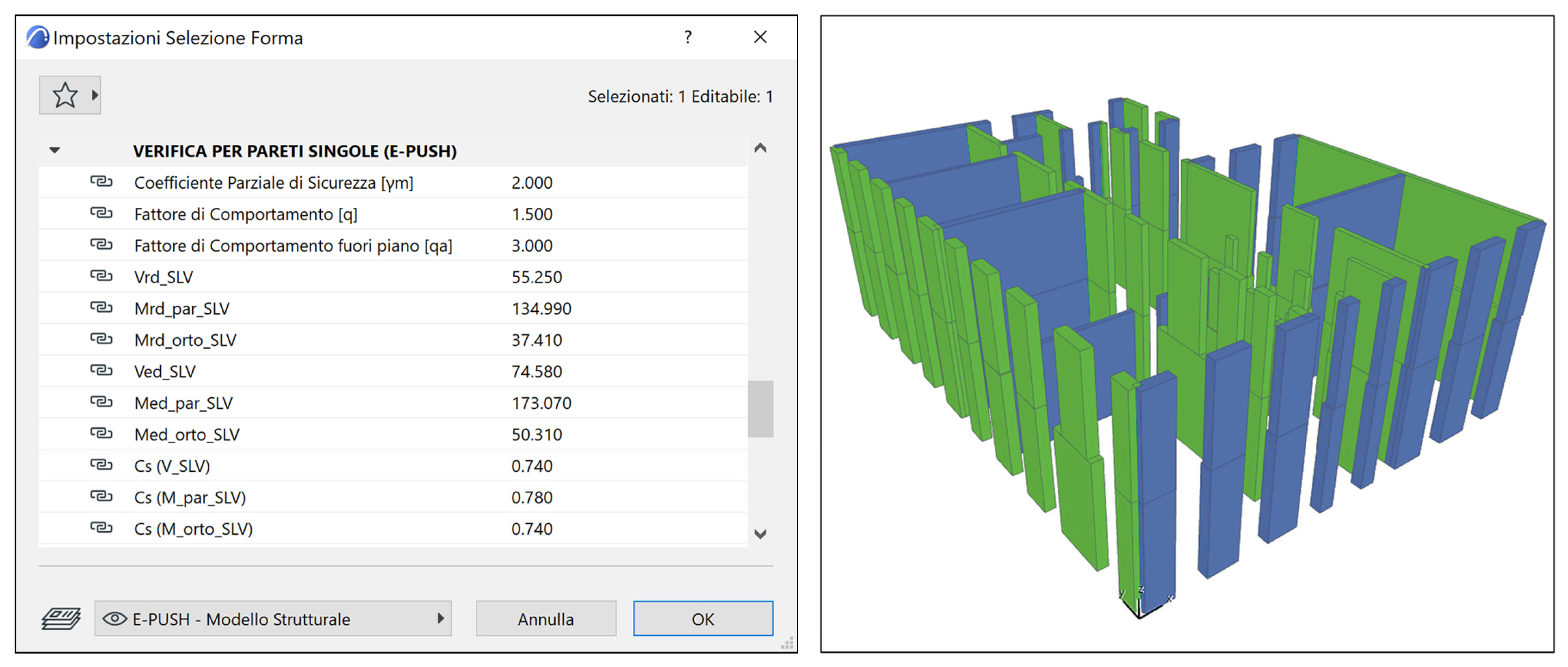
Afterwards, using other components “C#”, the values of strengths and stresses under horizontal actions for diagonal shear, in-plane and out-of-plane flexural verifications are calculated for each structural wall in accordance with the Italian Building Code [14]. The script output (Figure 9) also provides the values of the safety coefficient for each wall and the consequent seismic risk index for the investigated structure by comparing the seismic demand and the actual capacity.
The outcomes of the analysis are further emphasized in a 3D graphic representation, where wall elements are plotted in different colors depending on the safety coefficient of the element itself, so facilitating the identification of critical elements. The outcomes of the analysis for the ”Bernardo Rucellai” school are summarized again in Figure 9, where elements satisfying the assessment () are represented in green, while the other elements are represented in red if , in orange if and in yellow if .
3.2.4. Seismic Assessment: Non-Linear Static Analysis
Since in the “Bernardo Rucellai” school structure the presence of efficient and resistant in-plane connections between aligned masonry walls has been detected, a seismic non-linear static analysis has been performed, considering sets of connected masonry walls belonging to the same alignment, so accounting for the force redistribution capability of the elements of each alignment, beyond the elastic limit.
The key steps of the original script developed in Grasshopper for the computation of the capacity curves and of the seismic risk index for each wall alignment are briefly discussed below.
At first, by using a specific Archicad feature, the algorithm identifies the walls belonging to a given alignment. The relevant values defining the capacity curves of each wall, namely the elastic stiffness , the shear strength , the elastic displacement and the ultimate displacement , are computed by specific C# components as
where , and represent the length, the thickness and the height of the wall, respectively, and represent the elastic modulus and the shear modulus of the masonry, respectively, is the shear strength of the masonry, is a corrective coefficient, depending on the ratio ( [15]), is the value of the compressive stress induced by the seismic combination and is the ductility coefficient.
In an stories building, the algorithm starts from the distribution of seismic forces , acting on the alignment at the -th story. The distribution can be, as usual, proportional to the story elevation and to the quota of the seismic weight of the k-th floor supported by the given alignment, according to the equation
where is the total shear acting at the base of the alignment and the summation is extended to all floors. The capacity curve is evaluated by an iterative procedure using "Anemone" Grasshopper plug-in, as summarized in Figure 10. The iteration starts by considering the last story and then moves to the lower floors for each iteration step.
The total force acting on the alignment is subdivided in a suitable number of increments: for instance, as in the case study, .
At the -th step of the iterative procedure, the algorithm considers a total force acting on the alignment which is given by
The seismic force to be applied to the -th story is thus
Considering an alignment composed by shear walls, at the -th step of the iterative procedure, the total lateral stiffness of the alignment at -th floor results, to a first approximation
where is the lateral stiffness of the -th wall element at the -th level, as determined at the previous -th step, and the sum extended to all the shear walls, which are present at the considered floor and that are extended to the foundation.
The inter-story drift is then
where represents the shear transferred by the upper story.
At each step of the procedure, the inter-story drift is compared with the elastic displacement and with the ultimate displacement of each shear wall, considering three possible situations:
- the wall is still in elastic phase ()
- the wall is in plastic range ()
- the wall is collapsed ()
When the previous checks are completed, it is possible to calculate the corresponding shear transferred by the story and its total lateral stiffness:
Once the analysis of the -th story is concluded it is possible to move to the underlying story, -th, repeating the procedure described before, and so on until the lowest level is reached.
For each step of the iterative procedure, the total displacement, which is the sum of the inter-story displacements, and the total shear at the base of the alignment are identified. The algorithm is run until a value of the total base shear reduces to a suitable percentage of the maximum base shear: about 80%, according to the Italian code [14]. The capacity curve and the seismic demand are plotted for each alignment in a parametric diagram within the Rhinoceros display environment to evaluate the seismic risk index, , which is the ratio between the shear strength and the shear demand
The capacity curves and the seismic demands of the six relevant alignments of the “Bernardo Rucellai” school, so derived, are shown in Figure 11.
It should be remarked that in Figure 11, single walls not belonging to alignments are not reported since they have been previously considered in the linear static analysis. In fact, dealing with flexible floor hypothesis, they do not participate in force redistribution. It must be stressed that the minimum seismic risk index for the alignments is (alignment no. 4 in Figure 11).
Considering that the minimum seismic risk index for the single walls is , the seismic risk index of the building in the present condition is , and therefore strengthening interventions are necessary.
Of course, when, as in the case study, buildings are characterized by flooring systems that are flexible in their plane, the analysis should stop at this stage. Anyhow, in order to illustrate all the relevant features of the proposed procedure, a 3D global analysis of the building has also been carried out. This 3D analysis allows the evaluation of the effectiveness of a strengthening intervention, consisting of the introduction of steel bracing diaphragms or reinforced concrete slabs at the floor level, which is often proposed for its simplicity. The intervention increases the rigidity of the floors in such a way that a “box” behavior of the building can be hypothesized under seismic actions and the plastic redistribution capacity of the structure can be fully exploited.
The resulting global capacity curves and verifications on the ADRS plane, obtained by means of the E-PUSH software for the so-strengthened structure, are shown in Figure 12.
3.3. Analysis Model: Collection of Analysis Results in Archicad
When all analyses are performed, data gathered from the code are collected and returned to Archicad, in a reverse procedure from the initial one, to generate a model, called the "analysis model", composed only of structural masonry walls. The data for each wall refer not only to the information previously specified in the architectural and structural model, but also to that resulting from E-PUSH via the Grasshopper’s algorithm. These include the loads, the stresses and the outcomes of the structural analyses (capacity, demand, safety factors and seismic risk indices). The results of the analyses are finally collected, setting up suitable interactive abacuses.
3.4. Updating of the HBIM Model: Strengthening Interventions
Using the graphic overwriting (Figure 13) it is possible to visualize directly on the model the information related to each analysis that has been performed, so allowing an impressive and intuitive representation of the results, for example, highlighting elements satisfactorily verified or not. The three models obtained, the architectural, structural and analysis models, are layered and positioned on various levels, so enabling individual examination with no interference.
Moreover, the proposed procedure allows a customizable project of strengthening interventions in BIM to be carried out using the “Renovation” feature in Archicad. In this framework, the program allows the relevant state of each element to be specified: existing, to be reinforced, new, and, using the restructuring filters, it is possible to define which elements should be displayed or hidden. In this way, different project statuses of the building, such as current and post-intervention status, can be created and managed in the same BIM model, as illustrated in Figure 14.
In the procedure, this feature is mainly used on the elaborated structural model. The definition of a new user-defined property, called "intervention description", permits the description of the type of retrofitting intervention on a specified wall. Items for which action is expected should be reported and duplicated to represent the post-intervention version of the model.
The update in the informed model of the characteristics of the elements on which interventions are planned can be carried out in two different ways, depending on whether the intervention can be schematized or not in the structural modelling used, according to operations of the E-PUSH method.
For all the interventions that involve the update of one of the input properties of the Grasshopper algorithm, such as geometrical or mechanical characteristics, it is possible to determine the actual improvements by performing the analysis using the VPL code also on the post-intervention version of the structural model. In this way, it is possible to represent on the model all the proposed strengthening interventions that are proposed, such as, for example, increasing the resistant sections of the walls, including the closing of doors and windows, reinforcements and improvement of the quality of the masonry, such as the use of reinforced mortar plaster, insertion of steel reinforcement composed of steel and composite strips, and so on.
In this way, the post-intervention mechanical properties of the walls can be considered, evaluating the corresponding seismic risk index, , depending on the strengthening interventions. Consequently, a powerful and flexible management environment is set up, able not only to assess the effects of the interventions but also to identify the most effective and suitable ones.
4. Discussion
The implementation of structural analysis procedures in a BIM environment can facilitate the assessment process of historical masonry buildings. In fact, as illustrated in the previous sections, all the relevant information for the definition of the structural model can be directly derived from the HBIM model, and structural analysis and verifications can be performed by algorithm modelling without the use of third-party software.
The proposed approach relies on a computational method for linear and non-linear static analysis of masonry structures, previously developed by the authors [6,7], and now implemented in connection with the BIM model via Grasshopper. The analysis method requires the definition of a very simple structural model with a limited number of input data, which can be easily extracted by the BIM model, speeding up the process of the assessment and reducing errors in comparison with traditional procedures based on CAD programs. By adopting this methodology, information is managed and updated throughout the process, making the work easily editable and shareable. This allows you to acquire an updated model in real time during the design process, preventing redundancies or loss of information that could affect both economic and temporal terms.
In fact, one of the main advantages is the ability to modify the digital model and directly update the results of the assessment, avoiding a total remodeling of the project and preserving all the information in a single environment.
The procedure enables a thorough definition of the information relating to the building under consideration, rapid modification of the input data and rapid production of accurate and consistent analytical results at any stage of the design, and documents of all types, such as abacuses of measurements and metric calculations, are all within the same model. Its implementation on the case study already described in Section 3, demonstrates that the proposed approach, based on the E-PUSH program, can be successfully adopted for the assessment of existing masonry structures and the design of strengthening interventions, providing safety coefficients and seismic risk indexes coincident with those obtained following the traditional workflow. The main advantage is a drastic simplification of the assessment process and, consequently, a more efficient choice of the strengthening interventions, which can be easily compared inside the BIM environment. It must be underlined that, in any case, the results are consistent with those obtained with other software packages.
5. Conclusions
The safety assessment of existing masonry structures is an extremely relevant topic, especially for those countries with a built heritage characterized by a significant seismic vulnerability. Therefore, the definition of a reliable and suitable assessment procedure is a key aspect of the preservation of historical buildings, as is also providing a definition of the most appropriate and respectful strengthening interventions, if necessary.
In this study, a parametric procedure in the BIM environment for the assessment of existing masonry buildings is presented, combining the potential of the E-PUSH algorithm with the advantages of Heritage Building Information Modeling, which allows enhanced interoperability between BIM software and algorithmic modeling programs.
The algorithmic modeling applied to BIM translates into the possibility for the designer to program codes autonomously, in such a way that repetitive or particularly complex actions required to define the digital model can be carried out “automatically”, facilitating the assessment process, reducing errors and redundancies, or loss of information, and optimizing the time. The development of advanced codes can, for example, enable structural analyses to be carried out on the Building Information Model to assess the vulnerability of existing masonry buildings.
The advantages of using algorithmic modeling software integrate well with the characteristics of Heritage Building Information Modeling. The informed model thus becomes an essential part of the process of the evaluation and management of historical heritage, providing for every building the crucial reference for understanding and monitoring documentation and a continuously updated source of data suitable for assisting the stakeholders in conservation, restoration and reconstruction projects.
The satisfactory application of the proposed procedure to a relevant case study, the “Bernardo Rucellai” school in Florence, confirms its potentialities and encourages further developments.
Supplementary Materials
The software E-PUSH is available online at https://www.researchgate.net/project/E-PUSH and is distributed under a Creative Commons Attribution.
Author Contributions
Conceptualization, P.C., F.L., B.P., M.M. and A.M.; methodology, P.C., F.L., B.P., M.M. and A.M.; software, P.C., F.L., B.P., M.M. and A.M.; validation, P.C., F.L., B.P., M.M. and A.M.; resources, P.C.; writing—original draft preparation, P.C., F.L., B.P., M.M. and A.M.; writing—review and editing, P.C., F.L., B.P., M.M. and A.M.; funding acquisition, P.C. All authors have read and agreed to the published version of the manuscript.
Funding
This research received no external funding.
Institutional Review Board Statement
Not applicable.
Informed Consent Statement
Not applicable.
Data Availability Statement
The data presented in this study are available on request from the corresponding authors. The data are not publicly available as they cannot be used for commercial purposes.
Conflicts of Interest
The authors declare no conflict of interest.
References
- International Council on Monuments and Sites (ICOMOS). International Charter for the Conservation and Restoration of Monuments and Sites (The Venice Charter 1964); ICOMOS: Charenton-le-Pont, France, 1965; Available online: https://www.icomos.org/charters/venice_e.pdf (accessed on 10 January 2022).
- International Council on Monuments and Sites (ICOMOS). Charter—Principles for the Analysis, Conservation and Structural Restoration of Architectural Heritage, the ICOMOS 14th General Assembly in Victoria Falls, Zimbabwe, in 2003; ICOMOS: Charenton-le-Pont, France, 2003; Available online: https://www.icomos.org/charters/structures_e.pdf (accessed on 10 January 2022).
- ICOMOS International Scientific Committee for Analysis and Restoration of Structures of Architectural Heritage (I.S.C.A.R.S.H.A.) Recommendations for the Analysis, Conservation and Structural Restoration of Architectural Heritage; ICOMOS: Charenton-le-Pont, France, 2003; Available online: http://orcp.hustoj.com/wp-content/uploads/2016/04/Recommendations-ICOMOS.pdf (accessed on 10 January 2022).
- International Council on Monuments and Sites (ICOMOS). Monuments and Sites I—International Charters for Conservation and Restoration, 2nd ed.; Petzet, M., Ed.; ICOMOS: Charenton-le-Pont, France, 2004; Available online: http://openarchive.icomos.org/id/eprint/431/1/Monuments_and_Sites_1_Charters.pdf (accessed on 10 January 2022).
- Croce, P. New Frontiers of Composites Applications in Heritage Buildings: Repair of Exposed Masonry of St. Nicola Church in Pisa. J. Compos. Sci. 2021, 5, 218. [Google Scholar] [CrossRef]
- Croce, P.; Landi, F.; Formichi, P. Probabilistic Seismic Assessment of Existing Masonry Buildings. Buildings 2019, 9, 237. [Google Scholar] [CrossRef] [Green Version]
- Beconcini, M.L.; Cioni, P.; Croce, P.; Formichi, P.; Landi, F.; Mochi, C. Non-linear static analysis of masonry buildings under seismic actions. In Proceedings of the IMSCI 2018—12th International Multi-Conference on Society, Cybernetics and Informatics, Orlando, FL, USA, 8–11 July 2018; pp. 126–131, ISBN 978-194176385-8. Available online: http://www.iiisci.org/Journal/CV$/sci/pdfs/EA239AY18.pdf (accessed on 10 January 2022).
- Croce, P.; Beconcini, M.L.; Formichi, P.; Cioni, P.; Landi, F.; Mochi, C.; Giuri, R. Influence of mechanical parameters on non-linear static analysis of masonry buildings: A relevant case-study. Procedia Struct. Integr. 2018, 11, 331–338. [Google Scholar] [CrossRef]
- Croce, P.; Landi, F.; Formichi, P.; Beconcini, M.L.; Puccini, B.; Zotti, V. Non-linear methods for the assessment of seismic vulnerability of masonry historical buildings. In Proceedings of the 4th International Conference on Protection of Historical Constructions, Athens, Greece, 25–27 October 2021; Vaias, I., Mazzolani, F.M., Eds.; Springer Nature Switzerland: Cham, Switzerland, 2021; pp. 651–670. [Google Scholar] [CrossRef]
- Croce, P.; Landi, F.; Martino, M.; Puccini, B. An integrated BIM methodology for the seismic assessment of masonry buildings. In Proceedings of the IABSE Symposium, Wroclaw 2020: Sinergy of Culture and Civil Engineering-History and Challenges, Wroclaw, Poland, 20–22 May 2020; IABSE: Zurich, Switzerland, 2020; pp. 967–974, ISBN 978-385748169-7. [Google Scholar]
- Croce, P.; Landi, F.; Martino, M.; Puccini, B.; Maneo, A. Parametric Approach in BIM Environment for the Assessment of Ex-isting Masonry Buildings. In Proceedings of the IABSE Congress Ghent 2021: Structural Engineering for Future Societal Needs, Ghent, Belgium, 22–24 September 2021; IABSE: Zurich, Switzerland, 2021. [Google Scholar]
- EN1998-3; Eurocode 8: Design of Structures for Earthquake Resistance—Part 3: Assessment and Retrofitting of Buildings. CEN: Brussels, Belgium, 2005.
- International Organization for Standardization (ISO). ISO 13822 Bases for Design of Structures—Assessment of Existing Structures; ISO: Geneva, Switzerland, 2010. [Google Scholar]
- Italian Ministry of Infrastructure and Transport. NTC 2018-Italian Building Code; Istituto Poligrafico e Zecca dello Stato: Rome, Italy, 2018. (In Italian) [Google Scholar]
- Italian Public Works Council. Guidelines for Application of Italian Building Code; Istituto Poligrafico e Zecca dello Stato: Rome, Italy, 2019. (In Italian) [Google Scholar]
- Italian Public Works Council. Guidelines for the Evaluation and Reduction of Seismic Risk of Cultural Heritage with Reference to the Italian Building Code; Istituto Poligrafico e Zecca dello Stato: Rome, Italy, 2006. (In Italian) [Google Scholar]
- Giresini, L.; Taddei, F.; Solarino, F.; Mueller, G.; Croce, P. Influence of Stiffness and Damping Parameters of Passive Seismic Control Devices in One-Sided Rocking of Masonry Walls. J. Struct. Eng. 2022, 148, 04021257. [Google Scholar] [CrossRef]
- Giresini, L.; Croce, P. Reduction of Housner’s Coefficient of Restitution for Masonry Walls under One-Sided Rocking. In Proceedings of the 8th Int. Conf. on Computational Methods in Structural Dynamics and Earthquake Engineering, COMPDYN 2021, Athens, Greece, 28–30 June 2021; National Technical University: Athens, Greece, 2021; Volume 1, pp. 702–715. [Google Scholar]
- Solarino, F.; Giresini, L.; Croce, P. Influence of the Elasto-Plastic Behavior of Tie-Rods in the Response of Rocking Masonry Walls through Seismic Demand Hazard Curves. In Proceedings of the 8th Int. Conf. on Computational Methods in Structural Dynamics and Earthquake Eng, COMPDYN 2021, Athens, Greece, 28–30 June 2021; National Technical University: Athens, Greece, 2021; Volume 1, pp. 664–681. [Google Scholar]
- Marques, R.; Lourenco, P. Possibilities and comparison of structural component models for the seismic assessment of modern unreinforced masonry buildings. Comput. Struct. 2011, 89, 2079–2091. [Google Scholar] [CrossRef] [Green Version]
- Tomažević, M. Improvement of Computer Program POR; ZRMK-IK Report; Building and Civil Engineering Institute: Ljubljana, Slovenia, 1978. (In Slovene) [Google Scholar]
- Turnšek, V.; Ĉaĉoviĉ, F. Some experimental results on the strength of brick masonry walls. In Proceedings of the 2nd Intern. Brick Masonry Conference, Stoke-on-Trent, UK, 12–15 April 1970; British Ceramic Research Association: Stoke-on-Trent, UK, 1971; pp. 149–156. [Google Scholar]
- Fajfar, P. A Nonlinear Analysis Method for Performance-Based Seismic Design. Earthq. Spectra 2000, 16, 573–592. [Google Scholar] [CrossRef]
- MathWorks Matlab. Available online: https://it.mathworks.com/products/matlab.html (accessed on 10 January 2022).
- López, F.J.; Lerones, P.M.; Llamas, J.; Gómez-García-Bermejo, J.; Zalama, E. A review of heritage building information modeling (H-BIM). Multimodal Technol. Interact. 2018, 2, 21. [Google Scholar] [CrossRef] [Green Version]
- Volk, R.; Stengel, J.; Schultmann, F. Building Information Modeling (BIM) for existing buildings—Literature review and future needs. Autom. Constr. 2014, 38, 109–127. [Google Scholar] [CrossRef] [Green Version]
- Khaddaj, M.; Srour, I. Using BIM to Retrofit Existing Buildings. Procedia Eng. 2016, 145, 1526–1533. [Google Scholar] [CrossRef] [Green Version]
- Kamaruzaman, N.U.S.N. Historic Building Information Modelling (Hbim): A Review. In Carving the Future Built Environment: Environmental, Economic and Social Resilience; Wahid, P.A.J., Aziz Abdul Samad, P.I.D.A., Sheikh Ahmad, P.D.S., Pujinda, A.P.D.P., Eds.; Future Academy: Nicosia, Cyprus, 2020; Volume 2, pp. 587–594. [Google Scholar] [CrossRef]
- Jordan-Palomar, I.; Tzortzopoulos, P.; García-Valldecabres, J.; Pellicer, E. Protocol to Manage Heritage-Building Interventions Using Heritage Building Information Modelling (HBIM). Sustainability 2018, 10, 908. [Google Scholar] [CrossRef] [Green Version]
- Moyano, J.; Gil-Arizón, I.; Nieto-Julián, J.E.; Marín-García, D. Analysis and management of structural deformations through parametric models and HBIM workflow in architectural heritage. J. Build. Eng. 2021, 45, 103274. [Google Scholar] [CrossRef]
- International Organization for Standardization (ISO). ISO 12491 Information and Documentation—A Reference Ontology for the Interchange of Cultural Heritage Information; ISO: Geneva, Switzerland, 2014. [Google Scholar]
- Murphy, M.; McGovern, E.; Pavia, S. Historic building information modelling (HBIM). Struct. Surv. 2009, 27, 311–327. [Google Scholar] [CrossRef] [Green Version]
- Sacks, R.; Eastman, C.; Lee, G.; Teicholz, P. BIM Handbook: A Guide to Building Information Modeling for Owners, Designers, Engineers, Contractors, and Facility Managers, 3rd ed.; John Wiley & Sons, Inc.: Hoboken, NJ, USA, 2018. [Google Scholar] [CrossRef]
- Wong, J.; Yang, J. Research and Application of Building Information Modelling (BIM) in the Architecture, Engineering and Construction (AEC) Industry: A Review and Direction for Future Research. In Proceedings of the 6th International Conference on Innovation in Architecture, Engineering & Construction (AEC), University Park, PA, USA, 9–11 June 2010; Loughborough University: Loughborough, UK, 2010; pp. 356–365. [Google Scholar]
- NBIMS-US V3. National BIM Standard—United States Version 3; National Institute of Building Sciences: Washington, DC, USA, 2015. [Google Scholar]
- Croce, V.; Caroti, G.; De Luca, L.; Jacquot, K.; Piemonte, A.; Véron, P. From the Semantic Point Cloud to Heritage-Building Information Modeling: A Semiautomatic Approach Exploiting Machine Learning. Remote Sens. 2021, 13, 461. [Google Scholar] [CrossRef]
- Di Stefano, F.; Gorreja, A.; Malinverni, E.S.; Mariotti, C. Knowledge modeling for heritage conservation process: From survey to hbim implementation. ISPRS Int. Arch. Photogramm. Remote Sens. Spat. Inf. Sci. 2020, XLIV-4, 19–26. [Google Scholar] [CrossRef]
- Scianna, A.; Gaglio, G.F.; La Guardia, M. Acquisition and management of historical buildings data: From survey to the con-struction of the HBIM model. Boll. SIFET Sez. Sci. 2019, 4, 1–9. (In Italian) [Google Scholar]
- Pelliccio, A.; Grande, E.; Saccucci, M. HT_BIM: Parametric modelling for the assessment of risk in historic centers. Disegnarecon 2017, 18, 10. [Google Scholar]
- Bienvenido-Huertas, D.; Nieto-Julián, J.E.; Moyano, J.J.; Macías-Bernal, J.M.; Castro, J. Implementing Artificial Intelligence in H-BIM Using the J48 Algorithm to Manage Historic Buildings. Int. J. Arch. Herit. 2019, 14, 1148–1160. [Google Scholar] [CrossRef]
- Domaneschi, M.; Villa, V.; Cimellaro, G.P.; Caldera, C.; Noori, A.Z.; Marasco, S.; Ansari, F. Integrating Bim with On Site Investigation for Seismic Vulnerability Assessment. In Proceedings of the 7th ECCOMAS Thematic Conference on Computational Methods in Structural Dynamics and Earthquake Engineering, COMPDYN 2019, Crete, Greece, 24–26 June 2019; National Technical University: Athens, Greece, 2019; pp. 544–553. [Google Scholar] [CrossRef] [Green Version]
- Mondello, A.; Garozzo, R.; Salemi, A.; Santagati, C. Hbim for the seismic vulnerability assessment of traditional bell towers. ISPRS Int. Arch. Photogramm. Remote Sens. Spat. Inf. Sci. 2019, XLII-2/W15, 791–798. [Google Scholar] [CrossRef] [Green Version]
- Argiolas, R.; Cazzani, A.; Reccia, E.; Bagnolo, V. From lidar data towards hbim for structural evaluation. ISPRS Int. Arch. Photogramm. Remote Sens. Spat. Inf. Sci. 2019, XLII-2/W15, 125–132. [Google Scholar] [CrossRef] [Green Version]
- AUTODESK AutoCAD 2020. Available online: https://www.autodesk.it/products/autocad/ (accessed on 10 January 2022).
- Jouan, P.; Hallot, P. Digital Twin: Research Framework to Support Preventive Conservation Policies. ISPRS Int. J. Geo Inf. 2020, 9, 228. [Google Scholar] [CrossRef] [Green Version]
- Bagnolo, V.; Argiolas, R.; Cuccu, A. Hbim for archaeological sites: From sfm based survey to algorithmic modeling. ISPRS Int. Arch. Photogramm. Remote Sens. Spat. Inf. Sci. 2019, XLII-2/W9, 57–63. [Google Scholar] [CrossRef] [Green Version]
- Bagnolo, V.; Argiolas, R.; Cuccu, A. Digital survey and algorithmic modeling in hbim. Towards a library of complex construction elements. ISPRS Int. Arch. Photogramm. Remote Sens. Spat. Inf. Sci. 2019, XLII-4/W12, 25–31. [Google Scholar] [CrossRef] [Green Version]
- Andriasyan, M.; Moyano, J.; Nieto-Julián, J.E.; Antón, D. From Point Cloud Data to Building Information Modelling: An Automatic Parametric Workflow for Heritage. Remote Sens. 2020, 12, 1094. [Google Scholar] [CrossRef] [Green Version]
- Graphisoft Archicad 2019. Available online: https://www.graphisoft.com/Archicad/ (accessed on 10 January 2022).
- McNeel Europe Grasshopper—Algorithmic Modeling for Rhino. Available online: https://www.grasshopper3d.com/ (accessed on 28 January 2020).
- Rhinoceros [Computer Software] 2021. Available online: https://www.rhino3d.com (accessed on 8 December 2021).
- Croce, P.; Beconcini, M.L.; Formichi, P.; Landi, F.; Puccini, B.; Zotti, V. Bayesian Methodology for Probabilistic Description of Mechanical Parameters of Masonry Walls. ASCE-ASME J. Risk Uncertain. Eng. Syst. Part A Civ. Eng. 2021, 7, 04021008. [Google Scholar] [CrossRef]
- Croce, P.; Beconcini, M.L.; Formichi, P.; Cioni, P.; Landi, F.; Mochi, C.; De Lellis, F.; Mariotti, E.; Serra, I. Shear modulus of masonry walls: A critical review. Procedia Struct. Integr. 2018, 11, 339–346. [Google Scholar] [CrossRef]
- Beconcini, M.L.; Croce, P.; Formichi, P.; Landi, F.; Puccini, B. Experimental Evaluation of Shear Behavior of Stone Masonry Wall. Materials 2021, 14, 2313. [Google Scholar] [CrossRef]
- Croce, P.; Marsili, F.; Klawonn, F.; Formichi, P.; Landi, F. Evaluation of statistical parameters of concrete strength from secondary experimental test data. Constr. Build. Mater. 2018, 163, 343–359. [Google Scholar] [CrossRef]
- Croce, P.; Landi, F.; Formichi, P.; Beconcini, M.L.; Puccini, B.; Zotti, V. In Situ Tests Procedures for the Evaluation of Masonry Mechanical Parameters. In Proceedings of the 4th International Conference on Protection of Historical Constructions, Athens, Greece, 25–27 October 2021; Vaias, I., Mazzolani, F.M., Eds.; Springer Nature Switzerland: Cham, Switzerland, 2021; pp. 20–33. [Google Scholar]
- EN1996-1-1; Eurocode 6: Design of Masonry Structures—Part 1-1: General Rules for Reinforced and Unreinforced Masonry Structures. CEN: Brussels, Belgium, 2005.
Figure 1.
Flowchart illustrating the assessment procedure of heritage structures (adapted from [5]).
Figure 1.
Flowchart illustrating the assessment procedure of heritage structures (adapted from [5]).

Figure 2.
Proposed BIM workflow: procedure for the structural evaluation of existing masonry building.
Figure 2.
Proposed BIM workflow: procedure for the structural evaluation of existing masonry building.

Figure 3.
“Bernardo Rucellai” school: (a) a fish-eye photo of the façade; (b) Building Information Model of the school.
Figure 3.
“Bernardo Rucellai” school: (a) a fish-eye photo of the façade; (b) Building Information Model of the school.

Figure 4.
Informed Architectural Model of the Building in Archicad.

Figure 5.
Double flat jack test carried out on a stone wall of the “Bernardo Rucellai” school: (a) test arrangement, (b) measurement of displacements, (c) experimental stress–strain diagram in blue and tri-linear approximation in orange.
Figure 5.
Double flat jack test carried out on a stone wall of the “Bernardo Rucellai” school: (a) test arrangement, (b) measurement of displacements, (c) experimental stress–strain diagram in blue and tri-linear approximation in orange.


Figure 6.
Loading phase in the informed structural model of the building in Archicad.

Figure 7.
Code developed in Grasshopper to perform static verifications, linear and non-linear static analysis of an existing masonry structure.
Figure 7.
Code developed in Grasshopper to perform static verifications, linear and non-linear static analysis of an existing masonry structure.

Figure 8.
Load analysis and calculation of stresses, as the sum of (a) self-weight, (b) the weight of masonry spandrels, (c) the loads from floors and (d) the loads from the overlying walls.
Figure 8.
Load analysis and calculation of stresses, as the sum of (a) self-weight, (b) the weight of masonry spandrels, (c) the loads from floors and (d) the loads from the overlying walls.

Figure 9.
Code developed in Grasshopper to perform linear static analysis of an existing masonry structure and 3D representation of the results.
Figure 9.
Code developed in Grasshopper to perform linear static analysis of an existing masonry structure and 3D representation of the results.

Figure 10.
Code developed in Grasshopper to perform non-linear static analysis for alignments of an existing masonry structure.
Figure 10.
Code developed in Grasshopper to perform non-linear static analysis for alignments of an existing masonry structure.

Figure 11.
Capacity curve and seismic demand plotted for each alignment of the “Bernardo Rucellai” school in Rhinoceros.
Figure 11.
Capacity curve and seismic demand plotted for each alignment of the “Bernardo Rucellai” school in Rhinoceros.

Figure 12.
Final output of the global pushover analysis of the building in the case of strengthening intervention, consisting of the introduction of horizontal steel bracing systems at the floor level, aiming to achieve a box behavior. Verification in the acceleration-displacement response spectra (ADRS) plane: (a) x-direction, , (b) y-direction, .

Figure 13.
Analysis Model: collection of analysis results for the considered case study in Archicad.
Figure 13.
Analysis Model: collection of analysis results for the considered case study in Archicad.

Figure 14.
Strengthening interventions on the structural model of the “Bernardo Rucellai” school in Archicad: (a) current and (b) post-intervention status.
Figure 14.
Strengthening interventions on the structural model of the “Bernardo Rucellai” school in Archicad: (a) current and (b) post-intervention status.


Table 1.
Traditional workflow and proposed BIM workflow: procedure for the structural evaluation of existing masonry building.
Table 1.
Traditional workflow and proposed BIM workflow: procedure for the structural evaluation of existing masonry building.
| Traditional Workflow | Proposed BIM Workflow | |
|---|---|---|
| Historical analysis | Collection of historical documentation of the building. | Architectural Model in Archicad collection of historical documentation of the building.  |
| Cognitive analysis | In situ survey and photo campaign. Development of the 3D representation of the building in a suitable CAD program, such as AutoCAD.  | Architectural Model in Archicad Development of a suitable BIM model using traditional and advanced survey techniques of relevant information in BIM.  |
| Mechanical characterization of materials | Investigation and tests in situ or in laboratory. Identification of the structural elements and materials from CAD drawings.  | Structural Model in Archicad: collection of structural parameters.  |
| Structural analysis | Definition of the 3D structural model. Load analysis and data table on Excel. Linear and non-linear static analysis on E-PUSH.  | Structural analysis in Grasshopper and analysis results in Archicad. Load analysis, vertical loads analysis, linear and a non-linear static analysis. |
| Proposal of strengthening interventions | Post-intervention status of the building. Updating of the data table and new analysis on E-PUSH.  | Post-intervention status of the building. Updating of the model in Archicad and new analysis in Grasshopper via E-PUSH.  |
Publisher’s Note: MDPI stays neutral with regard to jurisdictional claims in published maps and institutional affiliations. |
© 2022 by the authors. Licensee MDPI, Basel, Switzerland. This article is an open access article distributed under the terms and conditions of the Creative Commons Attribution (CC BY) license (https://creativecommons.org/licenses/by/4.0/).
Share and Cite
MDPI and ACS Style
Croce, P.; Landi, F.; Puccini, B.; Martino, M.; Maneo, A. Parametric HBIM Procedure for the Structural Evaluation of Heritage Masonry Buildings. Buildings 2022, 12, 194. https://0-doi-org.brum.beds.ac.uk/10.3390/buildings12020194
AMA Style
Croce P, Landi F, Puccini B, Martino M, Maneo A. Parametric HBIM Procedure for the Structural Evaluation of Heritage Masonry Buildings. Buildings. 2022; 12(2):194. https://0-doi-org.brum.beds.ac.uk/10.3390/buildings12020194
Chicago/Turabian StyleCroce, Pietro, Filippo Landi, Benedetta Puccini, Massimiliano Martino, and Alessio Maneo. 2022. "Parametric HBIM Procedure for the Structural Evaluation of Heritage Masonry Buildings" Buildings 12, no. 2: 194. https://0-doi-org.brum.beds.ac.uk/10.3390/buildings12020194
Note that from the first issue of 2016, this journal uses article numbers instead of page numbers. See further details here.