
3D Printing Devices and Reinforcing Techniques for Extruded Cement-Based Materials: A Review


1
Key Laboratory for Resilient Infrastructures of Coastal Cities (MOE), College of Civil and Transportation Engineering, Shenzhen University, Shenzhen 518061, China
2
Institute of Applied Physics and Materials Engineering, University of Macau, Macau SAR 999078, China
*
Author to whom correspondence should be addressed.
Buildings 2022, 12(4), 453; https://0-doi-org.brum.beds.ac.uk/10.3390/buildings12040453
Submission received: 27 February 2022
/
Revised: 30 March 2022
/
Accepted: 1 April 2022
/
Published: 7 April 2022
(This article belongs to the Special Issue Additive Manufacturing of Construction and Building Materials)
Abstract
:The three-dimensional (3D) printing technique for cement-based materials has been actively investigated and utilized in civil engineering. However, there is no systematic review of the fabricating devices. This paper reviews the software and hardware for extrusion-based 3D concrete printing. Firstly, a dedicated tool path generating software is urgently needed to meet the cementitious printing applications and to improve printing quality with toolpath optimizations. Secondly, the existing printing equipment was summarized and discussed, concluding the pros and cons of various 3D motion systems, material systems, and nozzle units. Suitable choices for scientific research and engineering applications were recommended. The reinforcing techniques were categorized and concluded with the existing drawbacks and the research trend. A hybrid manufacturing system of 3D printing and the reinforcing technique was then proposed with a system diagram and flowchart.
1. Introduction
Three-Dimensional Printing Technology (3DPT) has been widely studied, commercialized, and applied in different domains. Printable cementitious composites have attracted attention in the construction domain with many structural engineering components fabricated [1] and even the concept of a space base station on the moon [2]. 3DPT on cementitious material has a bright future for green building, environmental protection, and energy-saving [3,4,5,6].
Concrete printing differs from polymer printing, which only has a physical change during the printing process from the nozzle to the printing bed, e.g., liquid-form plastic to solid, melt- or powder- state metal to solid metal. However, the cementitious materials have both physical and chemical changes from liquid paste inner the nozzle to the printing bed still in a paste status, hydrating to solid form.
The existing 3D Concrete Printing (3DCP) Techniques (3DCPT) mostly utilize mortar extrusion, namely 3D Extruding Concrete Printing (3DECP). It needs to pre-mix the materials and feed the mixture into the extruder. Extrudable material needs to meet the properties of printability, pump-ability, buildability, and open time [7]. According to the references, most printable materials are OPC-based, fewer are geopolymer-based, and some are sulfur and magnesium cement. Admixtures, such as thickener [8], plasticizer [9], and thixotropic agents [10], have been introduced to balance viscosity [11], thixotropy [10], rheology [12], slumping [13], and fluidity [14]. Thus, many printable cementitious materials are available for 3DCP.
The 3DPT is a comprehensive technology of materials and electromechanics. Mechanical techniques can solve the problems of materials. Since large reinforcement can jam and block the extruding mechanism [15], many reinforcing techniques have been investigated, such as inserting rebars, nails, or embedding wires, which have achieved significant mechanical enhancement.
Therefore, printing equipment and reinforcing techniques deserve more research attention. Additionally, there are a lack of reviews concerning printing devices and relevant techniques. A summary of the current printing equipment needs to be carried out to guide the improvement in techniques and relevant research. In this paper, the printing systems were summarized and discussed regarding the toolpath generating software (Section 2.1), motion system (Section 3), material system (Section 4), nozzle unit (Section 5), and reinforcing techniques (Section 6), providing a solid fundamental to the studies on printing devices and techniques.
2. Printing System
One thorough 3D printing procedure starts from the software to the hardware, from the concept model with an origin file via CAD software. Then, the designed sketch is processed into printing commands by a Toolpath Generator (TG). The mixed cement mortar is transmitted to the printing bed to form a 3D object via pumping, squeezing, pushing, or extruding techniques. Finally, the 3D printer fabricates the designated output from the digital tool path and mixed material. As shown in Figure 1, a typical printing process involves three main parts: software, hardware, and material. The concept model can be eventually fabricated via digital, mechanical, and material flows. The 3D printer hardware can be divided into four parts: the control unit, motion system, material system, and the nozzle unit, with discussions in the following sections.
2.1. Printing Software
In addition to the CAD sketching software, the TG typically processes the 3D sketch file in *.stl format and generates printing instructions/commands. The nozzle tip follows the commands to print from one dimension to the final three-dimensional object. The description protocol of the printing commands is usually G-code. More possibilities for printing one given material mix and one printing equipment can be achieved by varying the tool path, the extruding speed, or nozzle moving speed.
Helpful printing strategies can be employed for better printing results by software optimizations based on one printable material and its printing device. Li and Wang [16] carefully designed the printing paths to spiral-spread the embedded cables and increase the compressive strength by 50%. A convex geometry with a fine printing surface and intensity can be achieved by a variable-layer-thickness strategy, as in Figure 2. These technologies are also applicable to 3DCPT.
Therefore, the toolpath optimization is worth studying to achieve better results with the same printable material and printing equipment.
Evidence shows that over half of researchers conduct their concrete printing using TG software [17,18] from the plastic printing technique, Fused Deposition Modeling (FDM). FDM has been well-developed in recent years and many open-source projects are available as a reference to the 3DCP, such as RepRap, Ultimaker, or Repetier. These FDM TGs can still work in 3DCP, e.g., sli3r.exe, curaEngine.exe, and Simplify3d.exe. They have parameters for plastic extrusion but are still compatible with cementitious material.
However, there is one main difference between FDM and 3DCP. The cementitious material has a chemical reacting process from the paste to hardened, while the extruded plastic in FDM is only a physical change from liquid to solid-state. Therefore, the existing printing mechanisms for 3DCP are different from those for FDM. The configurations for a thin, round plastic filament in FDM are melt temperature, feeding filament diameter, infilling density, and layer thickness. The plastic raw material is melted into liquid form, extruded out of the nozzle tip by the feeding pressure, and hardens rapidly as it cools down [19]. However, the cement paste is mixed at room temperature, fed into an open material bin, extruded out of the nozzle tip onto the platform, remaining in a paste state, and hardened to solid. Additionally, typically, the 3DCP printer is larger than a desktop FDM printer.
Some 3DECP parameters are not considered in these FDM slicers, such as material slump, setting time, and rheology. A dedicated TG for 3DCPT is urgently needed.
2.2. Printing Hardware
In addition to the control unit, typical 3D printing hardware involves motion and material systems. The material system includes a material feeder and a printing nozzle. The nozzle extrudes the material quantitively to manufacture a 3D object additively. The motion system carries the nozzle moving in the three-dimension space to fulfill the “3D” printing. Both are given in later sections.
3. Motion System
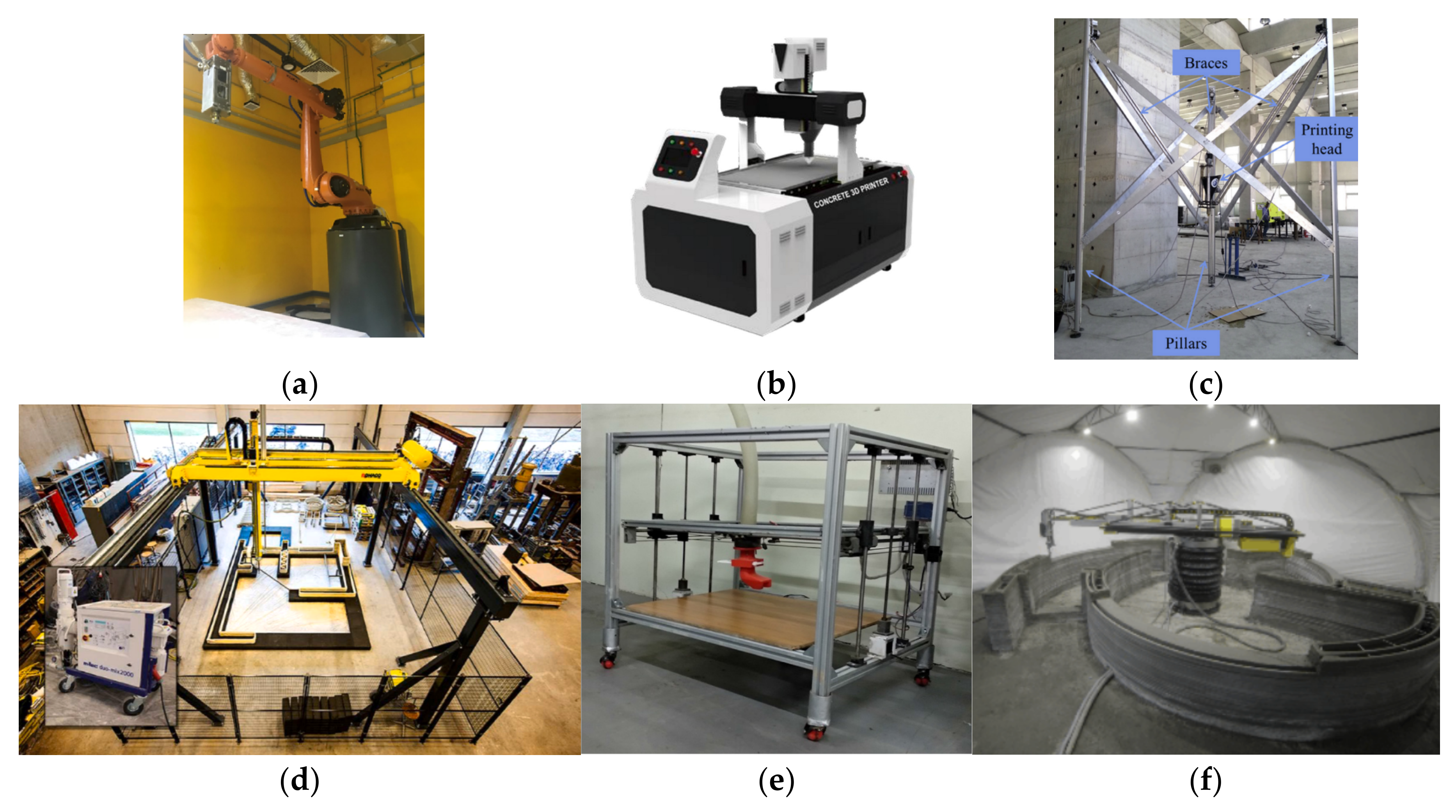
The 3DCP needs an automatic motion system to carry the nozzle unit. Typically, the motion system has three axes x, y, and z, and the printing nozzle is the E axis for extruding. Some other printers have more than three axes to fulfill more possibilities of printing applications, e.g., a 6-axis industrial robot with a new printing route strategy [20], dual nozzles [21], or two robot arms co-working to printing concrete [22]. Several 3D motion systems for 3D printing techniques are widely used in CNC and other industrial domains. The literature motion systems used in 3DCPT can be categorized as Gantry, Frame, Robot-arm, Polar, and Delta types, as in Table 1 and Figure 3, and the typical printers in Figure 4.

Table 1.
Existing motion systems for 3DCPT.
| Name | Illustration * | Pros and Cons | Literatures ** |
|---|---|---|---|
| Gantry |  | Easy assemble, Easy use, Easy maintenance, Uniform resolution, Low cost, Hard to extend the build volume. | [18,23,24,25,26] |
| Frame |  | [8,27,28,29,30,31,32] | |
| Robot Arm |  | Complex assemble, Complex maintenance, Uneven resolution, High cost, Easy to extend the build volume. | [20,33,34,35,36,37,38,39,40,41,42,43,44] |
| Polar |  | Uneven resolution, Mean assemble, Mean use, Mean maintenance, Mean cost, Easy to extend the build volume. | [45,46] |
| Delta |  | Complex assemble, Complex maintenance, Unstable nozzle cartridge, Mean cost, Uneven resolution, Hard to extend the build volume. | [17,47,48,49,50,51,52] |
* The material supplying equipment is excluded; the printing nozzles are in green; and the build volumes are in orange. ** The referred studies have clear evidence (text/s or photo/s) of the motion type.
Gantry (as in Figure 4b,d) and frame (as in Figure 4e) motion systems are commonly used in the FDM technique. They can be easily transplanted for cement printing and extended by enlarging the axis with a consistent positioning resolution for 3DCP, with advantages such as low cost, easy assembly, easy maintenance, and hands-on. Simple mechanical structures, ordinary stepper motors and gears and a simple control board embedded with open-source firmware are sufficient for 3DCP printing research. The build volume cannot be more extensive than the outside of the printer.
Robot arm systems (as in Figure 4a) are the most popular among the five types of motion systems, as concluded in Table 1 and Figure 3. They have a flexible “arm” and nozzle to achieve complex printings, and can easily extend the build volume when mounted on a mobile base [54] or a track. There is a 9 m printer with fabricated structural components, including a usable bridge, at the Hebei University of Technology. The drawbacks are the high cost and a complicated control system.
Polar systems (as in Figure 4f) are rarely used in academic 3DCP but are still an efficient positioning system with which Apis Cor [45] has finished several commercial projects to print houses. The positioning resolution is lower at the distant point than the near point in the XY plane. The maintenance and fabricating costs are much higher than the gantry- or frame-system. The build volume is similar to a hollow cylinder, as shown in Table 1.
Delta system (as in Figure 4c) positions the nozzle in the 3D dimension by adjusting the length of three cables or the height of three rods. It is widespread in FDM printers, and many open source controlling solutions are available. There are large- and small-scale printing applications with delta systems. However, the nozzle stability is insufficient due to its mechanical structure, especially when the nozzle is connected with a long material transmitting pipe.
In addition to the above five motion systems, several studies have been conducted with only one nozzle to form a “printed” result by hand without a 3D motion system [55,56,57,58,59,60], named the non-motion system in this study. The results and conclusions may not be reliable due to uneven material distribution because neither nozzle motion nor material extrusion was stable and quantitively when operated by hand. Pre-study or trial of the material extrusion is possible with these non-motion-system tests, but further scientific experiments are recommended with one motion system. Additionally, the later discussions and conclusions are addressed on a printing system with a motion system.
The 3DCP has gradually gained research attention in the past ten years. As shown in Figure 3, more and more studies have provided information about motion systems. The robot arm was the most popular motion system in 2020, followed by the gantry and frame motion systems.
People need a simple and easy hands-on machine to start printing research quickly, rather than developing a new printing system. Thus, the gantry and frame systems are suitable for the beginning of a 3DCP study, since they are a simple system design with many available control units and corresponding software. Robot arms are the second recommended motion system for a research start-up. They are strongly recommended for large-scale printing due to their multi-axis freedom. Polar- and delta- systems are not suitable for 3DCP research due to their complex design and difficulties/complexity in the use and maintenance process.
4. Material System
There are four types of material systems, as shown in Figure 5. Remote feeders and local feeders supply the mixed mortar to the nozzle, as in Figure 5a,b,d. The remote feeder stores the mixed material and transmits the material to the printing nozzle or the local material bin through the transmitting pipe. The raw extruding systems [15,49,55,56,57,58,59,61,62,63] do not have a material feeder; their material bin is the extruding mechanism, as shown in Figure 5c.
4.1. Remote Feeder
Three-dimensional printing is a continuous fabricating process. The printed material hydrates from liquid to solid-status throughout the whole printing process. Large-scale printing requires 10 to 100 kg of material. The printing head can typically hold 2–5 kg; thus, the mixed material is better transmitted from a remote container to the nozzle via a pipe, as illustrated in Figure 5a,b. The printable material goes through a long pipe under pressure from a powerful pump; thus, the material needs more requirements such as rheology and plastic viscosity [64]. Therefore, pump-ability [7] is the first essential element for printable material research. Many researchers have utilized commercial pumping machines [42,65], as shown in Figure 6a. The screw pump [10,13,35,66] and peristaltic pump [29] are available as the power source for the remote feeder.
Many printing systems [10,13,22,25,35,41,43,53,66,67,68,69,70,71] have one remote feeder only; and the pumped material was directly deposited onto the printed bed via the nozzle tip, as shown in Figure 5a and the existing studies presented in Figure 6b,c. The end of the pipeline was mounted on a frame system [27,72] or robot arm system [43], working as the nozzle tip. Some other studies [23,29,73,74] involve a remote feeder and a local feeder, as illustrated in Figure 5b.
4.2. Local Feeder
The local feeder was connected to the extruding mechanism, feeding the material directly to the nozzle, as shown in Figure 5b,d. The material bin is usually a V-shape, as shown in Figure 7a–e. The rotating blade(s) help mix the cached material to avoid hardening and segregation and feed the material into the extruding mechanism without any stagnant. Admixtures, such as accelerators, can be added to the local feeder to speed up the material hardening [34]. Some academic studies [18,23,75,76,77,78,79] utilize a local feeder only, since these studies did not need much material. The mixed material was manually put into the cache piece by piece with a shovel.
The local feeder works as a material cache, storing 1 to 4 kg of mixed material, feeding the extruding mechanism to maintain continuous printing, regardless of the variable pumping speed or if the remote feeder stops accidentally. Mostly, the printing system has no feedback on the material extrusion. If without any material cache, the extruding speed (volume per second, ) relies directly on the remote feeder. This feeding-extruding system is a non-feedback control system with a high hysteresis. The change in the pumping pressure takes a time duration for the extruder to change the . Meanwhile, it is expected that the pumping pressure inner the pipe would change as the pipe moves along with the nozzle motions, raising the requirements to control the material flow stably. The local feeder near the extruding mechanism would avoid this controlling difficulty. Additionally, the is simply a function of the motor rotating speed for one material.
5. The Nozzle Unit
The printing head/extruder plays the most significant role in the 3DCPT, as it is where the data-, mechanical-, and material-flows meet, as in Figure 1. The printing head deposits the material quantitatively in three dimensions with precise movements to fulfill the 3D printing. One fully functional nozzle unit includes the extruding mechanism and the nozzle tip. One detailed mechanical design can be found in [82]. Further accessories can be utilized on the nozzle to achieve more functions, e.g., adding reinforcements.
5.1. The Extruding Mechanism
Three kinds of extruding mechanisms were concluded from the existing studies: ram extrusion, screwing pump, and direct screwing, as shown in Figure 8.
Ram Extrusion (RE), as shown in Figure 8a: The material is directly pushed out of the nozzle tip by a piston without twisting or screwing. It is commonly used for simple printing tests without considering pumpability. Syringes [61,83] (volume less than 300 mL), dispensing tubes [4,56,57,84,85], or customized pistons [59,86] were utilized as the printing nozzle, as well as larger piston devices [8,87], such as a glue tube, as the printing nozzle, and more powerful pistons [24,63] as the pumping source.
The RE mechanism is different from screwing: (a). the material cache is closed and not convenient for material refilling. The printing process should be paused and interrupted when refilling the material, resulting in a decline in the final printing quality. (b). the material is pushed under direct pressure by compressed air or motored piston, and the material needs to have small fluidity and hardness [88]; (c). The cached material may segregate under mechanical vibration during the printing since no blade is stirring and mixing the cached material [14]. Moreover, most RE studies are initiative tests, some of which were moved simply by hands instead of a motion system, as said in Section 4. The material distribution is uneven, and interfaces are not consistent due to unsteady movement.
Screw Pump (SP), as shown in Figure 8b: The rotor is wrapped in a tight rubber stator [89] (marked as a closed screw, compared to the direct screw), pushing the material out of the nozzle tip by a powerful motor. It needs the material to have high fluidity for the pumping operation, leading to a high slump after being printed and hard to keep the geometry as the printing required. Usually, the screw pump is used for large-scale printing with a relatively large nozzle tip ranging from 30 mm to 60 mm, and a high fluidity mortar. The extruding operation between the metal screw and the tightly wrapped rubber causes much heat, accelerating the cement hydration and reducing the setting time. Thus, a larger nozzle diameter with high fluidity material would decrease the heating effect. The screw pump can also be used as the pumping source [21,90,91] for the remote feeder, as in Figure 5a,b.
Direct Screw (DS): As illustrated in Figure 8c, the material is extruded by an open screw (compared to the closed screw of the previous SP) from the material bin to and out of the nozzle tip. The DS extruders are easily utilized, controlled, and cleaned. It can be mounted on a desktop gantry system with hands-on manual feeding [18]. Two DS extruders can mix two materials to print graded outputs [44]. Since the cavity formed by the screw rod and the outer wall is not sealed, as in Figure 8c, the material is not subject to higher pressure in the extrusion cavity than in SP. The power source of material movement mainly comes from the push of the spiral. Thus, the design of the blade is very significant to printability.
The DS extruders are suitable for extruding materials with relatively high thixotropy, viscosity, and lack of fluidity. High thixotropy helps the material easily be extruded out of the nozzle. The high viscosity and poor fluidity stop the extruded material from slumping and deforming. Moreover, DS extruders require less electric power than SP. The DS is suitable for small-scale printing with a small nozzle size compared to the SP.
Conclusively, the nozzle mechanism plays the most significant role. It combines digital operations and building material to manufacture a cementitious component. The extruding process should be quantified. The material extruding speed should be adjusted freely and quantitively according to the nozzle motion speed or the piston pressure, as fast and easy as possible. The DS is the first choice for 3DCP research and the SP for large-scale printing, which needs high extruding speed with a powerful motor and large nozzle tip.
5.2. Nozzle Tip
The cross-section of the extruded filament can be sized and shaped to be round, square, or rectangle by the nozzle tip to fulfill variable printing geometry. Many types of nozzle tips have been utilized in academic studies and commercial applications. The round nozzle tip is simpler and more popular than the rectangle nozzle tips [27,53,63,72,92]. Over half of the tip sizes range from 6 to 50 mm in diameter [93], and 40–50 mm diameter is the most commonly used in large-scale printing applications, such as in situ walls, columns, and houses. The size-varying nozzle [73] can help print complex geometry with unfixed-width filaments.
Most of the nozzle tips face directly down to the platform, while some are 45 degrees [8,63,94,95,96], zero degrees [53] to the horizontal line, as in Figure 9a, Figure 9b, and Figure 9c, respectively. The extruded mortar from the direct-down nozzle tip would apply extra press to the previous layer [71], and this pressure can help enhance the layer adhesion. It is also simple to control without turning the nozzle direction when the printing path turns. The rectangle or horizontal nozzle tips need to rotate at a corresponding angle to achieve the designed filaments when the nozzle turns its moving direction. Thus, it needs a fourth motor/axis in addition to the XYZ axes, increasing the complexity of the tool path planning. A dedicated TG is urgently needed for these nozzle tips.
5.3. Nozzle Accessory
More printing acrobatics can be achieved or optimized by the nozzle accessories: executing mechanisms or sensing components.
Sensing accessories can help monitor the flatness, width, height and gaps of the printed filaments/layers to close the printing loop as feedback of the printing, as shown in Figure 10a. It can scan the height change to adjust the printing height [97] or the printing width [98] via a distance sensor [97] or computer vision [98], respectively, to adjust the screwing rotating speed automatically.
Executive accessories can enhance the printing quality by embedding reinforcements, as shown in Figure 10b, such as fish lines [99] and steel wires [99], smoothing the outer surface by a controllable side trowel [100,101], accelerating the hydration by microwave [102], or brushing cement paste as glue [94] between filaments/layers. Meanwhile, from traditional cement extruding studies, the cement paste extruding operation can be enhanced by vibration operations [103] and electrode lubricating [104].

6. Reinforcing Technique
Steel rods were installed on the printed and cured component to enhance the structure toughness [51]. Printed mesh [106], steel wire meshes [107,108], and steel cage can be placed in the printed contour before cement grouting. Printed building envelopes [109] can be assembled and reinforced with vertical rebars. Then, the final structures can be designed as conventional pre-stressed or reinforced concrete. Compared to these reinforcements out of the printed outputs, the reinforcements in the printed mortar are more challenging. The later review and discussion focus on the reinforcing technique for the printed mortar only.
Layers and filaments stack and bond to form a 3D object. The interfaces during the stacking process are the weakness zone [96,110,111] or the bad contacting area [16]. Many studies introduced fibers or rebars [17,74,112,113]. The reinforcement can be applied inner, between, or outer the filaments/layers, as shown in Figure 11.
Inner reinforcement means that the reinforcements stay only inside the extruded strips to improve the mechanical properties of the final object. Short steel fiber [113,114,115], polyvinyl alcohol fiber [86], carbon fiber [17], bio-based fibers [116,117], polymeric fibers [112,113], basalt fibers [17], or glass fibers [118], were mixed with the cement powders at the dry stage. Short, thin, and soft fibers are needed, otherwise it would block the extrusion. Typically, the fibers are aligned while being extruded through the nozzle [119]. The contact area between the fiber and the cement is good, and the bonding strength is high. The short fiber with a high percentage [120] reinforced the printed output significantly. The compressive strengths of 3D printed high-performance fiber-reinforced concrete can be achieved up to 107 MPa [121]. Flexural strengths can rise to 30 MPa with short fibers (carbon, glass, and basalt fibers, 3 mm to 6 mm) [17]. Long reinforcements, such as wires, cables, or chains, can be embedded in the strip when the cement is extruded. Steel chain [122], steel cable [16], fish lines [99], and wires [99] can be embedded into the extruded filaments along with the printing process. Tensile strength was significantly improved by 82.5% with embedding steel cables [16].
The reinforcement can be placed across the interfaces to lock the adjacent layers by inserting steel rebars [123,124], nails [50], metal-printed rebars [113] and plastic-printed rebars [113]. Nails inserted into the layered cement [50,125] improved the bending force by 50% maximum among the smooth and rusty nails at different inserting angles. Inserted corrugated fibers and rebar [126] into the 3D printed lightweight concrete enhanced the flexural strength maximumly by 130% and 320%, respectively. Wire meshes [127] and rebars [128], placed between the layers, are also considered across the interface reinforcement. The U nails [129], 6 mm in width and 22 mm in height, across the interfaces as dowels, were claimed to significantly improve the ultimate tensile strength and shear strength of 3D printed concrete by 145.0% and 220.0%, respectively. The rebars need a stable insertion. The operation deviation can increase the hole diameter in the cement [130], since it cannot be avoided from the swaying in the insertion and lead to voids between rebars and cement. The bonding efficiency is better in the deep part, mean in the middle, and worse in the shallow part. The bonding stress depends on the contacting area, which varies with the placement angle of the rebar and printing direction, due to the voids existing [128].
These techniques can be categorized into mixing, inserting, placing, and embedding, as listed in Table 2. The mixing technique indicates the short fibers are mixed when the material is dry and before the printing starts. The inserting technique means that the reinforcements are inserted into the printed mortar; the placing technique implies that the reinforcements are placed on the printed mortar. Additionally, the embedding technique stands for the cables/wires/lines/chains embedded in the printed filaments.
These reinforcements were placed in the 3D-printed mortar by operations of inserting, placing, or embedding. A note of caution is that there is no compaction or vibration to the extruded mortar and the reinforcements. Thus, as shown in Figure 12a, many voids occurred around the reinforcements, as stated in studies [125,128,130]. The composite-reinforcement interfaces were worse than in cast samples. The bonding between the inserted rebars and composite was better in the deep part, mean in the middle position, and worse in the shallow part [130].
Furthermore, the printed fresh mortar has low fluidity to embed into the reinforcement grooves. The printing technique needs the fresh mortar to have good plasticity by adding plasticity and thixotropic agents [10,12]. Thus, gaps cannot be filled for those reinforcements with complex geometry, such as rebars with ribs [113], chains of rings [122] or nails with threads, as shown in Figure 12b. Some researchers conducted embedding fish cables or steel wires. There were still many voids around the embedded cables [16], as shown in Figure 12c.
The embedding technique requires less stiff fiber to enable it to easily switch direction as the printing direction turns, but not very soft; otherwise, it would become knotted easily [16] and increase the difficulty of the automatic fiber embedding. If the wire were too stiff, the extruded wire would swing when the printing direction turned. Additionally, the wire/cable feeding should be synchronous with the nozzle motion to minimize the relative displacement. Both the swinging and the non-sync can cause displacement between the reinforcement and the composite, which produces voids, as shown in Figure 12d.
Therefore, these voids and gaps surrounding the reinforcements threaten 3D printed results, causing structural instability and accelerating the penetration of harmful substances such as ions, hence shortening the durability. Thus, further studies should minimize the voids and enhance the bonding between the reinforcements and the cementitious composite.
The second problem is that there is a lack of continuous reinforcement vertically. As shown in Figure 11, the inserted vertical rebars cannot be higher than the nozzle line to avoid blocking the printing. No rebar connecting technique in 3DCP has been reported.
Therefore, automatic techniques should be investigated to dimmish the voids and fabricate vertical reinforcement.
7. 3D Printing and Reinforcing System
Most of the reinforcing studies were conducted manually. The reinforcement executing mechanism should be automated to a hybrid manufacturing system of 3DCP and reinforcing technique. The reinforcing mechanism can be considered the nozzle accessories or the second nozzle.
Therefore, the fabrication process should be upgraded from 3DCP to 3DCP-Reinforcing, as illustrated in Figure 13. The TG should merge the reinforcing information to the mortar printing routes. The control board should handle and execute both printing and planting toolpaths in synchronization.
The flow chart of the 3DCP–Reinforcement fabrication process is shown in Figure 14. Firstly, the required structure sketch should be optimized to satisfy the cementitious printing technique (e.g., to avoid large leaning sections and upside-down cone sections). Second, the sketch should be further updated to meet the reinforcing requirements. This can be optimized by simulating the optimal reinforcement distribution. Third, the configurations of the extruding, nozzle-moving, and reinforcing devices should be generated as executable commands. The 3DP–Reinforcement system would then fabricate the final printed-reinforced concrete structure.
8. Conclusions
The 3DCPT is, essentially, a kind of automated construction technique. The novel printing technique brought distinct fabrication processes; 3DCP is a combination of materials and equipment. Since many printable materials are available, more attention should be paid to the development of printing equipment.
- Standard 3D printing equipment should include four major parts: toolpath generator, motion system, material feeder, and nozzle unit.
- Toolpath optimizations can improve printing quality. A dedicated toolpath generator is urgently needed for 3DCP.
- Scientific studies should involve a motion system to guarantee controllable and quantifiable material distribution. Gantry and frame motion systems are recommended for start-up research. The robot arm system is the most popular in existing studies.
- The material feeder supplies the mixed mortar to the extruding mechanism. The local feeder is suggested for all printing scenarios, and a remote feeder is compulsory for continuous or large-scale printing.
- Extruding mechanism quantifies the material distribution. Raw extruders are suitable for preliminary material tests, and the direct screws and screw pumps are suitable for large-scale printing.
- The reinforcing mechanism can be considered the nozzle accessory or the second nozzle of the printing equipment. Voids and lack of continuous vertical reinforcements could be solved via future technical development.
- The hybrid manufacturing system should be further developed and studied.
Funding
This research was funded by Shenzhen Science and Technology Program (Grant No. KQTD20200909113951005), the Grant of 0083/2018/A2 from FDCT Macau, and CPG2021-00025-IAPME from the University of Macau.
Institutional Review Board Statement
Not applicable.
Informed Consent Statement
Not applicable.
Data Availability Statement
Data is contained within the article.
Acknowledgments
The Shenzhen Science and Technology Program (No. KQTD20200909113951005), the Grant of 0083/2018/A2 from FDCT Macau, and CPG2021-00025-IAPME from the University of Macau are greatly acknowledged.
Conflicts of Interest
The authors declare no conflict of interest.
References
- Menna, C.; Mata-Falcón, J.; Bos, F.P.; Vantyghem, G.; Ferrara, L.; Asprone, D.; Salet, T.; Kaufmann, W. Opportunities and challenges for structural engineering of digitally fabricated concrete. Cem. Concr. Res. 2020, 133, 106079. [Google Scholar] [CrossRef]
- Cesaretti, G.; Dini, E.; De Kestelier, X.; Colla, V.; Pambaguian, L. Building components for an outpost on the Lunar soil by means of a novel 3D printing technology. Acta Astronaut. 2014, 93, 430–450. [Google Scholar] [CrossRef]
- De Schutter, G.; Lesage, K.; Mechtcherine, V.; Nerella, V.N.; Habert, G.; Juan, I.A. Vision of 3D printing with concrete—Technical, economic and environmental potentials. Cem. Concr. Res. 2018, 112, 25–36. [Google Scholar] [CrossRef]
- Niemelä, M.; Shi, A.; Shirowzhan, S.; Sepasgozar, S.; Liu, C. 3D Printing Architectural Freeform Elements: Challenges and Opportunities in Manufacturing for Industry 4.0. In Proceedings of the 36th International Symposium on Automation and Robotics in Construction (ISARC), Banff Alberta, AB, Canada, 24 May 2019; pp. 1298–1304. [Google Scholar]
- El-Sayegh, S.; Romdhane, L.; Manjikian, S. A critical review of 3D printing in construction: Benefits, challenges, and risks. Arch. Civ. Mech. Eng. 2020, 20, 34. [Google Scholar] [CrossRef] [Green Version]
- Cui, H.; Yu, S.; Cao, X.; Yang, H. Evaluation of Printability and Thermal Properties of 3D Printed Concrete Mixed with Phase Change Materials. Energies 2022, 15, 1978. [Google Scholar] [CrossRef]
- Lim, S.; Buswell, R.A.; Le, T.T.; Austin, S.A.; Gibb, A.G.F.; Thorpe, T. Developments in construction-scale additive manufacturing processes. Autom. Constr. 2012, 21, 262–268. [Google Scholar] [CrossRef] [Green Version]
- Arunothayan, A.R.; Nematollahi, B.; Ranade, R.; Bong, S.H.; Sanjayan, J. Development of 3D-printable ultra-high performance fiber-reinforced concrete for digital construction. Constr. Build. Mater. 2020, 257, 119546. [Google Scholar] [CrossRef]
- Weng, Y.; Li, M.; Liu, Z.; Lao, W.; Lu, B.; Zhang, D.; Tan, M.J. Printability and fire performance of a developed 3D printable fibre reinforced cementitious composites under elevated temperatures. Virtual Phys. Prototyp. 2019, 14, 284–292. [Google Scholar] [CrossRef]
- Kruger, J.; Zeranka, S.; van Zijl, G. An ab initio approach for thixotropy characterisation of (nanoparticle-infused) 3D printable concrete. Constr. Build. Mater. 2019, 224, 372–386. [Google Scholar] [CrossRef]
- Ma, S.; Qian, Y.; Kawashima, S. Experimental and modeling study on the non-linear structural build-up of fresh cement pastes incorporating viscosity modifying admixtures. Cem. Concr. Res. 2018, 108, 1–9. [Google Scholar] [CrossRef]
- Liu, Z.; Li, M.; Weng, Y.; Wong, T.N.; Tan, M.J. Mixture Design Approach to optimize the rheological properties of the material used in 3D cementitious material printing. Constr. Build. Mater. 2019, 198, 245–255. [Google Scholar] [CrossRef]
- Tay, Y.W.D.; Qian, Y.; Tan, M.-J. Printability region for 3D concrete printing using slump and slump flow test. Compos. Part B Eng. 2019, 174, 106968. [Google Scholar] [CrossRef]
- Zhang, C.; Hou, Z.; Chen, C.; Zhang, Y.; Mechtcherine, V.; Sun, Z. Design of 3D printable concrete based on the relationship between flowability of cement paste and optimum aggregate content. Cem. Concr. Compos. 2019, 104, 103406. [Google Scholar] [CrossRef]
- El Cheikh, K.; Rémond, S.; Khalil, N.; Aouad, G. Numerical and experimental studies of aggregate blocking in mortar extrusion. Constr. Build. Mater. 2017, 145, 452–463. [Google Scholar] [CrossRef]
- Li, Z.; Wang, L.; Ma, G. Mechanical improvement of continuous steel microcable reinforced geopolymer composites for 3D printing subjected to different loading conditions. Compos. Part B Eng. 2020, 187, 107796. [Google Scholar] [CrossRef]
- Hambach, M.; Volkmer, D. Properties of 3D-printed fiber-reinforced Portland cement paste. Cem. Concr. Compos. 2017, 79, 62–70. [Google Scholar] [CrossRef]
- Ma, G.; Li, Y.; Wang, L.; Zhang, J.; Li, Z. Real-time quantification of fresh and hardened mechanical property for 3D printing material by intellectualization with piezoelectric transducers. Constr. Build. Mater. 2020, 241, 117982. [Google Scholar] [CrossRef]
- Popescu, D.; Zapciu, A.; Amza, C.; Baciu, F.; Marinescu, R. FDM process parameters influence over the mechanical properties of polymer specimens: A review. Polym. Test. 2018, 69, 157–166. [Google Scholar] [CrossRef]
- Gosselin, C.; Duballet, R.; Roux, P.; Gaudillière, N.; Dirrenberger, J.; Morel, P. Large-scale 3D printing of ultra-high performance concrete—A new processing route for architects and builders. Mater. Des. 2016, 100, 102–109. [Google Scholar] [CrossRef] [Green Version]
- Nerella, V.N.; Mechtcherine, V. Studying the Printability of Fresh Concrete for Formwork-Free Concrete Onsite 3D Printing Technology (CONPrint3D). In 3D Concrete Printing Technology; Butterworth-Heinemann: Oxford, UK, 2019; pp. 333–347. [Google Scholar]
- Zhang, X.; Li, M.; Lim, J.H.; Weng, Y.; Tay, Y.W.D.; Pham, H.; Pham, Q.-C. Large-scale 3D printing by a team of mobile robots. Autom. Constr. 2018, 95, 98–106. [Google Scholar] [CrossRef]
- Wang, L.; Tian, Z.; Ma, G.; Zhang, M. Interlayer bonding improvement of 3D printed concrete with polymer modified mortar: Experiments and molecular dynamics studies. Cem. Concr. Compos. 2020, 110, 103571. [Google Scholar] [CrossRef]
- Rahul, A.V.; Santhanam, M. Evaluating the printability of concretes containing lightweight coarse aggregates. Cem. Concr. Compos. 2020, 109, 103570. [Google Scholar] [CrossRef]
- Suiker, A.S.J.; Wolfs, R.J.M.; Lucas, S.M.; Salet, T.A.M. Elastic buckling and plastic collapse during 3D concrete printing. Cem. Concr. Res. 2020, 135, 106016. [Google Scholar] [CrossRef]
- Wolfs, R.J.M.; Bos, F.P.; Salet, T.A.M. Triaxial compression testing on early age concrete for numerical analysis of 3D concrete printing. Cem. Concr. Compos. 2019, 104, 103344. [Google Scholar] [CrossRef]
- Chen, Y.; Figueiredo, S.C.; Li, Z.; Chang, Z.; Jansen, K.; Çopuroğlu, O.; Schlangen, E. Improving printability of limestone-calcined clay-based cementitious materials by using viscosity-modifying admixture. Cem. Concr. Res. 2020, 132, 106040. [Google Scholar] [CrossRef]
- Vaitkevičius, V.; Šerelis, E.; Kerševičius, V. Effect of ultra-sonic activation on early hydration process in 3D concrete printing technology. Constr. Build. Mater. 2018, 169, 354–363. [Google Scholar] [CrossRef]
- Xiao, J.; Zou, S.; Yu, Y.; Wang, Y.; Ding, T.; Zhu, Y.; Yu, J.; Li, S.; Duan, Z.; Wu, Y.; et al. 3D recycled mortar printing: System development, process design, material properties and on-site printing. J. Build. Eng. 2020, 32, 101779. [Google Scholar] [CrossRef]
- Lin, J.C.; Wang, J.; Wu, X.; Yang, W.; Zhao, R.X.; Bao, M. Effect of Processing Parameters on 3D Printing of Cement Based Materials. In Proceedings of the 2018 4th International Conference on Energy Materials and Environment Engineering; Kuala Lumpur, Malaysia: 13–15 April 2018, 2018; Volume 38, p. 03008. [Google Scholar]
- Zhang, Y.; Zhang, Y.; Liu, G.; Yang, Y.; Wu, M.; Pang, B. Fresh properties of a novel 3D printing concrete ink. Constr. Build. Mater. 2018, 174, 263–271. [Google Scholar] [CrossRef]
- Ding, T.; Xiao, J.; Zou, S.; Wang, Y. Hardened properties of layered 3D printed concrete with recycled sand. Cem. Concr. Compos. 2020, 113, 103724. [Google Scholar] [CrossRef]
- Panda, B.; Paul, S.C.; Hui, L.J.; Tay, Y.W.D.; Tan, M.J. Additive manufacturing of geopolymer for sustainable built environment. J. Clean. Prod. 2017, 167, 281–288. [Google Scholar] [CrossRef]
- Anton, A.; Reiter, L.; Wangler, T.; Frangez, V.; Flatt, R.J.; Dillenburger, B. A 3D concrete printing prefabrication platform for bespoke columns. Autom. Constr. 2020, 122, 103467. [Google Scholar] [CrossRef]
- Weng, Y.; Li, M.; Ruan, S.; Wong, T.N.; Tan, M.J.; Yeong, K.L.O.; Qian, S. Comparative economic, environmental and productivity assessment of a concrete bathroom unit fabricated through 3D printing and a precast approach. J. Clean. Prod. 2020, 261, 121245. [Google Scholar] [CrossRef]
- Reiter, L.; Wangler, T.; Anton, A.; Flatt, R.J. Setting on demand for digital concrete—Principles, measurements, chemistry, validation. Cem. Concr. Res. 2020, 132, 106047. [Google Scholar] [CrossRef]
- Reiter, L.; Wangler, T.; Roussel, N.; Flatt, R.J. The role of early age structural build-up in digital fabrication with concrete. Cem. Concr. Res. 2018, 112, 86–95. [Google Scholar] [CrossRef]
- Ashrafi, N.; Duarte, J.P.; Nazarian, S.; Meisel, N.A. Evaluating the relationship between deposition and layer quality in large-scale additive manufacturing of concrete. Virtual Phys. Prototyp. 2018, 14, 135–140. [Google Scholar] [CrossRef]
- Vantyghem, G.; De Corte, W.; Shakour, E.; Amir, O. 3D printing of a post-tensioned concrete girder designed by topology optimization. Autom. Constr. 2020, 112, 103084. [Google Scholar] [CrossRef]
- Furet, B.; Poullain, P.; Garnier, S. 3D printing for construction based on a complex wall of polymer-foam and concrete. Addit. Manuf. 2019, 28, 58–64. [Google Scholar] [CrossRef]
- Weng, Y.; Lu, B.; Li, M.; Liu, Z.; Tan, M.-J.; Qian, S. Empirical models to predict rheological properties of fiber reinforced cementitious composites for 3D printing. Constr. Build. Mater. 2018, 189, 676–685. [Google Scholar] [CrossRef]
- Lim, J.H.; Weng, Y.; Pham, Q.-C. 3D printing of curved concrete surfaces using Adaptable Membrane Formwork. Constr. Build. Mater. 2019, 232, 117075. [Google Scholar] [CrossRef]
- Mechtcherine, V.; Bos, F.P.; Perrot, A.; da Silva, W.R.L.; Nerella, V.N.; Fataei, S.; Wolfs, R.; Sonebi, M.; Roussel, N. Extrusion-based additive manufacturing with cement-based materials—Production steps, processes, and their underlying physics: A review. Cem. Concr. Res. 2020, 132, 106037. [Google Scholar] [CrossRef]
- Craveiro, F.; Nazarian, S.; Bartolo, H.; Bartolo, P.J.; Duarte, J.P. An automated system for 3D printing functionally graded concrete-based materials. Addit. Manuf. 2020, 33, 101146. [Google Scholar] [CrossRef]
- Apis-Cor.com. Apis-Cor 3D Concrete Printing. Available online: https://www.apis-cor.com/ (accessed on 30 March 2022).
- Moeini, M.A.; Hosseinpoor, M.; Yahia, A. Effectiveness of the rheometric methods to evaluate the build-up of cementitious mortars used for 3D printing. Constr. Build. Mater. 2020, 257, 119551. [Google Scholar] [CrossRef]
- Grassi, G.; Spagnolo, S.L.; Paoletti, I. Fabrication and durability testing of a 3D printed façade for desert climates. Addit. Manuf. 2019, 28, 439–444. [Google Scholar] [CrossRef]
- Strano, M.; Rane, K.; Herve, G.; Tosi, A. Determination of process induced dimensional variations of ceramic parts, 3D printed by extrusion of a powder-binder feedstock. Procedia Manuf. 2019, 34, 560–565. [Google Scholar] [CrossRef]
- Villacis, N.; Gualavisi, M.; Narvaez-Munoz, C.; Carrion, L.; Loza-Matovelle, D.; Naranjo, F. Additive manufacturing of a theological characterized cement-based composite material. In Proceedings of the 2017 European Conference on Electrical Engineering and Computer Science (EECS), Bern, Switzerland, 19 November 2017; pp. 326–331. [Google Scholar]
- Perrot, A.; Jacquet, Y.; Rangeard, D.; Courteille, E.; Sonebi, M. Nailing of Layers: A Promising Way to Reinforce Concrete 3D Printing Structures. Materials 2020, 13, 1518. [Google Scholar] [CrossRef] [Green Version]
- Asprone, D.; Auricchio, F.; Menna, C.; Mercuri, V. 3D printing of reinforced concrete elements: Technology and design approach. Constr. Build. Mater. 2018, 165, 218–231. [Google Scholar] [CrossRef]
- Tho, T.P.; Thinh, N.T. Using a Cable-Driven Parallel Robot with Applications in 3D Concrete Printing. Appl. Sci. 2021, 11, 563. [Google Scholar] [CrossRef]
- Rahul, A.V.; Santhanam, M.; Meena, H.; Ghani, Z. 3D printable concrete: Mixture design and test methods. Cem. Concr. Compos. 2019, 97, 13–23. [Google Scholar] [CrossRef]
- Tiryaki, M.E.; Zhang, X.; Pham, Q.-C. Printing-while-moving: A new paradigm for large-scale robotic 3D Printing. In Proceedings of the 2019 IEEE/RSJ International Conference on Intelligent Robots and Systems (IROS), Macau, China, 3–8 November 2019; pp. 2286–2291. [Google Scholar] [CrossRef] [Green Version]
- Olivas, A.; Helsel, M.A.; Martys, N.; Ferraris, C.; George, W.L.; Ferron, R. Rheological Measurement of Suspensions Without Slippage: Experiment and Model; National Institute of Standards and Technology: Gaithersburg, MA, USA, 2016. [Google Scholar] [CrossRef]
- Soltan, D.G.; Li, V.C. A self-reinforced cementitious composite for building-scale 3D printing. Cem. Concr. Compos. 2018, 90, 1–13. [Google Scholar] [CrossRef]
- Vergara, L.A.; Colorado, H.A. Additive manufacturing of Portland cement pastes with additions of kaolin, super plastificant and calcium carbonate. Constr. Build. Mater. 2020, 248, 118669. [Google Scholar] [CrossRef]
- Panda, B.; Singh, G.V.P.B.; Unluer, C.; Tan, M.-J. Synthesis and characterization of one-part geopolymers for extrusion based 3D concrete printing. J. Clean. Prod. 2019, 220, 610–619. [Google Scholar] [CrossRef]
- Alchaar, A.S.; Al-Tamimi, A.K. Mechanical properties of 3D printed concrete in hot temperatures. Constr. Build. Mater. 2020, 266, 120991. [Google Scholar] [CrossRef]
- Van Der Putten, J.; Snoeck, D.; De Coensel, R.; De Schutter, G.; Van Tittelboom, K. Early age shrinkage phenomena of 3D printed cementitious materials with superabsorbent polymers. J. Build. Eng. 2020, 35, 102059. [Google Scholar] [CrossRef]
- Nair, S.A.O.; Panda, S.; Santhanam, M.; Sant, G.; Neithalath, N. A critical examination of the influence of material characteristics and extruder geometry on 3D printing of cementitious binders. Cem. Concr. Compos. 2020, 112, 103671. [Google Scholar] [CrossRef]
- He, L.; Chow, W.T.; Li, H. Effects of interlayer notch and shear stress on interlayer strength of 3D printed cement paste. Addit. Manuf. 2020, 36, 101390. [Google Scholar] [CrossRef]
- Bong, S.H.; Nematollahi, B.; Nazari, A.; Xia, M.; Sanjayan, J. Method of optimisation for ambient temperature cured sustainable geopolymers for 3D printing construction applications. Materials 2019, 12, 902. [Google Scholar] [CrossRef] [Green Version]
- Bester, F.; van den Heever, M.; Kruger, J.; van Zijl, G. Reinforcing digitally fabricated concrete: A systems approach review. Addit. Manuf. 2020, 37, 101737. [Google Scholar] [CrossRef]
- Liu, Z.; Li, M.; Tay, Y.W.D.; Weng, Y.; Wong, T.N.; Tan, M.J. Rotation nozzle and numerical simulation of mass distribution at corners in 3D cementitious material printing. Addit. Manuf. 2020, 34, 101190. [Google Scholar] [CrossRef]
- Kruger, J.; Zeranka, S.; van Zijl, G. 3D concrete printing: A lower bound analytical model for buildability performance quantification. Autom. Constr. 2019, 106, 102904. [Google Scholar] [CrossRef]
- Weng, Y.; Li, M.; Tan, M.J.; Qian, S. Design 3D printing cementitious materials via Fuller Thompson theory and Marson-Percy model. Constr. Build. Mater. 2018, 163, 600–610. [Google Scholar] [CrossRef]
- Rahul, A.V.; Santhanam, M.; Meena, H.; Ghani, Z. Mechanical characterization of 3D printable concrete. Constr. Build. Mater. 2019, 227, 116710. [Google Scholar] [CrossRef]
- Panda, B.; Lim, J.H.; Tan, M.J. Mechanical properties and deformation behaviour of early age concrete in the context of digital construction. Compos. Part B Eng. 2019, 165, 563–571. [Google Scholar] [CrossRef]
- Nerella, V.N.; Krause, M.; Mechtcherine, V. Direct printing test for buildability of 3D-printable concrete considering economic viability. Autom. Constr. 2019, 109, 102986. [Google Scholar] [CrossRef]
- Chen, Y.; Rodriguez, C.R.; Li, Z.; Chen, B.; Çopuroğlu, O.; Schlangen, E. Effect of different grade levels of calcined clays on fresh and hardened properties of ternary-blended cementitious materials for 3D printing. Cem. Concr. Compos. 2020, 114, 103708. [Google Scholar] [CrossRef]
- Liu, Z.; Li, M.; Weng, Y.; Qian, Y.; Wong, T.N.; Tan, M.J. Modelling and parameter optimization for filament deformation in 3D cementitious material printing using support vector machine. Compos. Part B Eng. 2020, 193, 108018. [Google Scholar] [CrossRef]
- Xu, J.; Ding, L.; Cai, L.; Zhang, L.; Luo, H.; Qin, W. Volume-forming 3D concrete printing using a variable-size square nozzle. Autom. Constr. 2019, 104, 95–106. [Google Scholar] [CrossRef]
- Ma, G.; Li, Z.; Wang, L.; Wang, F.; Sanjayan, J. Mechanical anisotropy of aligned fiber reinforced composite for extrusion-based 3D printing. Constr. Build. Mater. 2019, 202, 770–783. [Google Scholar] [CrossRef]
- Sun, J.; Huang, Y.; Aslani, F.; Ma, G. Electromagnetic wave absorbing performance of 3D printed wave-shape copper solid cementitious element. Cem. Concr. Compos. 2020, 114, 103789. [Google Scholar] [CrossRef]
- Li, Z.; Wang, L.; Ma, G.; Sanjayan, J.; Feng, D. Strength and ductility enhancement of 3D printing structure reinforced by embedding continuous micro-cables. Constr. Build. Mater. 2020, 264, 120196. [Google Scholar] [CrossRef]
- Geng, Z.; She, W.; Zuo, W.; Lyu, K.; Pan, H.; Zhang, Y.; Miao, C. Layer-interface properties in 3D printed concrete: Dual hierarchical structure and micromechanical characterization. Cem. Concr. Res. 2020, 138, 106220. [Google Scholar] [CrossRef]
- Ding, T.; Xiao, J.; Zou, S.; Zhou, X. Anisotropic behavior in bending of 3D printed concrete reinforced with fibers. Compos. Struct. 2020, 254, 112808. [Google Scholar] [CrossRef]
- Cui, H.; Li, Y.; Cao, X.; Huang, M.; Tang, W.; Li, Z. Experimental Study of 3D Concrete Printing Configurations Based on the Buildability Evaluation. Appl. Sci. 2022, 12, 2939. [Google Scholar] [CrossRef]
- Ma, G.; Li, Z.; Wang, L. Printable properties of cementitious material containing copper tailings for extrusion based 3D printing. Constr. Build. Mater. 2018, 162, 613–627. [Google Scholar] [CrossRef]
- Murcia, D.H.; Genedy, M.; Taha, M.R. Examining the significance of infill printing pattern on the anisotropy of 3D printed concrete. Constr. Build. Mater. 2020, 262, 120559. [Google Scholar] [CrossRef]
- Albar, A.; Chougan, M.; Kheetan, M.J.A.; Swash, M.R.; Ghaffar, S.H. Effective extrusion-based 3D printing system design for cementitious-based materials. Results Eng. 2020, 6, 100135. [Google Scholar] [CrossRef]
- Khalil, A.; Wang, X.; Celik, K. 3D printable magnesium oxide concrete: Towards sustainable modern architecture. Addit. Manuf. 2020, 33, 101145. [Google Scholar] [CrossRef]
- Vlachakis, C.; Perry, M.; Biondi, L.; McAlorum, J. 3D printed temperature-sensing repairs for concrete structures. Addit. Manuf. 2020, 34, 101238. [Google Scholar] [CrossRef]
- Archez, J.; Texier-Mandoki, N.; Bourbon, X.; Caron, J.F.; Rossignol, S. Shaping of geopolymer composites by 3D printing. J. Build. Eng. 2020, 34, 101894. [Google Scholar] [CrossRef]
- Figueiredo, S.C.; Rodriguez, C.R.; Ahmed, Z.Y.; Bos, D.H.; Xu, Y.; Salet, T.M.; Copuroglu, O.; Schlangen, E.; Bos, F.P. An approach to develop printable strain hardening cementitious composites. Mater. Des. 2019, 169, 107651. [Google Scholar] [CrossRef]
- Manikandan, K.; Wi, K.; Zhang, X.; Wang, K.; Qin, H. Characterizing cement mixtures for concrete 3D printing. Manuf. Lett. 2020, 24, 33–37. [Google Scholar] [CrossRef]
- Hou, S.; Duan, Z.; Xiao, J.; Ye, J. A review of 3D printed concrete: Performance requirements, testing measurements and mix design. Constr. Build. Mater. 2021, 273, 121745. [Google Scholar] [CrossRef]
- Borisova, K.E.; Ivanova, T.N.; Latypov, R.G. Study of Screw Pump Stator and Rotor Working Capacity to Increase the Output. Procedia Eng. 2017, 206, 688–691. [Google Scholar] [CrossRef]
- Mechtcherine, V.; Nerella, V.N.; Will, F.; Näther, M.; Otto, J.; Krause, M. Large-scale digital concrete construction—CONPrint3D concept for on-site, monolithic 3D-printing. Autom. Constr. 2019, 107, 102933. [Google Scholar] [CrossRef]
- Schack, R.; Krause, M.; Naether, M.; Nerella, V.N. CONPrint3D: 3D-Concrete-Printing as an Alternative for Masonry. Bauingenieur 2017, 92, 355–363. [Google Scholar]
- Panda, B.; Paul, S.C.; Mohamed, N.A.N.; Tay, Y.W.D.; Tan, M.J. Measurement of tensile bond strength of 3D printed geopolymer mortar. Measurement 2018, 113, 108–116. [Google Scholar] [CrossRef]
- Buswell, R.A.; De Silva, W.R.L.; Jones, S.Z.; Dirrenberger, J. 3D printing using concrete extrusion: A roadmap for research. Cem. Concr. Res. 2018, 112, 37–49. [Google Scholar] [CrossRef]
- Marchment, T.; Sanjayan, J.; Xia, M. Method of enhancing interlayer bond strength in construction scale 3D printing with mortar by effective bond area amplification. Mater. Des. 2019, 169, 107684. [Google Scholar] [CrossRef]
- Bong, S.H.; Nematollahi, B.; Nazari, A.; Xia, M.; Sanjayan, J.G. Fresh and Hardened Properties of 3D Printable Geopolymer Cured in Ambient Temperature. In First RILEM International Conference on Concrete and Digital Fabrication—Digital Concrete 2018; RILEM Bookseries; Springer: Berlin/Heidelberg, Germany, 2019; pp. 3–11. [Google Scholar]
- Sanjayan, J.G.; Nematollahi, B.; Xia, M.; Marchment, T. Effect of surface moisture on inter-layer strength of 3D printed concrete. Constr. Build. Mater. 2018, 172, 468–475. [Google Scholar] [CrossRef]
- Wolfs, R.J.; Bos, F.P.; van Strien, E.C.; Salet, T.A. A real-time height measurement and feedback system for 3D concrete printing. In High Tech Concrete: Where Technology and Engineering Meet; Springer: Berlin/Heidelberg, Germany, 2018; pp. 2474–2483. [Google Scholar]
- Kazemian, A.; Yuan, X.; Davtalab, O.; Khoshnevis, B. Computer vision for real-time extrusion quality monitoring and control in robotic construction. Autom. Constr. 2019, 101, 92–98. [Google Scholar] [CrossRef]
- Bos, F.P.; Ahmed, Z.Y.; Wolfs, R.J.; Salet, T.A. 3D printing concrete with reinforcement. In High Tech Concrete: Where Technology and Engineering Meet; Springer: Berlin/Heidelberg, Germany, 2018; pp. 2484–2493. [Google Scholar]
- Khoshnevis, B.; Bukkapatnam, S.; Kwon, H.; Saito, J. Experimental investigation of contour crafting using ceramics materials. Rapid Prototyp. J. 2001, 7, 32–41. [Google Scholar] [CrossRef]
- Khoshnevis, B.; Dutton, R. Innovative Rapid Prototyping Process Makes Large Sized, Smooth Surfaced Complex Shapes in a Wide Variety of Materials. Mater. Technol. 1998, 13, 53–56. [Google Scholar] [CrossRef]
- Muthukrishnan, S.; Ramakrishnan, S.; Sanjayan, J. Effect of microwave heating on interlayer bonding and buildability of geopolymer 3D concrete printing. Constr. Build. Mater. 2020, 265, 120786. [Google Scholar] [CrossRef]
- Perrot, A.; Mélinge, Y.; Estellé, P.; Lanos, C. Vibro-extrusion: A new forming process for cement-based materials. Adv. Cem. Res. 2009, 21, 125–133. [Google Scholar] [CrossRef]
- Mokhtari Amir Majdi, H. Friction mitigation in cement paste extrusion. Ph.D. Thesis, The Hong Kong University of Science and Technology, Hong Kong, 2017. [Google Scholar]
- Mechtcherine, V.; Michael, A.; Liebscher, M.; Schmeier, T. Extrusion-Based Additive Manufacturing with Carbon Reinforced Concrete: Concept and Feasibility Study. Materials 2020, 13, 2568. [Google Scholar] [CrossRef]
- Katzer, J.; Szatkiewicz, T. Properties of concrete elements with 3-D printed formworks which substitute steel reinforcement. Constr. Build. Mater. 2019, 210, 157–161. [Google Scholar] [CrossRef]
- Salazar, B.; Aghdasi, P.; Williams, I.D.; Ostertag, C.P.; Taylor, H.K. Polymer lattice-reinforcement for enhancing ductility of concrete. Mater. Des. 2020, 196, 109184. [Google Scholar] [CrossRef]
- Xu, Y.; Šavija, B. Development of strain hardening cementitious composite (SHCC) reinforced with 3D printed polymeric reinforcement: Mechanical properties. Compos. Part B Eng. 2019, 174, 107011. [Google Scholar] [CrossRef]
- Volpe, S.; Sangiorgio, V.; Petrella, A.; Coppola, A.; Notarnicola, M.; Fiorito, F. Building Envelope Prefabricated with 3D Printing Technology. Sustainability 2021, 13, 8923. [Google Scholar] [CrossRef]
- Van Der Putten, J.; Deprez, M.; Cnudde, V.; De Schutter, G.; Van Tittelboom, K. Microstructural Characterization of 3D Printed Cementitious Materials. Materials 2019, 12, 2993. [Google Scholar] [CrossRef] [Green Version]
- Van Der Putten, J.; De Schutter, G.; Van Tittelboom, K. Surface modification as a technique to improve inter-layer bonding strength in 3D printed cementitious materials. RILEM Tech. Lett. 2019, 4, 33–38. [Google Scholar] [CrossRef]
- Ogura, H.; Nerella, V.N.; Mechtcherine, V. Developing and Testing of Strain-Hardening Cement-Based Composites (SHCC) in the Context of 3D-Printing. Materials 2018, 11, 1375. [Google Scholar] [CrossRef] [Green Version]
- Farina, I.; Fabbrocino, F.; Carpentieri, G.; Modano, M.; Amendola, A.; Goodall, R.; Feo, L.; Fraternali, F. On the reinforcement of cement mortars through 3D printed polymeric and metallic fibers. Compos. Part B Eng. 2016, 90, 76–85. [Google Scholar] [CrossRef]
- Bos, F.P.; Bosco, E.; Salet, T.A.M. Ductility of 3D printed concrete reinforced with short straight steel fibers. Virtual Phys. Prototyp. 2018, 14, 160–174. [Google Scholar] [CrossRef]
- Pham, L.; Tran, P.; Sanjayan, J. Steel fibres reinforced 3D printed concrete: Influence of fibre sizes on mechanical performance. Constr. Build. Mater. 2020, 250, 118785. [Google Scholar] [CrossRef]
- Sonebi, M.; Amziane, S.; Perrot, A. Mechanical Behavior of 3D Printed Cement Materials. In 3D Printing of Concrete; Wiley Online Library: Hoboken, NJ, USA, 2019. [Google Scholar]
- Rubio, M.; Sonebi, M.; Amziane, S. Fresh and rheological properties of 3D printing bio-cement-based materials. Acad. J. Civil. Eng. 2017, 35, 283–290. [Google Scholar]
- Panda, B.; Paul, S.C.; Tan, M.J. Anisotropic mechanical performance of 3D printed fiber reinforced sustainable construction material. Mater. Lett. 2017, 209, 146–149. [Google Scholar] [CrossRef]
- Hambach, M.; Möller, H.; Neumann, T.; Volkmer, D. Portland cement paste with aligned carbon fibers exhibiting exceptionally high flexural strength (>100 MPa). Cem. Concr. Res. 2016, 89, 80–86. [Google Scholar] [CrossRef]
- Fallon, J.J.; McKnight, S.H.; Bortner, M.J. Highly loaded fiber filled polymers for material extrusion: A review of current understanding. Addit. Manuf. 2019, 30, 100810. [Google Scholar] [CrossRef]
- Le, T.T.; Austin, S.A.; Lim, S.; Buswell, R.A.; Law, R.; Gibb, A.G.F.; Thorpe, T. Hardened properties of high-performance printing concrete. Cem. Concr. Res. 2012, 42, 558–666. [Google Scholar] [CrossRef] [Green Version]
- Bos, F.P.; Ahmed, Z.Y.; Jutinov, E.R.; Salet, T.A.M. Experimental Exploration of Metal Cable as Reinforcement in 3D Printed Concrete. Materials 2017, 10, 1314. [Google Scholar] [CrossRef] [Green Version]
- Baz, B.; Aouad, G.; Leblond, P.; Al-Mansouri, O.; D’Hondt, M.; Remond, S. Mechanical assessment of concrete—Steel bonding in 3D printed elements. Constr. Build. Mater. 2020, 256, 119457. [Google Scholar] [CrossRef]
- Baz, B.; Aouad, G.; Remond, S. Effect of the printing method and mortar’s workability on pull-out strength of 3D printed elements. Constr. Build. Mater. 2019, 230, 117002. [Google Scholar] [CrossRef]
- Bester, F.; Heever, M.V.D.; Kruger, J.; Cho, S.; van Zijl, G. Steel Fiber Links in 3D Printed Concrete; Springer: Cham, The Netherlands, 2020; pp. 398–406. [Google Scholar] [CrossRef]
- Matthäus, C.; Kofler, N.; Kränkel, T.; Weger, D.; Gehlen, C. Interlayer Reinforcement Combined with Fiber Reinforcement for Extruded Lightweight Mortar Elements. Materials 2020, 13, 4778. [Google Scholar] [CrossRef] [PubMed]
- Liu, M.; Zhang, Q.; Tan, Z.; Wang, L.; Li, Z.; Ma, G. Investigation of steel wire mesh reinforcement method for 3D concrete printing. Arch. Civ. Mech. Eng. 2021, 21, 34. [Google Scholar] [CrossRef]
- Sun, X.; Gao, C.; Wang, H. Bond performance between BFRP bars and 3D printed concrete. Constr. Build. Mater. 2020, 269, 121325. [Google Scholar] [CrossRef]
- Wang, L.; Ma, G.; Liu, T.; Buswell, R.; Li, Z. Interlayer reinforcement of 3D printed concrete by the in-process deposition of U-nails. Cem. Concr. Res. 2021, 148, 106535. [Google Scholar] [CrossRef]
- Marchment, T.; Sanjayan, J. Bond properties of reinforcing bar penetrations in 3D concrete printing. Autom. Constr. 2020, 120, 103394. [Google Scholar] [CrossRef]
- Cao, X.; Yu, S.; Cui, H. Experimental Investigation on Inner- and Inter-Strip Reinforcements for 3D Printed Concrete via Automatic Staple Inserting Technique. Appl. Sci. 2022, 12, 2099. [Google Scholar] [CrossRef]
- Salet, T.A.M.; Ahmed, Z.Y.; Bos, F.P.; Laagland, H.L.M. Design of a 3D printed concrete bridge by testing. Virtual Phys. Prototyp. 2018, 13, 222–236. [Google Scholar] [CrossRef] [Green Version]
- Bos, F.; Wolfs, R.; Ahmed, Z.; Salet, T. Large Scale Testing of Digitally Fabricated Concrete (DFC) Elements. In First RILEM International Conference on Concrete and Digital Fabrication—Digital Concrete 2018, Zurich, Switzerland, 10–12 September 2018; RILEM Bookseries; Springer: Berlin/Heidelberg, Germany, 2019; pp. 129–147. [Google Scholar]
- Lim, J.H.; Panda, B.; Pham, Q.-C. Improving flexural characteristics of 3D printed geopolymer composites with in-process steel cable reinforcement. Constr. Build. Mater. 2018, 178, 32–41. [Google Scholar] [CrossRef]
Figure 1.
The 3D concrete printing system.

Figure 2.
Varying layer thickness achieves better geometry: (a) the designed geometry, (b) the sliced toolpath with equal layer thickness, printed in the dark area, and (c) varying thickness sliced.
Figure 2.
Varying layer thickness achieves better geometry: (a) the designed geometry, (b) the sliced toolpath with equal layer thickness, printed in the dark area, and (c) varying thickness sliced.

Figure 3.
Numbers of studies with types of motion systems from Table 1.
Figure 3.
Numbers of studies with types of motion systems from Table 1.

Figure 4.
Motion systems in existing 3D printing systems, reprinted with permissions: (a) a robot arm [35], (b) a desktop gantry printer [23], (c) the delta motion system [51], (d) a room-size gantry printing system [25], (e) a frame motion system [53], and (f) a polar motion system [45].

Figure 5.
Four types of material systems in the existing research. (a). a remote feeder only, (b) a remote and a local feeder, (c) a ram extruder, and (d) a local feeder only.
Figure 5.
Four types of material systems in the existing research. (a). a remote feeder only, (b) a remote and a local feeder, (c) a ram extruder, and (d) a local feeder only.

Figure 6.
Material systems with remote feeders, reprinted with permissions: (a) the remote feeder [13] for (b) the gantry printing system [13], and (c) a robot arm printing system with a remote feeder [22].

Figure 7.
Local feeders in the existing studies, reprinted with permissions: (a) a V-shape sketch design material bin with a feeding open and a turn-able nozzle tip [29], (b) a material bin with a size-varying nozzle tip [73], (c) a desktop printer with a V-shape material bin [75], (d) a printing system with a V-shape storage bin and a mixing blade [80], and (e) a printing nozzle with a local feeder [81].

Figure 8.
Three common types of nozzle units: (a) a piston extruder, (b) a screw pump, and (c) a direct screw with replaceable nozzle tips.
Figure 8.
Three common types of nozzle units: (a) a piston extruder, (b) a screw pump, and (c) a direct screw with replaceable nozzle tips.

Figure 9.
Nozzle tips in different angles to the horizontal line, reprinted with permissions: (a) 90 degree [10], (b) 45 degree [8], and (c) zero-degree [53].

Figure 11.
Locations of the reinforcements in the cement structure: inner the strips, across the interfaces, and outer the printed.
Figure 11.
Locations of the reinforcements in the cement structure: inner the strips, across the interfaces, and outer the printed.

Figure 12.
The issues exist in the reinforcing techniques. (a) voids occurred around the inserted rebars, (b) gaps in the threading nail not completely filled, (c) voids around the embedded long cable (reprinted with permission from ref. [16]), and (d) stretched cables create bad contacting area S1/S2 between two adjacent layers.

Figure 13.
Schematic of the 3DCP and reinforcing system. The light-blue parts denote the existing 3DCP system, and the deep-blue parts are the reinforcing accessory.
Figure 13.
Schematic of the 3DCP and reinforcing system. The light-blue parts denote the existing 3DCP system, and the deep-blue parts are the reinforcing accessory.

Figure 14.
Flow chart of the 3DCP–Reinforcement manufacturing process: (a) CAD optimization for 3D printing, (b) reinforcement optimization, and (c) configurations of 3DP–Reinforcement.
Figure 14.
Flow chart of the 3DCP–Reinforcement manufacturing process: (a) CAD optimization for 3D printing, (b) reinforcement optimization, and (c) configurations of 3DP–Reinforcement.

Table 2.
Existing reinforcing techniques.
| Technique | Location | Direction | Features | Existing Studies |
|---|---|---|---|---|
| Mixing | inner the filaments | horizontal |
| basalt fibers [17], carbon fiber [17], short steel fiber [113,114,115], glass fibers [118] polyvinyl alcohol fiber [86], polymeric fibers [112,113], |
| Inserting | across the layers | vertical |
| steel fibers [126], steel rebars [123,124], nails [50], U-nail [129,131] |
| Placing | between the layers | horizontal |
| steel mesh [127], steel rebars [128] |
| Embedding | inner the filamentsbetween the layers | horizontal |
| steel cable [16], steel wire [99,132,133,134] fish cable [99], chain [122] |
Publisher’s Note: MDPI stays neutral with regard to jurisdictional claims in published maps and institutional affiliations. |
© 2022 by the authors. Licensee MDPI, Basel, Switzerland. This article is an open access article distributed under the terms and conditions of the Creative Commons Attribution (CC BY) license (https://creativecommons.org/licenses/by/4.0/).
Share and Cite
MDPI and ACS Style
Cao, X.; Yu, S.; Cui, H.; Li, Z. 3D Printing Devices and Reinforcing Techniques for Extruded Cement-Based Materials: A Review. Buildings 2022, 12, 453. https://0-doi-org.brum.beds.ac.uk/10.3390/buildings12040453
AMA Style
Cao X, Yu S, Cui H, Li Z. 3D Printing Devices and Reinforcing Techniques for Extruded Cement-Based Materials: A Review. Buildings. 2022; 12(4):453. https://0-doi-org.brum.beds.ac.uk/10.3390/buildings12040453
Chicago/Turabian StyleCao, Xiangpeng, Shiheng Yu, Hongzhi Cui, and Zongjin Li. 2022. "3D Printing Devices and Reinforcing Techniques for Extruded Cement-Based Materials: A Review" Buildings 12, no. 4: 453. https://0-doi-org.brum.beds.ac.uk/10.3390/buildings12040453
Note that from the first issue of 2016, this journal uses article numbers instead of page numbers. See further details here.