
Conversion of Coal-Biomass into Diesel by Using Aspen Plus

1
Department of Energy System Engineering, NFC Institute of Engineering & Technology, Multan 60000, Pakistan
2
Department of Energy Systems Engineering, Seoul National University, Seoul 08826, Korea
3
Department of Petroleum Technology, University of Karachi, Karachi 75270, Pakistan
4
Institute of Biological and Environmental Sciences, School of Biological Sciences, University of Aberdeen, St Machar Drive, Aberdeen AB24 3UU, UK
5
Institute of Soil and Environmental Sciences, University of Agriculture, Faislabad 38040, Pakistan
*
Author to whom correspondence should be addressed.
C 2022, 8(4), 63; https://0-doi-org.brum.beds.ac.uk/10.3390/c8040063
Submission received: 27 September 2022
/
Revised: 1 November 2022
/
Accepted: 9 November 2022
/
Published: 10 November 2022
(This article belongs to the Special Issue Carbons for Health and Environmental Protection)
Abstract
:Taking the importance of Pakistan’s dire need for energy breakthrough, in this paper, we explore how the country’s vast estimated reserves of 175 billion tons of Thar coal is a useful source for the clean and efficient production of good quality liquid fuel. Coal to liquid (CTL) technology has gathered increasing attention among many countries with a sufficient volume of coal reserves, and this technology can also be implemented in Pakistan, which in result can also reduce harmful greenhouse gas (GHG) emissions in the environment. In this study, the Fischer Tropsch Synthesis (FT) liquefaction method was used, and the reactor design, chemical reactions, syngas ratio fraction, and Anderson-Schulz-Flory and Langmuir model were all obtained from the Aspen Plus simulation. The results showed that, at the optimum syngas flow rate of 9 Kg/s, the FT model produced diesel fuel at 0.00134 Kg/s. Per this calculation, the massive amount of Thar coal reserves can be transformed into 123.22 million barrels of diesel. The design of the reactor is very critical, and, in this study, it was prioritized to design a reactor that produces liquid fuel only of composition C12+; during the production of liquid fuel, the quantity of methane is not high; and it can still be further reduced on optimized conditions. On the other hand, CO2 gas, which is a sole contributor of GHG emissions, was also reduced by up to 98%.
1. Introduction
We live in a world where the majority of primary energy is supplied by fossil fuels (oil, coal, gas), but it comes to no surprise that these finite resources are declining at an unprecedented rate [1,2]. Pakistan has faced a huge demand and supply gap in its energy sector for the last two decades, and due to this, the country is heavily dependent on the import of oil and gas, as many of its indigenous resources are depleting quickly. This article analyzed the trends in primary energy demand for fossil fuels in Pakistan, which has a domestic fuel resource base largely dependent on pocket reservoirs. When we speak of the countries having more than 70% of global fuel reserves, and while they also continue to find the deposits for their energy needs and compare them with countries such as Pakistan having insufficient deposits [3], where demand and supply have been increasing sharply due to increasing population and rise in energy demand, at this time we realize that Pakistan is facing severe energy crisis [4]. Pakistan is at the center stage for importing the majority of its energy needs during the last many years, and per the International Energy Agency (IEA), the country needs to have less dependence on imported energy resources and an uninterrupted availability of energy resources for long term energy security [5]. The country’s indigenous crude oil production is at around 85,000 bbsl/day [6] against its total consumption of 504,000 bbls/day [7]. For gas, huge deposits were discovered at Sui Baluchistan in 1952 [8], and gas infrastructure was established for domestic supply, industrial use, and power generation. However, the gas resources started to deplete due to the excessive usage of natural gas and inadequate exploration of new gas reserves; to fill up this gap, Pakistan resorted to importing liquified natural gas (LNG) from Qatar [4].
In the case of countries with fossil fuel-rich economies, where the extensive production and consumption of fossil fuel resources has been practiced, the risk of the exhaustion of oil and gas commodities has always been there, along with the tremendous threat of climate change and global warming [9]. To comply with international climate change protocols, this leaves mainly two options for these economies, leave the fossil fuels in the ground or apply carbon capture and storage technologies (CSS) [3].
On the other hand, Pakistan is also blessed to have a vast amount of coal reserves estimated at 175 billion tons [4], and a major volume of these coal resources is located in the Thar district in Sindh. Numerous efforts have been made to the utilize coal resources in Pakistan. Among them, coal to liquid (CTL) technology is the developed technology that has the potential to utilize coal resources from the traditional form of coal consumption to the clean consumption of coal by increasing the efficiency of the process and reducing its environmental impacts [10]. CTL is a coal-based liquid fuel that is synthesized by Fischer Tropsch (FT), also called the Fischer Tropsch Synthesis (FTS) method. If the source and distribution of coal reserves are huge, the FT method is considered the cost-effective method [11].
In the FTS process [12], syngas, a mixture of hydrogen and carbon monoxide produced from coal, combines with a catalyst inside the reactor to produce clean liquid hydrocarbons. FTS can be a high temperature Fischer Tropsch (HTFT) or a low temperature Fischer Tropsch (LTFT) process, which depends on the required product. HTFT uses an iron-based catalyst at high temperatures ranging from 300 °C to 350 °C for the production of gasoline. LTFT operates on both cobalt and iron-based catalysts at temperatures ranging from 200 °C to 250 °C for the production of wax and diesel [13]. There are two stages for this FT reaction, In the first stage, the catalyst is used to create straight-chain hydrocarbons (paraffin, olefins, etc.) as well as water and/or carbon dioxide [14]. Hydrocracking is employed in the second stage to create the products and split them into liquid fuel. Various catalysts such as Fe, Co, Ru, and Ni have been utilized to boost production [12]. Long chains of hydrocarbons are generated as a result of polymerization processes, resulting in the production of gasoline and diesel products. The conditions and the catalysts involved in this process have a big impact on these chains and ranges of organic molecules. The chain of (-CH2) in the foregoing reaction displays methylene, which serves as the unit cell for bigger organic molecules. Furthermore, the WGS process converts the CO product, HO, into carbon dioxide and hydrogen when combined with CO. Some of the main reactions in the FTS process are shown in Equations (1)–(4) [15].
As mentioned earlier, the FTS process can be used to produce hydrocarbon chain products from C5–C11 (gasoline) and C12–C22 (diesel) and can produce valuable transportation fuel. In this article, we focus on producing diesel fuel only, as producing gasoline from these reserves requires further extensive processing of this coal due to its lower grade. Meanwhile, research efforts are being undertaken to reduce the cost of processing in producing diesel, gasoline, and other valuable products to make these products more feasible for indigenous production, which may also reduce the dependency of its imports. This article is more focused on the production of diesel fuel from Thar coal as a resource and using the Aspen Plus tool for process designing and simulation purposes. The performed simulation work in Aspen Plus can also assess the performance of the CTL process, which in turn can replace the traditional liquid fuel, especially for the FT method [16]. Using this tool, it is possible to select any preferred gasifier for different sections such as gasification, drying, or pyrolysis sections, and the availability of many models also allows the user to treat the coal as a conventional unit [17]. The reactor operating conditions, syngas ratio, and other operating conditions are fixed in the Aspen Plus simulation results as per the standard of diesel production. Additionally, one may have to address that plants producing [18] liquid fuels from coal emit a massive amount of greenhouse gas (GHG) emissions, which have adverse effects on the environment as well as on human life [19,20].
It is expected that, if Thar coal is utilized for liquid fuel production, then the impact of these GHG emissions increases in Pakistan. Hence, it is necessary to implement capture and storage (CCS) technology to reduce this environmental impact. Although Pakistan has only a small share of global GHG emissions, the country has still been increasing efforts to reduce the overall impact of climate-induced vulnerabilities while implementing robust restoration efforts, including the Ten Billion Tree Tsunami Programme (TBTTP) project governed by the Pakistan Ministry of Climate Change [21]. The abundance of Thar coal manifold, which can be integrated with CCS technology along with other environment conservation projects, can play a big role in fulfilling the energy requirement of the country [22].
2. Materials and Methods
2.1. Design Specifications
The property-method RK-SOAVE was used to evaluate the physical properties of mixed conventional and CISOLID components. For enthalpy and density calculations of nonconventional compounds, respectively, the HCOALGEN and DCOALIGT models were chosen. Equation (5) describes the RK Soave Equation.
where
P = pressure of gas, R = real gas constant,
T = temperature, Vm = molar volume,
a and b = constants for the attractive potential of molecules and volume.
The HCOALGEN enthalpy model includes non-conventional compound element properties. The DCOALIGT density model requires two attributes: ULTANAL and SULFANAL. Enthalpy and density were measured using the same approach and models [23,24,25].
- ○
- Proximate analysis results (PROXANAL in Aspen Plus);
- ○
- Ultimate analysis results (ULTANAL in Aspen Plus);
- ○
- Sulfur analysis results (SULFANAL in Aspen Plus).
The Langmuir model is responsible for the conversion of the products in the liquified form, as described in Equation (12).
The distribution of N-Paraffin products is determined by the probability that the chain continues to polymerize instead of terminating, and this probability is defined as α. Commercial catalyst α varies between 0.5 and 0.90 (Equation (13)). Product distribution was performed by the Anderson-Schulz-Flory distribution weight fraction by carbon number
−W = (1 − α)2αn−1
According to the Anderson–Schulz–Flory (ASF) distribution, diesel is produced as the major component, with a value of roughly 0.9 using LTFT. Gasoline requires slightly lower values of 0.7–0.8 under HTFT circumstances [26].
The ASF model is illustrated in Equation (14) to determine the “α”. The “α” is determined using the gradient of the linearized expression in the log Mn/n against the n plot, which is given as Equations (15) and (16) [27]. The ASF value of α (0.90) was added during the simulation of the process.
2.2. Coal-Gasification Products
Pakistan is considered one of the top coal-rich countries, and their abundant coal reserves located in the Thar district mainly consist of lignite to sub-bituminous, which has a lower rank and high moisture and volatile content when compared to the higher rank coal of other countries [22]. When the coal gasification process is carried out in a gasifier, useful product gases are formed (Equation (17)). In a gasifier, at constant temperatures ranging from 500 to 1200 °C, carbon monoxide moles result in a drop in syngas ratio in all circumstances. The surplus carbon dioxide produced during gasification and combustion processes is effectively consumed in the combined gasification process, resulting in overall lower carbon footprints. Pure syngas (CO + H2) fed into the FTS reactor.
H2O is used to increase the temperature inside the reactor as it is converted into steam. In this paper, leftover gases such as CO, CH4, C6H6, and N were considered inert gases and fed to the FTS reactor as inert gases. Ash and char were lifted back from the downside of the gasifier.
S and CO2 were captured from the gaseous product after gasification. In this way, pure syngas was collected. Alkyl amine solutions were used in a counter-flowing pattern with the flue gas. This solution absorbs the pollutant at 35 °C, and the amine solution becomes rich, which again is stripped back at 80 °C. Because there is no surplus nitrogen in the final synthesis gas when oxygen is used instead of air, the final synthesis gas contains more useful components. This would not have been the case if the air had been employed as the gasifying medium. External energy is required to complete the process, which can be achieved through extreme conversion in mixed gasification. However, in some circumstances, carbon conversion can be accomplished at low temperatures, and the resulting syngas does not include significant nitrogen fractions [28,29]. The process is also referred to as “thermo-neutral gasification”.
2.3. Syngas Ratio
The syngas ratio is a crucial and major element in the manufacturing of petroleum and other petrochemicals via FT synthesis. The syngas ratio must be kept low in the range of 1–3 for the production of useful products through the FT synthesis of syngas.
2.4. Modeling of FT Reactor
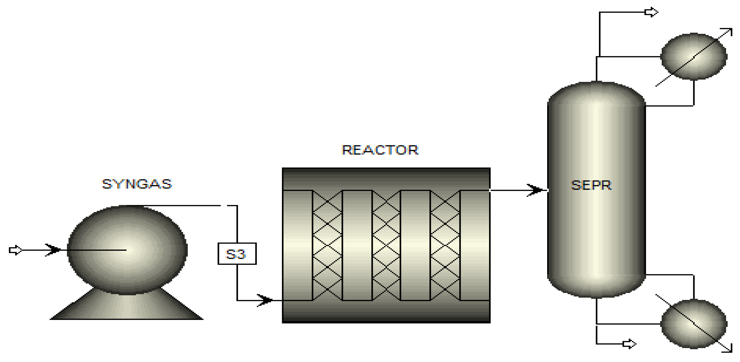
Temperature, catalytic conditions, pressure, gas flow rate, and ratio in moles of CO/H2 are the important factors that were taken into account when designing the reactor. FTS at high or low temperatures, such as (HTFT) and (LTFT), are performed under varied conditions and this may also depend on product composition. Due to a difference in boiling temperatures, heavier components are collected in separator 1, while lighter products are collected in separator 2. To heat the reactor to the desired temperatures, an electric heater is spiraled around the reactor. Figure 1 shows the schematic diagram of the FTS reactor. FTS operation and reactor types are leading factors that control product distribution. Low temperature FTS reactors are classified into tubular fixed bed, micro channel, and slurry bubble column reactors [30]. In this paper, the tubular fixed-bed reactor was selected because of its low cost. In addition, their different characteristics and conversion rates per path are shown in the Table 1.
2.5. Heat Transfer Coefficient
The operative heat transfer coefficient (hwall) is responsible for interacting with solids, liquids, and gases within the reactor tube. Because the volumetric flow rate of liquids is far lower than that of gases, there is very little contact between these two. Because more of the reactor’s wall does not have any liquid contact in flow patterns with less gas to liquid interaction, the hwall approaches solely single-phase (gas to solid) interaction. As a result, the model employs the gas-to-solid heat transfer wall relationship. As a result, the gas/solid equation was employed to model the reactor state [31].
2.6. Parametric Analysis
This model simulates the production of bituminous and lignite coal. The lignite coal data utilized in the model come from the Thar coal literature [32], whereas the coal feed analysis and operating conditions for bituminous coal are from Wen et al. The reactions of devolatilization and pyrolysis were investigated because they can be used to transform coal into gaseous products at high temperatures. Chemisorption reactions were investigated for the removal of CO2 and H2S. Twenty phases were chosen to reach the permitted limitations. Clean goods were fed into the liquefaction reactor. The grade of the coal, heating value, temperature, and pressure all influence the composition of the liquefied yield following pyrolysis and FT reactions [33].
Lower-ranked coals, such as Thar lignite, have more volatile matter (VM) and create more gaseous products with a lower tar content than bituminous coal. Normally, the products of volatiles increase in proportion to the temperature. Increased pressure is also influenced by the composition of product gases. Under ambient conditions, the vacuum pyrolysis of coal produces a higher percentage of heavy hydrocarbons and a lower number of lighter gases. The greater size of particles increases the overall reaction rates as well as minimizes the rates of heat and mass transfer. In terms of quantity and quality, the character of the resulting gases changes dramatically. Table 2 shows the Thar coal composition.
3. Results and Discussion
3.1. Syngas Component Profile “Lignite Coal” Thar Coal Pakistan
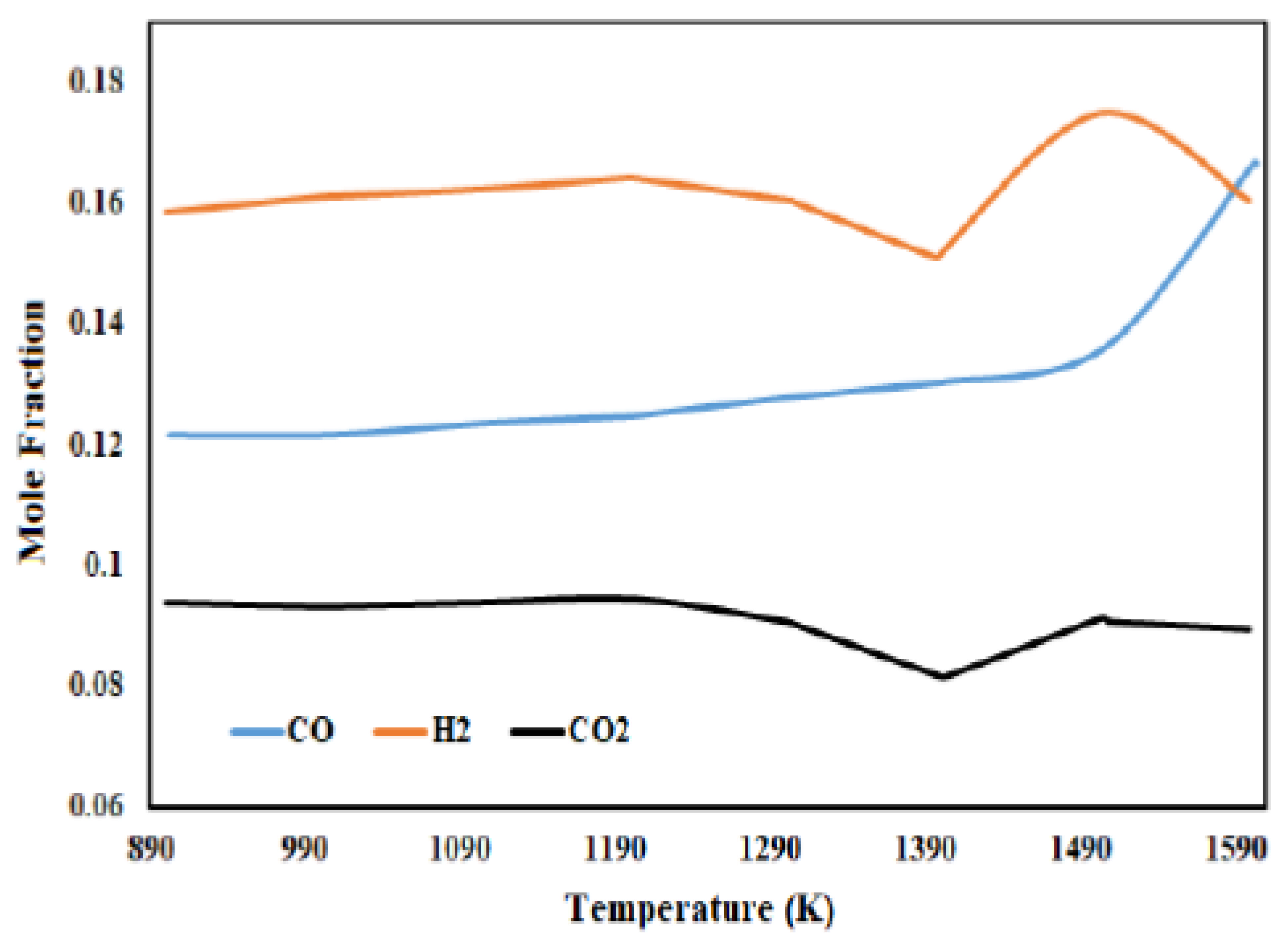
Currently, lignite coal of Thar reserves with a steam/carbon (S/C) mass ratio of 1.48 and an oxygen/carbon (O/C) mass ratio of 0.4 were employed as feed in the gasifier model. The temperature in the pyrolysis zone was 900 K. Individual component profiles were evaluated from top to bottom across the gasifier height, which includes the gasification and combustion zones, at the above-mentioned feed and temperature circumstances. In the gasification zone, the greatest mole fraction of hydrogen (H2), carbon dioxide (CO2), and carbon monoxide (CO) was found. This refers to the high temperature in the combustion zone, resulting in a high value of factor Z, as carbon monoxide (CO) is negligible in less than half of the gasifiers. Figure 2 shows the results of syngas fraction of bituminous coal.
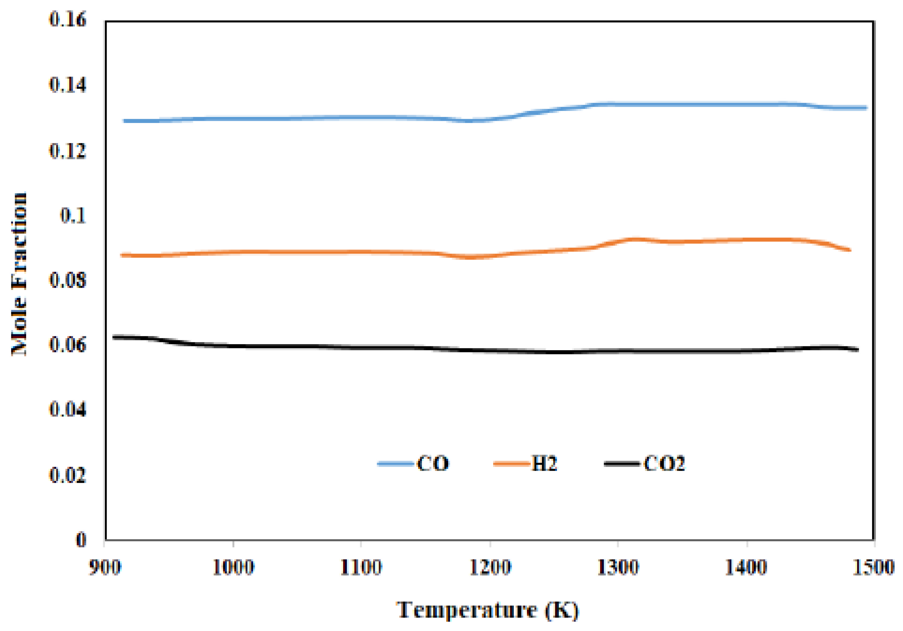
In this region of the gasifier, complete char burning occurred, using the majority of the oxygen supplied as the gasifying medium from the gasifier’s bottom. At the top of the gasification zone, the rate of coal solid flow was highest, and at the bottom of the combustion zone, it was lowest. In lignite-Thar coal, sulfur is at a minimum and is thought to be transformed only to hydrogen sulfide, H2S. The separated gases, which include H2, O2, and N2, were fed into the gasifier’s back end and collected alongside feedstock O2 and H2O. Separated solid components, such as C, S, and ash, were invited to participate in the reactions with RCSTR sequences. Every RCSTR had the same volume, which is equal to the entire gasifier volume divided by the RCSTR sequence number. A heat stream characterized the heat dissipation between the bed and the wall. The concentration of CO dropped at first since the reaction rate was high in the beginning, but subsequently, it stabilized as the reaction rate lowered. It depicts the change in the H2 mole fraction along the reactor’s length. The trend was nearly identical to that of CO, but with a lower slope. This indicates that H2 was the limiting reactant because it was utilized more quickly during the reaction. H2 was converted relatively quickly, which means there was no more hydrogen available for further conversion. As a result, the syngas ratio increased in the quest for an optimal ratio for both hydrogen and carbon monoxide conversion. The loss of hydrogen and carbon monoxide can be predicted using this approach. The syngas ratio and length of the reactor has a great impact on the product yield. For better understanding different syngas ratios vs. reactor length, data were added into the attached Supplementary Information. The syngas ratio of 2.1 was better for complete conversion, and there was a better possibility of obtaining the most products. The limiting reagent was hydrogen when the syngas ratio was held at 2 or below 2; otherwise, CO was the limiting reagent. Figure 3 shows the results of syngas fraction of Thar lignite coal.
3.2. Importance of Steam Flow Rate
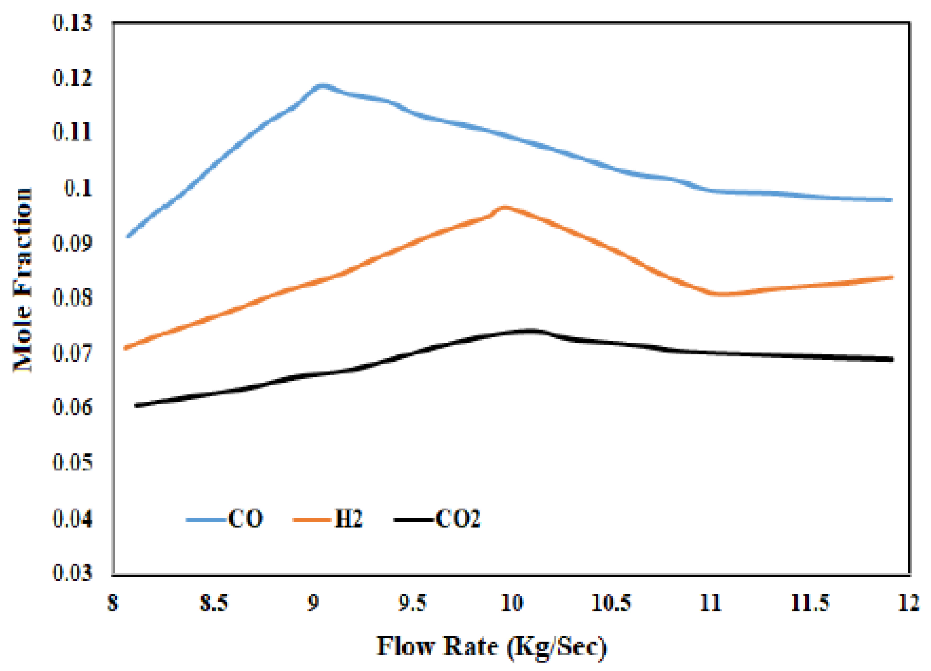
At a constant pyrolysis zone temperature and O/C mass ratio, the steam flow rate was changed for optimization. After the Char-Dec block in the gasification and combustion zone, steam and oxygen were introduced into the model. Because the coal feed contained less oxygen and moisture in the elemental analysis, the S/C and O/C ratios for bituminous coal were kept higher for the parametric analysis. At 15 kg/s, the highest levels of hydrogen and carbon monoxide in the resulting gas were reached. The temperature of the product outlet gas was 989 K. The mass ratio of steam to coal was 2.8 to 4, while the mass ratio of oxygen to coal was 0.64. The resultant gas had a mass enthalpy of 8.64 MJ/kg. Figure 4 shows the results of syngas fraction of Thar lignite coal with constant steam flow rate.
3.3. Optimization of Steam Flow with Thar Coal
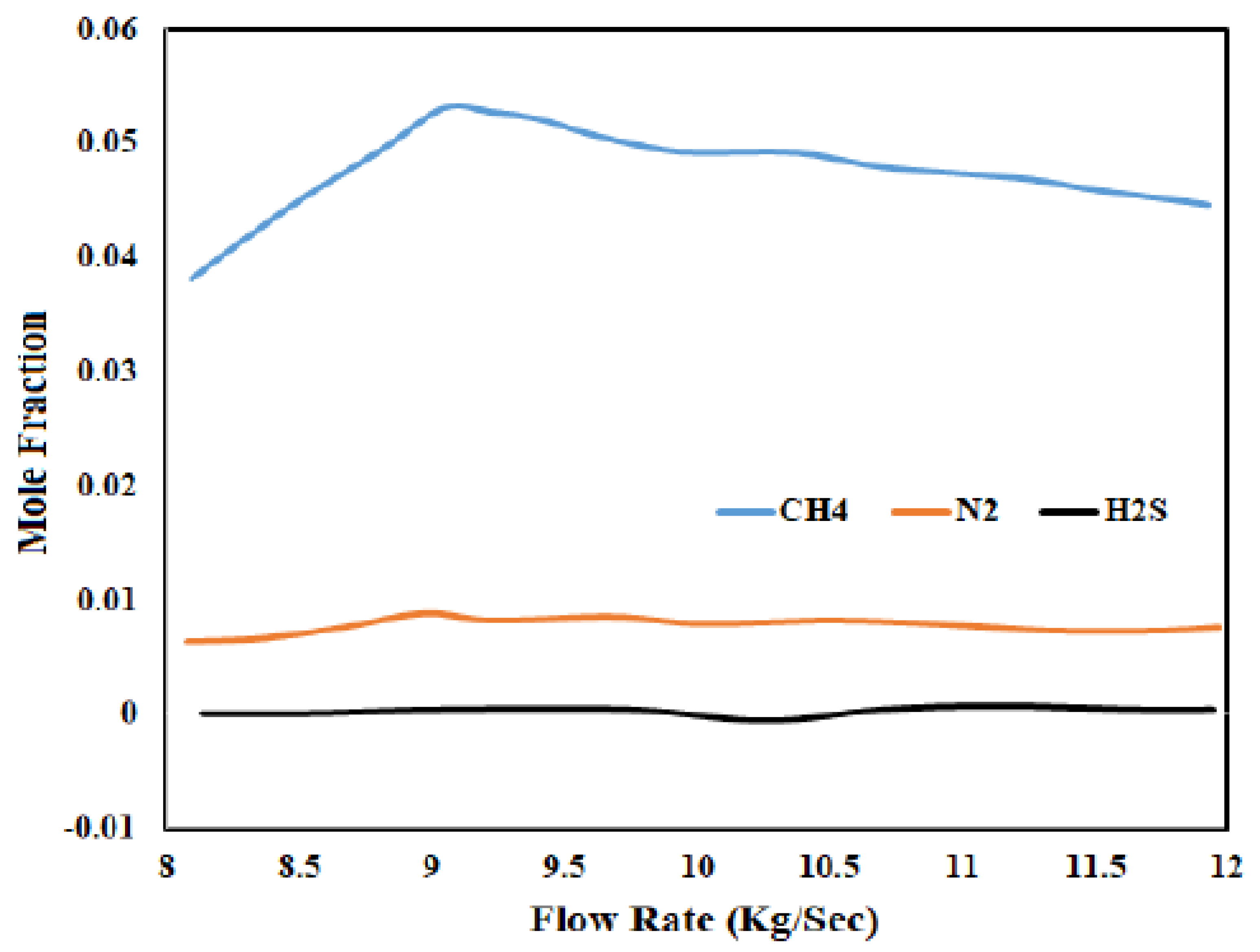
At a constant pyrolysis zone temperature and an O/C mass rate, the steam flow rate was changed for optimization. For the parametric analysis of lignite coal, the S/C and O/C ratios were kept low because the coal supply already contained higher oxygen and moisture in the elemental analysis. At 9 kg/s, the highest levels of hydrogen and carbon monoxide in the resulting gas were reached. The temperature of the product’s output gas was 1009 K. The mass ratio of steam to coal was 1.48 to 2.22, and the mass ratio of oxygen to coal was 0.4. The resultant gas had a mass enthalpy of 7.5 MJ/kg. Figure 5 shows the gaseous fraction of Thar lignite coal.
3.4. Product Yield
The FTS model received syngas for product liquefaction at a 9 kg/s optimum flow rate. At 0.00132 kg/s, diesel fractions were produced. Thar has a total of 175 million tons of coal reserves. This massive amount of coal, according to the model, can be transformed into 123.22 million barrels of diesel. This variant produces the most diesel (C12+ hydrocarbon production), which is the reactor’s most desirable product. The yield of methane, an unwanted product, was not very high and can be further lowered in optimized conditions. The produced CO2, which is a GHG and a by-product of the FTS process during the water gas shift reaction, was also minimized to a permissible limit, just as it is in the gas cleaning system, and can be further reduced by up to 98 percent. The length of the tube depicts the conversion’s eligibility requirements. Figure 6 illustrates the product yield of diesel C12 to C15 hydrocarbons, which was highest at a reactor length of 30 sccm in the model. During FTS, gasoline is the least preferred hydrocarbon, while C12+ hydrocarbons, which are mostly diesel, are the most desirable. The findings show that utilizing a catalyst with a promotor and activator in a fixed bed reactor for FTS results in a higher hydrocarbon output.
3.5. Reduction of GHG Emissions in CTL FTS Process
Pakistan is a country with a huge coal reserve, which has not been used extensively as an energy source, and with the continuing upward trend in crude oil prices, the possibility of producing syngas for liquid fuel using the FTS process has been gaining much importance for energy security in the country. Although the CTL FTS process is environmentally friendly in most respects, it produces much more GHG emissions [34] when compared to processes of petroleum refining producing the same fuels. The challenge of efficient utilization and the green processing of coal at a manageable cost is of interest to many research scholars nowadays. There are several processes that are also technologically proven, through which this CTL FTS process can be transformed into producing low to almost zero GHG emissions.
The most important process to reduce GHG emissions from coal to produce liquid fuel is adapting to the carbon capture process. One preprocess measure that can be taken to reduce carbon footprints in the CTL FTS process is adding a moderate amount of biomass to coal for liquid production. The coal-biomass to liquid (CBTL) process has been practiced not only for its carbon neutrality, but this process also has been catalyzed for its low cost. In the operational process, syngas is produced in the biomass/coal-fed co-gasifier, then the H/C ratio is achieved in the water gas shift (WGS) reaction, which is needed in the syngas feed to the FT unit. Using a dual-stage selective physical solvent-based process, a considerable amount of CO2 can be captured before the FT reactor. In the FT unit, a Fe-based catalyst is used in the low-temperature FT (LTFT) reactor; however, in the case of the post-FT carbon capture process, three technologies, namely Selexol, monoethanolamine (MEA), and methyl diethanolamine/piperazine (MDEA/PZ) technologies are preferred [35].
Another process includes the catalytic dehydrogenation (CDH) of liquid fuels from coal to minimize carbon emissions, and this process is applicable where syngas produced from coal has a lower H/C ratio. Using a water gas shift (WGS) reaction for obtaining a higher H/C ratio results in the production of large GHG emissions. In this process, the catalytic dehydrogenation of gaseous C1–C4 products of FT synthesis and the recycling of hydrogen to the syngas steam results in a higher H/C ratio with little or no carbon emissions. All carbon removed from this process is in the form of value-added by-products, also called multi-walled carbon nanotubes (MWCNT), which can also be utilized in many applications such as removing toxic metals and being used in fire retardant coatings and in fibers and ropes for use in transmission lines and cables, etc. [36].
The other process includes the use of Underground Coal Gasification (UCG) technology. This process is mainly utilized in power plants for the generation of electricity; however, UCG is also an attractive option for the CTL FTS process, not only in protecting the environment from hazardous gases but also in terms of economic gains. Preliminary studies conducted in the Thar block of Pakistan have already shown some positive signs of this technology [37]. UCG gasifies coal seams into syngas in situ and extracts the syngas to the surface for its subsequent use. In this way, coal is utilized efficiently in old mines and deep coal seams, and more importantly, the coal ash, residues, and other pollutants left after coal gasification remain below the ground [38].
The production of CO2 is highly dependent on the temperature and pressure conditions, the type of reactor, and the catalyst of the FTS reactor. Measures are taken, such as the low temperature Fischer Tropsch reactor, to mitigate the CO2 production. The condition for CO2 conversion is favored by the Boudourd Reaction.
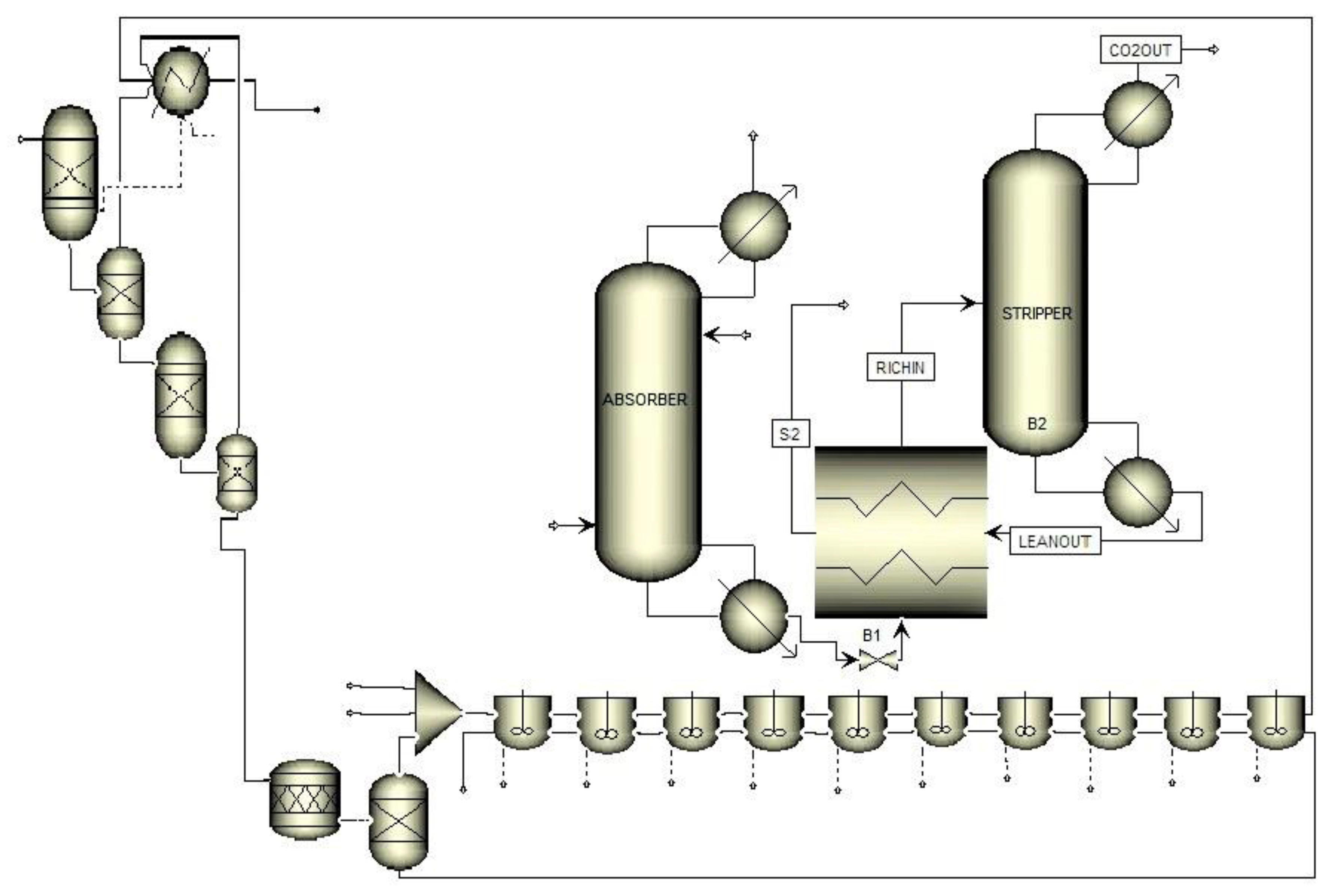
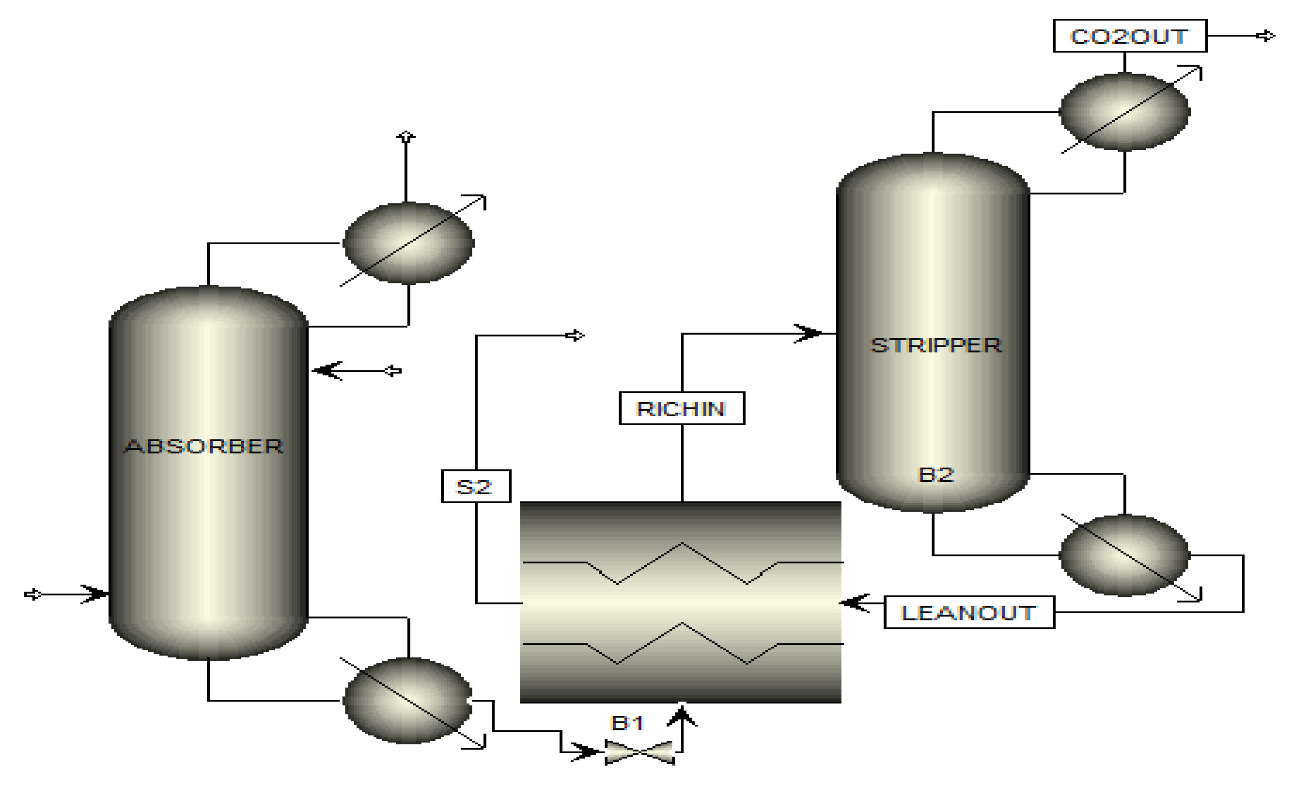
In any case, it is unlikely that this reaction is able to remove all of the carbon dioxide. Amine treatment is used to capture the surplus CO2, which is recovered to 98% approx. Figure 7 shows the amine treatment process in Aspen Plus. Captured CO2 is utilized by first being sequestrated into the deep sea by shipping it there. Secondly, it can be used in geological formations. Thirdly, it can be used for enhanced oil recovery. Lastly, it can be used in many industrial processes. There are a variety of techniques present in the market for the removal of problem-creating materials, but in our case, CO2 and H2S are available for troubleshooting. An aqueous solution of alkyl-amine solution is used to eradicate these gases. The world is confronted with issues such as global warming and climate change. In order to overcome this difficulty, the control of emissions such as CO2 is essential. Therefore, the world is speculating about carbon capture and storage techniques and processes.
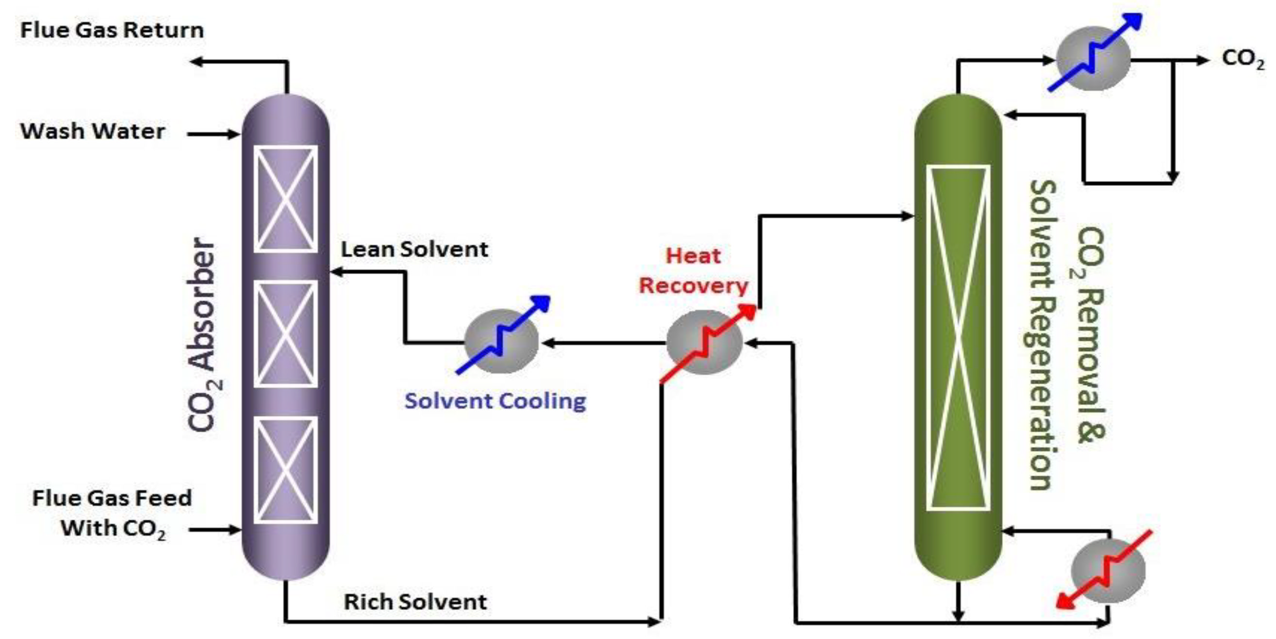
Amine treatment is one of the most dedicated technologies for the handling of CO2 and H2S from hydrocarbon streams. This process is known as acid gas removal (AGR) or the sweetening process. For this purpose, different primary, secondary, and tertiary solvents such as mono-ethanolamine (MEA) and di-ethanolamine (DEA) are extensively utilized for acid gas removal. The purification percentage achieved by this process is ninety-eight, which is a bigger achievement regarding CO2 recovery. In general, MEA has the specialty of eradicating CO2 and H2S. Though DEA and MDEA are more appropriate in terms of economics and corrosive properties, solvents were developed to be more prevalent. CO2 capture and H2S removal are very crucial for many industries and power plants, such as the steel industry, cement industry, iron industry, food industry, tobacco industry, and chemical industries. The flue gas/sour gas is fed to the contactor tower and rises to the descending Diethanol amine solution. After absorption, the sweet gas flows out from the top of the tower, and the remaining amine solution is perceived as a rich solution as it carries the gases absorbed in it. The second step is the heat exchange, through which both lean and rich amines pass. The rich amine obtains heat while the lean is cooled down. This rich amine is further heated by the steam provided by the reboiler in the regeneration unit. This stripping process untightened the CO2 and H2S gases, and the amine was regenerated, recycled, and reused throughout the cycle. For a better understanding, the following Figure 8 (dedicated to carbon dioxide removal) describes the acid gas removal process [39,40].
Coal to liquids via the FTS process is an alternative technology for oil production, utilizing vast Thar coal resources in Pakistan. The technology can also play a key role in countering booming imports of these hydrocarbon liquids in the country. However, energy usage and GHG emissions of FTS plants are relatively very high due to their long-chain production and low energy efficiency in the energy cycle.
Processes such as CCS and CDH can be an economic and environmentally friendly way for coal-to-liquid, technology which simultaneously satisfies the requirements of hydrocarbon liquid supply and CO2 emissions reduction in Pakistan. In 2020, CO2 emissions for Pakistan were 217 million tons. Between 1971 and 2020, CO2 emissions in Pakistan grew substantially from 18.1 to 217 million tons, rising at an increasing annual rate that reached a maximum of 15.38% in 1987 and then decreased to −0.43% in 2020. From 153,083.7 million tons to 56,152 million tons, CO2 emissions were also reduced. Every single unit in Pakistan follows the SOPs to deal with greenhouse gases. Chemical equilibrium is of great importance when considering the condition of chemical equilibrium. By controlling this reaction, gas composition can be altered as it follows thermodynamic applications, which is quite an easy task. The type of gasifier, the hydrogen to carbon monoxide ratio, and the conditions where the gasifier operates play a very critical role pertaining to shift reaction. This shift reaction has a very small impact on heating value. One of the discrete features of fixed-bed gasifiers is that an nH2/CO ratio of 1.7 to 2.0 is formed straight, which is appropriate for the Fischer–Tropsch synthesis without the need for extra water–gas shift change to regulate the H2/CO ratio, and this embraces a price benefit.
3.6. Discussion
The FTS prototype can detect the trend of n-paraffins as well as the conversion of hydrogen and carbon monoxide. The FTS kinetics are said to be particularly difficult to understand. It sells gasoline, diesel, alcohol, aldehyde, ketone, waxes, and a variety of other items. N-paraffins and 1-olefins are found in primary products, while branched hydrocarbons, 2-olefins, and oxygenates are found in secondary products. Temperature, pressure, flow velocity, and catalyst conditions are all controlled to create the desired results. In this method of synthesis, the catalyst plays an important role in creating the desired product. WGS activity and olefin content are high in cobalt and ruthenium catalysts, and cobalt and ruthenium create ore waxy products. These catalysts can be used to convert CO to methane. Small additions can be added to the catalyst to help it reduce and therefore increase activity.
Pakistan coal reserves in Thar (Sindh) regarded as the largest coal reserves in Asia, carry around 175 billion tons of Coal reserves at this location. Many analyses and studies have been conducted to estimate the total energy output that can be produced from this coal source in the form of electricity generation and other forms of energy means. One study revealed that the estimated coal reserves are capable of producing 100,000 MW of power for the next 250 years. The exploitation of this source also means that Pakistan’s long-term energy planning would also attract foreign direct investment and reduce the country’s dependence on imported fuel for the sustainable development of energy needs [41]. However, the use of coal is also considered the biggest source of greenhouse gas (GHG) emissions, and coal ash residue, which is the large volume of waste produced by coal-fired power plants, signifies a high potential for global warming and environmental contamination [42,43].
Although, in the wake of new technology, the green and sustainable processing of coal utilization has become possible with negligible negative impacts on the environment. One such technology is coal to liquid (CTL), in which coal is converted into valuable liquid hydrocarbons through a proven method known as the Fischer-Tropsch synthesis (FTS) process. From its initial days of development, the FTS process has improved through improved catalyst selection. Preliminary studies of the FTS process for coal utilization and its conversion to liquid fuels have also been performed in Pakistan [37].
The FTS process commercialization and its cost estimation depend mainly on the price of the products, i.e., hydrogen (H2) and carbon dioxide (CO2) obtained from the FTS process. Detailed performance analysis has been carried out for a broad range of prices for H2 and CO2, and for the range of potential CO2 credits, the results revealed that the H2 price has the largest impact on the selling price of FT fuels. Hence, the commercialization prospects of the FTS process in any country could focus on improving the H2 and CO2 recycle contributions and FT fuel conversion ratio [44].
Pakistan plans to increase the use of environmentally friendly technologies and renewable energy for power generation in the energy mix. the country has been increasing efforts to reduce the overall impact of climate-induced vulnerabilities, while also considering that Pakistan has only a little share of global GHG emissions. Projects, such as the Ten Billion Tsunami Programme, are governed by the Pakistan Ministry of Climate Change [21], and they pledged to set an overall target of 50% reduction of emissions by 2030, along with aiming to increase their share of using electric vehicles to 30%. Shifting their 60% power generation capacity on renewable energy in its Nationally Determined Contributions (NDC) is very ambitious [45].
4. Conclusions
Despite international sanctions, and restrictions on its use, coal can still play a big role in taming the energy crisis in Pakistan. The use of Thar coal in its compositional rank has many limitations associated with environmental impacts and thermal efficiency; however, technology such as CTL with the help of the FT method allows this source of energy to utilize a more clean and sustainable form for the production of efficient liquid fuel of energy. As much-needed attention has been given to climate change and GHG emissions, the production capacity of CTL has increased in the last few years around the world. However, the technology has not been fully commercialized yet, which makes it difficult to estimate the economic parameters of the operation of CTL with FT with or without a carbon capture system. Pakistan’s recently announced NDC targets aim to shift to 60% on renewable energy in power generation by 2030, along with a complete ban on imported coal; hence, in the context of this undertaking, there is a dire need to use new and critical technologies such as CTL, which has the potential to uplift domestic coal resources and meet the energy needs of the country. Pakistan benefitted economically from CPEC with their financing of coal-fired power plants, which also helped to solve the electricity shortage in the country, but that also comes at the cost of environmental harm. Hence, it would be prudent to change direction a little because, instead of obtaining financing for imported coal-fired power plants, energy projects that involve the use of coal must implement CTL technology, which should also be designed to maximize the efficiency of water use. At the policy level, the policy that favors boosting the indigenous energy resources of the host country is also the need of the hour, which also removes any barriers that come in the way of making Pakistan a key player in low carbon development.
Supplementary Materials
The following supporting information can be downloaded at: https://0-www-mdpi-com.brum.beds.ac.uk/article/10.3390/c8040063/s1.
Author Contributions
Conceptualization, writing—original draft, formal analysis: B.B.; funding acquisition, investigation, methodology: A.G.F. and Z.U.R.F.; project administration, resources, visualization, supervision, writing—review and editing: M.A. All authors have read and agreed to the published version of the manuscript.
Funding
This research received no external funding.
Institutional Review Board Statement
Not applicable.
Informed Consent Statement
Not applicable.
Data Availability Statement
The data is presented in the present research article.
Acknowledgments
The authors appreciate the technical support by NFC, Multan by providing software facility.
Conflicts of Interest
The authors declare no conflict of interest.
References
- BP. BP Statistical Review of World Energy globally consistent data on world energy markets and authoritative publications in the field of energy. In BP Energy Outlook; BP: London, UK, 2021; Volume 70, pp. 8–20. [Google Scholar]
- Amin, M.; Shah, H.H.; Fareed, A.G.; Khan, W.U.; Chung, E.; Zia, A.; Farooqi, Z.U.R.; Lee, C. Hydrogen production through renewable and non-renewable energy processes and their impact on climate change. Int. J. Hydrogen Energy 2022, 47, 33112–33134. [Google Scholar] [CrossRef]
- Johnsson, F.; Kjärstad, J.; Rootzén, J. The threat to climate change mitigation posed by the abundance of fossil fuels. Clim. Policy 2018, 19, 258–274. [Google Scholar] [CrossRef] [Green Version]
- Kanwal, S.; Mehran, M.T.; Hassan, M.; Anwar, M.; Naqvi, S.R.; Khoja, A.H. An integrated future approach for the energy security of Pakistan: Replacement of fossil fuels with syngas for better environment and socio-economic development. Renew. Sustain. Energy Rev. 2021, 156, 111978. [Google Scholar] [CrossRef]
- Mukherjee, S.; Rajabi, M.; Esterle, J. Relationship between coal composition, fracture abundance and initial reservoir permeability: A case study in the Walloon Coal Measures, Surat Basin, Australia. Int. J. Coal Geol. 2021, 240, 103726. [Google Scholar] [CrossRef]
- Jaffri, G.-R.; Zhang, J. Catalytic gasification of Pakistani Lakhra and Thar lignite chars in steam gasification. J. Fuel Chem. Technol. 2009, 37, 11–19. [Google Scholar] [CrossRef]
- BP. BP Statistical Review of World Energy Globally Consistent Data on World Energy Markets; BP: London, UK, 2022. [Google Scholar]
- Shar, M.A.; Mahesar, A.A. Natural gas potential of Pakistan an important parameter in mitigating greenhouse gas emissions. Pak. J. Anal. Environ. Chem. 2020, 21, 209–218. [Google Scholar] [CrossRef]
- Nel, W.P.; Cooper, C.J. Implications of fossil fuel constraints on economic growth and global warming. Energy Policy 2009, 37, 166–180. [Google Scholar] [CrossRef]
- Lin, S.; Sun, W.; Guo, L.; Cheng, P.; Sun, Y.; Zhang, H. Development of a reduced mechanism of a three components surrogate fuel for the coal-to-liquid and diesel combustion simulation. Fuel 2021, 294, 120370. [Google Scholar] [CrossRef]
- Zhang, H.; Sun, W.; Guo, L.; Yan, Y.; Li, J.; Lin, S.; Wang, Q.; Sun, Y. An experimental study of using coal to liquid (CTL) and diesel as pilot fuels for gasoline dual-fuel combustion. Fuel 2020, 289, 119962. [Google Scholar] [CrossRef]
- Ma, G.; Wang, X.; Xu, Y.; Wang, Q.; Wang, J.; Lin, J.; Wang, H.; Dong, C.; Zhang, C.; Ding, M. Enhanced Conversion of Syngas to Gasoline-Range Hydrocarbons over Carbon Encapsulated Bimetallic FeMn Nanoparticles. ACS Appl. Energy Mater. 2018, 1, 4304–4312. [Google Scholar] [CrossRef]
- Dry, M. Catalytic aspects of industrial Fischer-Tropsch synthesis. J. Mol. Catal. 1982, 17, 133–144. [Google Scholar] [CrossRef]
- Martínez-Vargas, D.X.; Sandoval-Rangel, L.; Campuzano-Calderon, O.; Flores, M.R.; Lozano, F.J.; Nigam, K.D.P.; Mendoza, A.; Montesinos-Castellanos, A. Recent Advances in Bifunctional Catalysts for the Fischer–Tropsch Process: One-Stage Production of Liquid Hydrocarbons from Syngas. Ind. Eng. Chem. Res. 2019, 58, 15872–15901. [Google Scholar] [CrossRef]
- Sirikulbodee, P.; Ratana, T.; Sornchamni, T.; Phongaksorn, M.; Tungkamani, S. Catalytic performance of Iron-based catalyst in Fischer–Tropsch synthesis using CO2 containing syngas. Energy Procedia 2017, 138, 998–1003. [Google Scholar] [CrossRef]
- Zhou, L.; Duan, M.; Yu, Y. Exergy and economic analyses of indirect coal-to-liquid technology coupling carbon capture and storage. J. Clean. Prod. 2017, 174, 87–95. [Google Scholar] [CrossRef]
- Yang, S.; Xiao, Z.; Deng, C.; Liu, Z.; Zhou, H.; Ren, J.; Zhou, T. Techno-economic analysis of coal-to-liquid processes with different gasifier alternatives. J. Clean. Prod. 2020, 253, 120006. [Google Scholar] [CrossRef]
- Eddy, N.O.; Ibok, U.J.; Garg, R.; Garg, R.; Iqbal, A.; Amin, M.; Mustafa, F.; Egilmez, M.; Galal, A.M. A Brief Review on Fruit and Vegetable Extracts as Corrosion Inhibitors in Acidic Environments. Molecules 2022, 27, 2991. [Google Scholar] [CrossRef] [PubMed]
- Amin, M.; Shah, H.H.; Iqbal, A.; Farooqi, Z.U.R.; Krawczuk, M.; Zia, A. Conversion of Waste Biomass into Activated Carbon and Evaluation of Environmental Consequences Using Life Cycle Assessment. Appl. Sci. 2022, 12, 5741. [Google Scholar] [CrossRef]
- Amin, M.; Chung, E.; Shah, H.H. Effect of different activation agents for activated carbon preparation through characterization and life cycle assessment. Int. J. Environ. Sci. Technol. 2022, 1–12. [Google Scholar] [CrossRef]
- Ministry of Climate Change. Available online: https://mocc.gov.pk/ProjectDetail/M2QzOWJmMjUtZTU3MC00NmFkLWE4YmMtZDFhMmRlOGU2NGRh (accessed on 4 August 2022).
- Mehdi, S.N.; Khan, Z.M.; Farid, H.U.; Hussain, S. Investigating Compatible Drying Technique for Safe Utilization of Thar Coal, Pakistan. Int. J. Coal Prep. Util. 2021, 42, 3303–3324. [Google Scholar] [CrossRef]
- Fletcher, T.H.; Kerstein, A.R.; Pugmire, R.J.; Solum, M.S.; Grant, D.M. Chemical percolation model for devolatilization. 3. Direct use of carbon-13 NMR data to predict effects of coal type. Energy Fuels 1992, 6, 414–431. [Google Scholar] [CrossRef]
- Suuberg, E.M.; Peters, W.A.; Howard, J.B. Product Composition and Kinetics of Lignite Pyrolysis. Ind. Eng. Chem. Process Des. Dev. 1978, 17, 37–46. [Google Scholar] [CrossRef]
- Kulkarni, M.; Ganguli, R. Moving Bed Gasification of Low Rank Alaska Coal. J. Combust. 2012, 2012, 918754. [Google Scholar] [CrossRef] [Green Version]
- Claeys, M.; van Steen, E. Basic Studies. Stud. Surf. Sci. Catal. 2004, 152, 601–680. [Google Scholar] [CrossRef]
- Amin, M.; Munir, S.; Iqbal, N.; Wabaidur, S.M.; Iqbal, A. The Conversion of Waste Biomass into Carbon-Supported Iron Catalyst for Syngas to Clean Liquid Fuel Production. Catalysts 2022, 12, 1234. [Google Scholar] [CrossRef]
- Pöhlmann, F.; Jess, A. Influence of Syngas Composition on the Kinetics of Fischer-Tropsch Synthesis of using Cobalt as Catalyst. Energy Technol. 2015, 4, 55–64. [Google Scholar] [CrossRef]
- Mahmood, S.; Iqbal, A.; Din, R.U.; Wadood, A.; Mateen, A.; Amin, M.; Yahia, I.S.; Zahran, H.Y. Influence of Homogenizing Methodology on Mechanical and Tribological Performance of Powder Metallurgy Processed Titanium Composites Reinforced by Graphene Nanoplatelets. Molecules 2022, 27, 2666. [Google Scholar] [CrossRef] [PubMed]
- Akhtar, A.; Pareek, V.K.; O Tade, M. Modern Trends in CFD Simulations: Application to GTL Technology. Chem. Prod. Process Model. 2006, 1. [Google Scholar] [CrossRef]
- Fratalocchi, L.; Visconti, C.G.; Groppi, G.; Lietti, L.; Tronconi, E. Intensifying heat transfer in Fischer-Tropsch tubular reactors through the adoption of conductive packed foams. Chem. Eng. J. 2018, 349, 829–837. [Google Scholar] [CrossRef]
- Sarwar, A.; Khan, M.N.; Azhar, K.F. Coal Chemistry and Morphology of Thar Reserves, Pakistan. J. Miner. Mater. Charact. Eng. 2012, 11, 817–824. [Google Scholar] [CrossRef]
- Makhura, E.; Rakereng, J.; Rapoo, O.; Danha, G. Effect of the operation parameters on the Fischer Tropsch synthesis process using different reactors. Procedia Manuf. 2019, 35, 349–355. [Google Scholar] [CrossRef]
- Amin, M.; Shah, H.H. Effect of Absorption Time for the Preparation of Activated Carbon from Wasted Tree Leaves of Quercus alba and Investigating Life Cycle Assessment. C 2022, 8, 57. [Google Scholar] [CrossRef]
- Jiang, Y.; Bhattacharyya, D. Plant-wide modeling of an indirect coal–biomass to liquids (CBTL) plant with CO2 capture and storage (CCS). Int. J. Greenh. Gas Control 2014, 31, 1–15. [Google Scholar] [CrossRef] [Green Version]
- Huffman, G.P. Incorporation of catalytic dehydrogenation into Fischer–Tropsch synthesis of liquid fuels from coal to minimize carbon dioxide emissions. Fuel 2011, 90, 2671–2676. [Google Scholar] [CrossRef]
- Nawaz, Z.; Ramzan, N.; Nawaz, S.; Naveed, S.; Khan, M.B. Green Processing of Coal to Liquid Fuels: Pakistan’s Perspective. Pak. Acad. Sci. 2012, 49, 165. [Google Scholar]
- Feng, Y.; Yang, B.; Hou, Y.; Duan, T.-H.; Yang, L.; Wang, Y. Comparative environmental benefits of power generation from underground and surface coal gasification with carbon capture and storage. J. Clean. Prod. 2021, 310, 127383. [Google Scholar] [CrossRef]
- Bińczak, G.; Pohorecki, R.; Moniuk, W.; Możeński, C. Amine activators of CO2 absorption in industrial conditions. Chem. Process Eng. 2019, 40, 157–165. [Google Scholar]
- Konopacka-Łyskawa, D.; Czaplicka, N.; Szefer, A. CaO-based high temperature CO2 sorbents–Literature review. Chem. Process Eng.-Inżynieria Chem. I Proces 2021, 42, 411–438. [Google Scholar]
- Raza, M.A.; Khatri, K.L.; Memon, M.A.; Rafique, K.; Haque, M.I.U.; Mirjat, N.H. Exploitation of Thar coal field for power generation in Pakistan: A way forward to sustainable energy future. Energy Explor. Exploit. 2022, 40, 1173–1196. [Google Scholar] [CrossRef]
- Farooqi, Z.U.R.; Ahmad, I.; Ditta, A.; Ilic, P.; Amin, M.; Naveed, A.B.; Gulzar, A. Types, sources, socioeconomic impacts, and control strategies of environmental noise: A review. Environ. Sci. Pollut. Res. 2022, 29, 81087–81111. [Google Scholar] [CrossRef]
- Lemly, A.D. Environmental hazard assessment of coal ash disposal at the proposed Rampal power plant. Hum. Ecol. Risk Assess. Int. J. 2017, 24, 627–641. [Google Scholar] [CrossRef]
- Zang, G.; Sun, P.; Elgowainy, A.A.; Bafana, A.; Wang, M. Performance and cost analysis of liquid fuel production from H2 and CO2 based on the Fischer-Tropsch process. J. CO2 Util. 2021, 46, 101459. [Google Scholar] [CrossRef]
- UNFCCC. Paksitan Updated NDC 2021; UNFCCC: Bonn, Germany, 2021. [Google Scholar]
Figure 1.
FTS Reactor.

Figure 2.
Syngas fraction of bituminous coal.

Figure 3.
Syngas fraction of Thar lignite coal.

Figure 4.
Syngas fraction of Thar lignite coal.

Figure 5.
Gaseous fraction of lignite Thar coal.

Figure 6.
FTS Model.

Figure 7.
Amine treatment process in ASPEN Plus.

Figure 8.
General process diagram for the amine treatment process.


Table 1.
Reactor properties.
| Reactor | Conversion per Path (%) | Capacity per Reactor (bbl/day) | Characteristics |
|---|---|---|---|
| Tubular fixed-bed | 30–35 | ≤6000 | ≤30,000 tubes with catalyst pellet or extradites |
Table 2.
Thar coal composition.
| Content | Carbon | Oxygen | Hydrogen | Sulphur | Nitrogen | Moisture | Ash |
|---|---|---|---|---|---|---|---|
| (%) | 27.1 | 11.0 | 2.1 | 1.4 | 0.4 | 38 | 20 |
Publisher’s Note: MDPI stays neutral with regard to jurisdictional claims in published maps and institutional affiliations. |
© 2022 by the authors. Licensee MDPI, Basel, Switzerland. This article is an open access article distributed under the terms and conditions of the Creative Commons Attribution (CC BY) license (https://creativecommons.org/licenses/by/4.0/).
Share and Cite
MDPI and ACS Style
Bashir, B.; Amin, M.; Fareed, A.G.; Farooqi, Z.U.R. Conversion of Coal-Biomass into Diesel by Using Aspen Plus. C 2022, 8, 63. https://0-doi-org.brum.beds.ac.uk/10.3390/c8040063
AMA Style
Bashir B, Amin M, Fareed AG, Farooqi ZUR. Conversion of Coal-Biomass into Diesel by Using Aspen Plus. C. 2022; 8(4):63. https://0-doi-org.brum.beds.ac.uk/10.3390/c8040063
Chicago/Turabian StyleBashir, Bilal, Muhammad Amin, Anaiz Gul Fareed, and Zia Ur Rahman Farooqi. 2022. "Conversion of Coal-Biomass into Diesel by Using Aspen Plus" C 8, no. 4: 63. https://0-doi-org.brum.beds.ac.uk/10.3390/c8040063
Note that from the first issue of 2016, this journal uses article numbers instead of page numbers. See further details here.