Reverse Water Gas Shift by Chemical Looping with Iron-Substituted Hexaaluminate Catalysts


Chemical Engineering Department Blechner Center for Industrial Catalysis and Process Development, Ben-Gurion University of the Negev, Beer-Sheva 84105, Israel
*
Author to whom correspondence should be addressed.
Catalysts 2020, 10(9), 1082; https://0-doi-org.brum.beds.ac.uk/10.3390/catal10091082
Submission received: 24 August 2020
/
Revised: 13 September 2020
/
Accepted: 16 September 2020
/
Published: 18 September 2020
Abstract
:The Fe-substituted Ba-hexaaluminates (BaFeHAl) are active catalysts for reverse water-gas shift (RWGS) reaction conducted in chemical looping mode. Increasing of the degree of substitution of Al3+ for Fe3+ ions in co-precipitated BaHAl from 60% (BaFeHAl) to 100% (BaFe-hexaferrite, BaFeHF), growing its surface area from 5 to 30 m2/g, and promotion with potassium increased the CO capacity in isothermal RWGS-CL runs at 350–450 °C, where the hexaaluminate/hexaferrite structure is stable. Increasing H2-reduction temperature converts BaFeHAl to a thermally stable BaFeHF modification that contains additional Ba-O-Fe bridges in its structure, reinforcing the connection between alternatively stacked spinel blocks. This material displayed the highest CO capacity of 400 µmol/g at isothermal RWGS-CL run conducted at 550 °C due to increased concentration of oxygen vacancies reflected by greater surface Fe2+/Fe3+ ratio detected by XPS. The results demonstrate direct connection between CO capacity measured in RWGS-CL experiments and calculated CO2 conversion.
1. Introduction
CO2 can be converted to syngas, a key intermediate in production of green chemicals and fuels [1,2], by reverse water-gas shift (RWGS). Catalysts for this reaction are Cu, Ce, Ni, Fe-based oxides as well as supported noble metals (Pt, Rh), and multicomponent metal oxides [1,2,3,4,5,6]. The reaction is reversible and endothermic, thus it yields relatively low conversion at equilibrium at <600 °C. The shortcoming of those catalysts is significant methanation activity reducing the yield of carbon oxide at high temperatures [6].
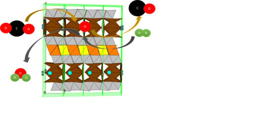
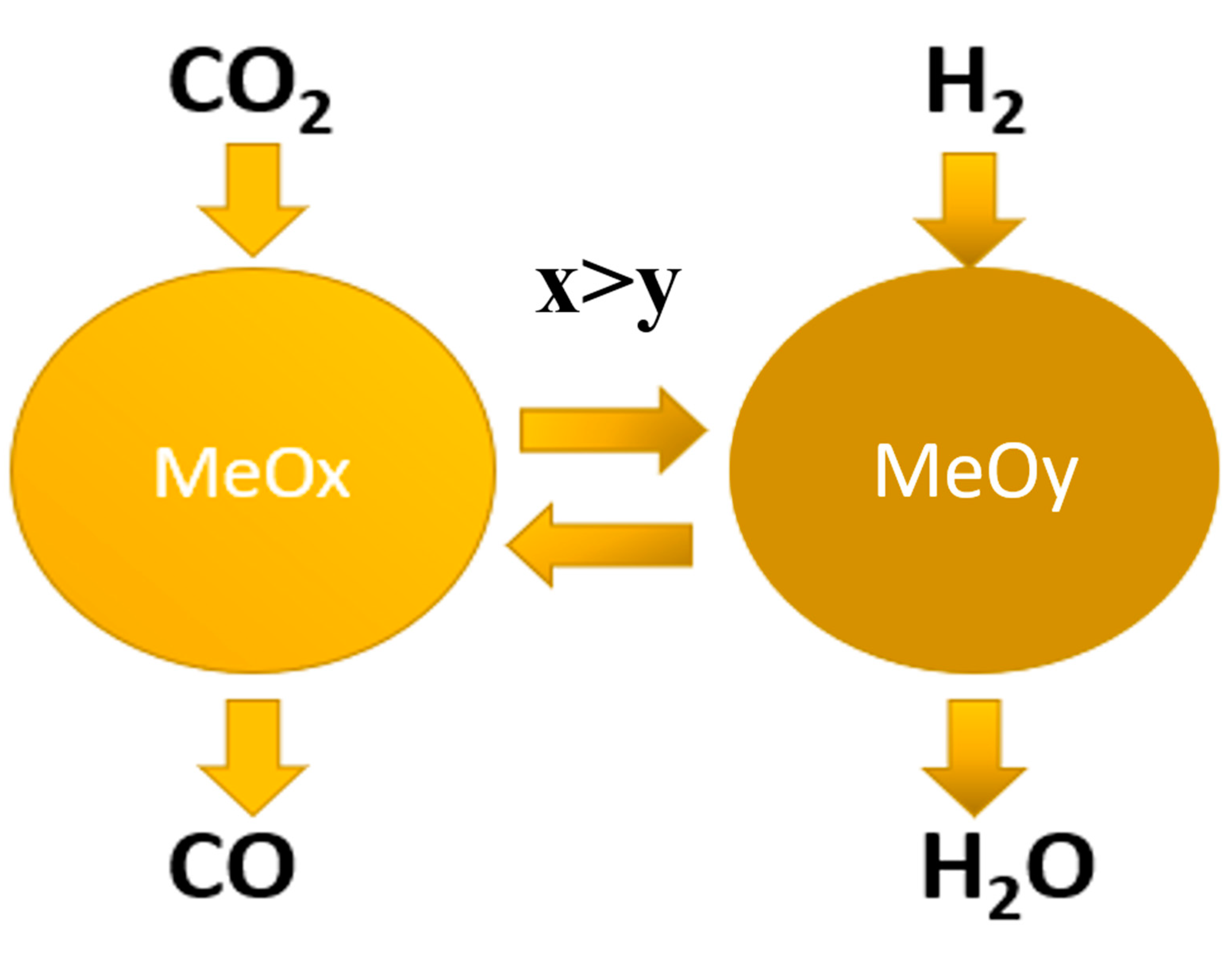
Chemical looping (CL) combined two separate steps: hydrogen reduction of metal oxide catalyst followed by CO2 oxidation of the catalyst to produce CO (Scheme 1). Each one of the two catalytic steps is not thermodynamically limited, thus complete conversion of CO2 can be accomplished at relatively low temperature. Furthermore, since CO and H2 are not present simultaneously on the catalyst surface, no methanation is expected. Metal oxide catalytic materials suitable for RWGS-CL should have the ability to eliminate oxygen from materials surface for efficient splitting of C–O bond of CO2 during adsorption on O-vacancies at surface of the catalyst. It is important to maximize the surface area and surface concentration of suitable O-vacancies governed by cationic environment of precursor oxygen ions.
Iron oxides display natural abundance and high re-oxidation capacity with CO2 over a wide range of operating conditions [7,8,9]. However, pure iron oxides tend to deactivate rapidly. The major factor for deactivation of pure iron oxide materials is sintering [10,11]. To overcome this problem, iron oxides are often modified with other oxide materials such as CeO2, MgO, TiO2, ZrO2, or deposited on SiO2 or Al2O3 [12,13,14,15,16]. The challenge is the formation of mixed oxide phases displaying high performance in CL [17].
RWGS-CL with iron-based catalysts was intensively studied over the past few years [17,18,19,20,21,22,23,24,25,26,27,28,29], including mixed oxides of perovskite type, supported iron oxides, and Fe-containing mixed oxides solid solutions. Ternary ferrites of spinel structure were also studied [30]. Recently, Kuhn et al. [18,19,20,24] published a series of studies of RWGS-CL on various bulk and supported perovskites. La1−xSrxCoO3 [18], La0.75Sr0.25Co(1−y)FeyO3 [19], La0.75Sr0.25FeO3 (LSF) supported on SiO2 and SiC [20] and other supports [24] and A11-xA2xB1(1−y)B2yO3 (A1≡La; A2≡Sr, Ca, Ba; B1,B2≡Fe, Cr, Al, Mn, Co) [21] were synthesized and characterized. La0.75Sr0.25FeO3 (LSF) displayed at 550 °C a similar rate of CO formation (about 70 μmol CO g perovskite−1 min−1) as La1−xSrxCoO3 at 850 °C. The vacancy formation energy, considered as the most significant parameter in RWGS-CL, was calculated using Density Functional Theory (DFT) for 14 perovskite compositions [21]. Their CO capacity was measured at 550 °C [21]. Five cycles conducted with one of the perovskites (La0.6Ca0.4 Fe0.4Mn0.6O3) produced a relatively constant CO capacity of about 400 μmol CO g−1. The CO2 conversion for all the materials was very low, 0.2–2.4%. It was demonstrated that supporting of LSF perovskite on zirconia and silica at 25 wt% loading increases the CO yield normalized per gram of LSF by a factor of ~2 [24]. However, this decreases the CO yield normalized per gram catalyst by the same extent to about 400 μmol CO g−1.
Marin et al. [12] prepared and characterized pure samples of Fe2O3 (hematite) and CeO2 (ceria) and their mixtures (20%, 50%, 70%, and 90% CeO2). The CO rate and capacity were measured at 600 °C by first reducing the samples with 5% H2/He and then oxidation with 5% CO2. The CO capacity of the pure compounds was low (150 μmol CO g−1 Fe2O3 at 600 °C) and reached a maximum at 20% ceria, although deactivation was measured after 10 cycles [12]. Three types of deactivation were identified: sintering, Fe segregation from solid solution, and perovskite formation. Perovskite (CeFeO3) formed in the first tens of cycles lead to a loss of oxygen storage capacity, as it is nonreducible. Marin et al. [25] synthesized a novel Fe2O3/ZrO2@ZrO2 OSM material by coating Fe2O3/ZrO2 core material with a ZrO2 nanoshell, which displayed high stability in a 100 cycles run at 650 °C. The redox behavior of modified iron oxide (80 wt% Fe2O3–Ce0.5Zr0.5O2) was investigated for 500 redox cycles at 750–850 °C [26]. The measured kinetic data indicated that reaction rates of reduction with H2 were always faster than for oxidation with CO2 at the same conditions.
Hexaaluminates are widely used in catalysis for high-temperature applications like catalytic combustion [31,32,33,34], partial oxidation [35,36] or CO2 reforming [37,38,39]. They have general formula AByAl12−yO19−δ where A represents cation with charge from 1+ to 3+ such as Na, Ba, La, or Sr. They are located in the mirror plane between the spinel blocks of close packed oxide ions in the lattice. The component B (Fe, Co, Mn, or Ni) substitutes Al3+ ions inside the spinel blocks [40]. The type of hexaaluminate structure depends on the valence and ionic radius of substituents: La, Sr for magnetoplumbite or Ba, Na for β-alumina type [41]. Iron substitutes tetrahedral Al3+ as component B in spinel blocks [42]. In this case, the high thermal stability of hexaaluminate framework is preserved due to keeping the framework charge neutrality [43,44]. Hexaaluminates with increased surface area may be prepared by advanced synthesis strategies like solvent-free synthesis [45] or templating [46,47]. Lately, it was found a reasonable catalytic activity of Ba, Sr hexaaluminates without transition metals in RWGS at 850 °C [48]. Fe-Al substitution and promotion with potassium renders high catalytic activity to hexaaluminate in CO2 hydrogenation as a first step of RWGS-FTS process at low temperature [49,50]. This material demonstrated high activity in RWGS at 320 °C with no methanation [49,50,51].
BaFe-hexaaluminate with 60% degree of Al3+ to Fe3+ exchange in its structure facilitates RWGS according to redox mechanism [50]. CO2 is adsorbed at surface oxygen vacancies associated with Fe2+ ions forming carbonate intermediates. They are further converted to CO leaving oxygen vacancies filled with oxygen ions associated with iron in form of Fe3+. H2 reduction of oxidized catalyst regenerates the active sites—oxygen vacancies associated with Fe2+ ions, making the full process completely reversible [50]. Therefore, Fe-substituted Ba-hexaaluminate may catalyze RWGS conducted at CL mode. It may be anticipated the efficient performance of Fe-loaded Ba-hexaaluminate especially in its completely Fe-substituted form of hexaferrite BaFe12O19 due to high concentration of oxygen ions on its crystallographic facets. Our estimations based on Rietveld refinement of XRD data gave 5.9 O/nm2 for (1–10), 7.7 O/nm2 for (110), and 13.2 O/nm2 for (001) planes. The Fe/O ratio in Fe-containing mixed oxides affects the amount of surface oxygen ions that may be eliminated at the reaction conditions by partial reduction of adjacent Fe3+ ions. Hexaaluminates display high Fe/O ratio (i.e., 0.63 in magneto-plumbite BaFe12O19) similar to Fe2O3 and twice more than perovskites AFeO3 (0.33). In the present work, for the first time it was investigated the CL CO2 splitting performance of Fe-substituted Ba-hexaaluminates with 60% and 100% degree of Al3+ to Fe3+ exchange in its structure obtained by direct synthesis. The effects of surface area, promotion with potassium, and phases stability and transformations on the efficiency of Fe-substituted Ba-hexaaluminates were studied.
2. Results and Discussion
2.1. Structure, Texture, and H2-Reduction Behavior of Fe-Substituted Ba-Hexaaluminates
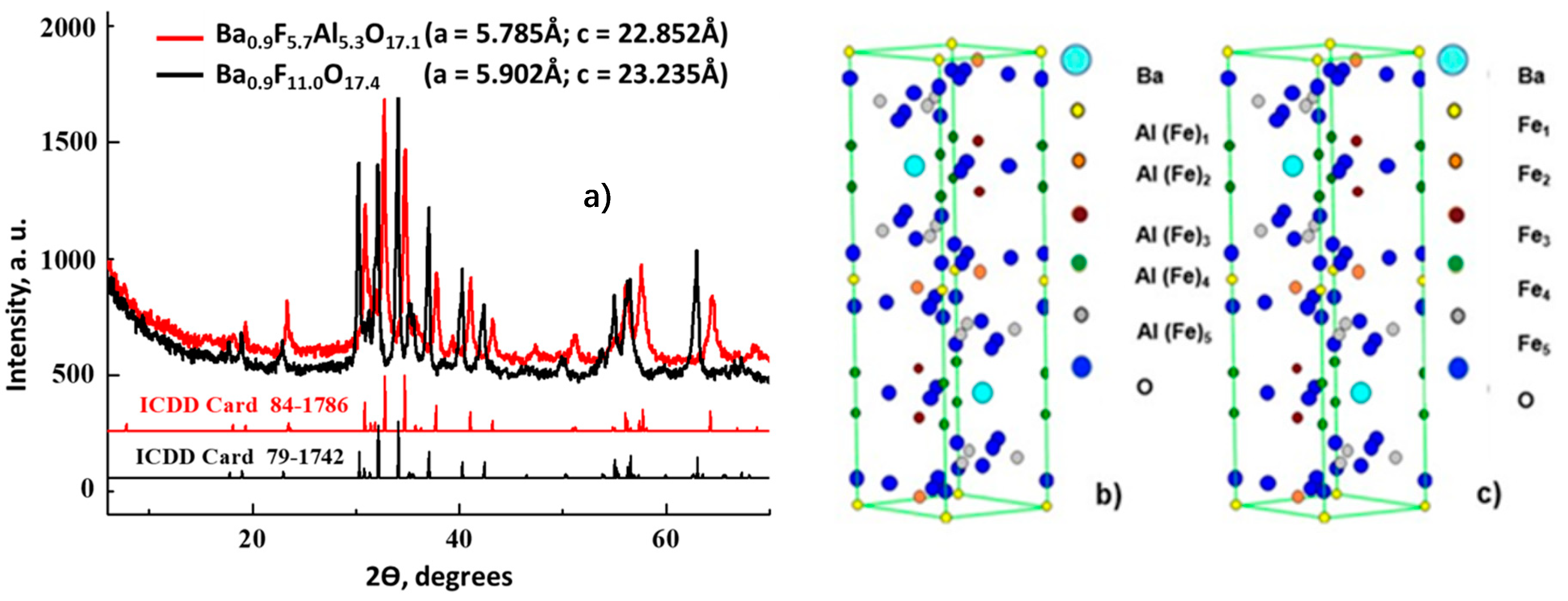
According to X-Ray diffraction (XRD) patterns (Figure 1), both as-synthesized Fe-substituted Ba-hexaaluminates with degree of Al3+ to Fe3+ exchange in hexagonal structure of 60% and 100% consisted of alternatively stacked spinel blocks of closed packed oxide ions and mirror planes [41]. The XRD patterns shown in Figure 1a correspond to the reported structure of Fe-substituted Ba-hexaaluminates [50,52,53,54]. Our BaFeHAl material has a β-alumina type framework [50] of hexagonal symmetry (ICDD card 84-1786) with lattice parameters a = 5.785 Å; c = 22.852 Å similar to the structure of BaFe12O19 [55]. The crystollagraphic positions of XRD reflections recorded with our BaFeHF material corresponded to the same structure were shifted to lower angles. This is a result of asymmetric widening of the hexagonal unit cell (a = b = 5.902 Å; c = 23.235 Å) caused by the increased extent of Al3+ to Fe3+ substitution. The XRD patterns of BaFeHF material shown in Figure 1a are in agreement with magnetoplumbite structure displaying the unit cell parameters a and c similar to that reported in the literature [53], ICDD card 79-1742. The iron and aluminum atoms occupy the same positions in the unit cells of BaFeHAl and BaFeHF materials (Figure 1b,c) with different bonds length determined by ionic radii of corresponding ions. According to Rietveld refinement, part of iron ions’ positions in the unit cell of hexaaluminate structure BaFe12O19 [50,53,54] in our co-precipitated materials remain not occupied living cationic vacancies. Therefore, the formula of these materials followed from XRD data differs from this classical composition containing 11 (Al + Fe) atoms for BaFeHAl and 11 Fe atoms for BaFeHF with less oxygens for keeping the crystals’ electroneutrality.
Table 1 depicts the chemical compositions and texture parameters of BaFeHAl and BaFeHF tested in RWGS by chemical looping. The texture of co-precipitated (CP) and carbon-templated (CT) materials.
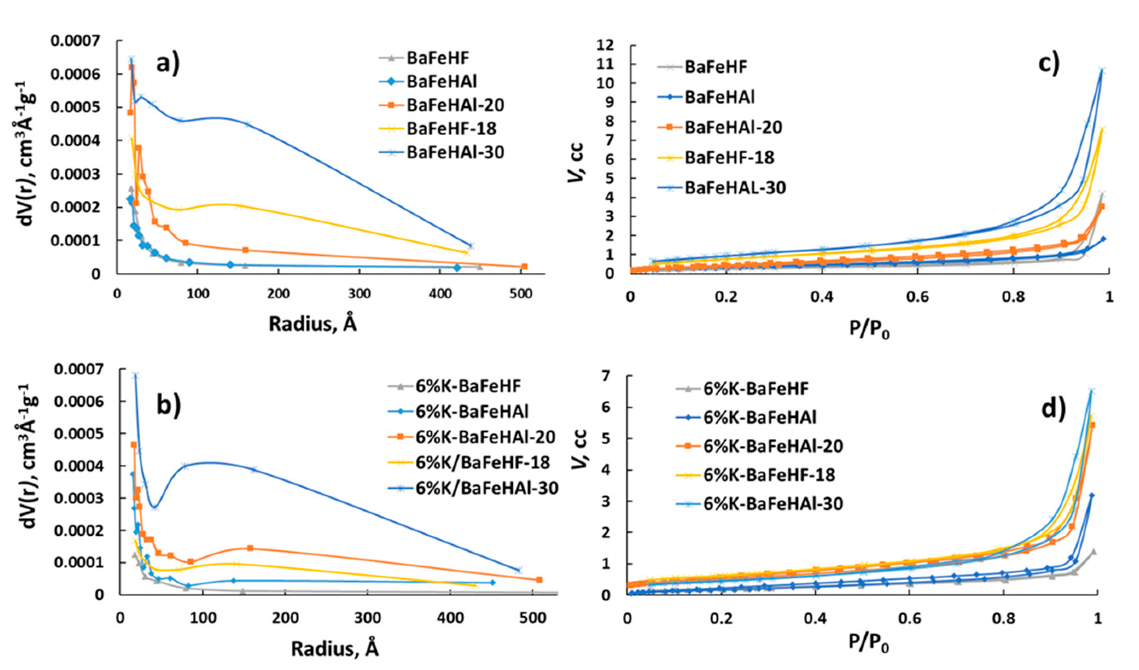
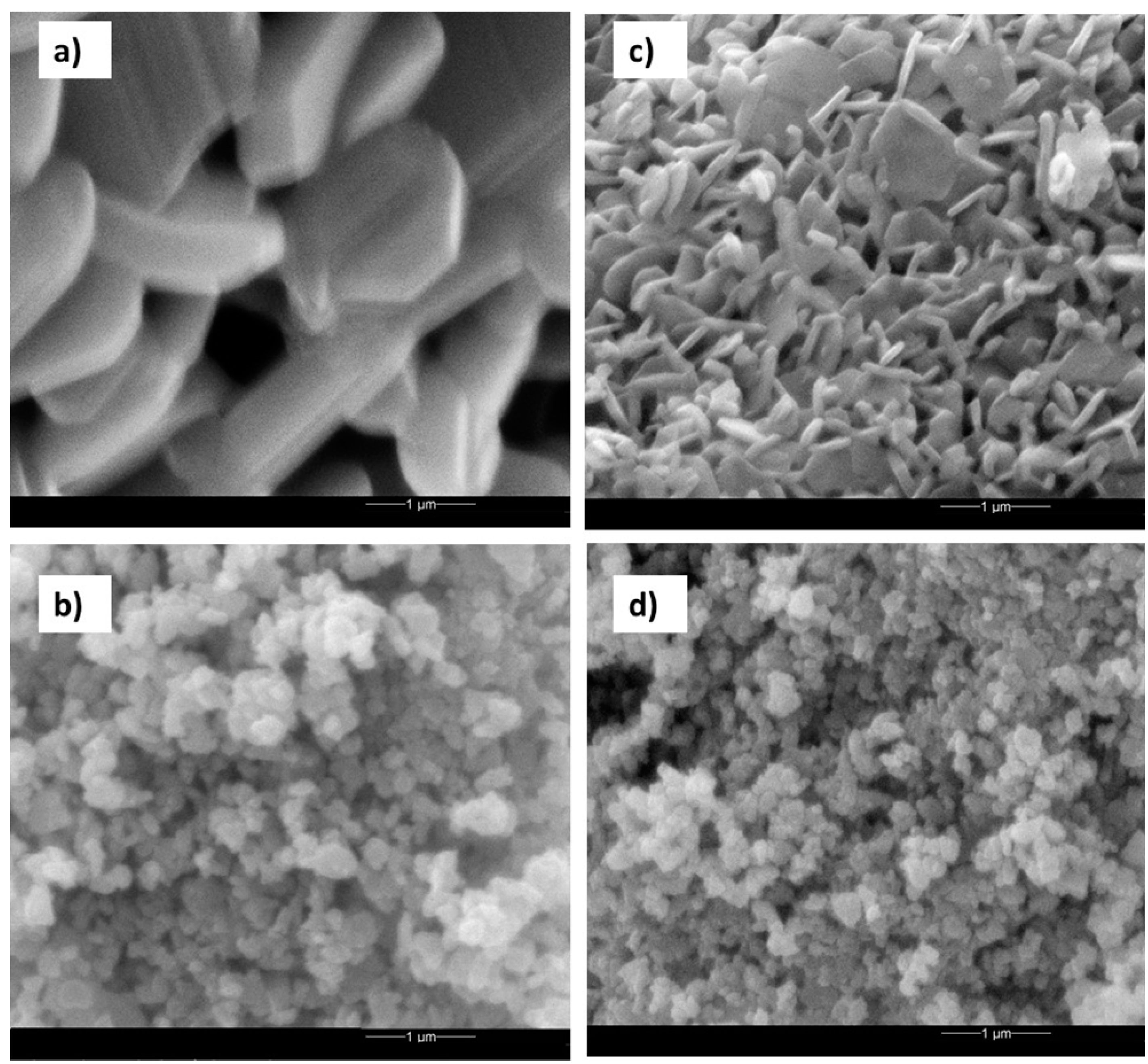
With 60% and 100% degree of Al3+ to Fe3+ exchange, it was also characterized after modification with potassium (6% wt) and after High Energy Ball Milling (HEM). Carbon-templating and HEM increased the surface area of BaFeHAl material from 5 m2 g−1 to 20 and 30 m2 g−1, respectively, without change of phase and chemical composition. In the case of BaFeHF application of HEM, the surface area increased from 2 m2 g−1 to 18 m2 g−1 with no change in structure and composition. Carbon templating decreases the platelets size of primary nanocrystals of BaFeHAl from 0.3–0.7 (co-precipitation) to 0.1–0.4 µm forming additional mesopores between nanocrystals aggregates [50]. This is reflected by the appearance of small mesopores with radius of <70 Å (Figure 2b). The HEM treatment further decreased the size of co- precipitated BaFeHAl primary crystals due to grinding to 0.03–0.1 µm (Figure 3c,d), strongly increasing the pore volume at wide range of pore radii (Figure 2).
Similar effect was observed after HEM treatment of BaFeHF (Figure 2 and Figure 3a,b). HEM treatment decreased the average crystal size of both co-precipitated BaFeHAl and BaFeHF materials to the level detectable from the widening of XRD reflections, 30 and 40 nm, respectively. Promotion with potassium decreased the surface area of all materials due to aggregation of primary crystals to less porous agglomerates [50]. This brings the increase of pore diameter due to the predominant disappearance of small pores (Figure 2a,c).
2.2. Factors Affecting the Performance of Fe-Substituted Ba-Hexaaluminates
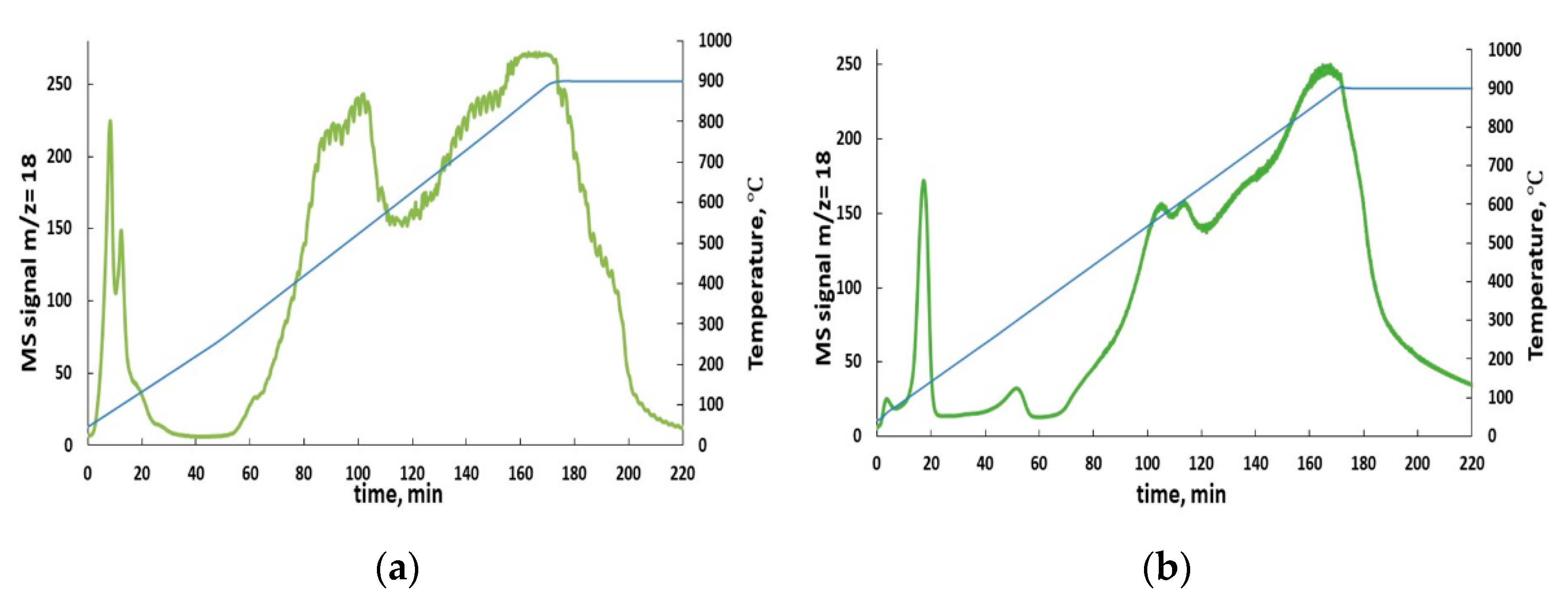
RWGS includes two consecutive steps: H2-reduction and CO2 oxidation of catalyst at elevated temperatures, where thermal stability of the structure of selected phases is critical for testing their performance. The BaFeHAl and BaFeHF materials are very stable at oxidative conditions being prepared by annealing at temperatures of >1000 °C. However, they may decompose into different phases in reductive H2-atmosphere [49]. The spectra of water evolution during Temperature Programmed Reduction (TPR) of as-prepared BaFe-hexaxaluminate and BaFe-hexaferrite are shown in Figure 4. After low-temperature peaks corresponding to removal of adsorbed water, the spectra contain groups of high-temperature peaks corresponding to water evolution due to H2-reduction of corresponding bulk phases. BaFeHAl is more stable to reduction compared with BaFeHF: high-temperature water evolution starts at 450 and 300 °C, respectively. In addition, the intensity of low-temperature reduction peak centered at ~400 °C in case of BaFeHF is significantly higher compared with that for BaFeHAl centered at 550 °C. This may be a result of deep deoxygenation of the structure of both materials in hydrogen atmosphere at temperatures >300–350 °C for BaFeHF and >450–550 °C for BaFeHAl, and their conversion to other oxygen-depleted phases. The phase compositions of as-prepared BaFeHAl and BaFeHF catalysts after treatment in 10% H2-Ar flow in a tubular reactor at 35 cm3 min−1gram−1 for 20 min are shown in Table 2. From these data it follows that at H2-reduction step of RWGS-CL cycle the BaFeHAl phase is stable up to 450 °C and the BaFeHF phase up to 350 °C.
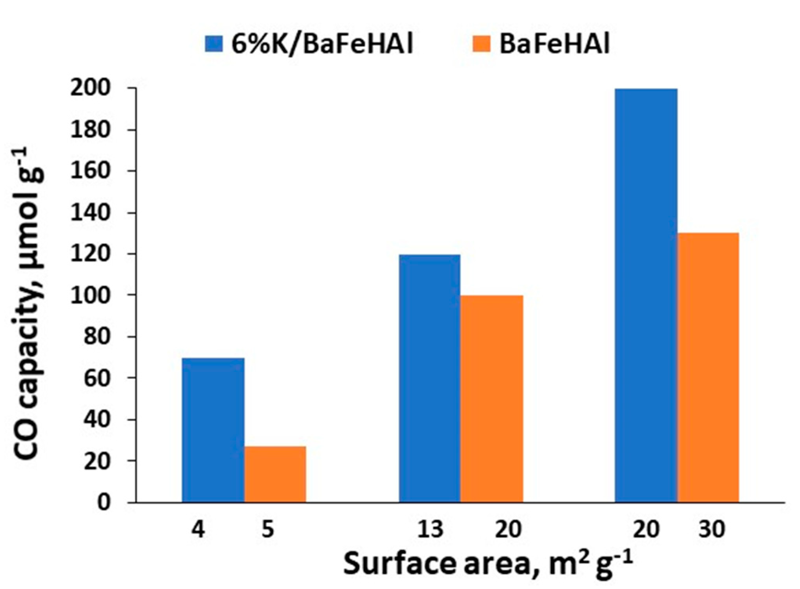
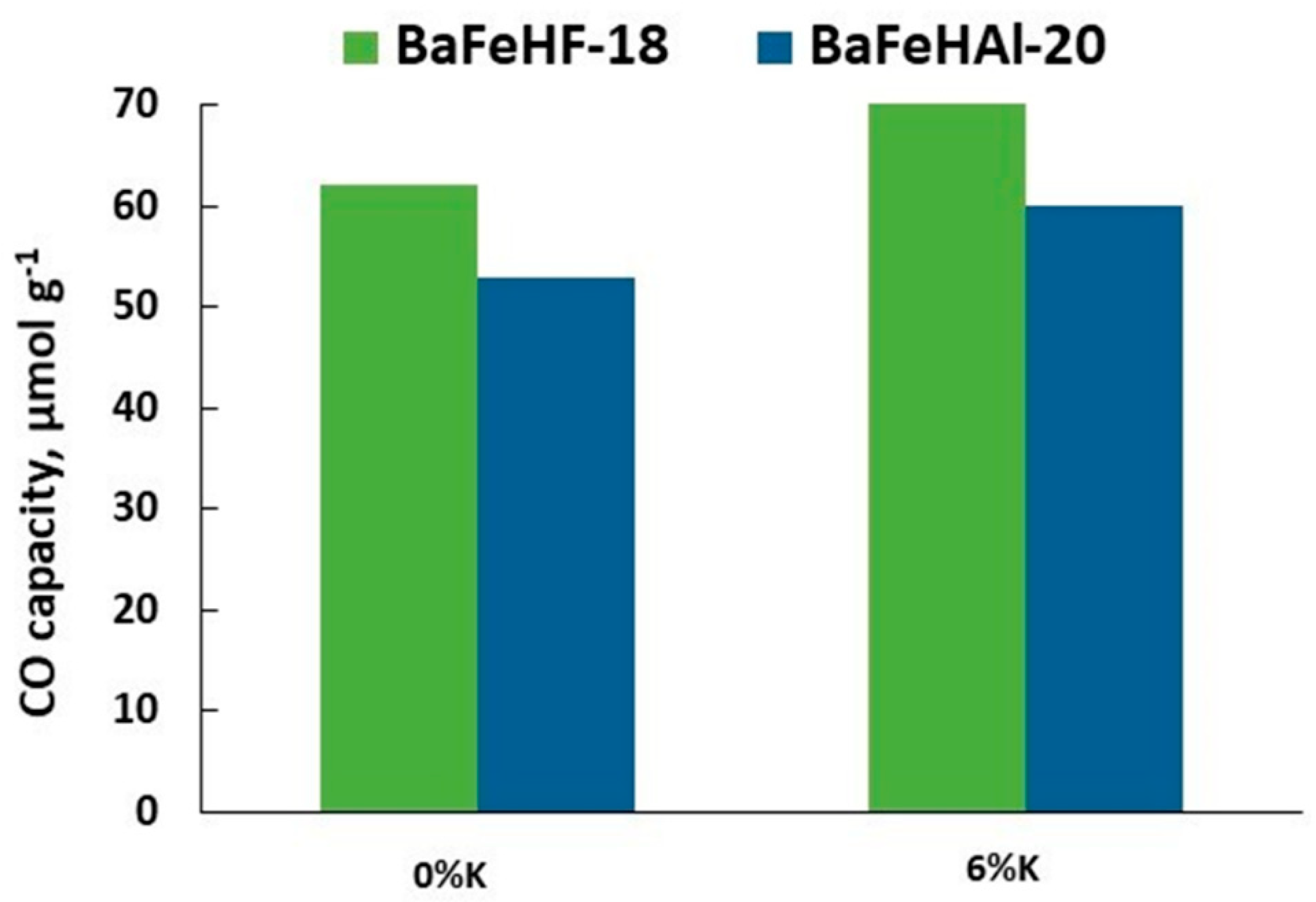
The results of RWGS-CL presented in Figure 5 show that the CO capacity of this material increases proportionally to its surface area both in as-prepared and K-promoted forms. K-promoted BaFeHAl displayed significantly higher CO capacity compared with as-prepared material in spite of lower surface area. Specific CO capacity (SC) of K-promoted catalysts normalized to the unit of surface area (µmol m−2) increased by a factor of 1.8–3.2. This effect is related to higher concentration of oxygen vacancies in reduced Fe-materials due to reductive action of potassium [50,56]. The efficiency of BaFeHAl and BaFeHF catalysts with similar surface areas was compared in isothermal RWGS-CL runs at 350 °C. Data presented in Figure 6 show that BaFeHF display higher CO capacity, and thus is more efficient than BaFeHAl. The SC is 3.5 and 2.6 µmol m−2 for BaFeHF and BaFeHAl, respectively. The ratio SCBaFeHF/SCBaFeHAl is close to the ratio of iron content in these materials (Table 1), reflecting that the active sites for RWGS reaction are anionic vacancies formed at the catalysts surface at H2-reduction step due to the conversion of Fe3+ to Fe2+ [50,56]. Their surface concentration should be proportional to the iron content taking in account the similar structure of both materials. Promoting BaFeHF with K increased its CO capacity (Figure 6) and SC value to 8.7 µmol m−2.
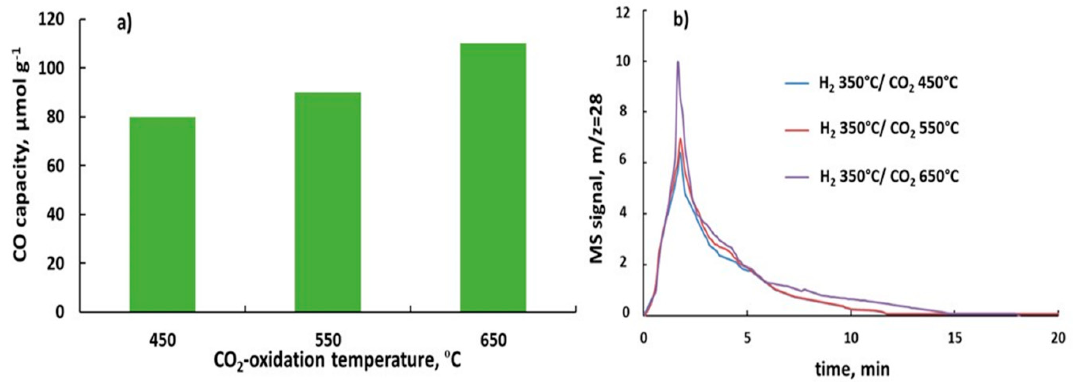
Increasing of H2-reduction temperature (Tr) of BaFeHF catalyst beyond 350 °C leads to decomposition of this phase converting it to iron oxides, barium oxide, and carbonate (Table 2). Ba-compounds are not active in the redox cycle. Presented in Figure 7 are the results of non-isothermal testing of 6%KBaFeHF-18 keeping the reduction temperature at 350 °C that avoids catalysts reductive decomposition. Increasing CO2 oxidation temperature increased CO capacity from 68 (Figure 6) to 114 (µmol g−1) (Figure 7a), depicted by the shape of CO production peaks (Figure 7b). XRD analysis indicates that the structure of 6%K/BaFeHF did not change after the CO2 oxidation step at 550–650 °C. It means that increasing oxidation temperature involves additional Fe2+ ions with lower oxidation ability to the CO2 oxidation process.
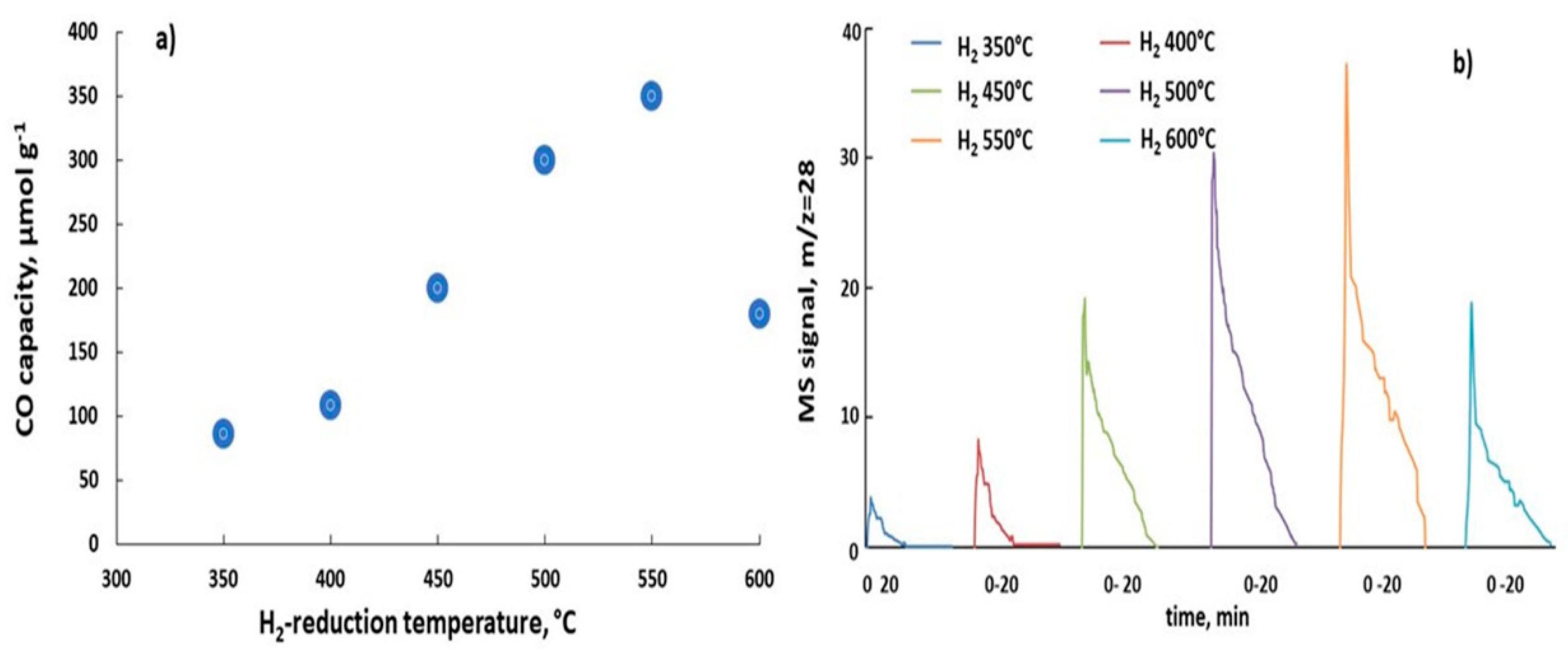
The decomposition of BaFeHAl catalyst during H2-reduction step of the RWGS-CL cycle at temperatures of >450 °C yields novel thermostable BaFeHFr phase as a main component with the depletion of BaCO3, Al2O3, and Fe3O4 phases (Table 2). Since BaFeHF is a more efficient catalyst, the effect of reduction temperature on CO capacity of 6%K/BaFeHAl was studied at the temperature range of 350–600 °C where the catalyst contained BaFeHAl or BaFeHFr phases, keeping constant the CO2 oxidation temperature at 450 °C. The results of this non-isothermal testing series are shown in Figure 8.
The CO capacity of K-promoted BaFeHAl reached a maximum at 550 °C, increasing by a factor of 1.75 compared to the value at 450 °C (Figure 8a). This is illustrated by changes of the shape of CO production peaks recorded at 450 °C in CO2 oxidation step (Figure 8b). No changes of catalysts phase composition were detected by XRD after CO2 oxidation step.
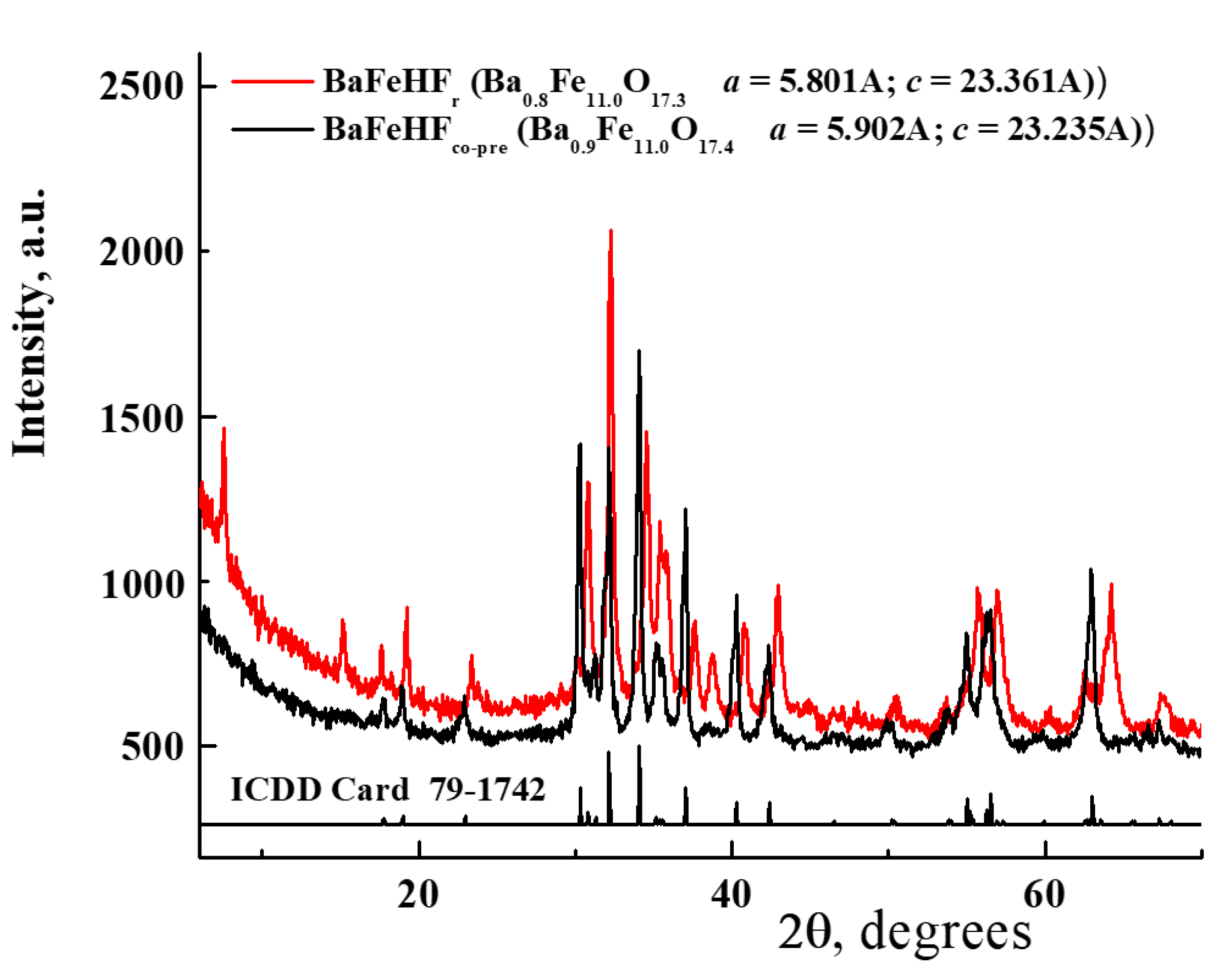
The results are evident for two effects: one is the improved thermal stability of BaFeHFr obtained from BaFeHAl compared with direct co-precipitation, and the other is activation of 6%K/BaFeHAl. The latter is related to the formation of BaFeHFr phase with a higher activity. BaCO3 and Al2O3 cannot participate in redox cycles, and Fe3O4 formed together with BaFeHFr (Table 2) has low activity in RWGS-CL [12] and its content is small. The 6%K/BaFeHAl was characterized by XRD, N2-adsorption, and XPS after reduction at different temperatures. Figure 9 compares the XRD patterns of 6%K/BaFeHF obtained by co-precipitation with the XRD patterns of BaFeHF component of 6%K/BaFeHAl reduced at 550 °C. The latter was derived from the experimental XRD data by deconvolution using Rietveld program that separates reflections related to BaFeHF phase from that characteristic of BaCO3 and Al2O3. The XRD patterns of BaFeHFr after reduction of 6%K/BaFeHAl at 500, 550, and 600 °C (Table 2) were identical.
Comparison of XRD patterns of BaFeHF phases obtained by co-precipitation and reduction of BaFeHAl (Figure 9) shows significant differences although both structures relate to the same space group P63/mmc (194). BaFeHFr displays two reflections at low angles of 2θ = 7.6 and 15.2° corresponding to planes (002) and (004), respectively, not found in BaFeHF. The relative intensities of XRD peaks are significantly different. In the triad of most intensive peaks corresponding to planes (110), (107), and (114), the relation between intensities is I110/I107/I114 = 50/90/100 for 6%K/BaFeHF and 40/100/65 for BaFeHFr. In addition, the XRD reflections related to BaFeHFr are shifted to higher angles compared with BaFeHF. This yields significant changes of the unit cell parameters from a = 5.902 Å, c = 23.235 Å (BaFeHF) to a = 5.801 Å, c = 23.361 Å (BaFeHFr).
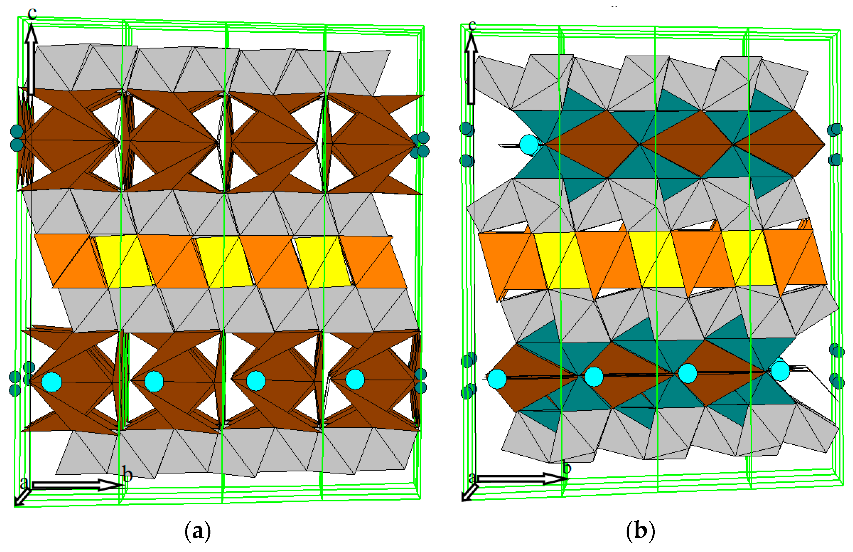
Analysis of these variances of XRD patterns using Rietveld method showed that the atomic distributions in the unit cells of BaFeHF and BaFeHFr are also different (Tables S1 and S2). Though the nomenclature of atoms and their positions in the structure is similar in both cases, the coordinates of all atoms, besides Ba and Fe1, are meaningfully dissimilar, as may be clearly seen along the c axis (Z coordinates). This explains the appearance of reflections (002) and (004) for BaFeHFr. The differences of intensities of XRD patterns between BaFeHFco-pre. and BaFeHFr is mainly a result of shifting atomic positions in the hexaferrite structure. Presented in Figure 10 are the oxygen environments of Fe atoms in the framework of both materials. The color of tetrahedra and octahedra corresponds to the color of the groups of Fe atoms in the unit cell as denoted in Figure 1b,c. In both structures the Ba atoms are located at the main points of the lattice symmetry P63/m (ZBa = 1/4 and 3/4). This means that Ba atoms are the force centers of stability for this type of crystals. In case of BaFeHFco-pre. (Figure 10a) the yellow-orange zone in the unit cell center between Ba atoms is represented by yellow octahedra including two atoms Fe1 and orange tetrahedra including four atoms Fe2. Located at the top and bottom of this zone are zones of gray octahedra including six atoms Fe5 in each gray zone. Bonding between Ba-atoms and Fe-atoms belonging to the gray zones occurs through brown octahedra including Fe3 atoms (two atoms at every side). The two atoms Fe4 denoted by green color are located in Ba-plane m with small deviation from Z axis at half occupancy. These atoms do not have bulk oxygen environment. The character of oxygen environment of Fe atoms in the lattice of BaFeHFr is identical to that in BaFeHFco-pre. (Figure 10b). However, due to shifting of atomic positions in the compressed lattice, the octahedral-tetrahedral oxygen environment in yellow-orange and gray zones is distorted with their expansion along c axis. The most important difference is a significant shift of the positions of green Fe4 atoms along c axis relative to the plane m of Ba-atoms located perpendicular to the c axis at distances of ¼ and ¾ from the origin. This may be clearly seen in Figure 10 according to positions of green spheres representing Fe4 atoms in unit cells. Due to this shift near these Fe4 atoms, the bulk oxygen surrounding appears evident for the formation of additional Ba–O–Fe bridges in the structure of BaFeHFr, reinforcing the connection between alternatively stacked spinel blocks. This may explain the higher thermostability of BaFeHFr phase formed by reductive decomposition of BaFeHAl compared with that obtained by co-precipitation. The original valence state of iron ions substituting Al3+ ions in hexaaluminate structure is Fe3+. Therefore, the concentration of anionic vacancies originated from reduction of these ions at the catalyst surface to Fe2+ is proportional to the ratio of Fe2+/Fe3+ that may be measured by XPS.
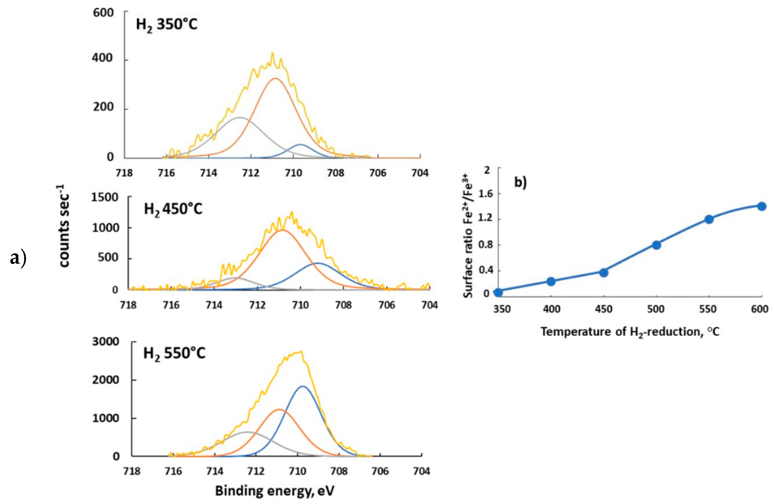
Shown in Figure 11 are the XPS spectra of the material 6%K/BaFeHAl reduced at 350–550 °C. The existence of iron ions at different valence state and environment follows from deconvolution of Fe2p3/2, core spectra in three signals. Peaks at lowest energy of 709.3–710.0 eV reflect the existence of Fe2+ ions in the surface layer [50]. The Fe3+ ions at different oxygen environment in the hexaaluminate lattice are represented in XPS spectra by peaks of higher BE of 710.4–711.6 and 712–714 eV [50]. The values of surface Fe2+/Fe3+ ions ratio were calculated based on their surface concentrations derived from deconvoluted XPS spectra. They are shown in Figure 11b as a function of reduction temperature of 6%BaFeHAl catalyst. The rate of increase of Fe2+/Fe3+ ratio in the range 450–600 °C (9.0 × 10⁻³ °C−1) is about three times higher than at 350–450 °C (3.5 × 10⁻³ °C−1), corresponding to deeper reduction of iron in 6%K/BaFeHAl. This may be attributed to higher reducibility of Fe3+ ions at the surface of BaFeHF phase, yielding more Fe2+ ions related with oxygen vacancies that play a role of active sites at the CO2 oxidation step.
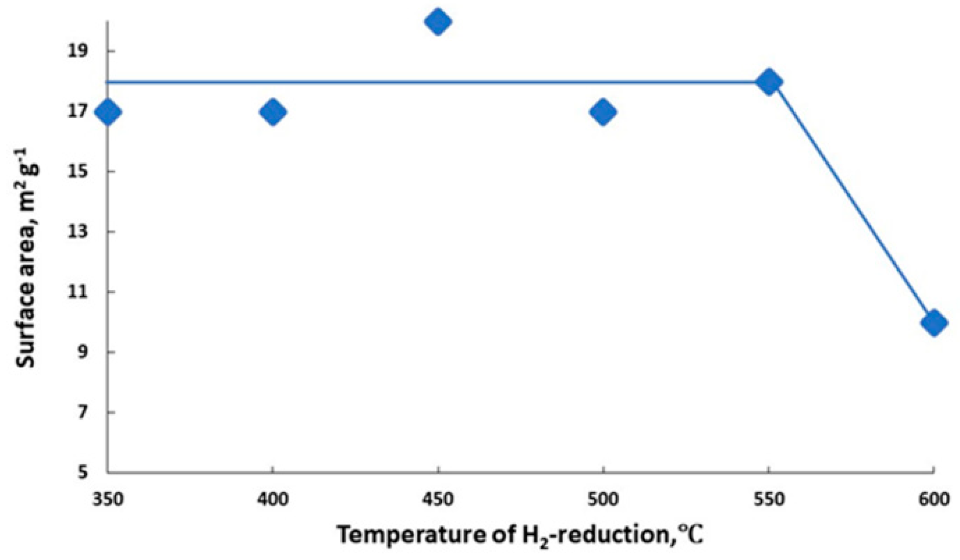
Since the surface area of reduced 6%K/BaFeHAl catalyst remains about the same at the range of 350–550 °C (Figure 12), the CO capacity of 6%K/BaFeHAl catalyst strongly increased at 500–550 °C after complete reductive transformation of BaFeHAl phase to BaFeHFr. Further increase of the reduction temperature to 600 °C did not change the phase composition of the catalyst (Table 2) and crystal size of BaFeHFr, BaCO3, Al2O3, and Fe3O4 phases. However, the distortion of nanocrystals aggregates at this temperature reduced the pore volume and decreased the surface area by a factor of ~2 (Figure 12) that caused catalyst deactivation (Figure 8).
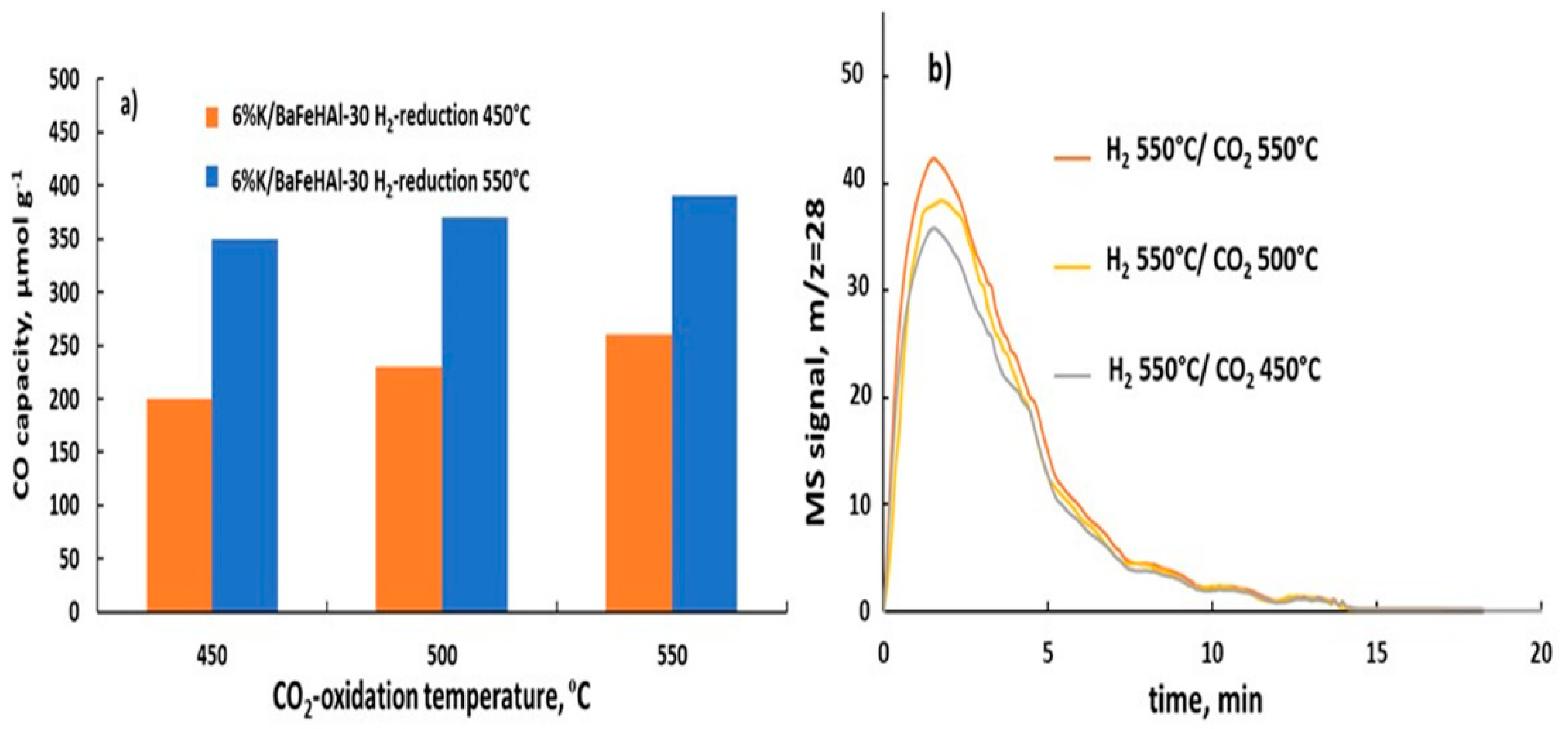
Reducing 6%K/baFeHAl-30 at 550 °C increased CO capacity (Figure 8a). Thus, this catalyst was tested at this reduction temperature and oxidation temperature range of 450–550 °C where the material is resistant to sintering. CO capacity depicted in Figure 13a, based on data in Figure 13b, indicate that with increasing of oxidation temperature, the CO capacity increased from 350 to 400 (µmol/g) (Tr = 550 °C) and from 208 to 248 (µmol g−1) at Tr = 450 °C. According to XRD and N2-adsorption data, the structure, phase composition, and crystals size of 6%K/BaFeHAl-30 reduced at 550 °C did not change after these experiments. Therefore, the amount of available active sites (oxygen vacancies) controlled by the reduction did not change during oxidation, indicating that higher oxidation temperature involves additional Fe2+ ions with lower oxidation ability.
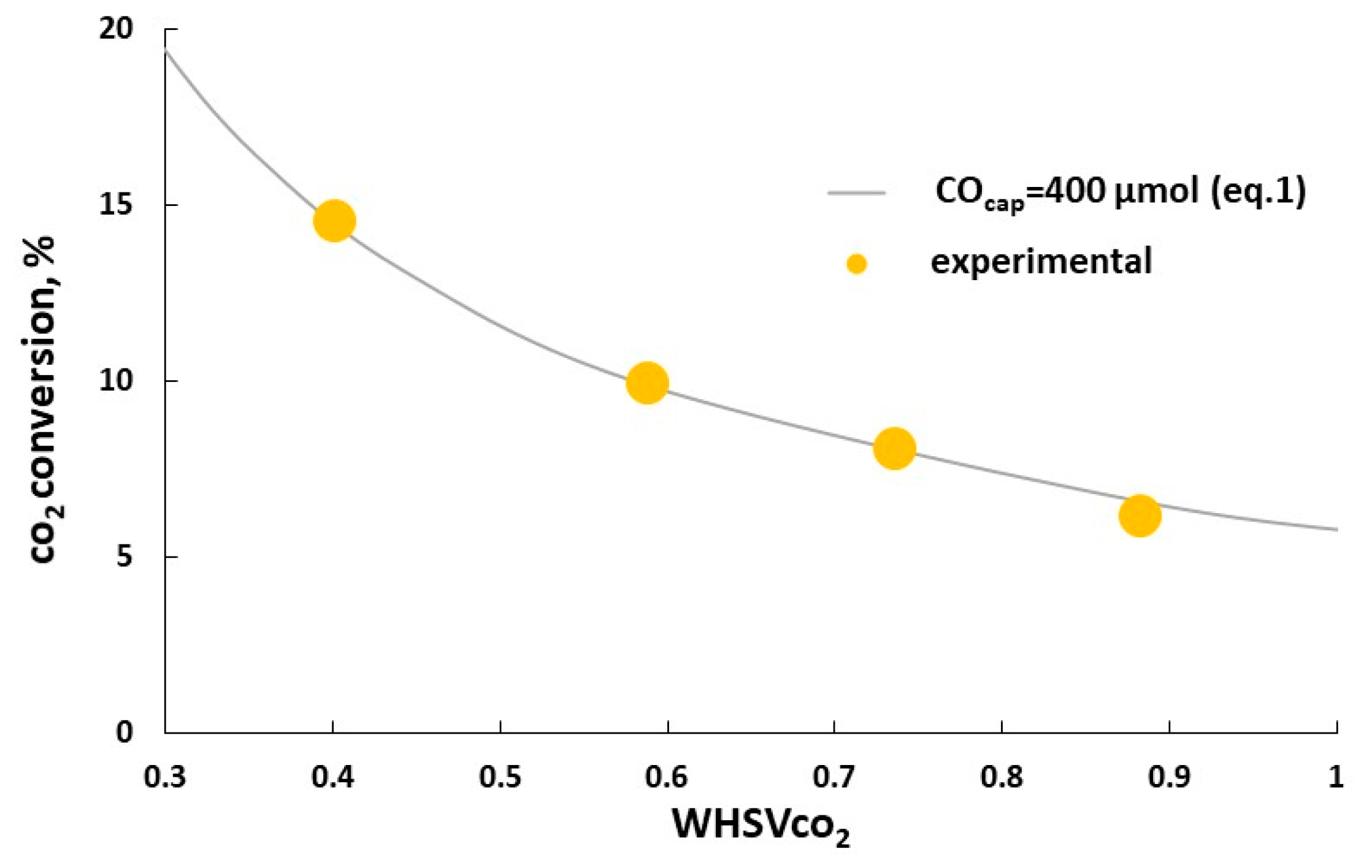
At fixed CO2 concentration in the inlet gas at the CO2 oxidation step of RWGS-CL cycle, the catalysts CO2 capacity is connected with CO2 conversion at given weight hour space velocity of CO2 (WHSVCO2) according to Equation (1). This equation describes well the CO2 conversions calculated according to evolved CO amounts measured at WHSVCO2 of 0.4–0.9 h−1 with 6%K/BaFeHAl-30 catalyst at optimal isothermal RWGS-CL conditions. These data fit well to the CO2 conversions calculated according to Equation (1) assuming the constant CO capacity of 400 µmol g−1 (Figure 14). The maximal CO2 conversion of 14.9% was obtained at lowest tested WHSVCO2 = 0.4 h−1. For further increase of CO2 conversion, the CO capacity of BaFe-hexaaluminate catalyst should be improved more. The reported data assume that this challenge may be achieved by improvement of hexaaluminate catalyst—further increasing the materials surface area and application of K-promoted high-temperature modification of BaFeHF as a pure phase not diluted with Fe-, Al-oxides, and Ba-carbonate.
3. Materials and Methods
3.1. Catalysts Preparation
A series of Ba-Fe-hexaaluminates with Fe to Al exchange degree of 60% denoted as BaFeHAl was prepared by hot co-precipitation strategy as described in [52,53]. The solution of Ba(NO3)2 (Alfa Aesar, Yehud, Israel) and Fe(NO3)3·9H2O (Fisher Chemicals, Yehud, Israel) in hot distilled water after addition of Al(NO3)3·9H2O (Riedel de Haën, Or Yehuda, Israel) was acidified to pH~1 with diluted HNO3 (Gadot, Netanya, Israel). This solution was poured under vigorous stirring in excess of (NH4)2CO3 solution heated at 60 °C. The mixed hydroxides were precipitated at pH 7.5–8.0. After aging of obtained slurry at 60 °C for 3 h, filtering, washing with distilled water and in air at 110 °C overnight, the material was calcined in air at 450 °C for 2 h with heating rate of 2 °C min−1. Finally, the catalyst was calcined in air at 1200 °C for 3h with heating rate of 2 °C min−1. Potassium was deposited at the calcined catalyst by incipient wetness impregnation with aqueous solution of K2CO3 (the K2CO3 solution of suitable concentration was added to the catalyst powder at an amount corresponding to the water capacity of the material leaving the material dry) with overnight drying at 110 °C and ending calcination at 450 °C.
The preparation of 100% substituted BaFe-hexaaluminate (hexaferrite—HF) with formula Ba0.82 Fe10.74O18.1 was conducted by regular hot co-precipitation strategy using a different calcination procedure [53]. The dried samples were ground and then calcined by intermediate steps at 500, 700, 900, 1000, 1100, and 1200 °C (heating rate, 2 °C min−1; hold at each step, 10 h). This series was denoted as BaFeHF. Then a series of HF catalysts containing 6%K was prepared by incipient wetness, called 6%K/BaFeHF.
The BaFe-hexaaluminate catalysts with increased surface area and substitution of Al with 60% iron was prepared by carbon templating (CT) [46,47]. A hot (60 °C) acidic aqueous solution of Ba-Fe-Al-nitrates was added under vigorous stirring to the carbon black (Alfa Aesar, Yehud, Israel, 75 m2 g−1, bulk density 80–120 g L−1) previously hydrophilized by treatment with nitric acid. The amounts of solution and carbon black were selected to yield 45 wt% Ba-Fe-hexaaluminate (calculated as sum of oxides) and 55 wt% carbon in the dried precipitate. A large excess of aqueous (NH4)2CO3 solution heated to 60 °C was poured to the obtained slurry heated to 60 °C under vigorous stirring. Then the slurry was aged for 3 h, filtered, washed and dried by freeze-drying method (Instrument Christ Beta 1–8) for 72 h. The dried precursors were calcined in air at 450 °C for 2 h (2 °C min−1) and then at 1000 °C (2 °C min−1) for 8 h. The catalyst was designated as BaFeHAl-20. A K-promoted catalyst was then prepared by deposition of 6 wt% potassium as described above to this CT material designated as 6%K/BaFe-HAl-20.
The carbon templating (CT) strategy [46,47] was applied for preparation of BaFeHAl material with Fe-substitution degree of 60% and increased surface area. The carbon black (Alfa Aesar, Yehud, Israel 75 m2 g−1, bulk density 80–120 g L−1) hydrophilized by treatment with nitric acid at an amount corresponding to the 55 wt% in dried precipitate was added under vigorous stirring to a hot (60 °C) acidified (pH = 1) aqueous solution of Ba-Fe-Al-nitrates. An excess of aqueous solution of ammonium carbonate was poured under stirring to the obtained slurry at 60 °C. After aging of obtained slurry at 60 °C for 3 h, filtering, washing with distilled water and freeze-drying (Instrument Christ Beta 1–8) for 72 h, the material was calcined in air at 450 °C for 2 h with heating rate of 2 °C min−1. Finally, the catalyst was calcined in air at 1000 °C for 8h with heating rate of 2 °C min−1. The CT-catalyst was designated as BaFeHAl-20. Potassium was deposited at the calcined catalyst by incipient wetness impregnation with aqueous solution of K2CO3 with overnight drying at 110 °C and ending calcination at 450 °C. This CT-catalyst was designated as 6%K/BaFeHAl-20.
3.2. Catalysts Characterization
The N2 adsorption-desorption isotherms were recorded for all catalysts after outgassing under vacuum at 250 °C for 2 h using NOVA 3200e (Quantachrome, Anton Paar QuantaTec Inc., Boynton Beach, Florida, USA) instrument. The surface area, pore size, and volume of the catalysts were calculated from these isotherms using conventional BET (Brunauer-Emmett-Teller) [57] and BJH (Barrett-Joyner-Halenda) [58] methods. The catalysts chemical composition was measured by EDS (Energy Dispersive Spectroscopy) method using Quanta-200, SEM-EDAX (FEI Co., Hillsboro, OR, USA) instrument. The Panalytical Empyrean Powder Diffractometer (Cambridge, UK) equipped with position-sensitive detector X’Celerator fitted with a graphite monochromator, at 40 kV and 30 mA, was used for collecting of catalysts XRD patterns. They were analyzed with software developed by Crystal Logic Inc. (Los Angeles, CA, USA). The SBDE ZDS computer search/match program coupled with the ICDD database was used for phases identification. The Rietveld refinement of the XRD profile implementing the DBWS-9807 program (Atlanta, GA, USA) was applied for calculating of phases content in catalytic materials.
The SEM images of catalytic materials were recorded using Quanta-200, SEM-EDAX, FEI Co. instrument (Hillsboro, OR, USA). TPR measurements were performed using Chemisorption Analyzer Autochem II 2920 instrument (Micrometrics Norcross, Georgia, USA) equipped with TCD detector. TPR was done in 10%H2/Ar flow of 5 mL min−1. The X-ray photoelectron spectrometer ESCALAB 250 apparatus (Hamamatsu City, Japan) working at ultrahigh vacuum (1 × 10⁻⁹ bar) with an Al Kα X-ray source and a monochromator was applied for collecting of XPS spectra. Fitting a sum of the single component lines to the experimental data by means of a non-linear least-square curve was used for identification of the spectral components of Fe signals. EX05 argon gun system performed controlled removal of surface layers. Cleaning the surface from adsorbed species before recording the XPS spectra was done using the EX05 argon gun system.
3.3. Catalysts Testing
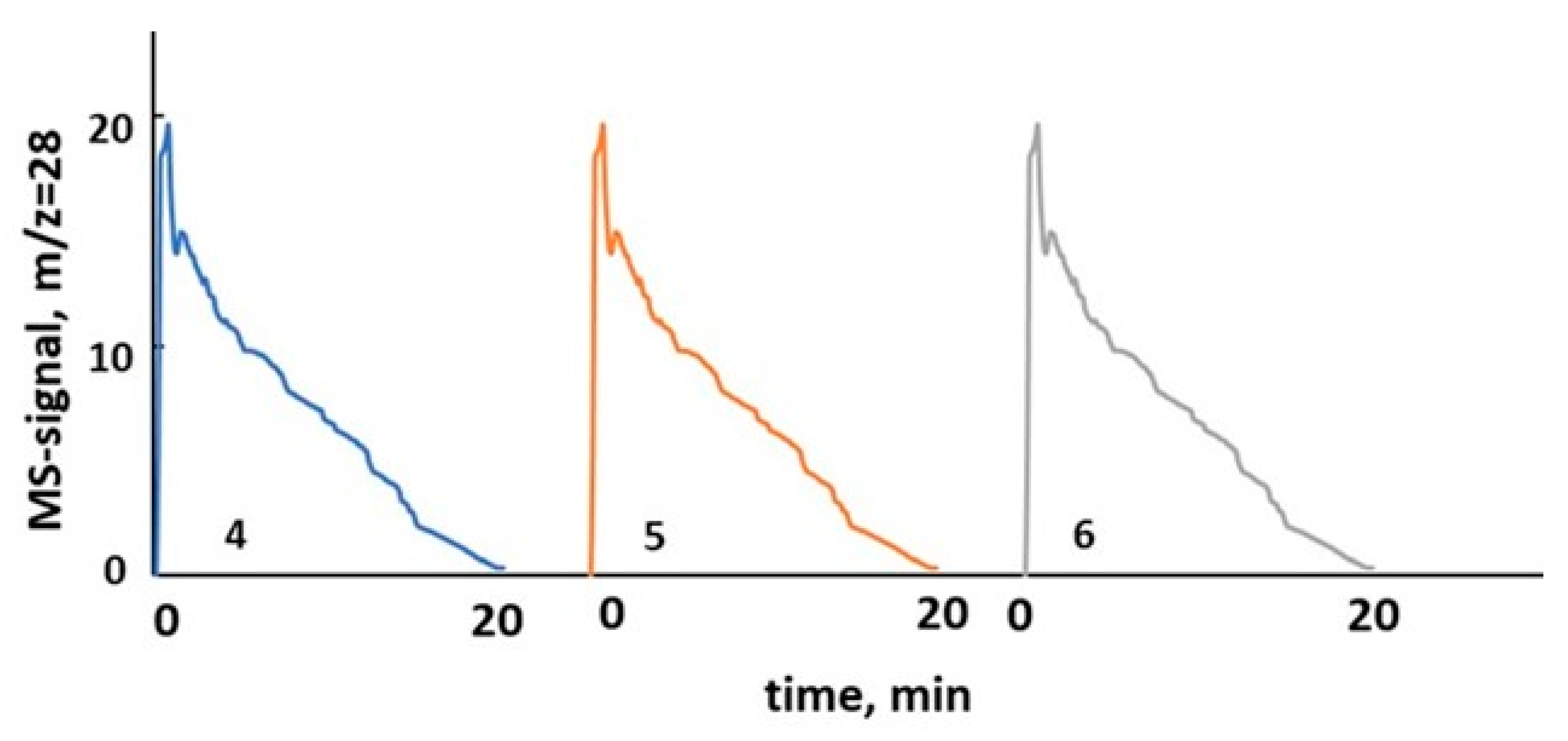
The reduction-oxidation steps of CO2 conversion experiments were conducted in a quartz U-tube reactor at catalyst loadings of 0.10–0.22 g using a Chemisorption Analyzer AutoChem II 2920 instrument Norcross, Georgia, USA, Micrometrics Co. equipped with mass spectrometer Cirrus 2, MKS detector. The catalyst powder (fraction 25–180 µm) was fixed at the isothermal section of the reactor between glass-wool plugs. The inlet CO2 concentration at oxidation steps in all testing experiments was 5% vol. The detected CO MS signals (m/z = 28) intensities were calibrated with CO/He mixtures of corresponding varied compositions. The RWGS-CL cycles were conducted at different temperatures in the range of 350–600 °C. The sample was first reduced in 10%H2/Ar flow of 15 mL min−1 for 20 min. This step was followed by a 20 min He flushing (50 mL min−1) and then a catalyst oxidation step (CO2 reduction to CO) was carried out in 5% CO2/He flow of 15 mL min−1 for 20 min. The system was flushed with He again for 20 min, and the cycle was repeated. First, the catalyst was stabilized in three consecutive redox cycles followed by additional three cycles of stable operation. CO peaks recorded in RWGS-CL isothermal cycles # 4–6 at 450 °C with 6%K/BaFeHAl catalyst are shown in Figure 15.
The catalysts performance was characterized by two parameters: CO capacity (COcap.), and CO2 conversion (XCO2). Integration of calibrated CO peaks areas recorded in the oxidation step of the cycle yielded amount of µmols of CO/g.cat, denoted as catalysts CO capacity at selected testing conditions. The average CO2 conversion corresponding to the oxidation part of the RWGS-CL cycler was calculated according to Equation (1):
where, MCO—amount of CO formed during oxidation step of the RWGS-CL cycle (mmol), MCO2—amount of CO2 fed to reactor during oxidation step of the cycle (mmol), WHSVCO2 (g CO2 gcat−1 h−1), t0—the length of the CO2-oxidation cycle (h).
XCO2 = MCO/MCO2·100% = COcap.·MWCO2 (WHSVCO2·t0·1000)−1·100%
4. Conclusions
The Fe-substituted Ba-hexaaluminates are active catalysts for RWGS reaction conducted in chemical looping mode. Increasing of the degree of substitution of Al3+ for Fe3+ ions in co-precipitated Ba-hexaaluminate from 60% to 100%, increased its surface area, and promotion with potassium increased the CO capacity in isothermal RWGS-CL runs at temperatures 350–450 °C where the hexaaluminate structure is stable. At higher temperatures, the fully Fe-substituted hexaaluminate—6%K/Ba-hexaferrite—undergo reductive decomposition at the H2-reduction step of RWGS-CL cycle, yielding Fe-oxides, Ba-oxide, and Ba-carbonate. However, the partially Fe-substituted 6%K/BaFe-hexaaluminate after H2-reduction at >450 °C is transformed to a thermally stable modification of Ba-hexaferrite that contains additional Ba-O-Fe bridges in its structure, reinforcing the connection between alternatively stacked spinel blocks. The structure and surface area of this modification of Ba-hexaferrite promoted with potassium are stable against H2 reduction up to 550 °C. This allows getting higher CO2 capacity in isothermal tests at higher temperatures. The stable 6%K/BaFe-hexaferrite derived from 6%K/BaFe-hexaaluminate display higher concentration of surface oxygen vacancies compared with BaFe-hexaaluminate reflected by greater Fe2+/Fe3+ ratio according to XPS. Conducting of RWGS-CL cycles in isothermal mode at 550 °C where hexaferrite structure and texture is stable, further increases the materials CO capacity. It was demonstrated the direct connection between CO capacity measured in RWGS-CL experiments and calculated CO2 conversion.
Supplementary Materials
The following are available online at https://0-www-mdpi-com.brum.beds.ac.uk/2073-4344/10/9/1082/s1, Table S1: Atomic positions, coordinates and positions occupancies in BaFeHFco-pre material: Ba0.9Fe11.0O17.4 (a = b = 5.902 Å; c = 23.235 Å), Table S2: Atomic positions, coordinates and positions occupancies in BaFeHFr material: Ba0.8Fe11.0O17.3 (a = b = 5.801 Å; c = 23.361 Å).
Author Contributions
Conceptualization, N.U., M.V.L., M.H., and A.E.; methodology, N.U., M.V.L., M.H., and A.E.; validation, N.U.; formal analysis, N.U., M.V.L., M.H., and A.E.; investigation, N.U.; data curation, M.V.L.; writing—original draft preparation, N.U.; writing—review and editing, M.V.L. and M.H.; visualization, N.U.; supervision, M.V.L. and M.H.; funding acquisition, M.H. and M.V.L. All authors have read and agreed to the published version of the manuscript.
Funding
The Israel Ministry of Science and Technology (Grant No. 3-12386) and Blechner Foundation funded this research. This work is a part of activities of the Blechner Center of Applied Catalysis and Process Development, Chemical Engineering Department, Ben-Gurion University of the Negev in Israel.
Acknowledgments
The authors are grateful to Hagay Haun and Yaniv Gelbstein for help in disintegration of catalytic materials by high energy ball milling, and to N. Froumin for the characterization of catalytic materials by XPS method.
Conflicts of Interest
The authors declare no conflict of interest.
References
- Zhu, M.; Ge, Q.; Zhu, X. Catalytic Reduction of CO2 to CO via Reverse Water Gas Shift Reaction: Recent advances in the Design of Active and Selective Supported Metal Catalysts. Trans. Tianjin Univ. 2020, 26, 172–187. [Google Scholar] [CrossRef] [Green Version]
- Nielsen, D.U.; Hu, X.-M.; Daasbjerg, K.; Skrydstrup, T. Chemically and electrochemically catalyzed conversion of CO2 to CO with follow-up utilization to value-added chemicals. Nat. Catal. 2018, 1, 244–254. [Google Scholar] [CrossRef]
- Daza, Y.A.; Kuhn, J.N. CO2 conversion by reverse water gas shift catalysis: Comparison of catalysts, mechanisms and their consequences for CO2 conversion to liquid fuel. RSC Adv. 2016, 6, 49675–49691. [Google Scholar] [CrossRef]
- Saeidi, S.; Najari, S.; Fazlollahi, F.; Nikoo, M.K.; Sefidkon, F.; Klemeš, J.J.; Baxter, L.L. Mechanisms and kinetics of CO2 hydrogenation to value-added products: A detailed review on current status and future trends. Renew. Sust. Energy Rev. 2017, 80, 1292–1311. [Google Scholar] [CrossRef]
- Kaiser, P.; Unde, R.B.; Kern, C.; Jess, A. Production of Liquid Hydrocarbons with CO2 as Carbon Source based on Reverse Water-Gas Shift and Fischer-Tropsch Synthesis. Chem. Ing. Tech. 2013, 85, 489–499. [Google Scholar] [CrossRef]
- Vázquez, F.V.; Pfeifer, P.; Lehtonen, J.; Piermartini, P.; Simell, P.; Alopaeus, V. Catalyst Screening and Kinetic Modeling for CO Production by High Pressure and Temperature Reverse Water Gas Shift for Fischer-Tropsch Applications. Ind. Eng. Chem. Res. 2017, 56, 13262–13272. [Google Scholar] [CrossRef]
- Lyngfelt, A. Oxygen Carriers for Chemical Looping Combustion—4000 h of Operational Experience. Oil Gas Sci. Technol. 2011, 66, 161–172. [Google Scholar] [CrossRef] [Green Version]
- Bayham, S.; McGiveron, O.; Tong, A.; Chung, E.; Kathe, M.; Wang, D.W.; Zeng, L.; Fan, L.S. Parametric and dynamic studies of an iron-based 25-kWth coal direct chemical looping unit using subbituminous coal. Appl. Energy 2015, 145, 354–363. [Google Scholar] [CrossRef] [Green Version]
- Tong, A.; Bayham, S.; Kathe, M.V.; Zeng, L.; Luo, S.; Fan, L.-S. Iron-based syngas chemical Looping process and coal-direct chemical looping process development at Ohio State University. Appl. Energy 2014, 113, 1836–1845. [Google Scholar] [CrossRef]
- Galvita, V.; Hempel, T.; Lorenz, H.; Rihko-Struckmann, L.K.; Sundmacher, K. Deactivation of modified iron oxide materials in the cyclic water gas shift process for CO-free hydrogen production. Ind. Eng. Chem. Res. 2008, 47, 303–310. [Google Scholar] [CrossRef]
- Datta, P.; Rihko-Struckmann, L.K.; Sundmacher, K. Influence of molybdenum on the stability of iron oxide materials for hydrogen production with cyclic water gas shift process. Mater. Chem. Phys. 2011, 129, 1089–1095. [Google Scholar] [CrossRef]
- Galvita, V.V.; Poelman, H.; Bliznuk, V.; Detavernier, C.; Marin, G.B. CeO2-Modified Fe2O3 for CO2 Utilization via Chemical Looping. Ind. Eng. Chem. Res. 2013, 52, 8416–8426. [Google Scholar] [CrossRef]
- Meledina, M.; Turner, S.; Galvita, V.V.; Poelman, H.; Marin, G.B.; Van Tendeloo, G. Local environment of Fe dopants in nanoscale Fe: CeO2−x oxygen storage material. Nanoscale 2015, 7, 3196–3204. [Google Scholar] [CrossRef] [PubMed]
- Mattisson, T.; Lyngfelt, A.; Cho, P. The use of iron oxide as an oxygen carrier in chemical-looping combustion of methane with inherent separation of CO2. Fuel 2001, 80, 1953–1962. [Google Scholar] [CrossRef]
- Galvita, V.V.; Poelman, H.; Marin, G.B. Hydrogen Production from Methane and Carbon Dioxide by Catalyst-Assisted Chemical Looping. Top. Catal. 2011, 54, 907–913. [Google Scholar] [CrossRef]
- Corbella, B.M.; Palacios, J.M. Titania-supported iron oxide as oxygen carrier for chemical-looping combustion of methane. Fuel 2004, 86, 113–122. [Google Scholar] [CrossRef]
- Rihko-Struckmann, L.K.; Datta, P.; Wenzel, M.; Sundmacher, K.; Dharanipragada, N.V.R.A.; Poelman, H.; Galvita, V.V.; Marin, G.B. Hydrogen and Carbon Monoxide Production by Chemical Looping over Iron-Aluminum Oxides. Energy Technol. 2016, 4, 304–313. [Google Scholar] [CrossRef]
- Daza, Y.A.; Kent, R.A.; Yung, M.M.; Kuhn, J.N. Carbon Dioxide Conversion by Reverse Water−Gas Shift Chemical Looping on Perovskite-Type Oxides. Ind. Eng. Chem. Res. 2014, 53, 5828–5837. [Google Scholar] [CrossRef]
- Daza, Y.A.; Maiti, D.; Kent, R.A.; Bhethanabotla, V.R.; Kuhn, J.N. Isothermal reverse water gas shift chemical looping on La0.75Sr0.25Co(1−y)FeyO3 perovskite-type oxides. Catal. Today 2015, 258, 691–698. [Google Scholar]
- Hare, B.J.; Maiti, D.; Daza, Y.A.; Bhethanabotla, V.R.; Kuhn, J.N. Enhanced CO2 Conversion to CO by Silica-Supported Perovskite Oxides at Low Temperatures. ACS Catal. 2018, 8, 3021–3029. [Google Scholar] [CrossRef]
- Maiti, D.; Hare, B.J.; Daza, Y.A.; Ramos, A.E.; Kuhn, J.N.; Bhethanabotla, V.R. Earth abundant perovskite oxides for low temperature CO2 conversion. Energy Environ. Sci. 2018, 11, 648–659. [Google Scholar] [CrossRef]
- Ramos, A.E.; Maiti, D.; Daza, Y.A.; Kuhn, J.N.; Bhethanabotla, V.R. Co, Fe, and Mn in La-perovskite oxides for low temperature thermochemical CO2 conversion. Catal. Today 2019, 338, 52–59. [Google Scholar] [CrossRef]
- Hare, B.J.; Maiti, D.; Meier, A.J.; Bhethanabotla, V.R.; Kuhn, J.N. CO2 Conversion Performance of Perovskite Oxides Designed with Abundant Metals. Ind. Eng. Chem. Res. 2019, 58, 12551–12560. [Google Scholar] [CrossRef]
- Hare, B.J.; Maiti, D.; Ramani, S.; Ramos, A.E.; Bhethanabotla, V.R.; Kuhn, J.N. Thermochemical conversion of carbon dioxide by reverse water-gas shift chemical looping using supported perovskite oxides. Catal. Today 2019, 323, 225–232. [Google Scholar] [CrossRef]
- Hu, J.; Galvita, V.V.; Poelman, H.; Detavernier, C.; Marin, G.B. A core-shell structured Fe2O3/ZrO2@ZrO2 nanomaterial with enhanced redox activity and stability for CO2 conversion. J. CO2 Util. 2017, 17, 20–31. [Google Scholar] [CrossRef]
- Wenzel, M.; Dharanipragada, N.V.R.A.; Galvita, V.V.; Poelman, H.; Marin, G.B.; Rihko-Struckmann, L.; Sundmacher, K. CO production from CO2 via reverse-water–gas shift reaction performed in a chemical looping mode: Kinetics on modified iron oxide. J. CO2 Util. 2017, 17, 60–68. [Google Scholar] [CrossRef] [Green Version]
- Dharanipragada, N.V.R.A.; Meledina, M.; Galvita, V.V.; Poelman, H.; Turner, S.; Van Tendeloo, G.; Detavernier, C.; Marin, G.B. Deactivation Study of Fe2O3−CeO2 during Redox Cycles for CO Production from CO2. Ind. Eng. Chem. Res. 2016, 55, 5911–5922. [Google Scholar] [CrossRef]
- Hu, J.; Buelens, L.; Theofanidis, S.-A.; Galvita, V.V.; Poelman, H.; Marin, G.B. CO2 conversion to CO by auto-thermal catalyst-assisted chemical looping. J. CO2 Util. 2016, 16, 8–16. [Google Scholar] [CrossRef]
- Galvita, V.V.; Poelman, H.; Detavernier, C.; Marin, G.B. Catalyst-assisted chemical looping for CO2 conversion to CO. Appl. Catal. B Environ. 2015, 164, 184–191. [Google Scholar] [CrossRef]
- Ma, L.; Qiu, Y.; Li, M.; Cui, D.; Zhang, S.; Zeng, D.; Xiao, R. Spinel-Structured Ternary Ferrites as Effective Agents for Chemical Looping CO2 Splitting. Ind. Eng. Chem. Res. 2020, 59, 6924–6930. [Google Scholar] [CrossRef]
- Kim, S.; Lee, D.; Lee, J.Y.; Eom, H.; Lee, H.J.; Cho, I.; Lee, K. Catalytic combustion of methane in simulated PSA offgas over Mn-substituted La–Sr-hexaaluminate (LaxSr1−xMnAl11O19). J. Mol. Catal. A Chem. 2011, 335, 60–64. [Google Scholar] [CrossRef]
- Forzatti, P.; Groppi, G. Catalytic combustion for the production of energy. Catal. Today 1999, 54, 165–180. [Google Scholar] [CrossRef]
- Huang, F.; Wang, X.; Li, L.; Liu, X.; Xu, J.; Huang, C.; Zhang, T. Effect of magnesium substitution into Fe-based La-hexaaluminates on the activity for CH4 catalytic combustion. Catal. Sci. Tech. 2016, 6, 7860–7867. [Google Scholar] [CrossRef]
- Sidwell, R.W.; Zhu, H.; Kee, R.J.; Wickham, D.T. Catalytic combustion of premixed methane-in-air on a high-temperature hexaaluminate stagnation surface. Combust. Flame 2003, 134, 55–66. [Google Scholar] [CrossRef]
- Chu, W.; Yang, W.; Lin, L. Selective Oxidation of Methane to Syngas over NiO/Barium Hexaaluminate. Catal. Lett. 2001, 74, 139–144. [Google Scholar] [CrossRef]
- Chu, W.; Yang, W.; Lin, L. The partial oxidation of methane to syngas over the nickel-modified hexaaluminate catalysts BaNiyAl12−yO19−δ. Appl. Catal, A Gener. 2002, 235, 39–45. [Google Scholar] [CrossRef]
- Liu, Y.; Xu, Z.; Cheng, T.; Zhou, G.; Wang, J.; Li, W.; Bi, Y.; Zhen, K. Studies on Carbon Deposition on Hexaaluminate LaNiAl11O19 Catalysts during CO2 Reforming of Methane. Kinet. Catal. 2002, 43, 522–527. [Google Scholar] [CrossRef]
- Ikkour, K.; Sellam, D.; Kiennemann, A.; Tezkratt, S.; Cherifi, O. Activity of Ni Substituted Ca-La-hexaaluminate Catalyst in Dry Reforming of Methane. Catal. Lett. 2009, 132, 213–217. [Google Scholar] [CrossRef] [Green Version]
- Kim, H.; Lee, S.J.; Song, K.S. Performance of Ni catalyst supported on La-hexaaluminate in CO2 reforming of CH4. Korean J. Chem. Eng. 2007, 24, 477–480. [Google Scholar] [CrossRef]
- Gardner, T.H.; Spivey, J.J.; Kugler, E.L.; Campos, A.; Hissam, J.C.; Roy, A.D. Structural Characterization of Ni-Substituted Hexaaluminate Catalysts Using EXAFS, XANES, XPS, XRD, and TPR. J. Phys. Chem. C 2010, 114, 7888–7894. [Google Scholar] [CrossRef]
- Iyi, N.; Takekawa, S.; Kimura, S. Crystal Chemistry of Hexaaluminates: β-Alumina and Magnetoplumbite Structures. J. Solid State Chem. 1989, 83, 8–19. [Google Scholar] [CrossRef]
- Zhang, Y.; Wang, X.; Zhu, Y.; Liu, X.; Zhang, T. Thermal Evolution Crystal Structure and Fe Crystallographic Sites in LaFexAl12–xO19 Hexaaluminates. J. Phys. Chem. C 2014, 118, 10792–10804. [Google Scholar] [CrossRef]
- Santiago, M.; Pérez-Ramírez, J. Decomposition of N2O over Hexaaluminate Catalysts. Environ. Sci. Technol. 2007, 41, 1704–1709. [Google Scholar] [CrossRef] [PubMed]
- Zwinkels, M.F.; Järås, S.G.; Menon, P.G.; Griffin, T.A. Catalytic Materials for High-Temperature Combustion. Catal. Rev. Sci. Eng. 1993, 35, 319–358. [Google Scholar] [CrossRef]
- Laassiri, S.; Duprez, D.; Royer, S.; Alamdari, H. Solvent free synthesis of nanocrystalline Hexaaluminate type mixed oxides with high specific surface areas for CO oxidation reaction. Catal. Sci. Technol. 2011, 1, 1124–1127. [Google Scholar] [CrossRef]
- Gao, J.; Jia, C.; Zhang, M.; Gu, F.; Xu, G.; Zhong, Z.; Su, F. Template preparation of high-surface-area barium hexaaluminate as nickel catalyst support for improved CO methanation. RSC Adv. 2013, 3, 18156–18163. [Google Scholar] [CrossRef]
- Santiago, M.; Groen, J.C.; Pérez-Ramírez, J. Carbon-templated hexaaluminates with enhanced surface area and catalytic performance. J. Catal. 2008, 257, 152–162. [Google Scholar] [CrossRef]
- Mleczko, L.; Duff, D.G.; Karpenko, A.; Kockrick, E.; Gepret, V.; Tulke, A.; Vichmann, D. Method for reducing carbon dioxide at high temperatures on mixed metal oxide catalysts in the form of hexaaluminates. PCT International Application WO 2013135656, 19 September 2013. [Google Scholar]
- Utsis, N.; Vidruk-Nehemya, R.; Landau, M.V.; Herskowitz, M. Novel bifunctional catalysts based on crystalline multi-oxide matrices containing iron ions for CO2 hydrogenation to liquid fuels and chemicals. Faraday Discuss. 2016, 188, 545–563. [Google Scholar] [CrossRef]
- Utsis, N.; Landau, M.V.; Erenburg, A.; Vidruk-Nehemya, R.; Herskowitz, M. Performance of Reverse Water Gas Shift on Coprecipitated and C-Templated BaFe-Hexaaluminate: The Effect of Fe Loading, Texture, and Promotion with K. ChemCatChem 2018, 10, 3795–3805. [Google Scholar] [CrossRef]
- Landau, M.V.; Meiri, N.; Utsis, N.; Vidruk-Nehemya, R.; Herskowitz, M. Conversion of CO2, CO, and H2 in CO2 Hydrogenation to Fungible Liquid Fuels on Fe-Based Catalysts. Ind. Eng. Chem. Res. 2017, 56, 13334–13355. [Google Scholar] [CrossRef]
- Groppi, G.; Bellotto, M.; Cristiam, C.; Forzatti, P.; Villa, P. Preparation and characterization of hexaaluminate-based materials for catalytic combustion. Appl. Catal. A General 1993, 104, 101–108. [Google Scholar] [CrossRef]
- Groppi, G.; Cristiani, C.; Forzatti, P. BaFeXAl(12−x)O19 system for high-temperature catalytic combustion: Physico-chemical characterization and catalytic activity. J. Catal. 1997, 168, 95–103. [Google Scholar] [CrossRef]
- Artizzu-Duart, P.; Millet, J.; Guilhaume, N.; Garbowski, E.; Primet, M. Catalytic combustion of methane on substituted barium hexaaluminates. Catal. Today 2000, 59, 163–177. [Google Scholar] [CrossRef]
- Sandiumenge, F.; Gali, S.; Rodriguez, J. X-ray profile analysis of cation substitution in SrAlxFe12−xO19 solid solution. Mater. Res. Bull. 1988, 23, 685–692. [Google Scholar] [CrossRef]
- Amoyal, M.; Vidruk-Nehemya, R.; Landau, M.V.; Herskowitz, M. Effect of potassium on the active phases of Fe catalysts for carbon dioxide conversion to liquid fuels through hydrogenation. J. Catal. 2017, 348, 29–39. [Google Scholar] [CrossRef]
- Brunauer, S.; Emmett, P.H.; Teller, E.J. Adsorption of Gases in Multimolecular Layers. Am. Chem. Soc. 1938, 60, 309–319. [Google Scholar] [CrossRef]
- Barrett, E.P.; Joyner, L.G.; Halenda, P.P. The determination of pore volume and area distributions in porous substances. I. Computations from nitrogen isotherms. J. Am. Chem. Soc. 1951, 73, 373–380. [Google Scholar]
Scheme 1.
Principal scheme of reverse water-gas shift chemical looping (RWGS-CL) process.

Figure 1.
(a) XRD patterns of as as-prepared Fe-substituted Ba-Hexaaluminates: BaFeHAl, BaFeHF; Atomic distributions in unit cells structures of BaFeHAl (b) and BaFeHF (c). The crystallographic positions 1–5 of Al(Fe) atoms in the structure have different oxygen environments.
Figure 1.
(a) XRD patterns of as as-prepared Fe-substituted Ba-Hexaaluminates: BaFeHAl, BaFeHF; Atomic distributions in unit cells structures of BaFeHAl (b) and BaFeHF (c). The crystallographic positions 1–5 of Al(Fe) atoms in the structure have different oxygen environments.

Figure 2.
Pore size distributions (a,b) and N2 adsorption-desorption isotherms (c,d) of BaFeHAl, BaFeHF, BaFeHAl-20, BaFeHAl-30, and BaFeHF-18 catalysts—as-prepared and doped with 6 wt% potassium.
Figure 2.
Pore size distributions (a,b) and N2 adsorption-desorption isotherms (c,d) of BaFeHAl, BaFeHF, BaFeHAl-20, BaFeHAl-30, and BaFeHF-18 catalysts—as-prepared and doped with 6 wt% potassium.

Figure 3.
SEM micrographs of BaFeHF and BaFeHAl before (a,c) and after HEM treatment (b,d), respectively.
Figure 3.
SEM micrographs of BaFeHF and BaFeHAl before (a,c) and after HEM treatment (b,d), respectively.

Figure 4.
Temperature Programmed Reduction (TPR) water evolution spectra of as-prepared BaFeHF (a) and BaFeHAl (b).
Figure 4.
Temperature Programmed Reduction (TPR) water evolution spectra of as-prepared BaFeHF (a) and BaFeHAl (b).

Figure 5.
Effect of K-promotion and surface area of BaFeHAl catalyst on the CO capacity at 450 °C.

Figure 6.
Comparison of the CO capacity in RWGS-CL of as-prepared and K-promoted BaFeHAl and BaFeHF at 350 °C.
Figure 6.
Comparison of the CO capacity in RWGS-CL of as-prepared and K-promoted BaFeHAl and BaFeHF at 350 °C.

Figure 7.
Effect of CO2 oxidation temperature in RWGS-CL cycles at constant H2-reduction at 350 °C on the CO capacity of 6%K/BaFeHF-18 (a) and CO evolution spectra (b).
Figure 7.
Effect of CO2 oxidation temperature in RWGS-CL cycles at constant H2-reduction at 350 °C on the CO capacity of 6%K/BaFeHF-18 (a) and CO evolution spectra (b).

Figure 8.
Effect of reduction temperature on CO capacity of 6%K/BaFeHAl-30. The CO2 oxidation step conducted at 450 °C (a) and CO evolution spectra (b).
Figure 8.
Effect of reduction temperature on CO capacity of 6%K/BaFeHAl-30. The CO2 oxidation step conducted at 450 °C (a) and CO evolution spectra (b).

Figure 9.
XRD patterns of BaFeHF phases obtained by co-precipitation and K-promotion (black line) and by decomposition of 6%K/BaFeHAl-30 material during reduction at 550 °C (red line).
Figure 9.
XRD patterns of BaFeHF phases obtained by co-precipitation and K-promotion (black line) and by decomposition of 6%K/BaFeHAl-30 material during reduction at 550 °C (red line).

Figure 10.
The oxygen environments of Fe atoms represented as tetrahedra and octahedra in two modifications of BaFeHF phase: (a) BaFeHFco-pre; (b) BaFeHFr. The colors correspond to groups of atoms as defined in Figure 1b, c ![Catalysts 10 01082 i001]() —Fe1;
—Fe1; ![Catalysts 10 01082 i002]() —Fe2;
—Fe2; ![Catalysts 10 01082 i003]() —Fe3;
—Fe3; ![Catalysts 10 01082 i004]() —Fe4;
—Fe4; ![Catalysts 10 01082 i005]() —Fe5;
—Fe5; ![Catalysts 10 01082 i006]() —Ba.
—Ba.
 —Fe1;
—Fe1;  —Fe2;
—Fe2;  —Fe3;
—Fe3;  —Fe4;
—Fe4;  —Fe5;
—Fe5;  —Ba.
—Ba.
Figure 10.
The oxygen environments of Fe atoms represented as tetrahedra and octahedra in two modifications of BaFeHF phase: (a) BaFeHFco-pre; (b) BaFeHFr. The colors correspond to groups of atoms as defined in Figure 1b, c ![Catalysts 10 01082 i001]() —Fe1;
—Fe1; ![Catalysts 10 01082 i002]() —Fe2;
—Fe2; ![Catalysts 10 01082 i003]() —Fe3;
—Fe3; ![Catalysts 10 01082 i004]() —Fe4;
—Fe4; ![Catalysts 10 01082 i005]() —Fe5;
—Fe5; ![Catalysts 10 01082 i006]() —Ba.
—Ba.
—Fe1; —Fe2; —Fe3; —Fe4; —Fe5; —Ba.
Figure 11.
XPS spectra of 6%BaFeHAl-30 catalyst after reduction at 350, 450, and 550 °C Fe2+, F3+Oh, Fe3+Th (a); effect of reduction temperature on the surface Fe2+/Fe3+ ions ratio calculated based on XPS spectra deconvolution (b).
Figure 11.
XPS spectra of 6%BaFeHAl-30 catalyst after reduction at 350, 450, and 550 °C Fe2+, F3+Oh, Fe3+Th (a); effect of reduction temperature on the surface Fe2+/Fe3+ ions ratio calculated based on XPS spectra deconvolution (b).

Figure 12.
Effect of reduction temperature of 6%K/BaFeHAl-30 catalyst on its surface area.

Figure 13.
Effect of CO2 oxidation temperature in RWGS-CL cycles at constant H2-reduction temperature of 550 °C on the CO capacity of 6%K/BaFeHAl-30 catalyst (a) and CO evolution spectra (b).
Figure 13.
Effect of CO2 oxidation temperature in RWGS-CL cycles at constant H2-reduction temperature of 550 °C on the CO capacity of 6%K/BaFeHAl-30 catalyst (a) and CO evolution spectra (b).

Figure 14.
Effect of WHSVCO2 on CO2 conversion at inlet CO2 concentration of 5 vol% with 6%K/BaFeHAl-30 catalysts obtained in isothermal conditions: Tr = 550 °C; TCO2-ox = 550 °C.
Figure 14.
Effect of WHSVCO2 on CO2 conversion at inlet CO2 concentration of 5 vol% with 6%K/BaFeHAl-30 catalysts obtained in isothermal conditions: Tr = 550 °C; TCO2-ox = 550 °C.

Figure 15.
CO peaks recorded in isothermal RWGS-CL experiments with 6%K/BaFeHAl catalyst (T = 450 °C, catalyst loading 0.117 g).
Figure 15.
CO peaks recorded in isothermal RWGS-CL experiments with 6%K/BaFeHAl catalyst (T = 450 °C, catalyst loading 0.117 g).


Table 1.
Composition and texture parameters of BaFeHAl and BaFeHF materials tested in CO2 splitting by chemical looping.
Table 1.
Composition and texture parameters of BaFeHAl and BaFeHF materials tested in CO2 splitting by chemical looping.
| Catalysts | Preparation Method | Chemical Formula | Surface Area, m2g−1 | Pore Volume, cm3g−1 | Average Pore Diameter, nm |
|---|---|---|---|---|---|
| BaFeHAl | CP | Ba0.9Al5.7Fe5.3O17.1 | 5 | 0.02 | 14 |
| BaFeHAl-20 | CT | Ba0.8Al5.1 Fe5.3O17.8 | 20 | 0.09 | 17 |
| BaFeHAl-30 | CP-HEM | Ba0.9Al5.7Fe5.3O17.1 | 30 | 0.14 | 19 |
| 6%K/BaFeHAl | CP | 6%K/Ba0.9Al5.7Fe5.3 O17.1 | 4 | 0.02 | 20 |
| 6%K/BaFeHAl-20 | CT | 6%K/Ba0.8 Al5.1 Fe5.3O17.8 | 13 | 0.05 | 17 |
| 6%K/BaFeHAl-30 | CP-HEM | 6%K/Ba0.9Al5.7Fe5.3O17.1 | 20 | 0.12 | 36 |
| BaFeHF | CP | Ba0.9Fe11.0O17.4 | 2 | 0.01 | 18 |
| BaFeHF-18 | CP-HEM | Ba0.9Fe11.0O17.4 | 18 | 0.07 | 16 |
| 6%K/BaFeHF | CP | 6%K/Ba0.9Fe11.0O17.4 | 2 | 0.01 | 20 |
| 6%K/BaFeHF-18 | CP-HEM | 6%K/Ba0.9Fe11.0O17.4 | 8 | 0.03 | 16 |
Table 2.
Phase composition of 6%K/BaFeHAl-30 and 6%K/BaFeHF-18 after H2-reduction.
| Catalyst | Phase Composition, wt % of As-Prepared Catalysts after H2-Treatment at Temperature, °C | |||||
|---|---|---|---|---|---|---|
| 6%K/BaFeHAl-30 | 350 | 400 | 450 | 500 | 550 | 600 |
| BaFeHAl | 100 | 100 | 100 | 38 | 0 | 0 |
| BaFeHFr | - | - | - | 46 | 73 | 71 |
| BaCO3 | - | - | - | 8 | 9 | 12 |
| Fe3O4 | - | - | - | - | 7 | 6 |
| Al2O3 | - | - | - | 8 | 11 | 11 |
| 6%K/BaFeHF-18 | 350 | 400 | 500 | 500 | 550 | 600 |
| BaFeHF | 100 | 88 | 50 | 26 | 0 | 0 |
| Fe3O4 | - | 9 | 41 | 55 | 80 | 41 |
| FeO | - | 3 | 5 | 13 | 11 | 49 |
| BaCO3 | - | - | 4 | 6 | 9 | 6 |
| BaO | - | - | - | - | - | 4 |
© 2020 by the authors. Licensee MDPI, Basel, Switzerland. This article is an open access article distributed under the terms and conditions of the Creative Commons Attribution (CC BY) license (http://creativecommons.org/licenses/by/4.0/).
Share and Cite
MDPI and ACS Style
Utsis, N.; Landau, M.V.; Erenburg, A.; Herskowitz, M. Reverse Water Gas Shift by Chemical Looping with Iron-Substituted Hexaaluminate Catalysts. Catalysts 2020, 10, 1082. https://0-doi-org.brum.beds.ac.uk/10.3390/catal10091082
AMA Style
Utsis N, Landau MV, Erenburg A, Herskowitz M. Reverse Water Gas Shift by Chemical Looping with Iron-Substituted Hexaaluminate Catalysts. Catalysts. 2020; 10(9):1082. https://0-doi-org.brum.beds.ac.uk/10.3390/catal10091082
Chicago/Turabian StyleUtsis, Natalie, Miron V. Landau, Alexander Erenburg, and Moti Herskowitz. 2020. "Reverse Water Gas Shift by Chemical Looping with Iron-Substituted Hexaaluminate Catalysts" Catalysts 10, no. 9: 1082. https://0-doi-org.brum.beds.ac.uk/10.3390/catal10091082
Note that from the first issue of 2016, this journal uses article numbers instead of page numbers. See further details here.