Article

A “Superaerophobic” Se-Doped CoS2 Porous Nanowires Array for Cost-Saving Hydrogen Evolution

1
Guangxi Key Laboratory of Chemistry and Engineering of Forest Products, Guangxi Collaborative Innovation Center for Chemistry and Engineering of Forest Products, Guangxi University for Nationalities, Nanning 530006, China
2
Institute of Chemical Industry of Forest Products, CAF, Nanjing 210042, China
*
Author to whom correspondence should be addressed.
Submission received: 29 December 2020 / Revised: 18 January 2021 / Accepted: 19 January 2021 / Published: 27 January 2021

Abstract

:
The pursuit of low-cost and high-efficiency catalyst is imperative for the development and utilization of hydrogen energy. Heteroatomic doping which is conducive to the redistribution of electric density is one of the promising strategies to improve catalytic activity. Herein, the Se-doped CoS2 porous nanowires array with a superaerophobic surface was constructed on carbon fiber. Due to the electronic modulation and the unique superaerophobic structure, it showed improved hydrogen evolution activity and stability in urea-containing electrolyte. At a current density of 10 mA cm−2, the overpotentials are 188 mV for hydrogen evolution reaction (HER) and 1.46 V for urea oxidation reaction (UOR). When it was set as a cell, the voltage is low as 1.44 V. Meanwhile, the current densities of HER and UOR, as well as of cell remained basically unchanged after a continuous operation for 48 h. This work opens up a new idea for designing of cost-saving hydrogen evolution electrocatalysts.

1. Introduction

The issue of environmental contamination and energy depletion made us have to pay more attention to clean energy [1,2,3,4,5,6]. Due to pollution-free byproduct and the highest gravimetric energy density, hydrogen energy is considered to be a most promising alternative option [7,8,9]. Fortunately, hydrogen can be sustainably produced via electrochemical water splitting process [10,11]. However, the current high-cost of large-scale hydrogen production is not conducive to its development and utilization. Therefore, it is critical to find an appropriate way to reduce the cost of hydrogen production.
Oxygen evolution reaction (OER) as one of the two half reactions of electrochemical water splitting, it not only requires to over high energy barrier, but also needs four-electron accumulation, making the reaction more difficult [12,13,14,15,16]. Thus, to find a reaction which could be easily oxidized to replace sluggish OER is anticipating. As known, the urea oxidation reaction (UOR, CO(NH2)2 + 6OH → N2 + CO2 + 5H2O +6e) which use the nitrogen-containing electrolyte can reduce the thermodynamic potential from 1.23 V to 0.37 V [17,18]. Taken this advantage, we use nitrogen-containing waste water as electrolyte. It not only would overcome the drawbacks of OER, but also could purify nitrogen-containing waste water, which is also beneficial to environmental purification [19,20]. Under the nitrogen-containing alkaline condition, the activity of hydrogen evolution reaction (HER) also needs to be optimized.
To date, platinum metal based electrocatalysts are still the most active HER catalysts [21,22]. Owing to the rarity of Pt, it is necessary to find HER catalysts with high activity and low cost [23,24]. In recent years, transition metal dichalcogenides (TMDs) that are composed of transition metals (Co, Fe, Ni, etc.) and chalcogens (S, Se, Te, etc.) have been widely used as HER catalysts [25]. Among them, the cobalt pyrite (CoS2), as a typical TMDs, has been recognized as a low-cost electrocatalyst for HER [26,27]. However, due to its poor reaction kinetics and low surface active-sites, the catalytic activity of CoS2 needs to be further improved [9]. It has been reported that chalcogen elementals doping can adjust the active site as well as the electronic structure of TMDs, which can improve the catalytic activity of the catalyst. For example, Lin et al. synthesized Se doped nickel-cobalt sulfide nanotubes with more electroactive sites and a lower charge transfer resistance [28]. Wang et al. synthesized Se doped CoS2 nanowires, which could modulate the surface energy level to optimize the hydrogen binding [29]. Zhang et al. synthesized CNTs@CoSxSe2(1−x) which could reduce the hydrogen adsorption free energy for HER [30]. Thus, it can expect that the selenium doping would adjust the surface energy level and optimize the hydrogen binding energy of CoS2, which may accelerate the kinetics of HER.
Herein, in this work we synthesized the Se doped CoS2 porous nanowires array on carbon fiber (Se-CoS2 NW/CF) via a simple hydrothermal method combined with pyrolysis process. We hope to promote HER performance of CoS2 by introducing Se, meanwhile, to reduce the overpotential of OER by instead of sluggish OER with UOR, realizing cost-saving hydrogen evolution.

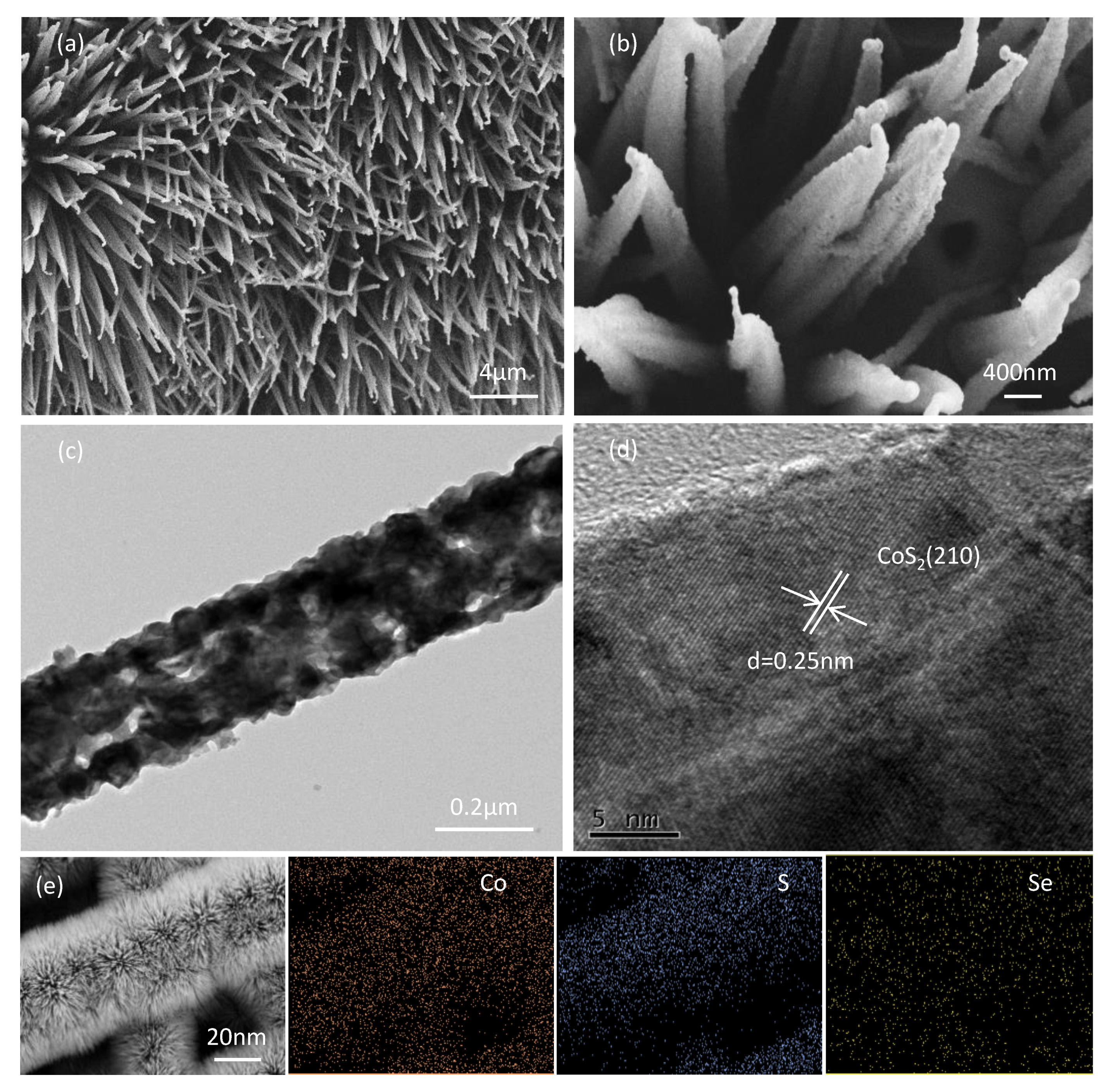
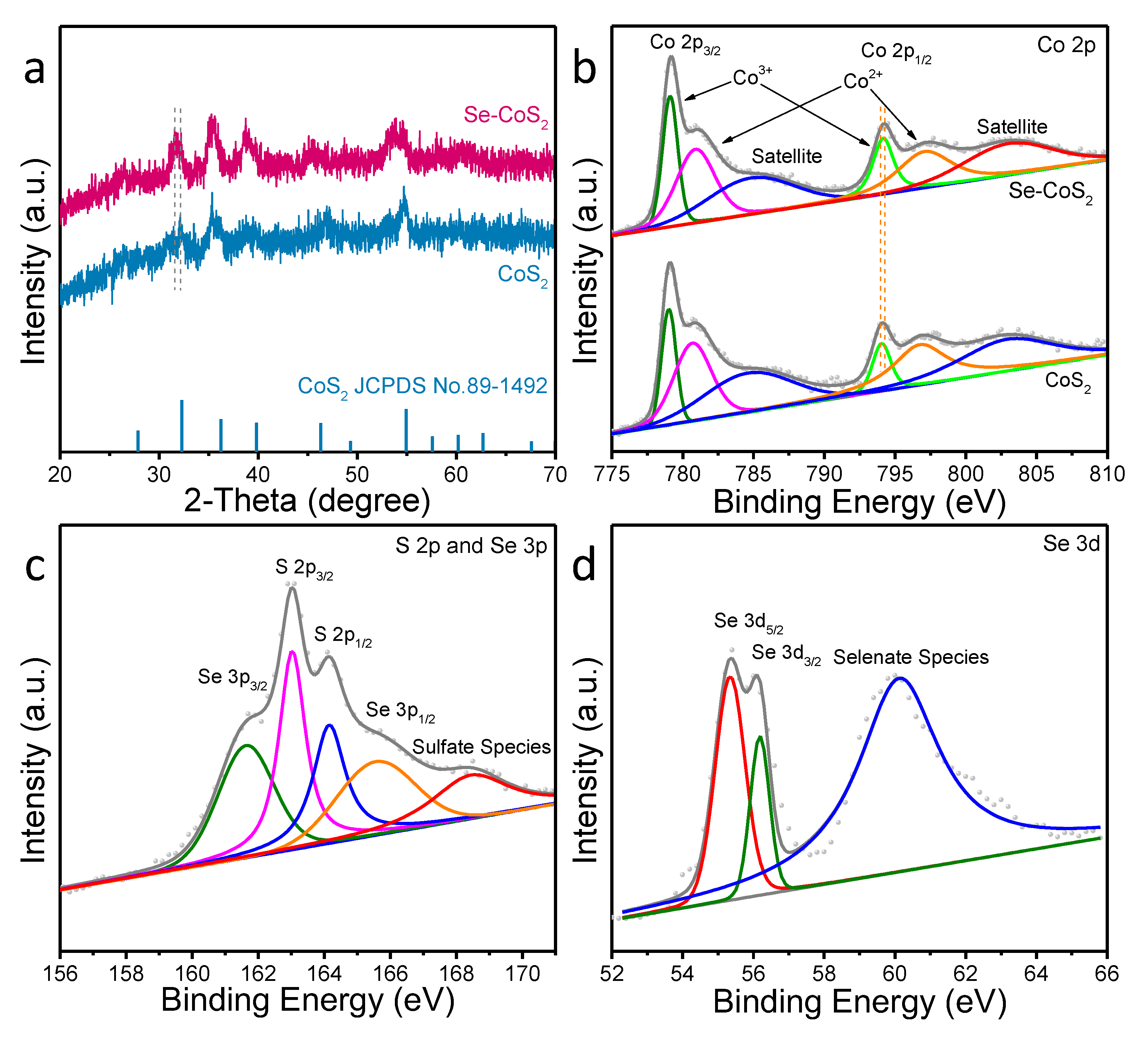
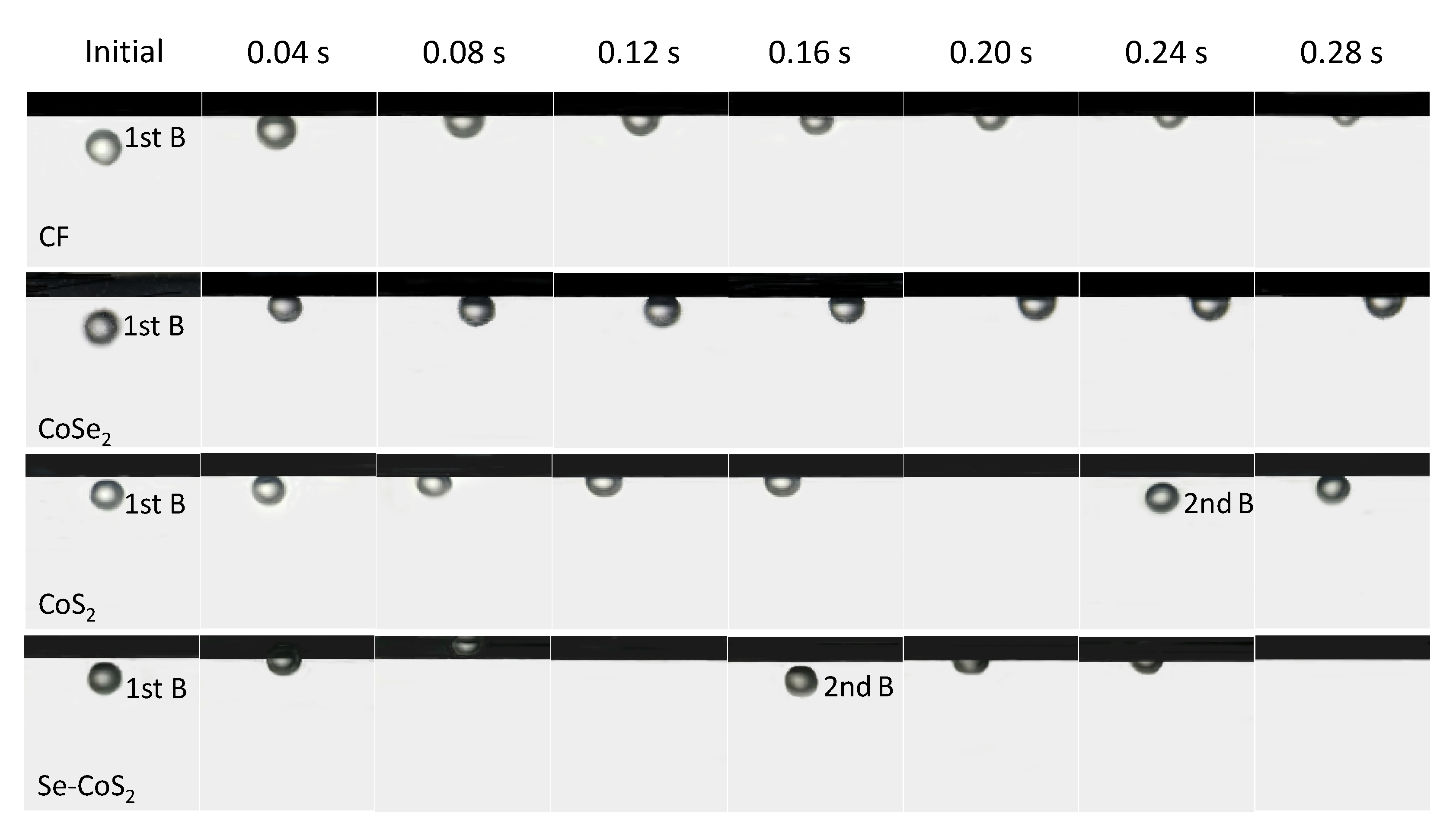
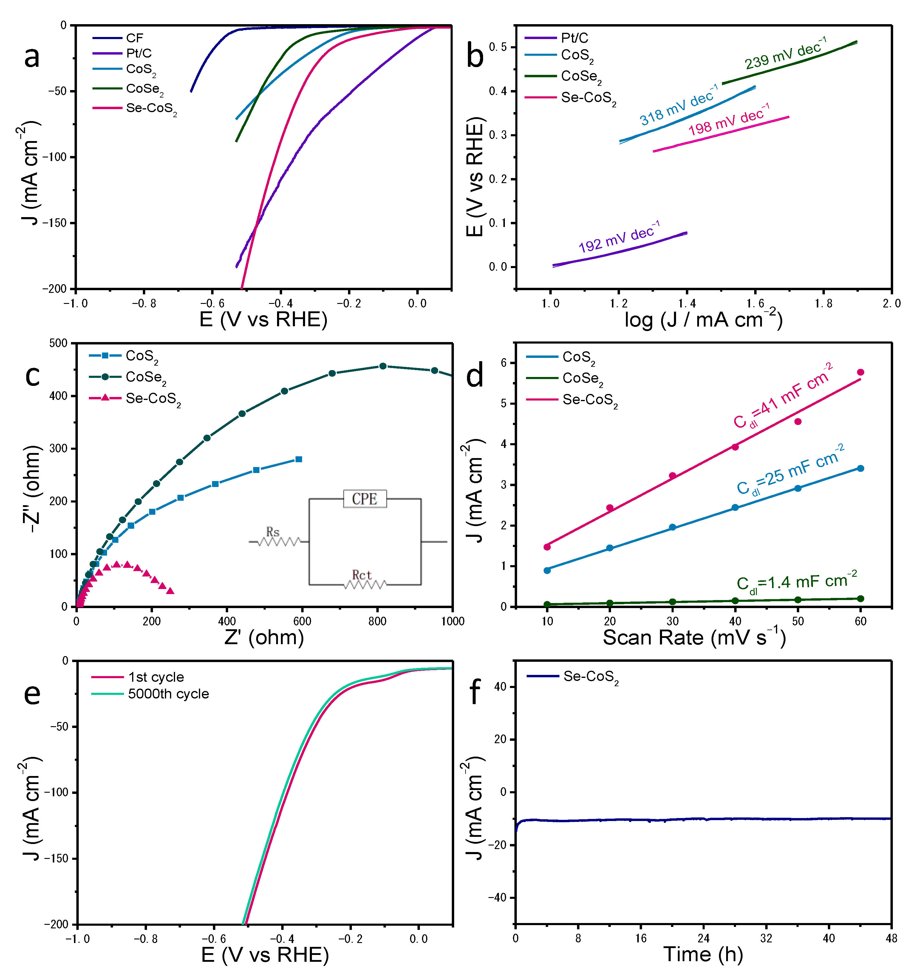
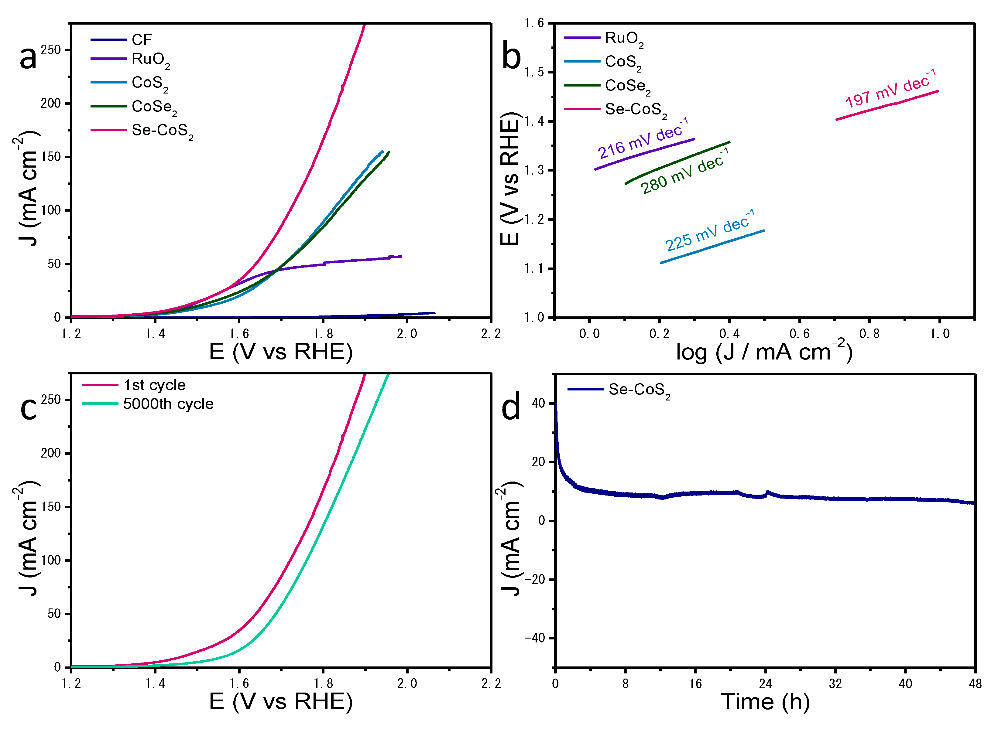
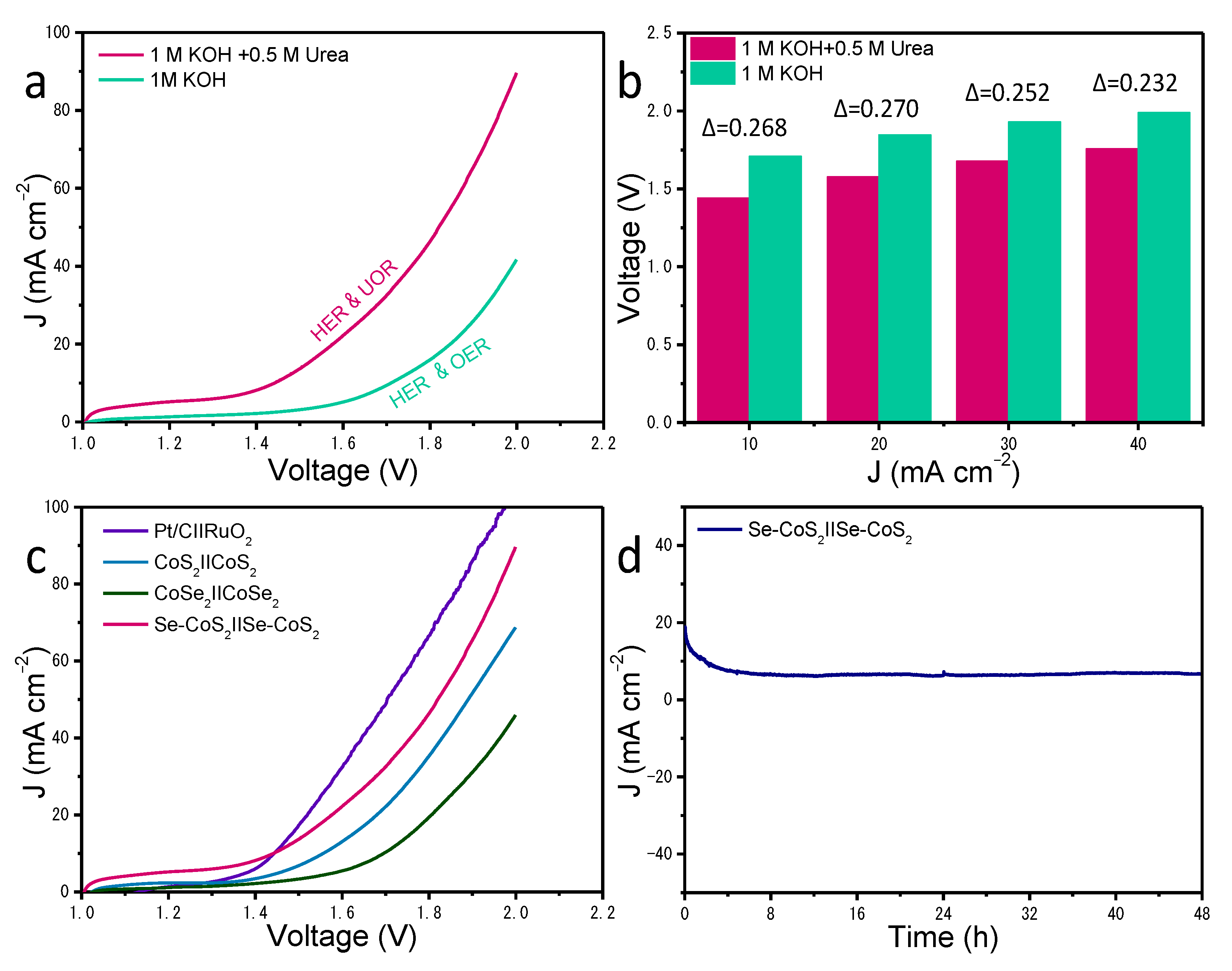
2. Results and Discussion

The Co(CO3)0.5(OH)·0.11 H2O was grown on carbon fiber by hydrothermal method (Supplementary Materials Figure S1). Then, the target sample was obtained by selenizing and sulfurizing Co(CO3)0.5(OH)·0.11H2O. The morphology and structure information of the obtained samples were characterized by using scanning electron microscopy (SEM) and transmission electron microscopy (TEM). Figure 1a shows a typical low-magnification SEM image of the obtained sample. It is clear that the sample has a nanowire-shape. And the nanowires are uniformly and neatly grown on the carbon fiber. The further observation of nanowires by SEM is shown in Figure 1b. It can be seen that the surface of nanowires is rough, and there are many small pores on the surface of nanowires. A typical TEM image in Figure 1c further shows the existence of small pores. These confirm the porous structure of nanowires. That may provide more active sites for an enhanced catalytic activity. The lattice spacing of the obtained sample was understood by high-resolution TEM (HRTEM). As shown in Figure 1d, it can be found that the lattice spacing of the sample is 0.25 nm, which can be assigned to the (210) plane of CoS2. Meanwhile, energy-dispersive spectroscopy (EDS) images in Figure 1e show the composition and distribution of Co, S, and Se elements. And it is obvious that they were evenly distributed in the whole nanowire. From the presence and uniform distribution of the Se element, it could deduce the incorporation of Se in CoS2.
X-ray powder diffraction (XRD) spectra of CoS2 NW/CF and Se-CoS2 NW/CF were performed to determine the composition of samples. It can be found in Figure 2a that the peaks position of the Se-CoS2 NW/CF are similar to that of CoS2 NW/CF. They match well with the pure CoS2 (JCPDS No. 89-1492). From the grey dotted line that is marked in Figure 2a, it is obvious that the peaks of Se-CoS2 NW/CF shift slightly to the low-angle region compared to the peaks of CoS2 NW/CF, which indicates the incorporation of Se does not damage the crystal structure of CoS2. But due to the larger radius of Se than that of S, the lattice expansion occurs after the incorporation of Se in CoS2 [31]. Furthermore, the surface-chemical property of Se-CoS2 NW/CF was studied by using X-ray photoelectron spectroscopy (XPS). Figure 2b prefers its Co 2p spectrum, it depicts that the two main peaks located at 779.1 and 794.2 eV are corresponding to the characteristic peaks of Co 2p3/2 and Co 2p1/2, respectively [32]. These two main peaks can be divided into four peaks located at 779.1, 780.9, 794.2, and 797.1 eV, separately. They can be ascribed to the coexistence of Co3+ (779.1 and 794.2 eV) and Co2+ (780.9 and 797.1 eV) [33]. Moreover, the peaks located at binding energy of 784.8 and 803.0 eV can be ascribed to satellite peaks of Co 2p3/2 and Co 2p1/2, respectively [34,35]. As the orange dotted line illustrated in Figure 2b, it is visible that the Co 2p1/2 peak of Se-CoS2 NW/CF shifts slightly to the higher binding energy region compared to that of CoS2 NW/CF. This phenomenon indicates the doping of Se can modulate the electronic structure of sample [36,37]. Which is expected to optimize the catalytic performance. The S 2p and Se 3p peaks of Se-CoS2 NW/CF is shown in Figure 2c. For S 2p and Se 3p, the peaks of S 2p3/2, S 2p1/2, Se 3p3/2 and Se 3p1/2 located at 163.0 eV, 164.1 eV, 161.6 eV and 165.6 eV, respectively [38]. And the peak located at 168.4 eV might be ascribed to S–O bonding [39]. In Figure 2d, the binding energy of the Se 3d region located at 55.3 eV and 56.2 eV, respectively. The first peak is Se 3d5/2 and the second peak is Se 3d3/2. And the peak at 60.1 eV suggests the presence of higher oxidation-state selenide species in the sample [40]. All the above data can indicate that the successful doping of Se into CoS2, thus the target Se-CoS2 NW/CF was successfully prepared. Furthermore, combined with the only one set of lattice fringe in HRTEM image, it could infer that the doping of Se is by replacing S in its crystal.
As verified by pioneer works, the contact area between catalysts and electrolyte has a great influence on their activity and stability [41,42]. With the catalyst working, a large amount of hydrogen bubbles will be generated. If the generated hydrogen bubbles accumulate on the catalyst surface, which would reduce the contact area and then slow down the electron and mass transfer, thus weaken its catalytic activity. Therefore, the rapid release of hydrogen bubbles on catalysts surface can promote their catalytic activity. Herein, we used air bubbles to simulate the release of hydrogen bubbles as the catalyst works, and the high-speed photographs of air bubbles escaping on electrodes are shown in Figure 3. As can be seen, the air bubbles fade away from the surface of CF, or escape from the surface of CoSe2 NW/CF, Se-CoS2 NW/CF, and CoS2 NW/CF by gradually moving from left to right-side of the sample. However, comparing with that on the surface of Se-CoS2 NW/CF, the air bubbles on CoS2 NW/CF will stay for a time. It is clearly shown in Figure 3, the air bubbles stayed on Se-CoS2 NW/CF for less than 0.12 s, and that stayed more than 0.16 s on CoS2 NW/CF, and more than 0.28 s on CF, and more than 0.28 s on CoSe2 NW/CF samples. It is obvious that the release of air bubbles on CF, CoS2 NW/CF, and CoSe2 NW/CF are much more difficult than that on Se-CoS2 NW/CF. It determines that Se-CoS2 NW/CF has a “superaerophobic” characteristic, which is conducive to the release of generated hydrogen on Se-CoS2 NW/CF during operation process to maintain its original active site. Meanwhile, the specific “superaerophobic” property ensures the in-time release of generated hydrogen bubbles, which make the catalyst to maintain its active area, resulting in a stable catalytic activity. Thus, the designed Se-CoS2 NW/CF may have excellent catalytic activity and long-term stability.
In order to study the effects of Se doping and unique surface on the HER performance of the catalyst, Se-CoS2 NW/CF as working electrode was electrochemically tested in 1 M KOH electrolyte which contained 0.5 M urea. For comparison, the electrochemical tests on bare CF, Pt/C, CoS2 NW/CF, and CoSe2 NW/CF were also performed. Figure 4a shows the linear sweep voltammetry (LSV) curves for all the above-mentioned samples. It is obvious that the Se-CoS2 NW/CF at 10 mA cm−2 has the lowest overpotential value of 188 mV; Being compared with that of CoS2 NW/CF (246 mV), CoSe2 NW/CF (335 mV) and bare CF 570 mV) at 10 mA cm−2, except Pt/C (4 mV). In addition, we also checked the HER performance of Se-CoS2 NW/CF in 1 M KOH electrolyte (Figure S2). The results showed that the addition of urea has an ignorable effect on the HER performance. Even compared with the reported works in literature, the as-prepared sample has a better HER performance in alkaline condition (Table S1). According to the aforementioned data, we may infer that the Se-CoS2 NW/CF has an excellent catalytic performance. That is to say, the doping of Se in CoS2 could lower the overpotential of HER, thus optimize the HER activity. Based on the LSV data in Figure 4a, a corresponding Tafel slope diagram was made to illustrate the reaction kinetics of samples. As presented in Figure 4b, the Tafel slopes of Pt/C, CoS2 NW/CF, CoSe2 NW/CF, and Se-CoS2 NW/CF are 192, 318, 239, and 198 mV dec−1, respectively. Although the Tafel slope of Se-CoS2 NW/CF is larger than that of Pt/C, it is much less than that of CoS2 NW/CF and CoSe2 NW/CF. It proves that the Se-CoS2 NW/CF has a better reaction kinetics than that of the CoS2 NW/CF and CoSe2 NW/CF [43]. That means the doping of Se optimized the reaction kinetics of CoS2.
In addition, we also measured the electrochemical impedance spectroscopy (EIS) of all samples. The Nyquist plot with an equivalent circuit in the inset of Figure 4c, the semicircle of Se-CoS2 NW/CF is much smaller than that of CoS2 NW/CF and CoSe2 NW/CF in the Nyquist plots. It indicates that the Se-CoS2 NW/CF has a smaller charge transfer resistance and a relative higher conductivity [44,45]. This may favor the charge transfer, thus improving the HER performance [46,47]. Meanwhile, the electrochemical double-layer capacitance (Cdl) was also measured at different scan rates from 10 mV s−1 to 60 mV s−1 (Figure S3a–c) to estimate electrochemically active surface area (ECSA) of samples. As presented in Figure 4d, the Cdl of Se-CoS2 NW/CF is calculated to 41 mF cm−2, which is greater than the Cdl of CoS2 NW/CF (25 mF cm−2) and CoSe2 NW/CF (1.4 mF cm−2). The larger ECSA of Se-CoS2 NW/CF could provide more active sites for electrocatalysis [48]. This result is in accordance with the description in SEM and TEM observation. Meanwhile, the stability of Se-CoS2 NW/CF electrode was evaluated through a long-term cyclic voltammogram (CV) cycling test and a chronopotentiometry curve. As depicted in Figure 4e, after 5000 cycles of continuous CV scans, the LSV curve of the Se-CoS2 NW/CF was substantially coincided with its first cycle. And after a continuous testing at 10 mA cm−2, the overpotential of Se-CoS2 NW/CF remained stable for a long period of 48 h, indicating the excellent stability of catalyst under urea containing alkaline electrolyte (Figure 4f). Moreover, in order to understand the morphology and composition information of the sample after HER test, SEM and XRD were performed after the long-term I-t test. As shown in Figure S4a,b, the morphology of the sample before and after I-t test changes very little, and the nanowires on the surface of the sample after I-t test have a slight aggregation, which is inevitable for long-term I-t test. And the XRD peaks position after the I-t test is also basically the same as its initial sample (Figure S5). Both of them further illustrate the good stability of Se-CoS2 NW/CF.
Furthermore, to investigate the feasibility of urea electrolysis, we checked out the UOR performance in 1 M KOH electrolyte which contained 0.5 M urea. Figure 5a depicts the LSV curves of RuO2, CoS2 NW/CF, CoSe2 NW/CF, and Se-CoS2 NW/CF. It is distinct that the Se-CoS2 NW/CF has a lower overpotential (1.46 V) compared to that of CoS2 NW/CF (1.52 V) and CoSe2 NW/CF (1.49 V) at 10 mA cm−2. Even better than that of RuO2 when the current density over 26 mA cm−2. This proves that Se-CoS2 NW/CF has the best UOR performance. In other words, the doping of Se can improve the UOR performance of CoS2. According to the comparison with the electrodes reported in recent years, the Se-CoS2 NW/CF has a best UOR performance (Table S2). Based on the data in Figure 5a, the Tafel slope graph of UOR was obtained. As shown in Figure 5b, the Tafel slopes of RuO2, CoS2 NW/CF, CoSe2 NW/CF, and Se-CoS2 NW/CF are 216, 225, 280, and 197 mV dec−1, respectively. It is clear that the Tafel slope of Se-CoS2 NW/CF is the smallest, which means that the Se-CoS2 NW/CF has the fastest UOR reaction kinetics. In addition, the effect of urea concentration on the UOR performance was also studied. It can be found in Figure S6a that when the concentration of urea is 0.5 M, the Se-CoS2 NW/CF has the best UOR performance. However, when the electrolyte is only 0.5 M urea without KOH, the current density is negligible (Figure S6b), which means that the UOR does not occur without KOH. Meanwhile, compared with pure KOH electrolyte without the addition of urea, Se-CoS2 NW/CF has significantly lowered the operated voltage in electrolyte with containing urea. It is in line with our expectation to replace the sluggish OER with UOR to improve the efficiency of hydrogen production. In order to better understand the UOR process, we conducted SEM, XRD and XPS characterization of electrode after UOR test. The SEM of electrode after the UOR test still maintains its nanowire structure, but the surface has changed, which is caused by the inevitable oxidation reaction during the UOR process (Figure S7a,b). As shown in Figure S8a, the XRD spectrum after the UOR test basically has no characteristic peaks, indicating that the surface of Se-CoS2 NW/CF may transform into an amorphous substance. Figure S8b–d show the comparison of XPS fine spectra of Se-CoS2 NW/CF after the UOR test. From the Co 2p spectrum could found that the Co–S/Se bonds basically disappeared and Co–O bonds strength increased [49]. And from the S 2p spectrum and the Se 3d spectrum, it is clear that the S–O bonds and the Se–O bonds are dominant, which may be caused by the surface oxidation during the UOR process [30]. Based on the XPS measurement and analysis, it may be speculated that the surface of Se-CoS2 NW/CF is oxidized to cobalt hydroxide/oxyhydroxide, and the oxidized cobalt hydroxide/oxyhydroxide may be the real active substance, while internal Se-CoS2 NW/CF plays an electron transfer role between the electrode and the active material, thereby improving the catalytic activity of UOR, which is consistent with the previous literature [50,51]. Meanwhile, we have also carried out the high-speed photographs of air bubbles escaping on Se-CoS2 NW/CF after UOR. As shown in Figure S9, the escape velocity of bubbles on Se-CoS2 NW/CF after UOR was slightly reduced, which was 0.04 s slower than before UOR. This is because the morphology of the catalyst surface had changed, but the overall effect is not significant. As the importance of stability for catalyst, the LSV curves of the Se-CoS2 NW/CF before and after 5000 cycles of continuous CV scans were determined. As depicted in Figure 5c, there has only 0.037 V of difference to the first cycle at the current density of 150 mA cm−2. When the overpotential of sample was set at 0.40 V, the current density still maintained after about 48 h of UOR operation (Figure 5d). In addition, we observed that the morphology of the samples after long-term I-t test was basically consistent with that after UOR test (Figure S10). All of them demonstrate that the UOR activity and stability could be well maintained. And all of them show that it is practicable to instead of the sluggish OER by the UOR using the as-prepared electrode.
In light of the good HER and UOR performance of the Se-CoS2 NW/CF, a two-electrode cell that use Se-CoS2 NW/CFs as both of anode and cathode electrodes was operated in urea containing alkaline electrolyte. For comparison, the same cell which was operated in alkaline electrolyte was also performed. As shown in Figure 6a, the voltage of overall urea electrolysis is significantly less than that of overall water electrolysis. When the current densities are 10, 20, 30 and 40 mA cm−2, the voltages difference are 0.268, 0.270, 0.252 and 0.232 V, respectively (Figure 6b). Which confirms that using UOR instead of OER can improve the efficiency of hydrogen production. Meanwhile, as presented in Figure 6c, when the current density is 10 mA cm−2, the cell voltages of CoS2 NW/CF || CoS2 NW/CF, CoSe2 NW/CF || CoSe2 NW/CF, and Se-CoS2 NW/CF || Se-CoS2 NW/CF are 1.55, 1.69, and 1.44 V, respectively. Furthermore, the cell voltage of Se-CoS2 NW/CF || Se-CoS2 NW/CF is less than most of reported ones (Table S3). The smallest cell voltage of Se-CoS2 NW/CF || Se-CoS2 NW/CF proves that the doping of Se improve the catalytic activity. Moreover, after continuous testing at a set cell voltage for 48 h, its current density still remained stable (Figure 6d). The afore-mentioned results indicate that the as-obtained Se-CoS2 NW/CF has the potential to be used as a low-cost and highly efficient hydrogen evolution electrode.
The stable and efficient of Se-CoS2 NW/CF for cost-saving hydrogen evolution main benefits from the following factors: (a) The Se-CoS2 NW/CF is directly grown on the conductive CF, which may enhance the conductivity thus improving the HER and UOR catalytic activity. (b) The Se doping reduces the charge transfer resistance thereby improving the HER and UOR catalytic activity. (c) The introduction of Se also changed the surface structure of CoS2, which accelerated the escape rate of gas bubbles on the surface of CoS2, thereby improving the HER activity and stability. (d) In addition, using UOR instead of OER lower the cell voltage, which fascinating the overall hydrogen production efficiency.

3. Materials and Methods

3.1. Materials

Cobalt nitrate hexahydrate, ammonium fluoride, urea, selenium and thiourea were purchased from Aladdin Chemistry Co., Ltd. (Shanghai, China). Ruthenium oxide and Platinum carbon catalyst (20 wt %) were purchased from Alfa Aesar Co., Ltd. (Tianjin, China). Nafion was purchased from Shanghai Hesen Electric Co., LTD (Shanghai, China). All the chemicals used in this work are of analytical grade without further treatment.

3.2. The Synthesis of Co(CO3)0.5(OH)·0.11H2O NW/CF

A common hydrothermal method was used to synthesize Co(CO3)0.5(OH)·0.11H2O on carbon fiber [41]. Carbon fibers (2.4 × 2 cm2) were sonicated in nitric acid, acetone, ethanol, and deionized water for 15 min, respectively. 4 mmol of Co(NO3)2·6H2O, 2 mmol of NH4F and 5 mmol of urea were dissolved in 20 mL of deionized water under stirring for 10 min. A piece of pretreated carbon fiber was put into the Teflon-lined stainless-steel autoclave, and the prepared solution was transferred in. Then the autoclave was sealed and held at 120 °C for 12 h. After that it was cooled down to room temperature naturally. The obtained carbon fiber was rinsed with distilled water and alcohol for several times, and finally was dried in an oven at 60 °C.

3.3. The Synthesis of Se-CoS2 NW/CF, CoS2 NW/CF, and CoSe2 NW/CF

A piece of obtained carbon fiber and 0.2 g of selenium powder were separately placed in two porcelain vessels. The boat with selenium powder was seated at upstream in the tubular furnace, and the boat with carbon fiber was seated at downstream part. With a heating rate of 2 °C min−1 and Ar as a protective gas, the tubular furnace was held at 350 °C for 2 h. After that the tubular furnace was cooled to room temperature for the next step. Following, the selenium was replaced by 0.6 g of thiourea, and the temperature was raised to 500 °C, the same pyrolysis procedure as mentioned above was carried out again. After cooled to room temperature, Se-CoS2 NW/CF was obtained. The synthesis step of CoSe2 NW/CF was similar to the first step of Se-CoS2 NW/CF, and 0.2 g of selenium was changed to 0.8 g; The synthesis step of CoS2 NW/CF was similar to the second step of Se-CoS2 NW/CF, and 0.6 g of thiourea was changed to 0.8 g.

3.4. Materials Characterization

Field-emission SEM (ZEISS-SUPRA 55 Sapphire, Jena, Germany) and TEM (JEOL JEM-2100, Tokyo, Japan) were used to characterize the morphology information of the prepared samples. EDS (Oxford X-act, Oxford, UK) was selected to characterize the composition of samples. XRD (Philips X’pert PRO, Almelo, the Netherlands; Cu Kα, λ = 0.1524 nm) and HRTEM that works at an acceleration voltage of 200 kV (JEOL JEM-2100) were performed to characterize the crystal information of samples. And XPS (ESCALab 250, Waltham, MA, USA) was used to further analyze the chemical composition of samples.

3.5. Electrochemical Measurements

Electrochemical performance tests were performed on a workstation (CHI660E, Shanghai, China) using a three-electrode system. A saturated calomel electrode was used as the reference electrode, a graphite rod electrode was used as the counter electrode, and the prepared sample was used as the working electrode. Before the LSV tests, the CV scan was firstly operated at a scan rate of 100 mV s−1 for several times. Then the scan rate for LSV test was settled at 2 mV s−1. EIS was measured at overpotential of −220 mV vs. RHE with a frequency range of 100 kHz to 10 mHz. ECSA was tested with a voltage from 0.788 to 0.888 V vs. RHE in the scan range of 10 to 60 mV s−1. The iR correction was performed on all of the obtained data.

4. Conclusions

In summary, we synthesized the Se doped CoS2 porous nanowires array on carbon fiber by a simple hydrothermal method combined with pyrolysis process. Benefiting from the unique porous structure and superaerophobic surface of Se-CoS2 NW/CF, the obtained Se-CoS2 NW/CF with a more exposure of active sites and a promotion release of generated gas bubbles, lead to an excellent low-cost hydrogen evolution and a long-term stability of electrode in the urea-containing electrolyte. At a current density of 10 mA cm−2, the overpotentials of HER and UOR are 188 mV and 1.46 V, respectively. And the cell voltage of the Se-CoS2 NW/CF || Se-CoS2 NW/CF is low as 1.44 V. In addition, under the set overpotentials, the current densities of HER and UOR, as well as cell remained basically unchanged after a continuous operation for 48 h. This work provides a new applicable way to improve the activity and stability of TMDs, and as well as open minds for design of energy saving electrocatalysis.

Supplementary Materials

The following are available online at https://0-www-mdpi-com.brum.beds.ac.uk/2073-4344/11/2/169/s1, Figure S1: XRD spectrum of Co(CO3)0.5OH·0.11H2O NW/CF, Figure S2: HER polarization curves of Se-CoS2 NW/CF in 1.0 M KOH with and without 0.5 M urea, Figure S3: (a–c) CV curves of CoS2 NW/CF, CoSe2 NW/CF, and Se-CoS2 NW/CF in 1.0 M KOH with 0.5 M urea, Figure S4: (a) Low- and (b) high-magnification SEM images of Se-CoS2 NW/CF after I-t test, Figure S5: XRD spectrum of Se-CoS2 NW/CF after I-t test, Figure S6: (a) UOR polarization curves of Se-CoS2 NW/CF catalyst in 1 M KOH with various urea concentrations. (b) UOR polarization curves of Se-CoS2 NW/CF in 1.0 M KOH with 0.5 M urea, 1.0 M KOH, and 0.5 M urea, Figure S7: (a) Low- and (b) high-magnification SEM images of Se-CoS2 NW/CF after UOR test, Figure S8: (a) XRD spectrum of Se-CoS2 NW/CF after UOR test. XPS spectra of (b) Co 2p, (c) S 2p and Se 3p, and (d) Se 3d of Se-CoS2 NW/CF after UOR test, Figure S9: High-speed photographs of air bubbles escaping on the surface of Se-CoS2 NW/FC after UOR test, Figure S10. SEM image of Se-CoS2 NW/CF after I-t test, Table S1: Comparison of the HER performance of Se-CoS2 NW/CF with other reported catalysts, Table S2: Comparison of the UOR performance of Se-CoS2 NW/CF catalyst with other reported UOR catalysts, Table S3: Comparison of the activity of urea electrocatalysis with other reported ones.

Author Contributions

Conceptualization, methodology, software, validation, formal analysis, investigation, data curation and writing—original draft preparation, Y.T., Y.Y., C.L. and Y.W.; resources, writing—review and editing, visualization, Y.M.; supervision, X.Y. and F.H.; project administration, funding acquisition, Q.H. All authors have read and agreed to the published version of the manuscript.

Funding

This research was funded by the National Natural Science Foundation of China, (Grant Nos. 31860192, 21761004, 21701035), the Natural Science Foundation of Guangxi (Grant Nos. 2018GXNSFBA281085, 2018GXNSFAA138126), the Specific research project of Guangxi for research bases and talents (Grant Nos. AD18126002, AD18126005), the foundation ability enhancement project of young teachers in Guangxi universities (Grant Nos. 2018KY0163), the Guangxi University for Nationalities Graduate Education Innovation Project (Grant Nos. gxun-chxzs2019015), the 100 Talents Program for Introducing Overseas High-level Talents into Universities of Guangxi and the training program for thousands of backbone young teachers in Guangxi universities.

Conflicts of Interest

The authors declare no conflict of interest.

References

  1. Yan, J.W.; Wei, Z.D.; Xu, M.Q.; Jiang, Z.; Shang-Guan, W.F. Polyoxometalate template-based synthetic strategy to prepare Ni, Mo Co-doped CdS for efficient photocatalytic hydrogen evolution from water splitting. Catalysts 2020, 10, 1478. [Google Scholar] [CrossRef]
  2. Adesuji, E.T.; Guardado-Villegas, E.; Fuentes, K.M.; Sánchez-Domínguez, M.; Videa, M. Pt-Co3O4 Superstructures by one-pot reduction/precipitation in bicontinuous microemulsion for electrocatalytic oxygen evolution reaction. Catalysts 2020, 10, 1311. [Google Scholar] [CrossRef]
  3. Li, Q.; Liu, W.L.; Xie, X.J.; Yang, X.L.; Chen, X.F.; Xu, X.G. synthesis and characterization of amorphous molybdenum sulfide (MoSx)/CdIn2S4 composite photocatalyst: Co-catalyst using in the hydrogen evolution reaction. Catalysts 2020, 10, 1455. [Google Scholar] [CrossRef]
  4. Yang, H.; He, Q.Y.; Liu, Y.W.; Li, H.Q.; Zhang, H.; Zha, T.Y. On-chip electrocatalytic microdevice: An emerging platform for expanding the insight into electrochemical processes. Chem. Soc. Rev. 2020, 49, 2916–2936. [Google Scholar] [CrossRef]
  5. Liu, Y.W.; Xiao, C.; Huang, P.C.; Cheng, M.; Xie, Y. Regulating the charge and spin ordering of two-dimensional ultrathin solids for electrocatalytic water splitting. Chem 2018, 4, 1263–1283. [Google Scholar] [CrossRef] [Green Version]
  6. Kong, N.; Han, B.; Li, Z.; Fang, Y.S.; Feng, K.; Wu, Z.Y.; Wang, S.H.; Xu, A.B.; Yu, Y.Y.; Li, C.R.; et al. Ruthenium nanoparticles supported on Mg(OH)2 microflowers as catalysts for photothermal carbon dioxide hydrogenation. ACS Appl. Nano Mater. 2020, 3, 3028–3033. [Google Scholar] [CrossRef]
  7. Zhuang, Z.C.; Li, Y.; Huang, J.Z.; Li, Z.; Zhao, K.N.; Zhao, Y.L.; Xu, L.; Zhou, L.; Moskaleva, L.V.; Mai, L.Q. Sisyphus effects in hydrogen electrochemistry on metal silicides enabled by silicene subunit edge. Sci. Bull. 2019, 64, 617–624. [Google Scholar] [CrossRef] [Green Version]
  8. Guo, B.; Li, H.Y.; Chen, J.Y.; Young, D.J.; Lang, J.P.; Li, H.X. Conjugated nanoporous polycarbazole bearing a cobalt complex for efficient visible-light driven hydrogen evolution. New J. Chem. 2020, 44, 8736–8742. [Google Scholar] [CrossRef]
  9. Chen, P.Z.; Zhou, T.P.; Chen, M.L.; Tong, Y.; Zhang, N.; Peng, X.; Chu, W.S.; Wu, X.J.; Wu, C.Z.; Xie, Y. Enhanced catalytic activity in nitrogen-anion modified metallic cobalt disulfide porous nanowire arrays for hydrogen evolution. ACS Catal. 2017, 7, 7405–7411. [Google Scholar] [CrossRef]
  10. Li, C.C.; Hou, J.X.; Wu, Z.X.; Guo, K.; Wang, D.L.; Zhai, T.Y.; Li, H.Q. Acid promoted Ni/NiO monolithic electrode for overall water splitting in alkaline medium. Sci. China Mater. 2017, 60, 918–928. [Google Scholar] [CrossRef] [Green Version]
  11. Zhu, H.; Gao, G.H.; Du, M.L.; Zhou, J.H.; Wang, K.; Wu, W.B.; Chen, X.; Li, Y.; Ma, P.M.; Dong, W.F.; et al. Atomic-scale core/shell structure engineering induces precise tensile strain to boost hydrogen evolution catalysis. Adv. Mater. 2018, 30, 1707301. [Google Scholar] [CrossRef] [PubMed]
  12. Zhu, H.; Gu, L.; Yu, D.N.; Sun, Y.J.; Wan, M.; Zhang, M.; Wang, L.; Wang, L.N.; Wu, W.W.; Yao, J.M.; et al. The marriage and integration of nanostructures with different dimensions for synergistic electrocatalysis. Energy Environ. Sci. 2017, 10, 321–330. [Google Scholar] [CrossRef]
  13. Li, Y.; Li, F.; Zhao, Y.; Li, S.N.; Zeng, J.H.; Yao, H.C.; Chen, Y. Iron doped cobalt phosphide ultrathin nanosheets on nickel foam for overall water splitting. J. Mater. Chem. A 2019, 7, 20658–20666. [Google Scholar] [CrossRef]
  14. Dou, S.; Dong, C.L.; Hu, Z.; Huang, Y.C.; Chen, J.L.; Tao, L.; Yan, D.; Chen, D.; Shen, S.; Chou, S.; et al. Atomic-scale CoOx species in metal-organic frameworks for oxygen evolution reaction. Adv. Funct. Mater. 2017, 27, 1702546. [Google Scholar] [CrossRef] [Green Version]
  15. Chen, P.Z.; Xu, K.; Zhou, T.P.; Tong, Y.; Wu, J.C.; Cheng, H.; Lu, X.L.; Ding, H.; Wu, C.Z.; Xie, Y. Strong-coupled cobalt borate nanosheets/graphene hybrid as electrocatalyst for water oxidation under both alkaline and neutral conditions. Angew. Chem. Int. Ed. Engl. 2016, 55, 2488–2492. [Google Scholar] [CrossRef]
  16. Xiong, T.; Tan, Z.Y.; Mi, Y.; Huang, Q.; Tan, Y.; Yin, X.H.; Hu, F.L. On-site generated metal organic framework-deriving core/shell ZnCo2O4/ZnO nanoarray for better water oxidation. Nanotechnology 2019, 30, 495405. [Google Scholar] [CrossRef]
  17. Li, C.C.; Liu, Y.W.; Zhuo, Z.W.; Ju, H.X.; Li, D.; Guo, Y.P.; Wu, X.J.; Li, H.Q.; Zhai, T.Y. Local charge distribution engineered by schottky heterojunctions toward urea electrolysis. Adv. Energy Mater. 2018, 8, 1801775. [Google Scholar] [CrossRef]
  18. Yu, Z.Y.; Lang, C.C.; Gao, M.R.; Chen, Y.; Fu, Q.Q.; Duan, Y.; Yu, S.H. Ni–Mo–O nanorod-derived composite catalysts for efficient alkaline water-to-hydrogen conversion via urea electrolysis. Energy Environ. Sci. 2018, 11, 1890–1897. [Google Scholar] [CrossRef]
  19. Sheng, C.; Jing, D.J.; Anthony, V.; Zhang, Q.S. Size fractionation of two-dimensional sub-nanometer thin manganese dioxide crystals towards superior urea electrocatalytic conversion. Angew. Chem. Int. Ed. 2016, 55, 3804–3808. [Google Scholar]
  20. Guo, F.; Ye, K.; Cheng, K.; Wang, G.L.; Cao, D.X. Preparation of nickel nanowire arrays electrode for urea electro-oxidation in alkaline medium. J. Power Sources 2015, 278, 562–568. [Google Scholar] [CrossRef]
  21. Zhang, S.C.; Xiong, T.; Tang, X.F.; Ma, Q.Y.; Hu, F.L.; Mi, Y. Engineering inner-porous cobalt phosphide nanowire based on controllable phosphating for efficient hydrogen evolution in both acidic and alkaline conditions. Appl. Surf. Sci. 2019, 481, 1524–1531. [Google Scholar] [CrossRef]
  22. Gong, Y.Z.; Lv, F.; Lu, Y.D.; Yu, Y.L.; Niu, J.L.; Lang, J.P.; Deng, Y.Y.; Cao, X.Q.; Gu, H.W. In situ surface-derivation of AgPdMo/MoS2 nanowires for synergistic hydrogen evolution catalysis in alkaline solution. Nanoscale 2020, 12, 6472–6497. [Google Scholar] [CrossRef] [PubMed]
  23. Xiong, T.; Li, G.F.; Young, D.J.; Tan, Z.Y.; Yin, X.H.; Mi, Y.; Hu, F.L. In-situ surface-derivation of Ni-Mo bimetal sulfides nanosheets on Co3O4 nanoarrays as an advanced overall water splitting electrocatalyst in alkaline solution. J. Alloys Compd. 2019, 791, 328–335. [Google Scholar] [CrossRef]
  24. Zhang, Y.P.; Zhang, M.; Chen, X.R.; Lu, C.R.; Young, D.J.; Ren, Z.G.; Lang, J.P. Cobalt(II) and Nickel(II) complexes of a PNN type ligand as photoenhanced electrocatalysts for the hydrogen evolution reaction. Inorg. Chem. 2020, 59, 1038–1045. [Google Scholar] [CrossRef]
  25. Luo, Z.M.; Wang, J.W.; Tan, J.B.; Zhang, Z.M.; Lu, T.B. Self-template synthesis of Co-Se-S-O hierarchical nanotubes as efficient electrocatalysts for oxygen evolution under alkaline and neutral conditions. ACS Appl. Mater. Interfaces 2018, 10, 8231–8237. [Google Scholar] [CrossRef]
  26. Zhang, J.Y.; Liu, Y.C.; Sun, C.Q.; Xi, P.X.; Peng, S.L.; Gao, D.Q.; Xue, D.S. Accelerated hydrogen evolution reaction in CoS2 by transition-metal doping. ACS Energy Lett. 2018, 3, 779–786. [Google Scholar] [CrossRef]
  27. Li, J.Y.; Xia, Z.M.; Zhang, M.K.; Zhang, S.; Li, J.; Ma, Y.Y.; Qu, Y.Q. Ce-doped CoS2 pyrite with weakened O2 adsorption suppresses catalyst leaching and stabilizes electrocatalytic H2 evolution. J. Mater. Chem. A 2019, 7, 17775–17781. [Google Scholar] [CrossRef]
  28. Lin, J.H.; Zhong, Z.X.; Wang, H.H.; Zheng, X.H.; Wang, Y.H.; Qi, J.L.; Cao, J.; Fei, W.D.; Huang, Y.D.; Feng, J.C. Rational constructing free-standing Se doped nickel-cobalt sulfides nanotubes as battery-type electrode for high-performance supercapattery. J. Power Sources 2018, 407, 6–13. [Google Scholar] [CrossRef]
  29. Wang, Y.Q.; Jian, C.Y.; Hong, W.T.; Cai, Q.; Liu, W. Tuning the electron status of urchin-like CoS2 nanowires by selenium doping toward highly efficient hydrogen evolution reaction. Mater. Lett. 2019, 257, 126673. [Google Scholar] [CrossRef]
  30. Zhang, Y.Y.; Qiu, Y.F.; Ji, X.Y.; Ma, T.G.; Ma, Z.; Hu, P.A. Direct growth of CNTs@CoSx Se2(1−x) on carbon cloth for overall water splitting. ChemSusChem 2019, 12, 3792–3800. [Google Scholar] [CrossRef]
  31. Zhou, G.Y.; Li, M.; Li, Y.L.; Dong, H.; Sun, D.M.; Liu, X.; Xu, L.; Tian, Z.Q.; Tang, Y.W. Regulating the electronic structure of CoP nanosheets by O incorporation for high-efficiency electrochemical overall water splitting. Adv. Funct. Mater. 2019, 30, 1905252. [Google Scholar] [CrossRef]
  32. He, W.D.; Liang, Z.F.; Ji, K.Y.; Sun, Q.F.; Zhai, T.Y.; Xu, X.J. Hierarchical Ni-Co-S@Ni-W-O core–shell nanosheet arrays on nickel foam for high-performance asymmetric supercapacitors. Nano Res. 2018, 11, 1415–1425. [Google Scholar] [CrossRef]
  33. Hui, H.J.; Shu, Y.W.; Zhen, P.; Chi, Z.; Peng, H.Z.; Dong, S.W. A nitrogen doping method for CoS2 electrocatalysts with enhanced water oxidation performance. ACS Catal. 2017, 7, 4214–4220. [Google Scholar]
  34. Cui, X.D.; Xie, Z.Q.; Wang, Y. Novel CoS2 embedded carbon nanocages by direct sulfurizing metal-organic frameworks for dye-sensitized solar cells. Nanoscale 2016, 8, 11984–11992. [Google Scholar] [CrossRef] [PubMed]
  35. Qiu, L.J.; Jiang, L.J.; Ye, Z.F.; Liu, Y.Y.; Cen, T.L.; Peng, X.M.; Yuan, D.S. Phosphorus-doped Co3Mo3C/Co/CNFs hybrid: A remarkable electrocatalyst for hydrogen evolution reaction. Electrochim. Acta 2019, 325, 134962. [Google Scholar] [CrossRef]
  36. Liu, T.; Li, P.; Yao, N.; Cheng, G.Z.; Chen, S.L.; Luo, W.; Yin, Y.D. Phosphorus-doped Co3Mo3C/Co/CNFs hybrid: A remarkable electrocatalyst for hydrogen evolution reaction. Angew. Chem. Int. Ed. Engl. 2019, 58, 4679–4684. [Google Scholar] [CrossRef]
  37. Men, Y.N.; Li, P.; Yang, F.L.; Cheng, G.Z.; Chen, S.L.; Luo, W. Nitrogen-doped CoP as robust electrocatalyst for high-efficiency pH-universal hydrogen evolution reaction. Appl. Catal. B 2019, 253, 21–27. [Google Scholar] [CrossRef]
  38. Liu, K.L.; Wang, F.M.; Xu, K.; Shifa, T.A.; Cheng, Z.Z.; Zhan, X.Y.; He, J. CoS2xSe2(1−x) nanowire array: An efficient ternary electrocatalyst for the hydrogen evolution reaction. Nanoscale 2016, 8, 4699–4704. [Google Scholar] [CrossRef]
  39. Fang, L.; Zhang, Y.; Guan, Y.X.; Zhang, H.J.; Wang, S.L.; Wang, Y. Specific synthesis of CoS2 nanoparticles embedded in porous Al2O3 nanosheets for efficient hydrogen evolution and enhanced lithium storage. J. Mater. Chem. A 2017, 5, 2861–2869. [Google Scholar] [CrossRef]
  40. He, Q.; Li, S.L.; Huang, S.W.; Xiao, L.Q.; Hou, L.X. Construction of uniform Co-Sn-X (X = S, Se, Te) nanocages with enhanced photovoltaic and oxygen evolution properties via anion exchange reaction. Nanoscale 2018, 10, 22012–22024. [Google Scholar] [CrossRef]
  41. Zhang, S.C.; Wang, W.B.; Hu, F.L.; Mi, Y.; Wang, S.Z.; Liu, Y.W.; Ai, X.M.; Fang, J.K.; Li, H.Q.; Zhai, T.Y. 2D CoOOH sheet-encapsulated Ni2P into tubular arrays realizing 1000 mA cm−2-level-current-density hydrogen evolution over 100 h in neutral water. Nanomicro Lett. 2020, 12, 140. [Google Scholar] [CrossRef]
  42. Yu, X.X.; Yu, Z.Y.; Zhang, X.L.; Zheng, Y.R.; Duan, Y.; Gao, Q.; Wu, R.; Sun, B.; Gao, M.R.; Wang, G.X.; et al. “Superaerophobic” nickel phosphide nanoarray catalyst for efficient hydrogen evolution at ultrahigh current densities. J. Am. Chem. Soc. 2019, 141, 7537–7543. [Google Scholar] [CrossRef] [PubMed]
  43. Zhang, R.; Ren, X.; Hao, S.; Ge, R.X.; Liu, Z.; Asiri, A.M.; Chen, L.; Zhang, Q.J.; Sun, X.P. Selective phosphidation: An effective strategy toward CoP/CeO2 interface engineering for superior alkaline hydrogen evolution electrocatalysis. J. Mater. Chem. A 2018, 6, 1985–1990. [Google Scholar] [CrossRef]
  44. Xiong, J.; Li, X.B.; Huang, J.T.; Gao, X.M.; Chen, Z.; Liu, J.Y.; Li, H.; Kang, B.B.; Yao, W.Q.; Zhu, Y.F. CN/rGO@BPQDs high-low junctions with stretching spatial charge separation ability for photocatalytic degradation and H2O2 production. Appl. Catal. B 2020, 266, 118602. [Google Scholar] [CrossRef]
  45. Li, X.B.; Xiong, J.; Xu, Y.; Feng, Z.J.; Huang, J.T. Defect-assisted surface modification enhances the visible light photocatalytic performance of g-C3N4@C-TiO2 direct Z-scheme heterojunctions. Chin. J. Catal. 2019, 40, 424–433. [Google Scholar] [CrossRef]
  46. Dai, S.M.; Yuan, Y.; Yu, J.S.; Tang, J.; Zhou, J.; Tang, W.H. Metal-organic framework-templated synthesis of sulfur-doped core-sheath nanoarrays and nanoporous carbon for flexible all-solid-state asymmetric supercapacitors. Nanoscale 2018, 10, 15454–15461. [Google Scholar] [CrossRef]
  47. Cao, L.M.; Hu, Y.W.; Tang, S.F.; Iljin, A.; Wang, J.W.; Zhang, Z.M.; Lu, T.B. Fe-CoP electrocatalyst derived from a bimetallic prussian blue analogue for large-current-density oxygen evolution and overall water splitting. Adv. Sci. 2018, 5, 1800949. [Google Scholar] [CrossRef]
  48. Yu, H.J.; Li, J.Y.; Zhang, Y.H.; Yang, S.Q.; Han, K.L.; Dong, F.; Ma, T.Y.; Huang, H.W. Three-in-one oxygen vacancies: Whole visible-spectrum absorption, efficient charge separation, and surface site activation for robust CO2 photoreduction. Angew. Chem. Int. Ed. Engl. 2019, 58, 3880–3884. [Google Scholar] [CrossRef]
  49. Lu, J.Y.; Cai, L.J.; Zhang, N.; Qiu, B.C.; Chai, Y. Robust photoelectrochemical oxygen evolution with N, Fe-CoS2 nanorod arrays. ACS Appl. Mater. Interfaces 2019, 11, 44214–44222. [Google Scholar] [CrossRef]
  50. Ji, L.L.; Wang, J.Y.; Teng, X.; Meyer, T.J.; Chen, Z.F. CoP nanoframes as bifunctional electrocatalysts for efficient overall water splitting. ACS Catal. 2019, 10, 412–419. [Google Scholar] [CrossRef] [Green Version]
  51. Hu, E.L.; Ning, J.Q.; Zhao, D.; Xu, C.Y.; Lin, Y.Y.; Zhong, Y.J.; Zhang, Z.Y.; Wang, Y.J.; Hu, Y. A room-temperature postsynthetic ligand exchange strategy to construct mesoporous Fe-doped CoP hollow triangle plate arrays for efficient electrocatalytic water splitting. Small 2018, 14, 1704233. [Google Scholar] [CrossRef] [PubMed]
Figure 1. (a) Low- and (b) high-magnification scanning electron microscopy (SEM) images of Se-CoS2 NW/CF. (c) transmission electron microscopy (TEM) and (d) high-resolution TEM (HRTEM) images of Se-CoS2 NW/CF. (e) The SEM image and corresponding elemental mapping images for Se-CoS2 NW/CF.
Catalysts 11 00169 g001
Figure 2. (a) X-ray powder diffraction (XRD) spectra of CoS2 NW/CF and Se-CoS2 NW/CF. (b) X-ray photoelectron spectroscopy (XPS) spectra of Co 2p for Se-CoS2 NW/CF and CoS2 NW/CF. (c) XPS spectrum of S 2p and Se 3p for Se-CoS2 NW/CF. (d) XPS spectrum of Se 3d for Se-CoS2 NW/CF.
Catalysts 11 00169 g002
Figure 3. High-speed photographs of air bubbles escaping on bare CF, CoSe2 NW/CF, CoS2 NW/CF, and Se-CoS2 NW/FC surfaces.
Catalysts 11 00169 g003
Figure 4. (a) HER polarization curves of bare CF, Pt/C, CoS2 NW/CF, CoSe2 NW/CF, and Se-CoS2 NW/CF in 1.0 M KOH with 0.5 M urea. (b) Tafel plots of Pt/C, CoS2 NW/CF, CoSe2 NW/CF, and Se-CoS2 NW/CF. (c) Nyquist plots of CoS2 NW/CF, CoSe2 NW/CF, and Se-CoS2 NW/CF in 1.0 M KOH with 0.5 M urea. (d) The Cdl linear fitting and calculation of CoS2 NW/CF, CoS2 NW/CF, and Se-CoS2 NW/CF in 1.0 M KOH with 0.5 M urea. (e) HER polarization curves of Se-CoS2 NW/CF before and after 5000 cycles in 1.0 M KOH with 0.5 M urea. (f) Long-term stability test for Se-CoS2 NW/CF at a current density of 10 mA cm−2 in 1.0 M KOH with 0.5 M urea.
Catalysts 11 00169 g004
Figure 5. (a) UOR polarization curves of bare CF, RuO2, CoS2 NW/CF, CoSe2 NW/CF, and Se-CoS2 NW/CF in 1.0 M KOH with 0.5 M urea. (b) Tafel plots of RuO2, CoS2 NW/CF, CoSe2 NW/CF, and Se-CoS2 NW/CF. (c) UOR polarization curves of Se-CoS2 NW/CF before and after 5000 cycles in 1.0 M KOH with 0.5 M urea. (d) Long-term stability test for Se-CoS2 NW/CF at a current density of 10 mA cm−2 in 1.0 M KOH with 0.5 M urea.
Catalysts 11 00169 g005
Figure 6. (a) Polarization curves for the Se-CoS2 NW/CF || Se-CoS2 NW/CF in 1.0 M KOH with and without 0.5 M urea. (b) The corresponding voltages of Se-CoS2 NW/CF || Se-CoS2 NW/CF at 10, 20, 30 and 40 mA cm−2, respectively. (c) Polarization curves of Pt/C || RuO2, CoS2 NW/CF || CoS2 NW/CF, CoSe2 NW/CF || CoSe2 NW/CF, and Se-CoS2 NW/CF || Se-CoS2 NW/CF in 1.0 M KOH with 0.5 M urea. (d) Long-term stability test of Se-CoS2 NW/CF for the urea electrolysis.
Catalysts 11 00169 g006
Publisher’s Note: MDPI stays neutral with regard to jurisdictional claims in published maps and institutional affiliations.

