
High Oxygen Reduction Activity of Pt-Ni Alloy Catalyst for Proton Exchange Membrane Fuel Cells

1
School of Physics, Nanjing University, Nanjing 210093, China
2
Nanjing Doinpower Technology Co., Ltd., Nanjing 211100, China
3
Beijing Institute of Space Launch Technology, Beijing 100076, China
4
National Laboratory of Solid State Microstructures, Nanjing 210093, China
*
Author to whom correspondence should be addressed.
Catalysts 2022, 12(3), 250; https://0-doi-org.brum.beds.ac.uk/10.3390/catal12030250
Submission received: 10 November 2021
/
Revised: 21 January 2022
/
Accepted: 27 January 2022
/
Published: 22 February 2022
(This article belongs to the Topic Catalysis for Sustainable Chemistry and Energy)
Abstract
:In order to fill the research gap of high metal loading of high performance PtNi alloy catalysts, a PtNi/C alloy nano-catalyst with metal loading more than 50 wt.% and core-shell like structure was prepared by ethylene glycol reduction, high temperature annealing, and acid pickling. The electrochemical test results showed that the prepared PtNi alloy catalyst had excellent electrochemical activity: the electrochemical surface area (ECSA) was 63.8 m2·gPt−1, and the mass activity (MA) was 0.574 A·mgPt−1, which is 2.73 times greater than those of the Pt/C JM (Johnson Matthey) catalyst. The durability of the PtNi/C catalyst was further investigated. After 30 K cycles of accelerated durability test, the ECSA and MA of the PtNi/C alloy catalyst decreased by 10.2% and 31.2%, respectively. The PtNi/C alloy catalyst prepared in this study has excellent catalytic activity and overcomes the problem of insufficient durability of traditional alloy catalysts and has the potential for large-scale commercial application.
1. Introduction
Since the development of modern civilization, the consumption and demand of all kinds of energy are increasing. Coal, oil, natural gas, and other non-renewable or difficult to regenerate fossil fuel energy sources will be consumed in the next few decades. Hydrogen energy, as a new type of energy that has attracted much attention in recent years, has the advantages of clean, efficient, and sustainable development, and is expected to become the ultimate energy source of society. Fuel cells are a kind of high-efficiency power generation device that directly convert the chemical energy stored in the fuel into electrical energy that can be used directly through electrochemical reaction without the transformation of other energy (thermal energy, mechanical energy, etc.). Proton exchange membrane fuel cells (PEMFCs) are one of the important ways to convert hydrogen energy. PEMFCs can convert the chemical energy of hydrogen fuel directly into electricity that is easy to use, and they have the characteristics of high energy conversion efficiency, abundant fuel sources, and no pollution. PEMFCs have a good possibility of replacing internal combustion engines as a green vehicle power supply [1,2].
At present, the precious metal platinum (Pt) is used as the catalyst of the cathode and anode in the PEMFC stack. The Oxygen Reduction Reaction (ORR) at the cathode has a very high over-potential and is a four-electron electrochemical reaction process.
O2 + 4H+ + 4e− → 2H2O
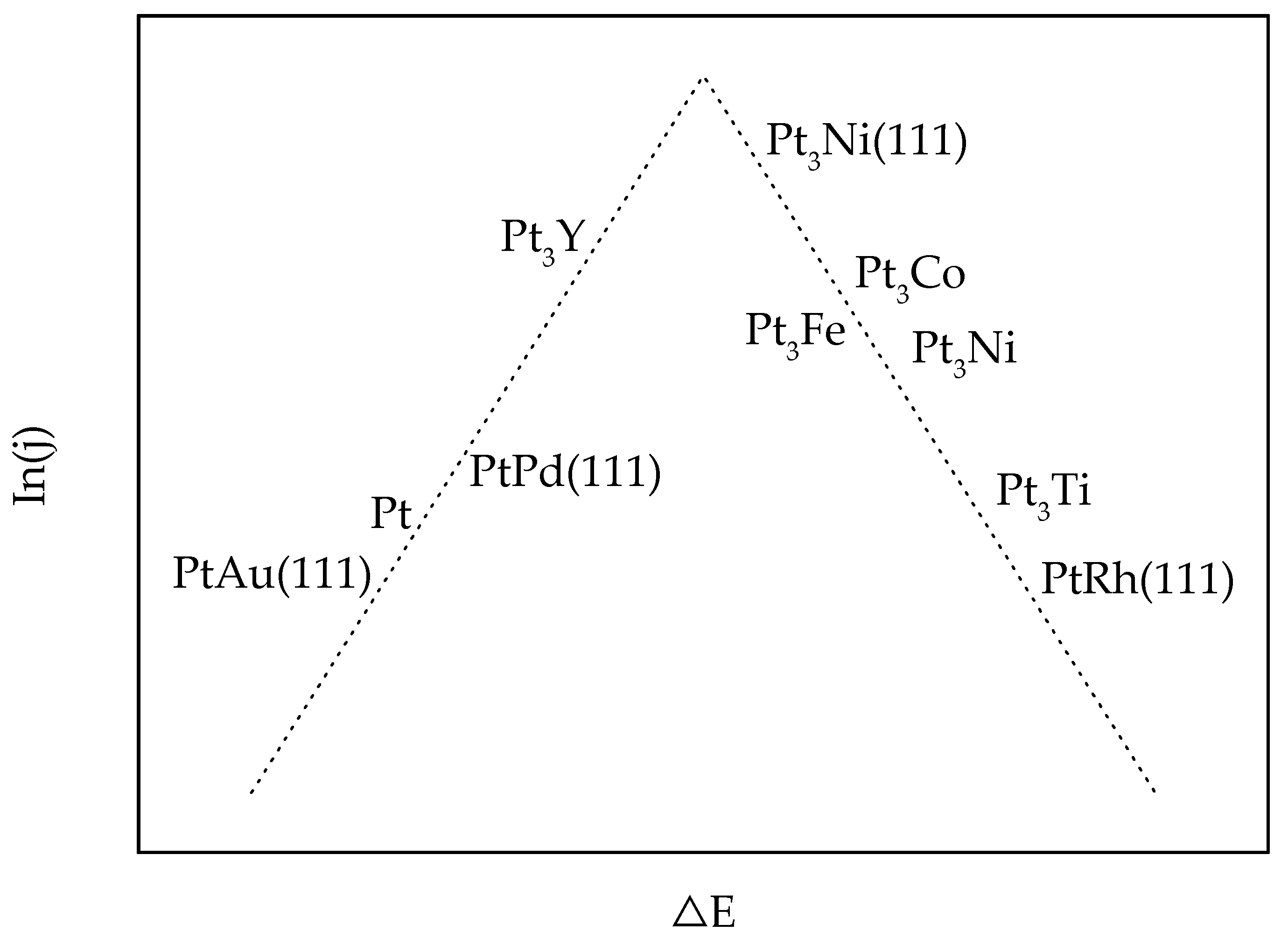
The cathode needs to use more Pt to speed up this kinetically slow reaction [3,4]. However, Pt resources on the earth are limited, and the cost of precious metal Pt catalysts accounts for more than 50% of the cost of fuel cell stacks and therefore limits the large-scale commercial application of fuel cells. In addition to cost and resource constraints, Pt catalysts also have durability problems, which are mainly reflected in the stability of PEMFCs. Through the analysis of the fuel cell degradation mechanism, it can be seen that under the operating conditions of the fuel cell, the catalyst will have problems such as agglomeration, migration, and dissolution of Pt nanoparticles, resulting in a gradual decrease in the active surface and degradation of battery performance [5,6]. In order to reduce the amount of Pt used in fuel cell catalysts, reduce costs, and extend the service life of fuel cells, the development of high-efficiency low-platinum catalysts and mass production are key technologies to accelerate the application of fuel cells [5,7]. The use of relatively inexpensive transition metals (M) to form alloys with Pt is a strategy that has attracted much attention in the development of Pt-based catalysts [8,9]. Through the formation of the alloy, not only can the Pt dosage and use cost be effectively reduced, but also the Pt active surface utilization rate can be improved. Through the influence of the metal (M) on the electronic structure of Pt, the catalytic activity of a single Pt atom can be improved [10,11]. According to Sabatier’s principle, the binding energy of reactants, reaction intermediates, or products with the catalyst should not be too strong or too weak. If the binding energy is too weak, the reactants are difficult to adsorb on the surface of the catalyst; conversely, if the binding energy is too strong, the reaction products will block the active sites on the catalyst surface, as shown in Figure 1 [12]. Either condition is bad for the reaction rate. Table 1 summarizes the ORR properties of some reported alloy-related electrocatalysts.
As nickel metal is the fifth largest metal reserve on the earth, its source is abundant and its price is low. PtNi alloy catalysts have excellent electrochemical properties, and the research about PtNi alloy catalysts has become a hot topic in the field of fuel cell catalysts in recent years. In this study, a PtNi/C catalyst with 52 wt.% metal mass fraction and a core-shell like structure was synthesized by a simple method with high temperature annealing and acid treatment. The atomic ratio of Pt to Ni was close to 1:0.6. The electrochemical test results show that the prepared PtNi/C catalyst has higher electrochemical performance than the Pt/C catalyst prepared by the same method. The ECSA of PtNi/C reached 63.8 m2·gPt−1, and the MA was 0.547 A·mgPt−1. In addition, after the 30 K-cycles accelerated durability test, ECSA of PtNi/C only decays by 10.6%, and MA only decays by 31.2%. More significant is that the preparation process used in this study is easy to repeat and thus has great commercial production potential.
2. Results and Discussion
2.1. Analysis of Physical Properties
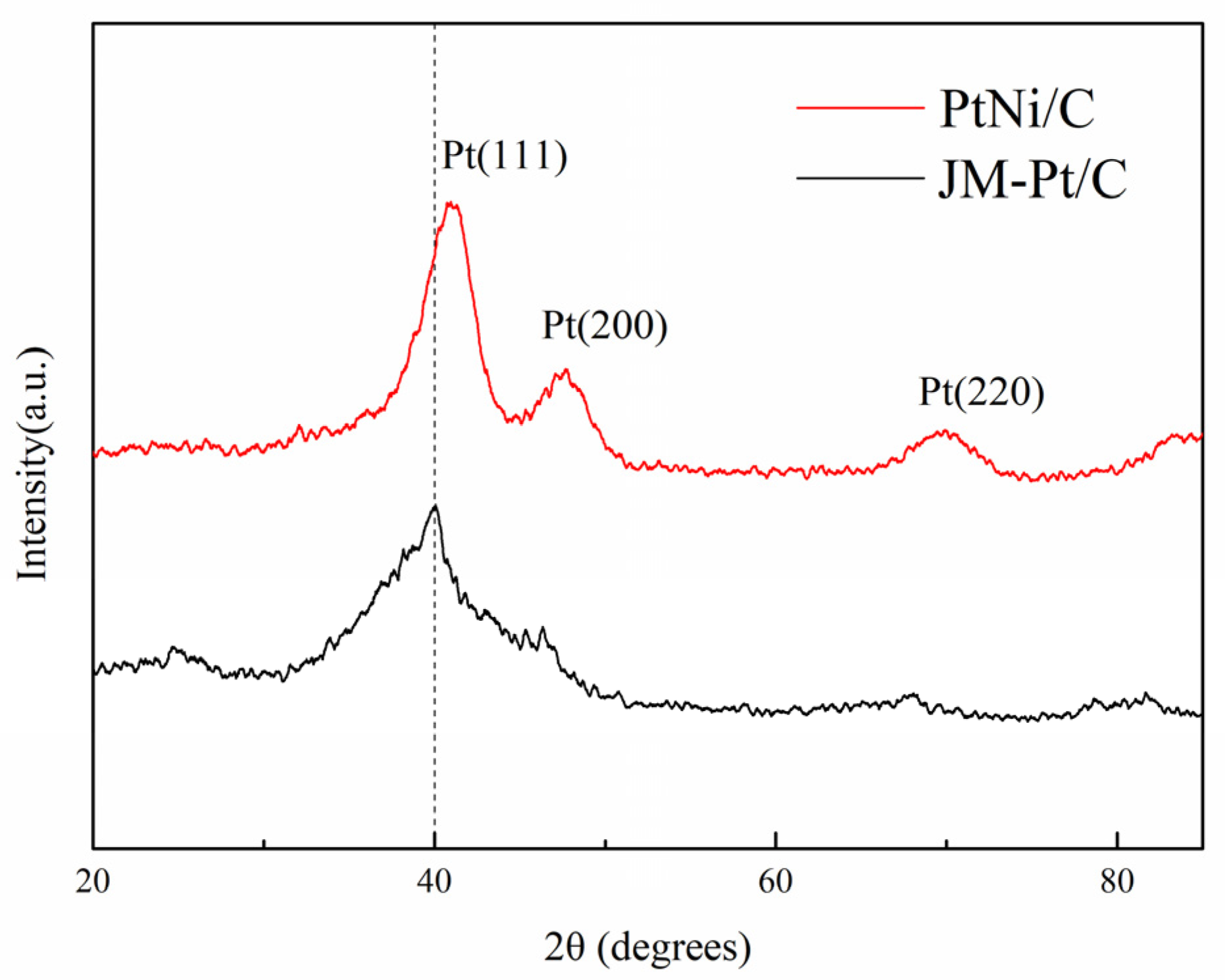
The XRD patterns of the PtNi/C nano-catalyst and the JM-Pt/C nano-catalyst are shown in Figure 2. As shown in the figure, three distinct crystallization peaks from low to high value of 2θ correspond to the Pt(111) plane, Pt(200) plane, and Pt(220) plane, respectively, indicating that the PtNi/C nano-catalyst has a face-centered cubic (fcc) structure. Compared with the diffraction peak of the JM-Pt/C catalyst, the diffraction peak of the PtNi/C catalyst has shifted to a larger angle. Because the radius of Ni atoms (1.62 Å) is smaller than the radius of Pt atoms (1.83 Å), the Pt lattice shrinks when Ni atoms enter the Pt lattice to form an alloy phase with Pt [21]. In addition, the PtNi/C catalyst shows a higher diffraction peak intensity, which indicates that the PtNi/C catalyst has excellent crystallinity. Furthermore, the decrease of full width at half maxima (FWHM) of diffraction peak also indicates the increased size of the PtNi/C catalyst. The lattice spacing of PtNi/C as calculated by Bragg’s law and Scherrer’s equation is 0.218 nm, which is significantly smaller than that of standard single crystal Pt (111) (0.226 nm). Smaller lattice spacing of PtNi/C is consistent with the shift of the XRD diffraction peak to the right, which indicates that there is a good alloying degree between Pt and Ni. The XRD results indicated this study had successfully prepared a PtNi alloy catalyst with excellent crystallinity.
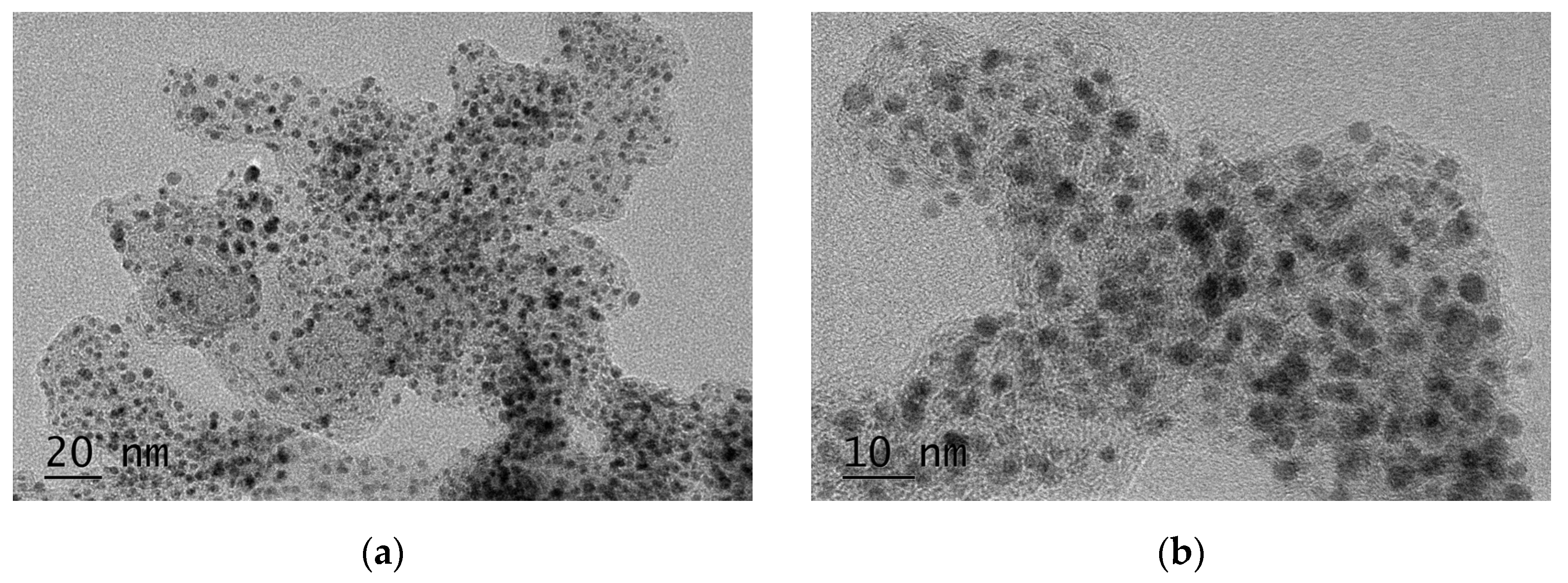
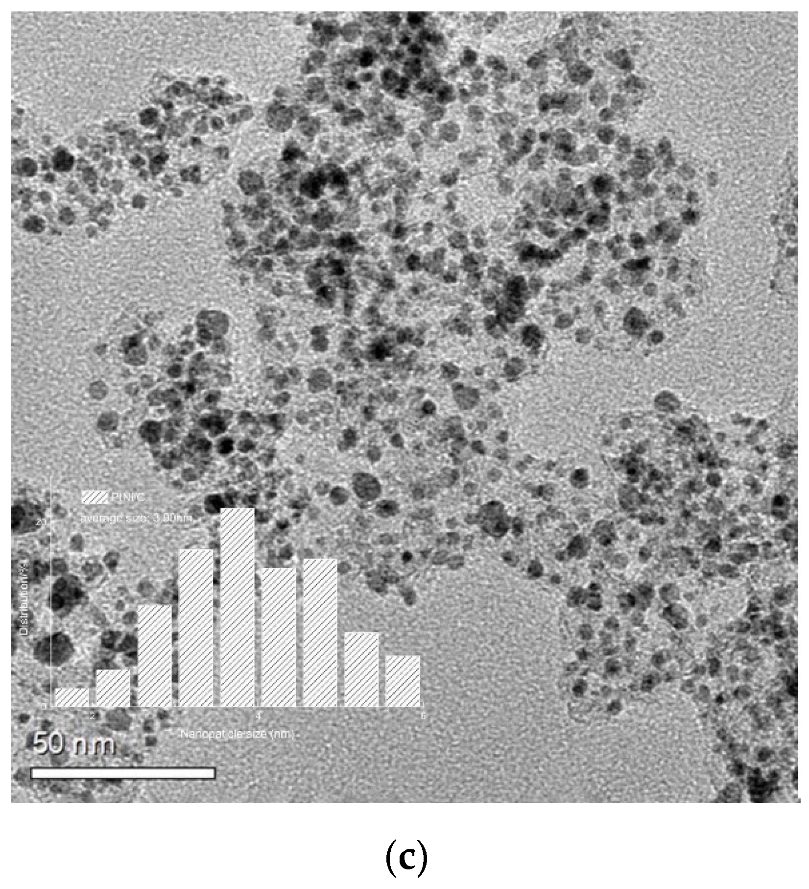
Figure 3 shows the TEM images of the PtNi/C nano-catalyst. It can be seen that the morphology of the prepared catalyst is approximately spherical. The metal particles in the PtNi/C nano-catalyst are uniformly dispersed on the carbon support, and the particle size is similar, which proves the effectiveness of the preparation process. As shown in Figure 3, the average particle size of PtNi/C nano-catalyst is 3.90 nm, calculated by randomly counting 200 particles. According to the previous studies, the particle size of PtNi/C catalyst falls in the appropriate size range that is conducive to obtain the best electrochemical performance [22]. The uniform distribution of metal particles on the carbon support also greatly improves the utilization rate of Pt. Through the analysis of TEM, it can be seen that the PtNi/C nano catalyst has the physical characteristics to be a high-performance catalyst.
The composition of the PtNi/C catalyst was analyzed by inductive coupled plasma emission spectrometer (ICP). The metal proportion is shown in Table 2. The content of Pt and Ni in the catalyst is 47 wt.% and 5 wt.%, and the atomic ratio of Pt and Ni is approximately 1:0.35. Figure 4 shows the X-ray energy dispersive spectroscopy (EDS) of PtNi/C. It was observed that the peak intensity of Pt was significantly higher than that of Ni, and the peak area of Pt was also larger, which proved that the relative content of Pt in the outer layer of the catalyst was much higher than that of Ni. The mass fraction ratio of Pt to Ni is 20.3:1, which is much larger than that of ICP. It can be inferred that the Ni of the outer layer is mostly removed by the pickling process, thus forming a Pt-rich atomic outer layer. Combined with the TEM images in Figure 2, we speculate that the PtNi/C catalyst is a kind of core-shell like structure with rich Ni in the inner layer and rich Pt in the outer layer.
2.2. Analysis of Electrochemical Performance
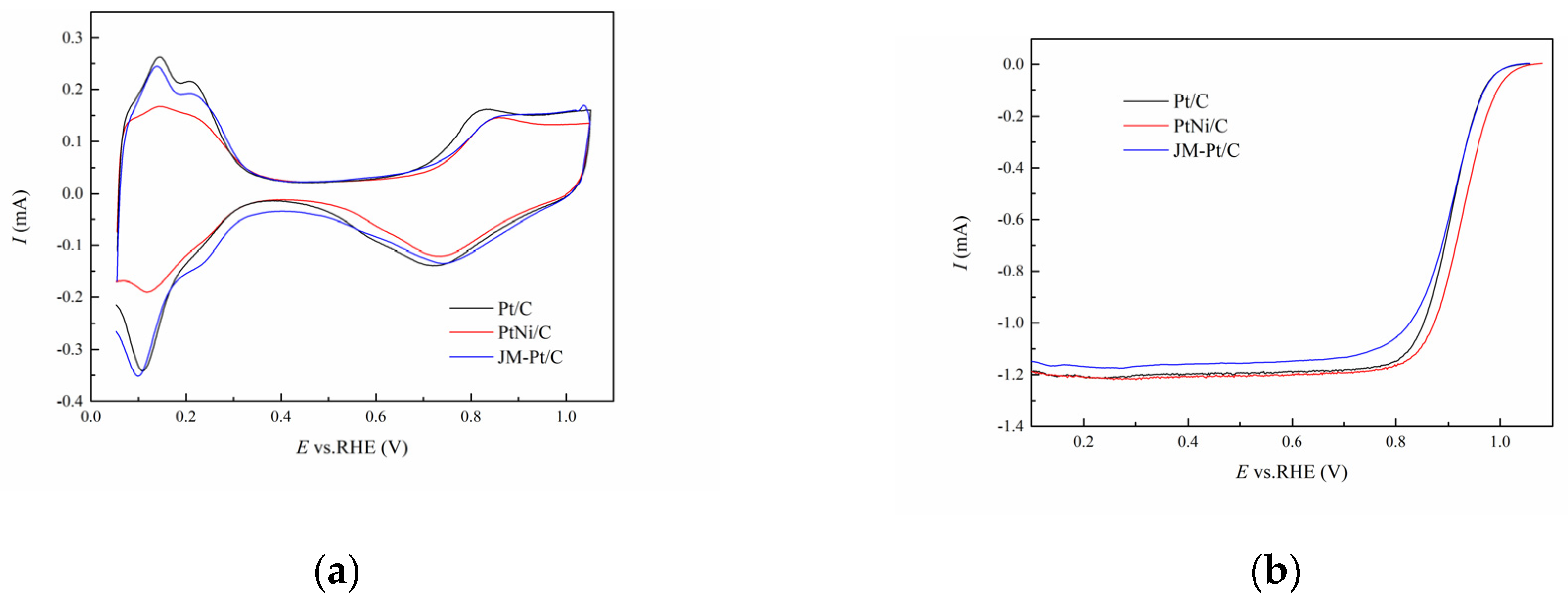
Figure 5 shows the CV and LSV curves of PtNi/C nano-catalyst, Pt/C nano-catalyst, and JM commercial catalyst (JM-Pt/C, 60 wt.% of Pt loading), respectively. It can be observed from Figure 5a that the hydrogen adsorption/desorption area of Pt/C is larger than that of the PtNi/C catalyst, because the microcrystalline size of alloy catalyst is usually larger, which reduces its electrochemical surface area (ECSA) [21,22]. However, the ORR activity of PtNi/C increased significantly due to its higher half wave potential, as can be seen from the LSV curve. According to the CV and LSV curves, we calculated the ECSA and mass activity (MA) of the three catalysts, as shown in Table 3. It can be seen that the ECSA of the PtNi/C catalyst is still slightly higher than that of the commercial JM-Pt/C catalyst, although the hydrogen adsorption/desorption area is lower than that of the commercial JM Pt/C catalyst. Furthermore, the MA of the PtNi/C catalyst is as high as 0.574 A·mgpt−1, which is approximately 2.13 times that of the Pt/C catalyst and 2.73 times that of the JM-Pt/C catalyst.
There are two reasons why the ORR performance of the PtNi/C catalyst is significantly higher than that of the Pt/C and JM Pt/C catalysts. First, the PtNi/C catalyst was pickled in the preparation process to remove the excess transition metal, so that the active sites on the Pt (111) surface were fully exposed, which was conducive to the improvement of ORR performance. Furthermore, the addition of Ni can change the atomic and electronic structure of Pt. Ni with a smaller atomic radius enters the Pt lattice, reducing the Pt-Pt lattice spacing. The outer electrons of Ni tend to transfer to Pt, which makes the 5d orbital of Pt closer to the full state and changes the position of the d-band center of Pt [9,23]. All the changes noted above are conducive to the adsorption of oxygen molecules on the crystal surface, which is conducive to enhancing the ORR activity of the catalyst [24].
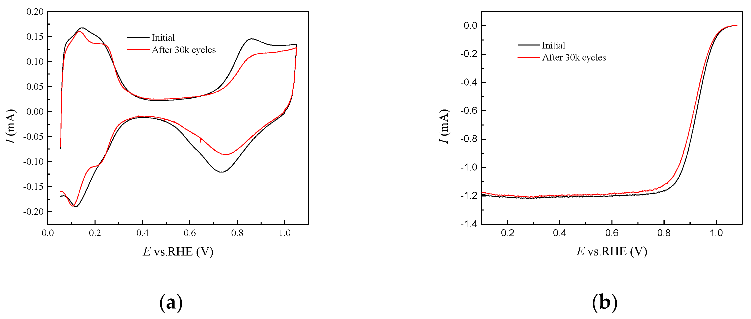
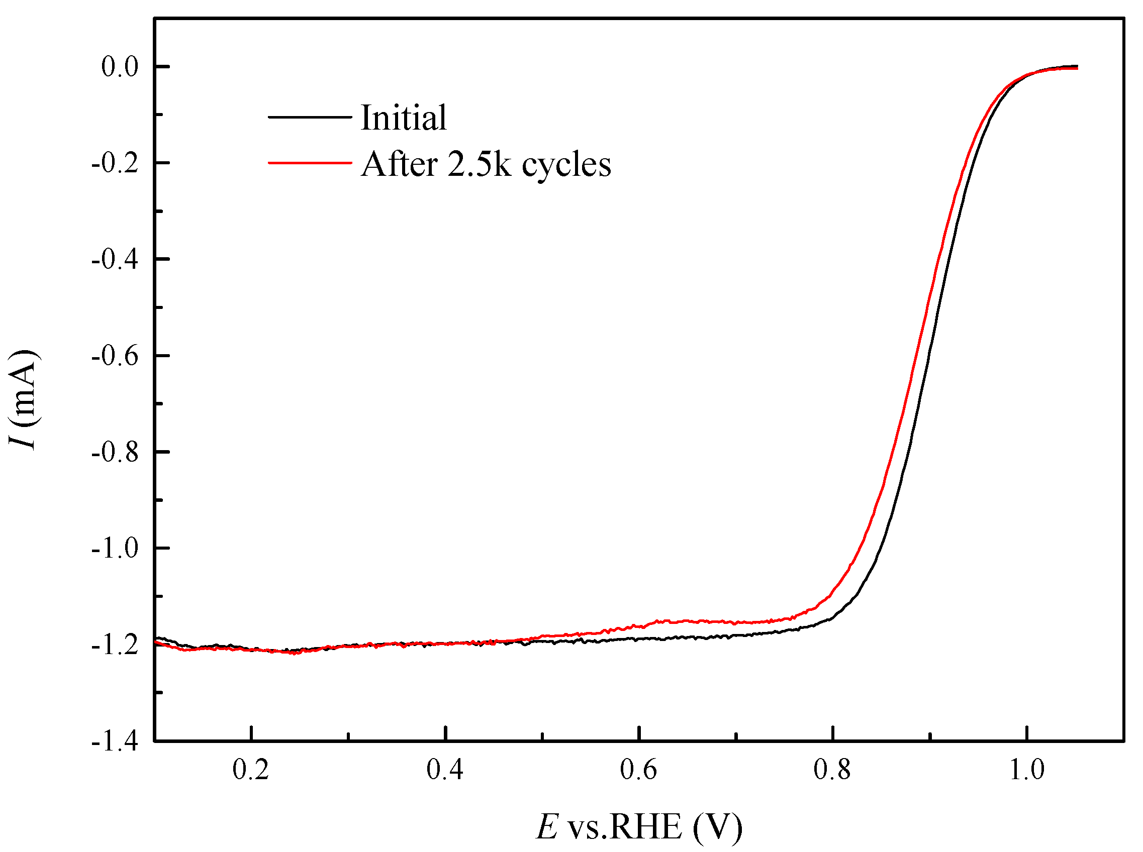
In order to further explore the durability of the PtNi/C catalyst, we carried out an accelerated durability test (ADT). The accelerated durability test was conducted in 0.1 M HClO4 solution at a scan rate of 100 mV·s−1, ranging from 0.6 to 1.0 V (vs. RHE) for 30 K cycles. The CV and LSV curves before and after the test are shown in Figure 6a,b. It can be seen that the hydrogen desorption area in the CV curve and half wave potential in the LSV curve both decreased after a 30 K cycle durability test. The ECSA of PtNi/C was calculated to be 57.0 m2·gpt−1, and the MA was calculated to be 0.395 A·mgpt−1 after the durability test, with a decrease of 10.6% and 31.2%, respectively. In contrast, the MA of the Pt/C catalyst decreased by 34.4% after only 2.5 k cycles of ADT, as shown in Figure 7.
According to the ADT results, the stability of the PtNi/C catalyst prepared in this study is much better than that of the Pt/C catalyst. Due to the pickling progress, the excess transition metal Ni on the surface of the catalyst was removed, thus forming a kind of core-shell like structure with a Pt-rich outer layer and Ni-rich inner layer. The relatively compact Pt shell on the outer layer can protect the inner Ni from leaching, thus stabilizing the crystal [25,26]. In addition, compared with the Pt/C catalyst, the PtNi/C catalyst has larger particle size that leads to the smaller specific surface area and lower surface energy, which can alleviate the agglomeration of nanoparticles to a certain extent and thus improve the stability of the catalyst.
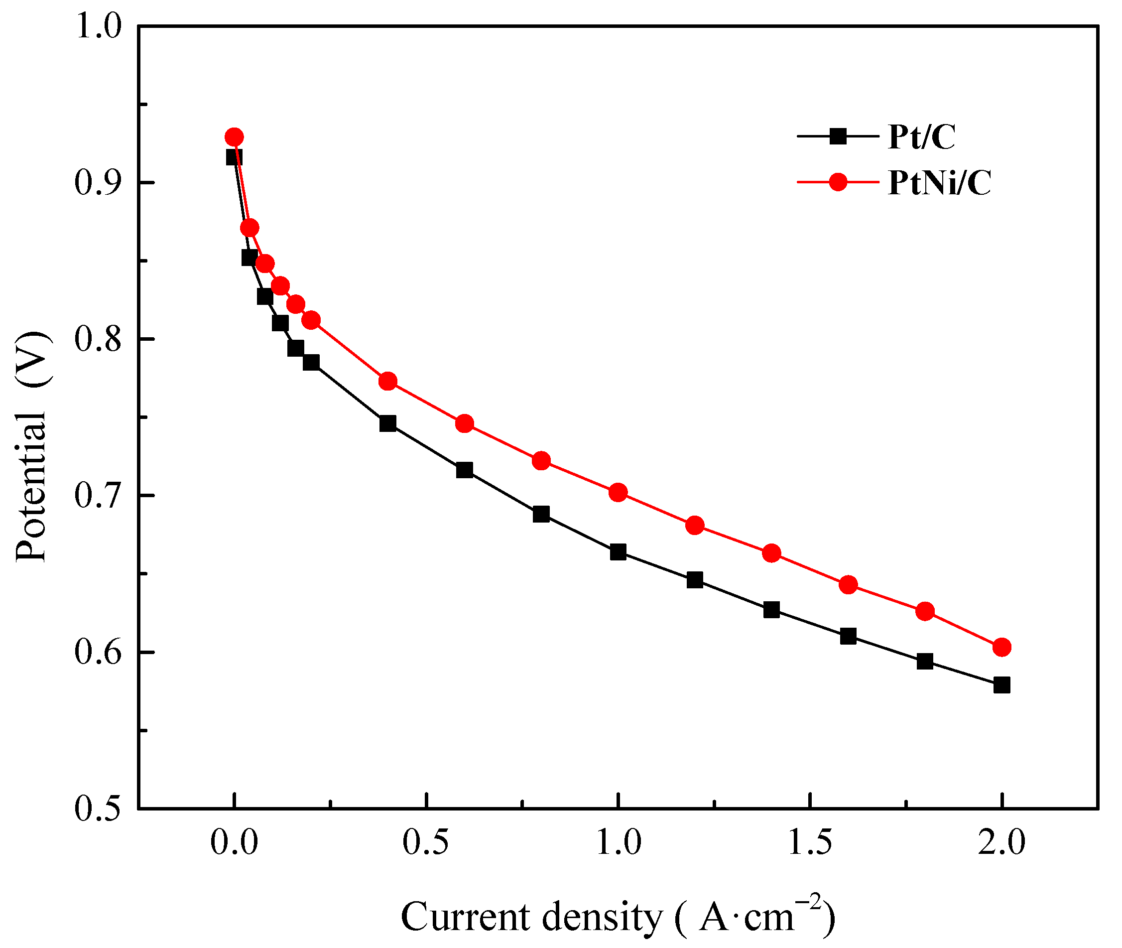
It can be seen from Figure 8 that the performance of the PtNi/C nano-catalyst in the single cell test is better than that of the JM commercial catalyst, which is consistent with the results of the rotating disc electrode test. The open circuit potentials of the PtNi/C nano-catalyst and the commercial JM-Pt/C catalyst are 0.929 V and 0.916 V, respectively. The power density at 0.65 V of PtNi/C and JM-Pt/C were 1.022 w·cm−2 and 0.775 w·cm−2, respectively. Compared with the JM-Pt/C catalyst, the performance of the membrane electrode prepared by the PtNi/C nano-catalyst was improved by 32%. The results of the single cell test show that PtNi/C can also exhibit good activity in the actual fuel cell membrane electrode operating environment.
3. Materials and Methods
3.1. Materials
The H2PtCl·6H2O and NiCl2·6H2O were from Kunming Boren Precious Metals Co., Ltd. The NaOH, C2H6O2, Ni(NO3)2, C2H6O, and H2SO4 were from Sinopharm Chemical Reagent Co., Ltd. (Beijing, China). Commercial 60 wt.% Pt/C catalyst was from Johnson Matthey. The N2/H2 was from Nanjing Shangyuan Gas Co., Ltd. (Nanjing, China). The ECP600 conductive carbon black was from Shanghai Triquo Co., Ltd. (Nanjing, China).
3.2. Preparation of PtNi/C Catalyst
The mixed solvent of ethylene glycol and ultrapure water was slowly added into carbon black. The mixture of chloroplatinic acid (2 wt.%), nickel chloride (1 wt.%), and sodium hydroxide (10 wt.%) was then added, and then the mixture was stirred and impregnated. Next, the mixture was placed into a microwave reactor to react to 132 °C, cooled to about 90 °C, and removed. After standing for 10 min, the PtNi/C precursor was obtained by filtration, washing, and drying. We added 0.1 g of PtNi/C precursor prepared in the above steps into the mixed solvent of 2 mL ultra-pure water and 8 mL analytical pure ethanol and dispersed it uniformly by ultrasound. Next, Ni(NO3)2 solution was added and ultrasonically impregnated for 20 min. It was then evaporated to a smooth consistency in an oil bath at 60 °C. After that, it was removed and dried at the same temperature. The dry precursor was ground and placed into a high temperature tubular furnace, and then reduced with 5 vol% hydrogen nitrogen mixture to obtain the crude PtNix/C catalyst. The crude PtNix/C catalyst was collected, added into 100 mL sulfuric acid solution, stirred in an oil bath at 80 °C for 24 h, then washed, filtered, and dried. Finally, the PtNi/C alloy nano electrocatalyst with 52% wt. metal was obtained, in which the mass fraction of Pt was about 47 wt.%, and the mass fraction of Ni was about 5 wt.%.
The mixed solvent of ethylene glycol and ultrapure water was slowly added into the carbon black, the mixture of chloroplatinic acid (2 wt.%) and sodium hydroxide (10 wt.%) was added, and then the mixture was stirred and impregnated. The mixture was then placed in the microwave reactor to react to 132 °C, cooled to about 90 °C, and removed. After standing for 10 min, the catalyst was filtered, washed, and dried, and marked as Pt/C.
3.3. Physical Characterization of Catalyst
The crystal structure, morphology, and physical properties of the PtNi/C alloy nano-catalyst were characterized by inductively coupled plasma atomic emission spectrometry (ICP, avio500), transmission electron microscopy (TEM, TECNAI F20), energy dispersive X-ray spectroscopy (EDS), and X-ray diffraction (XRD, Bruker D8 adavance, Karlsruhe, Germany).
3.4. Electrochemical Test
An appropriate amount of Al2O3 powder (0.05 μm) was used to polish the surface of the glassy carbon electrode, after which it was rinsed with absolute ethanol and ultrapure water until there was no Al2O3 powder residue on the surface. Next, 2 mg of the sample and 1600 μL of ethanol were added into the centrifuge tube. After sonicating for 3 min, 400 μL of ultrapure water droplets was added into the centrifuge tube. We then added 14.2 μL Nafion (5 wt.%, Cobot, Boston, MA USA) into the mixed solution. After 30 min of ultrasound, 5 ul of the mixed slurry was dropped onto the surface of the processed glassy carbon electrode (d = 5 mm) and dried under an incandescent lamp to form a film. We then dropped 5 μL of the slurry on the formed glassy carbon electrode. Once on the electrode, it was dried again under an incandescent lamp to form a film.
After the film was dried, the electrochemical test and related data were recorded by reference 3000 electrochemical workstation from Gamry company. The standard three electrode system was used to test the cyclic voltammetry curve to calculate the electrochemical active area (ECSA), and linear sweep voltammetry was used to determine the oxygen reduction capacity. The standard hydrogen electrode was selected as the reference electrode, the platinum wire was used as the working electrode, and the electrolyte was 0.1 M HClO4 aqueous solution.
Before the cyclic voltammetry (CV) curve was tested, high purity nitrogen was introduced until the nitrogen in the hydrogen chloride electrolyte was saturated. The cyclic voltammetry test was then carried out. For the activation process, the electrochemical workstation scanning potential was 0.05~1.2 V (vs. RHE), the scanning speed was 200 mV/s, and the number of scanning cycles was 20 cycles. For the CV test process, the potential interval was 0.05~1.05 V (vs. RHE), and the scanning speed was 50 mV/s. After the cyclic voltammetry test, we passed high purity oxygen into the electrolyte HCLO4 aqueous solution until the electrolyte was saturated with oxygen, and we then performed a linear voltammetry curve test. The sweep potential was 0.6~1.0 V (vs. RHE), and the electrode rotation speed was 1600 rpm. For the accelerated durability test (ADT), under the condition of 0.1 M nitrogen saturated with HCLO4 solution, the sweep potential was 0.6~1.0 V (vs. RHE), the sweep speed was 100 mV/s, and the scan was 30 K circles.
3.5. Single Cell Test Process and Method
The membrane electrode with an ultrasonic area of 25 cm2 was prepared by a catalyst coating method. First, the catalyst was dissolved in a mixture of ultrapure water, isopropanol, and Nafion. The total ratio of Nafion to carbon in the slurry was maintained at 0.7. The slurry was then ultrasonically treated until there was no particle precipitation. Two gas diffusion layers with the thickness of 0.234 mm were placed on both sides of the anode and cathode catalyst layer. Polytetrafluoroethylene was used in the gas diffusion layer for hydrophobicity. Finally, a suitable gasket was fitted, and we then assembled the two graphite plates with flow channels to the membrane.
4. Conclusions
In this study, a PtNi alloy catalyst with good alloying degree and high metal loading was prepared by a simple method. Due to its special core-shell like structure and synergistic effect between alloys, the PtNi/C nano-catalyst showed excellent electrochemical performance. The ECSA of PtNi/C reached 63.8 m2·gPt−1, and the MA reached 0.574 A·mgPt−1. The MA of the PtNi/C nano-catalyst is far beyond the 2020 target set by the U.S. Department of Energy for Pt based catalysts for automotive fuel cells (0.44 A·mgpt−1). The PtNi/C nano-catalyst also showed excellent stability. ECSA and MA of PtNi/C only decreased by 10.2% and 31.2%, respectively, after ADT with 30 K cycles. Furthermore, in the single cell test, the membrane electrode prepared by PtNi/C nano-catalyst also exhibited excellent performance. Combined with the above advantages, the PtNi/C alloy catalyst prepared in this study can effectively improve the catalytic activity and stability of PEMFCs, and thus improve the utilization rate of Pt. Ultimately, the cost of PEMFCs is fundamentally reduced. In addition, the metal loading of the PtNi/C alloy catalyst prepared in this study reaches 52 wt.%, which meets the requirements of industrial production for high metal loading of catalysts and has great potential for large-scale commercial application.
Author Contributions
Conceptualization, J.G. and R.Y.; methodology, J.G. and R.Y.; formal analysis, J.G., R.Y. and M.-F.H.; investigation, G.-M.Z.; writing—original draft preparation, R.Y.; writing—review and editing, R.Y. and M.-F.H.; supervision, J.G., T.Y. and R.-S.H.; project administration, J.G. All authors have read and agreed to the published version of the manuscript.
Funding
This research was funded by the Fundamental Research Funds for the Central Universities, grant number 020414380168. The research was supported by “2021 Nantong Municipal Basic Science Research Project, JC2021109”.
Conflicts of Interest
The authors declare no conflict of interest.
References
- Wee, J.-H.; Lee, K.-Y.; Kim, S.H. Fabrication methods for low-Pt-loading electrocatalysts in proton exchange membrane fuel cell systems. J. Power Sources 2007, 165, 667–677. [Google Scholar] [CrossRef]
- Zhang, L.; Zhang, J.; Wilkinson, D.P.; Wang, H. Progress in preparation of non-noble electrocatalysts for PEM fuel cell reactions. J. Power Sources 2006, 156, 171–182. [Google Scholar] [CrossRef]
- Brandon, N.P.; Skinner, S.; Steele, B.C.H. Recent Advances in Materials for Fuel Cells. Annu. Rev. Mater. Res. 2003, 33, 183–213. [Google Scholar] [CrossRef]
- Gasteiger, H.A.; Kocha, S.S.; Sompalli, B.; Wagner, F.T. Activity benchmarks and requirements for Pt, Pt-alloy, and non-Pt oxygen reduction catalysts for PEMFCs. Appl. Catal. B Environ. 2005, 56, 9–35. [Google Scholar] [CrossRef]
- Chaudhari, N.K.; Joo, J.; Kim, B.; Ruqia, B.; Choi, S.I.; Lee, K. Recent advances in electrocatalysts toward the oxygen reduction reaction: The case of PtNi octahedra. Nanoscale 2018, 10, 20073–20088. [Google Scholar] [CrossRef] [PubMed]
- Nie, Y.; Li, L.; Wei, Z. Recent advancements in Pt and Pt-free catalysts for oxygen reduction reaction. Chem. Soc. Rev. 2015, 44, 2168–2201. [Google Scholar] [CrossRef] [PubMed]
- Yao, R.; Gu, J.; He, H.; Yu, T. Improved Electrocatalytic Activity and Durability of Pt Nanoparticles Supported on Boron-Doped Carbon Black. Catalysts 2020, 10, 862. [Google Scholar] [CrossRef]
- Stamenkovic, V.R.; Fowler, B.; Mun, B.S.; Wang, G.; Ross, P.N.; Lucas, C.A.; Marković, N.M. Improved Oxygen Reduction Activity on Pt3Ni(111) via Increased Surface Site Availability. Science 2007, 315, 493–497. [Google Scholar] [CrossRef] [Green Version]
- Wang, C.; Chi, M.; Wang, G.; van der Vliet, D.; Li, D.; More, K.; Wang, H.-H.; Schlueter, J.A.; Markovic, N.M.; Stamenkovic, V.R. Correlation Between Surface Chemistry and Electrocatalytic Properties of Monodisperse PtxNi1-x Nanoparticles. Adv. Funct. Mater. 2011, 21, 147–152. [Google Scholar] [CrossRef]
- Wang, C.; Markovic, N.M.; Stamenkovic, V.R. Advanced Platinum Alloy Electrocatalysts for the Oxygen Reduction Reaction. ACS Catal. 2012, 2, 891–898. [Google Scholar] [CrossRef]
- Yu, Z.; Zhang, J.; Liu, Z.; Ziegelbauer, J.M.; Xin, H.; Dutta, I.; Muller, D.A.; Wagner, F.T. Comparison between Dealloyed PtCo3 and PtCu3 Cathode Catalysts for Proton Exchange Membrane Fuel Cells. J. Phys. Chem. C 2012, 116, 19877–19885. [Google Scholar] [CrossRef]
- Xia, W.; Mahmood, A.; Liang, Z.; Zou, R.; Guo, S. Earth-Abundant Nanomaterials for Oxygen Reduction. Angew. Chem. Int. Ed. Engl. 2016, 55, 2650–2676. [Google Scholar] [CrossRef] [PubMed]
- Zhang, B.-W.; Zhang, Z.-C.; Liao, H.-G.; Gong, Y.; Gu, L.; Qu, X.-M.; You, L.-X.; Liu, S.; Huang, L.; Tian, X.-C.; et al. Tuning Pt-skin to Ni-rich surface of Pt3Ni catalysts supported on porous carbon for enhanced oxygen reduction reaction and formic electro-oxidation. Nano Energy 2016, 19, 198–209. [Google Scholar] [CrossRef]
- Tzorbatzoglou, F.; Brouzgou, A.; Jing, S.; Wang, Y.; Song, S.; Tsiakaras, P. Oxygen reduction and hydrogen oxidation reaction on novel carbon supported Pd x Ir y electrocatalysts. Int. J. Hydrogen Energy 2018, 43, 11766–11777. [Google Scholar] [CrossRef]
- Stamenkovic, V.R.; Mun, B.S.; Arenz, M.; Mayrhofer, K.J.; Lucas, C.A.; Wang, G.; Ross, P.N.; Markovic, N.M. Trends in electrocatalysis on extended and nanoscale Pt-bimetallic alloy surfaces. Nat. Mater. 2007, 6, 241–247. [Google Scholar] [CrossRef]
- Matin, M.A.; Lee, J.; Kim, G.W.; Park, H.-U.; Cha, B.J.; Shastri, S.; Kim, G.; Kim, Y.-D.; Kwon, Y.-U.; Petkov, V. Morphing Mncore@Ptshell nanoparticles: Effects of core structure on the ORR performance of Pt shell. Appl. Catal. B Environ. 2020, 267, 118727. [Google Scholar] [CrossRef]
- Kwon, T.; Jun, M.; Kim, H.Y.; Oh, A.; Park, J.; Baik, H.; Joo, S.H.; Lee, K. Vertex-Reinforced PtCuCo Ternary Nanoframes as Efficient and Stable Electrocatalysts for the Oxygen Reduction Reaction and the Methanol Oxidation Reaction. Adv. Funct. Mater. 2018, 28, 1706440. [Google Scholar] [CrossRef]
- Jiang, K.; Shao, Q.; Zhao, D.; Bu, L.; Guo, J.; Huang, X. Phase and Composition Tuning of 1D Platinum-Nickel Nanostructures for Highly Efficient Electrocatalysis. Adv. Funct. Mater. 2017, 27, 1700830. [Google Scholar] [CrossRef]
- Liu, Y.; Chen, H.; Tian, C.; Geng, D.; Wang, D.; Bai, S. One-Pot Synthesis of Highly Efficient Carbon-Supported Polyhedral Pt3Ni Alloy Nanoparticles for Oxygen Reduction Reaction. Electrocatalysis 2019, 10, 613–620. [Google Scholar] [CrossRef]
- Li, X.; Liu, Y.; Zhu, J.; Tsiakaras, P.; Shen, P.K. Enhanced oxygen reduction and methanol oxidation reaction over self-assembled Pt-M (M = Co, Ni) nanoflowers. J. Colloid Interface Sci. 2022, 607, 1411–1423. [Google Scholar] [CrossRef]
- Wang, J.; Li, B.; Yang, D.; Lv, H.; Zhang, C. Preparation optimization and single cell application of PtNi/C octahedral catalyst with enhanced ORR performance. Electrochim. Acta 2018, 288, 126–133. [Google Scholar] [CrossRef]
- Nesselberger, M.; Ashton, S.; Meier, J.C.; Katsounaros, I.; Mayrhofer, K.J.; Arenz, M. The particle size effect on the oxygen reduction reaction activity of Pt catalysts: Influence of electrolyte and relation to single crystal models. J. Am. Chem. Soc. 2011, 133, 17428–17433. [Google Scholar] [CrossRef] [PubMed]
- Antolini, E.; Salgado, J.R.C.; Gonzalez, E.R. The stability of Pt–M (M=first row transition metal) alloy catalysts and its effect on the activity in low temperature fuel cells. J. Power Sources 2006, 160, 957–968. [Google Scholar] [CrossRef]
- Wang, C.; Chi, M.; Li, D.; Strmcnik, D.; van der Vliet, D.; Wang, G.; Komanicky, V.; Chang, K.C.; Paulikas, A.P.; Tripkovic, D.; et al. Design and synthesis of bimetallic electrocatalyst with multilayered Pt-skin surfaces. J. Am. Chem. Soc. 2011, 133, 14396–14403. [Google Scholar] [CrossRef] [PubMed]
- Han, B.; Carlton, C.E.; Kongkanand, A.; Kukreja, R.S.; Theobald, B.R.; Gan, L.; O’Malley, R.; Strasser, P.; Wagner, F.T.; Shao-Horn, Y. Record activity and stability of dealloyed bimetallic catalysts for proton exchange membrane fuel cells. Energy Environ. Sci. 2015, 8, 258–266. [Google Scholar] [CrossRef]
- Kumeda, T.; Kimura, H.; Hoshi, N.; Nakamura, M. Activity for the oxygen reduction reaction of the single crystal electrode of Ni modified with Pt. Electrochem. Commun. 2016, 68, 15–18. [Google Scholar] [CrossRef]
Figure 1.
Volcanic distribution of ORR activity of Pt-based transition-metal alloys.

Figure 2.
XRD patterns of PtNi/C and JM-Pt/C.

Figure 3.
TEM images of PtNi/C. (a–c) are the TEM images of PtNi/C at different magnification.


Figure 4.
Energy dispersion X-ray spectrogram of PtNi/C.

Figure 5.
CV (a) and LSV(b) curves of PtNi/C, JM-Pt/C, and Pt/C.

Figure 6.
CV (a) and LSV (b) curves of PtNi/C before and after ADT.

Figure 7.
LSV curves of Pt/C before and after ADT.

Figure 8.
The single cell performance curves of PtNi/C and JM-Pt/C catalysts.


Table 1.
Summary of the electrochemical performances of recently reported alloy-related electrocatalysts for the ORR.
Table 1.
Summary of the electrochemical performances of recently reported alloy-related electrocatalysts for the ORR.
| Catalyst | ECSA (m2·gPt−1) | MA (A·mgPt−1) | Electrolyte |
|---|---|---|---|
| Pt3Ni/PC (Pt-skin) [13] | — — | 0.69 | 0.1 M HClO4 |
| PdIr/C [14] | 270 | 0.1 M HClO4 | |
| Pt3Co/C [15] | 30 | 1.3 | 0.1 M HClO4 |
| Mn@2Pt/C [16] | 112.3 | 1.1 | 0.1 M HClO4 |
| Co-PrCu RNFs [17] | 31 | 1.56 | 0.1 M HClO4 |
| Pt3Ni NWs [18] | 43.8 | 5.60 | 0.1 M HClO4 |
| Pt3Ni/C [19] | 11.2 | 0.16 | 0.1 M HClO4 |
| Pt-Co GND/C [20] | 137.1 | 2.041 | 0.1 M HClO4 |
— — means the data is not mentioned in the article.
Table 2.
Metal composition of PtNi/C from ICP.
| Metal | Ratio (wt.%) |
|---|---|
| Pt | 47 |
| Ni | 5 |
Table 3.
ECSA and MA parameters of PtNi/C Pt/C, and JM-Pt/C catalysts.
| Catalysts | ECSA (m2·gPt−1) | MA (A·mgPt−1) |
|---|---|---|
| PtNi/C | 63.8 | 0.574 |
| Pt/C | 79.2 | 0.270 |
| JM-Pt/C | 60.2 | 0.210 |
Publisher’s Note: MDPI stays neutral with regard to jurisdictional claims in published maps and institutional affiliations. |
© 2022 by the authors. Licensee MDPI, Basel, Switzerland. This article is an open access article distributed under the terms and conditions of the Creative Commons Attribution (CC BY) license (https://creativecommons.org/licenses/by/4.0/).
Share and Cite
MDPI and ACS Style
Gu, J.; Zhang, G.-M.; Yao, R.; Yu, T.; Han, M.-F.; Huang, R.-S. High Oxygen Reduction Activity of Pt-Ni Alloy Catalyst for Proton Exchange Membrane Fuel Cells. Catalysts 2022, 12, 250. https://0-doi-org.brum.beds.ac.uk/10.3390/catal12030250
AMA Style
Gu J, Zhang G-M, Yao R, Yu T, Han M-F, Huang R-S. High Oxygen Reduction Activity of Pt-Ni Alloy Catalyst for Proton Exchange Membrane Fuel Cells. Catalysts. 2022; 12(3):250. https://0-doi-org.brum.beds.ac.uk/10.3390/catal12030250
Chicago/Turabian StyleGu, Jun, Guang-Meng Zhang, Rui Yao, Tao Yu, Meng-Fei Han, and Run-Sheng Huang. 2022. "High Oxygen Reduction Activity of Pt-Ni Alloy Catalyst for Proton Exchange Membrane Fuel Cells" Catalysts 12, no. 3: 250. https://0-doi-org.brum.beds.ac.uk/10.3390/catal12030250
Note that from the first issue of 2016, this journal uses article numbers instead of page numbers. See further details here.