Article

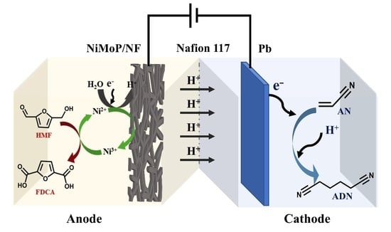
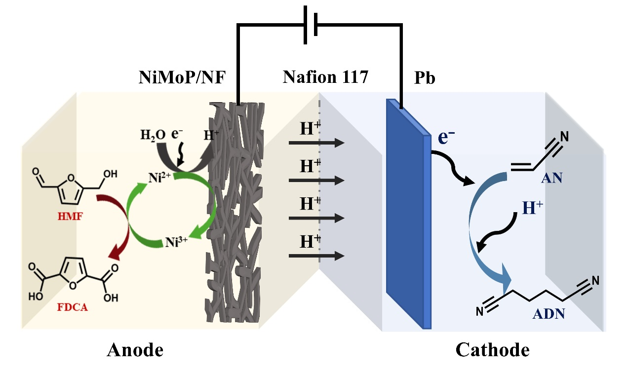
Paired Electrolysis of Acrylonitrile and 5-Hydroxymethylfurfural for Simultaneous Generation of Adiponitrile and 2,5-Furandicarboxylic Acid

Laboratory of Advanced Materials and Catalytic Engineering, State Key Laboratory of Fine Chemicals, School of Chemical Engineering, Dalian University of Technology, Dalian 116024, China
*
Author to whom correspondence should be addressed.
Submission received: 6 June 2022 / Revised: 20 June 2022 / Accepted: 21 June 2022 / Published: 24 June 2022
(This article belongs to the Special Issue Electrocatalysts for Oxidation-Reduction Reactions)

Abstract

:
The classic acrylonitrile (AN) electrohydrodimerization (EHD) to adiponitrile (ADN) process produces oxygen on the anode side. The oxygen evolution reaction (OER) is energy consuming, and O2 is of low value and has security issues while directly contacting with organic molecules. Herein, by replacing OER with 5-hydroxymethylfurfural oxidation reaction (HMFOR), we report paired electrolysis of AN and HMF for simultaneous generation of ADN and 2,5-furandicarboxylic acid (FDCA). On the anode side, the electrodeposited amorphous NiMoP film-covered nickel foam efficiently boosted HMFOR activity by enlarging the electrochemically active surface area (ECSA) via in situ selective removal of Mo and P on the surface. On the cathode side, addition of dimethylformamide (DMF) as a cosolvent enhanced the reaction efficiency of ANEHD by forming a single-phase electrolyte that offers better interaction between AN and the electrode. The ANEHD–HMFOR paired system shows excellent generation rates of FDCA (0.018 gFDCA·h−1·cm−2) and ADN (0.017 gADN·h−1·cm−2) at a high cell current (160 mA). An amount of 1 kWh of electricity can produce 2.91 mol of ADN and 0.53 mol of FDCA with 107.1% Faraday efficiency.

Graphical Abstract

1. Introduction

In recent years, with the increasing proportion of clean energy in the energy supply system, the production of chemicals by electricity-driven electrosynthesis has garnered growing attention. Among many organic electrosynthesis processes, electrocatalytic hydrodimerization of acrylonitrile (AN) to adiponitrile (ADN), a monomer of nylon 66 polymer, is a major industrialized process with an ADN annual output of more than 1 million tons [1]. For this redox reaction process, a large number of previous studies have focused on the electrochemical system with water oxidation as the anode reaction and electrocatalytic hydrodimerization of AN as the cathode reaction. An advantage of this reaction system is that the anode reaction substrate is the water solvent itself, which is remarkably simple and convenient. However, the standard potential for the oxygen evolution reaction (OER) at the anode is as high as 1.23 V [2], and even the most advanced electrocatalysts currently require an overpotential of 0.35–0.4 V to achieve current densities greater than 50 mA cm−2. Given that oxygen can be easily acquired by the air separation method, the energy consumption of the present reaction system is predominantly utilized in the production of oxygen with little economic value. Therefore, in order to fundamentally improve the economic feasibility of the reaction and reduce energy consumption, creating a completely new reaction system by replacing the anode reaction of the electrolytic cell is an effective strategy.
In the search for a suitable anode reaction, we noticed that water-soluble 5-hydroxymethylfurfural (HMF) produced by glucose (a downstream product of lignin biomass [3]) dehydration [4] could be selectively oxidized to 2,5-furandicarboxylic acid (FDCA). As a crucial renewable polymer monomer to replace petroleum-based terephthalic acid, FDCA might polymerize into poly(ethylene 2,5-furandicarboxylate) (PEF), which is regarded as a substitute for petroleum-based polyethylene terephthalate (PET) [5]. The standard electrode potential for selective oxidation of HMF to FDCA is 0.3 V, which is 0.93 V lower than that of OER (E° = 1.23 V), indicating HMFOR consumes less energy than OER [6]. The conventional method for converting HMF to FDCA is a thermocatalytic process using a noble metal (e.g., Pt, Pd, and Au) as catalysts and high-pressure (0.3~2.0 Mpa) molecular oxygen as an oxidant with water as a by-product under high operating temperature (30–130 °C) [5]. An early study explored the electrocatalytic selective oxidation of HMF employing Pd and Au electrocatalysts at varied applied potentials to make the reaction conditions milder and simplify the catalyst recovery procedure [7]. In order to reduce the cost of catalytic materials, other research teams subsequently adopted a series of nonprecious metal catalysts, such as Ni2P [8], Co–P [9], and NiFe LDH [5], to realize the HMF oxidation reaction (HMFOR). After that, research scientists began to study the reaction pathway and mechanism of HMFOR using in situ sum frequency generation vibrational spectroscopy [10], in situ Fourier-transform infrared spectroscopy [11], and operando Raman spectroscopy [12]. Recent research works have attempted to simultaneously produce FDCA and hydrogen by replacing the oxygen evolution reaction in the overall water splitting reaction with the HMF selective oxidation reaction, which effectively improves the efficiency of the electrosynthesis reaction [13]. In order to further enhance the added value of products generated by unit energy consumption and improve catalytic efficiency and electron economy, this paper proposes to couple HMFOR with AN hydrodimerization to construct a new paired electrolysis system (Scheme 1). Previous researchers have tried to couple HMF oxidation to FDCA with HMF reduction to 2,5-bis(hydroxymethyl)furan (BHMF) [14]. However, due to the substrate concentration and the electrode activity issues, the cell current is just around 10 mA, suggesting that it is still challenging to improve the efficiency of the entire catalytic system.
Due to the above-mentioned problems, this work studied a paired electrolysis reaction system with electrodeposited NiMoP amorphous film-covered nickel foam as the anode electrode. Under applied potential, the surface layer of this precatalyst is oxidized to NiOOH, which is the active species for HMF oxidation. During this in situ oxidation process, the Mo and P elements on the surface are partially removed, which enhances electrode surface roughness. In addition, this work improves the solubility of ADN by adding DMF as a cosolvent to the cathode chamber. The formed single-phase solution provides better mass transfer for AN hydrodimerization. The catalytic efficiencies of the anode and cathode were improved by the above two methods, respectively. In the paired electrolysis system, when 1440 C of electrons passed through the system under constant current condition, the anode and cathode achieved 83.7% FDCA yield and 62.3% ADN yield, respectively, while the Faraday efficiency of the whole cell reached 107.1%. On the anode side of this paired electrolysis system, the efficient HMFOR can be attributed to the surface roughness caused by the selective removal of Mo and P from the electrode surface, leading to a larger electrochemically active surface area. Meanwhile, the highly conductive framework inside the catalytic material reduces the internal resistance for electron transfer. On the cathode side, the addition of cosolvents boosts the degree of contact between the substrate and the electrode surface. Since the cathode and anode simultaneously increase the conversion rate of substrate molecules, the paired electrolysis system can achieve simultaneous generation of FDCA and ADN at high current (160 mA). After calculation, 1 kWh of electricity can produce 2.91 mol of ADN and 0.53 mol of FDCA.

2. Results and Discussion

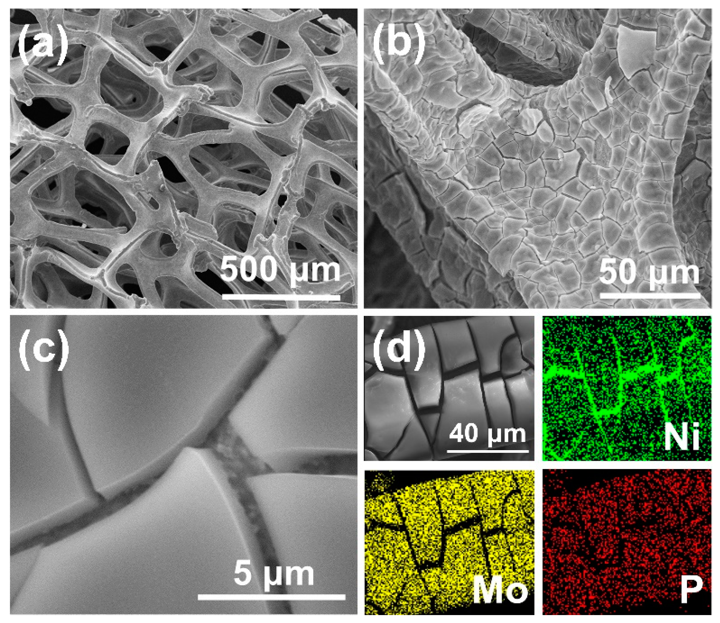
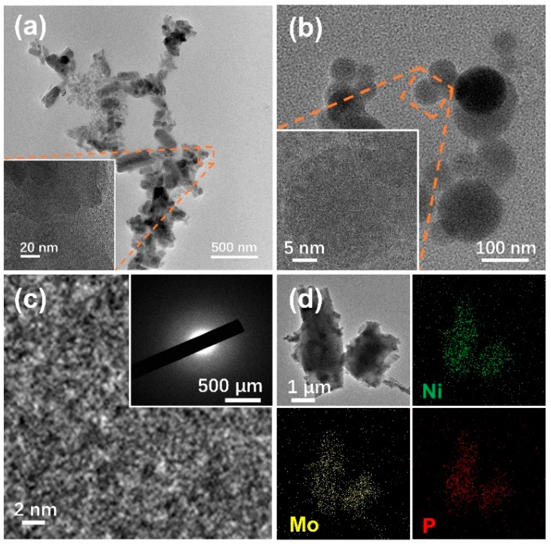
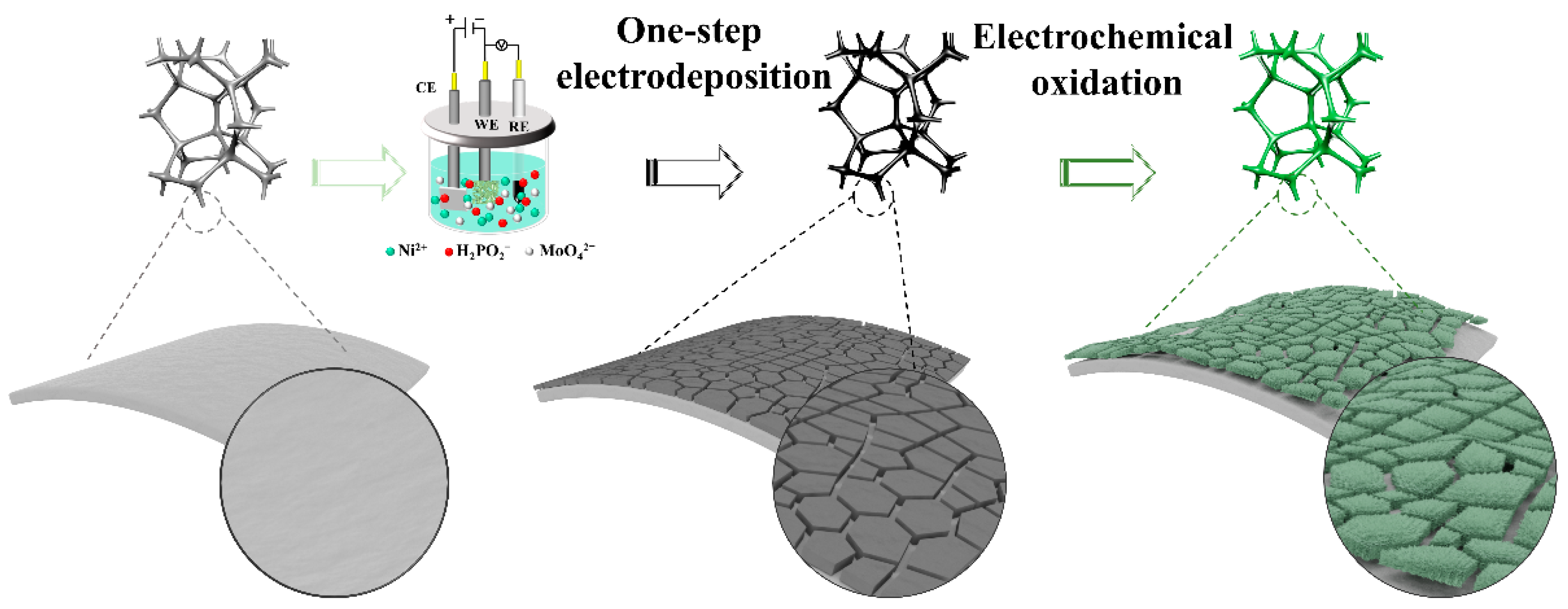
2.1. Preparation and Characterization of NiMoP/NF

As shown in Scheme 2, NiMoP film is directly grown on three-dimensional porous nickel foam (NF) by electrodeposition method at ambient pressure and temperature, without using any catalyst binder, which is often required during the powdered catalyst ink spraying process. An active NiOOH layer on the surface of this monolithic electrode is obtained by electrochemical oxidative activation in the subsequent step. At the same time, Ni(OH)2/NF and NiP/NF are also synthesized as control samples for comparison purposes (Figure S1).
The morphology and element distribution of NiMoP/NF was characterized by scanning electron microscopy (SEM). When the SEM images of NiMoP/NF (Figure 1a–c) are compared with that of bare NF (Figure S2), it can be seen that the surface of the NF skeleton is uniformly covered with a rimous film after electrodeposition. Additionally, the result of SEM–EDS (Figure 1d) shows that the Ni, Mo, and P elements are evenly distributed on the island pieces. In the cracks of the fructose film, however, there is only a remarkable amount of Ni (Figure 1d), indicating that the cracks are an exposed NF substrate. The SEM results of NiP/NF without Mo (Figure S3a) show that the electrodeposited film is composed of small and closely arranged particles. Therefore, the fragmented surface layer of NiMoP/NF is possibly caused by the high internal stress related to Mo [15]. To further verify this hypothesis, NiMoP/NF samples with different Ni/Mo ratios are prepared, and their SEM images show that the higher the Mo content in the coating is, the more and wider cracks there are (Figure S4).
X-ray diffraction (XRD) tests were carried out to study the phase structure of the samples. The XRD patterns of NF, Ni(OH)2/NF, NiP/NF, and NiMoP/NF exhibit three diffraction peaks at 44.8°, 52.1°, and 76.6° (Figure S5a), corresponding to the (111), (200), and (220) crystallographic planes of nickel [16]. The local magnification of the Ni(OH)2/NF XRD pattern reveals that characteristic peaks could be matched with JPCDS No. 14-01117 (Figure S5b). The Ni(OH)2 phase is further confirmed by the classical lamellar structure of hydroxide depicted in a SEM image (Figure S3b) [17]. Consistent with the XRD results of the film structure prepared by one-step electrodeposition in other studies, wide diffraction peaks centered at around 21.5° (Figure S5c) and 22.0° (Figure S5d) can be seen in XRD patterns of NiP/NF and NiMoP/NF, implying the amorphous properties of the two electrodeposited films [15,16,18]. The electrodeposited NiMoP film on an NF surface was then studied by high-resolution transmission electron microscopy (HRTEM). In magnified HRTEM images with a 2–20 nm scale bar (Figure 2a–c), no ordered lattice fringe can be found, while there is no lattice diffraction ring in the selected area electron diffraction (SAED) pattern (inset in Figure 2c). These findings are in line with the XRD results, implying the amorphous structure of NiMoP coating [19,20]. In addition, the results of energy dispersive X-ray spectroscopy attached to TEM (TEM–EDS) show that the Ni, Mo, and P elements are evenly distributed across the entire region of the sample (Figure 2d), echoing with the elemental distribution result based on the SEM–EDS analysis.
The surface elements and their chemical valence states of NiMoP/NF were analyzed by X-ray photoelectron spectroscopy (XPS). The XPS survey spectra showed the presence of the Ni, Mo, P, O, and C elements in the as-prepared NiMoP/NF (Figure S6). The element O may come from air oxidation, and the element C is originated from the reference carbon. The XPS peaks in the Ni 2p region (Figure 3a) were fitted into six peaks for NiMoP/NF before and after electrolysis. Regarding the as-synthesized NiMoP/NF, the two peaks located at about 852.4 and 869.8 eV are assigned to the spin–orbit doublet of 2p orbital of Ni0 [14,21,22,23]. As discussed in the SEM analysis part, the cracks on the rimous NiMoP film lead to partial exposure of the NF substrate (Figure 1d), which could be a major source of Ni0 signal. The Ni0 peaks disappeared after electrolysis, suggesting that the complete oxidative transformation of metallic nickel happened on the electrode surface. The binding energy peaks at 856.1 eV (Ni 2p 3/2) and 873.8 eV (Ni 2p 1/2) are attributed to the spin–orbit bimodal pattern of Ni2+ [24,25,26,27], accompanied by associated satellite peaks at 861.4 and 880.0 eV [28,29,30,31,32]. The Ni2+ peaks exist in the XPS pattern both before and after electrolysis, revealing that Ni2+ could directly participate in the reaction as active sites or indirectly participate in the reaction as an electron donor of the Ni(OH)2/NiOOH redox pair [33]. It is notable that new bimodal peaks at 857.6 and 875.1 eV appeared in the XPS results of NiMoP after HMFOR [24,34], which can be assigned to the spin–orbit doublet of 2p orbital of Ni3+ (NiOOH) [35]. NiOOH is considered to be the active site that could mediate HMFOR. The XPS spectrum of the Mo 3d region (Figure 3b) is deconvoluted into four peaks after fitting. Among them, peaks positioned at 234.6 and 231.5 eV belong to Mo5+ [36] with a binding energy distance of 3.1 eV. The peaks at 229.6 and 233.1 eV are associated with Mo4+ [37] originated from the reduction of MoO4−2 during the electrodeposition process. For P 2p spectra (Figure 3c), the peak at 133.1 eV is characteristic of phosphate species due to superficial oxidation of the NiMoP after exposure to air [38]. The intensity of peaks in the Mo 3d and P 2p region drastically drops after electrolysis, suggesting that the Mo and P elements are selectively removed by being oxidized into water-soluble anions. This corrosive loss of the Mo and P elements could create more exposed Ni(OH)2/NiOOH redox pair facilitating HMFOR.

2.2. Electrocatalytic HMF Oxidation Performance of NiMoP/NF

With water as the major solvent, the competitive reaction of HMFOR is electrode oxidation and OER on the anode side. Therefore, electrocatalytic properties of NiMoP/NF towards electrode oxidation, HMFOR, and OER were evaluated in an alkaline solution. The blank linear sweep voltammetry (LSV) polarization curve (Figure 4a) indicates that the NiMoP/NF electrode has an oxidation peak from 1.34 (vs. RHE) to 1.46 V (vs. RHE) (region I), which can be interpreted as the electrode surface oxidation of Ni2+ (Ni(OH)2) to Ni3+ (NiOOH) [33,39]. In the Ni2+/Ni3+ mediated alcohol oxidation mechanism, NiOOH is the active phase for alcohol oxidation reaction and will be reduced to Ni(OH)2 after organic molecules are oxidized [40]. When NiMoP/NF is placed into the HMF containing electrolyte under >1.34 V (vs. RHE) anode potential, the generated NiOOH participates in the HMFOR, generating Ni(OH)2 that will be reoxidized to NiOOH in the LSV scanning process. The electrode oxidation and HMFOR give rise to the large current density, as shown by the red curve in region I. When the applied potential is higher (region II), the current density reflects the direct oxidation of HMF on the NiOOH surface [33]. Then, the water oxidation reaction initiates when the anode potential is higher than 1.51 V (vs. RHE). In the cyclic voltammetry (CV) curve with NiMoP/NF as working electrode (WE) (Figure S7), a pair of redox peaks at about 1.40 V (vs. RHE) and 1.25 V (vs. RHE) are reversible redox transitions between Ni(OH)2 and NiOOH [33,39]. Quantitatively, to deliver a catalytic current density of 50 mA·cm−2, NiMoP/NF only requires an overpotential of 1.36 V towards HMFOR, while it needs 1.62 V towards OER. Hence, HMFOR is an energy-efficient alternative to OER for a paired electrolysis system.
To compare electrocatalytic activity of different electrodes towards HMFOR, the LSV tests (Figure S8) of NF and three nickel-based electrodes (synthesis methods shown in Figure S1) in 50 mM HMF in 1.0 M KOH were conducted. The results show that NiMoP/NF requires the lowest applied potential to reach the same current density (Figure 4b). At the same time, the corresponding Tafel slopes calculated from Figure S8 to evaluate HMF electro-oxidation kinetics are shown in Figure 4c. The Tafel slope of NiMoP/NF is 56.16 mV·dec−1, which is smaller than that of Ni(OH)2/NF (142.39 mV·dec−1) and NiP/NF (61.95 mV·dec−1), indicating a faster electron transfer rate. Therefore, NiMoP/NF has the highest electrocatalytic activity towards HMFOR.
The electrochemically active surface area (ECSA) is also a common index to compare catalysts. The Cdl values for Ni(OH)2/NF, NiP/NF, and NiMoP/NF were 1.50, 2.36, and 5.65 mF∙cm−2, respectively (Figure 4d). Under the same testing condition, it is reasonable to assume that Cs = 40 μF∙cm−2 for nickel materials [41,42]. The calculated ECSA of NiMoP/NF is 141.25 cm2, much larger than that of Ni(OH)2/NF (37.38 cm2) and NiP/NF (58.88 cm2). The superior HMFOR performance of NiMoP/NF could benefit from its large active surface area. By comparing the morphology of the above three materials with SEM images (Figure 1 and Figure S3), it can be concluded that the large ECSA of NiMoP/NF can be partially traced back to the cracks and pore on its surface. Besides, in comparison with NF, the smaller value of charge transfer resistance (Rct) (Figure S9) is in conformity with its smaller Tafel slope of NiMoP/NF, which further verifies its outstanding HMFOR charge transfer kinetics [43].
The HMFOR product analysis was carried out with chronoamperometry (CA) tests accompanied by HPLC to monitor the concentration of HMF, FDCA, and intermediates at different electrolysis times. The reaction pathways of anodic HMFOR catalyzed by NiMoP/NF were studied using constant potential electrolysis at a potential with negligible OER (1.46 V vs. RHE). As the reaction time goes, the current density decreases gradually (Figure 5a) due to HMF consumption. The control experiment confirmed that NF substrate had relatively low HMFOR activity. The HPLC results of HMF oxidation at different electrolysis times show that (Figure 5b and Figure S10) 5-hydroxymethyl-2-furancarboxylic acid (HMFCA), 2-formyl-5-furancarboxylic acid (FFCA), and HMF were detected from the electrolyte within 5 min of the reaction. At 30 min, one-fifth of HMF was electrocatalytically oxidized, producing 18.9% FDCA, 1.7% HMFCA, and 0.1% FFCA. When the reaction lasted for 60 min, there was 91.9% HMF oxidized, of which 88.3% was completely oxidized to FDCA, and 3.6% was an intermediate by-product. At 120 min, HMFCA was completely transformed, and the solution consisted of 0.1% FFCA and 0.2% HMF in addition to 99.7% FDCA (Figure 5c). HMF is known to undergo disproportionation under a strong alkaline environment [43], which could be alleviated by the quick conversion of HMF There are generally two reaction pathways for the electrocatalytic oxidation of HMF to FDCA (Figure 5d) [11]. Since there is only HMFCA but no is DFF detected, it might be inferred that HMFOR favors reaction path I (Figure 5d) with HMFCA as the key reaction intermediate under the current testing conditions.
Within the anode potential window of 1.41–1.61 V (vs. RHE), the catalytic activity of NiMoP/NF for HMFOR was investigated in 1.0 M KOH and 10 mM HMF electrolyte. The results reveal (Figure 5e) that when the electrode potential reached the oxidation peak of Ni2+/Ni3+ (~1.46 V vs. RHE), the conversion of HMF could reach more than 98%, and the yield of FDCA could reach about 80.0%. As the competitive reaction when the anode potential is larger than 1.51 V (vs. RHE), OER suppresses the FE towards FDCA generation, while the yield of FDCA is also affected. The current density response of MoP/NF to HMFOR is very low, which is almost consistent with the response of OER (Figure S11), proving that Mo cannot directly contribute to HMFOR. Thus, the major active sites of NiMoP/NF for HMFOR are Ni3+ (NiOOH). When the Ni/Mo ratio changes from 1:1 to 5:1 (Figure S12), electrocatalytic activity towards HMFOR of NiP/NF is much lower than those of NiMoP/NF, Ni2MoP/NF, Ni4MoP/NF, and Ni5MoP/NF, indicating that the Mo addition during the catalyst preparation process has a positive effect for HMFOR and OER [44].

2.3. Electrohydrodimerization (EHD) of AN

To study the priority sequence of the electroreduction of AN and the hydrogen evolution reaction (HER) on the Pb electrode, linear sweep voltammetry (LSV) was performed in the electrolyte with different initial concentrations of AN first (Figure 6a). Although the current increased significantly with an AN concentration on the Pb electrode, the increasing trend of current was not proportional to that of the AN concentration. Requiring about −1.34 V (vs. RHE) to achieve 10 mA·cm−2, the blank LSV curve displayed a relatively low current response in the absence of AN due to the low HER activity of the Pb cathode and the obstruction of H+ transfer by a hydrophobic quaternary layer. However, even if only 0.19 M AN was added, the potential remarkably dropped to −1.09 V (vs. RHE), implying that the EHD of AN occurred preferentially on a lead electrode. To ensure that the anode and cathode reactions of the paired electrolysis system had a matched current density, the AN concentration was optimized in the range of 0.57–1.70 M as a bottleneck parameter for the EHD of AN. In the chronopotentiometry test, it was found that the higher the initial AN concentration was, the lower the conversion would be after 2 h (Figure 6a inset graph). Although the AN conversion decreased, the catalytic efficiency of the whole system was improved because more AN molecules can be reduced per unit time. Figure 6b shows the effect of an initial AN concentration at a current density of −75 mA·cm−2, embodying the significance of using a relatively high AN concentration. While the AN initial concentration increased from 0.57 to 1.70 M, the ADN selectivity gradually increased from 15.9% to 90.1%, confirming that the initial AN concentration plays a key role in affecting the ADN yield. Since the formation of 1 mol ADN requires 2 mol AN, a relatively high AN adsorption amount on the electrode surface is helpful for its dimerization to form ADN [45]. The areal production rate and energy productivity of ADN at −75 mA cm−2 (Figure 6c) reached peak values of 0.58 kgADN·h−1·cm−2 and 0.25 kgADN·kWh−1 at a 1.51 M AN concentration, offering a potential testing condition for paired electrolysis from the cathode viewpoint.
The solubility of AN in water is limited, providing insufficient contact between the electrode and AN to react efficiently. When the AN concentration in the water solution is higher than 1.32 M, the oil–water stratification will occur (Figure 6d). At this time, even vigorous stirring cannot make water and AN miscible. Suspended AN droplets in the solution are not conducive to the electrocatalytic reaction. In this work, AN is uniformly mixed with water by adding an N, N-dimethylformamide (DMF) cosolvent (Figure 6d). DMF is proved to be stable under electrolysis conditions since no additional product peak is detected (Figure 6e). Moreover, the results of LSV (Figure 6f) showed that 2.08 M DMF for the 1.51 M initial AN concentration is appropriate, while a superfluous (2.60 M) or insufficient (1.56 M) concentration of DMF would undermine the efficiency of the reaction.
In the range of −1.30 to −2.30 V (vs. RHE), the EHD of AN is studied by potential controlled electrolysis. It can be seen from Figure 6g that the product distribution is very sensitive to the cathodic potential variation. The more negative operating voltage is helpful to the ADN formation, leading to 90.8% ADN selectivity after 2 h chronoamperometry with −2.3 V (vs. RHE) applied potential. In the chronopotentiometry experiment with a 1.51 M initial AN concentration, the areal production rate obtained generally increased with the absolute value of the current density, reaching a maximum value of 1.10 kgADN h−1 m−2 at −84 mA·cm−2 (Figure 6h). Calculated by measuring the generated ADN mass per unit energy input, the energy productivity had a maximum value of 0.40 kgADN·kWh−1 at a current density of −43 mA·cm−2. As a high energy productivity fen energy consumption of the entire cell, −43 mA·cm−2 was an efficient ADN producing a current density under the current experiment conditions without severely suffering from OER as the side reaction. To study the temperature effect on the EHD of AN, constant current electrolysis was carried out under four temperatures (Figure S13). Since the low boiling point (77.35 °C) of AN resulted in its volatile loss at high temperatures, the selectivity of ADN was relatively large (85.4–87.5%) at relatively low temperatures (25–30 °C). At relatively low temperatures, molecular thermal motion was not intense, leading to a more integrated electric double layer that can attract ions onto the electrode surface with relatively low electrostatic driving force. It means that the concentration of AN and its free radical anion on the electrode surface is higher at low temperatures, so the formation rate of adiponitrile increases.

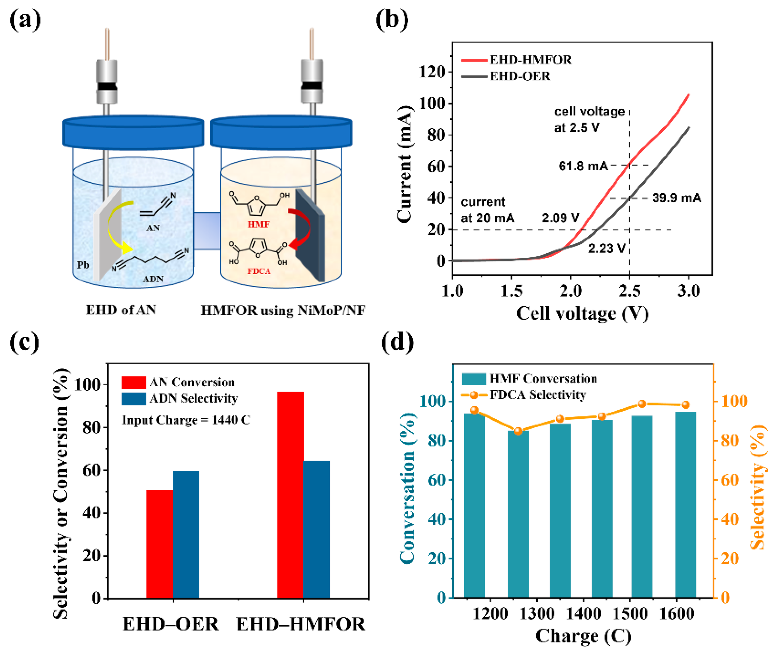
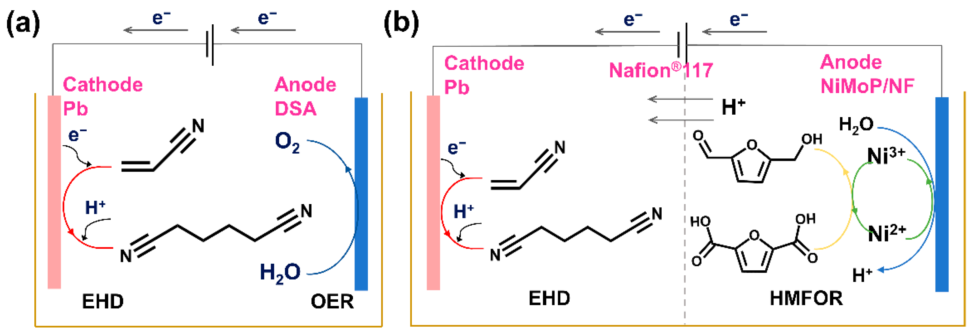
2.4. Paired Electrolysis of AN and HMF

Conventionally, the EHD of AN is coupled with OER, whose sluggish kinetics restrict the overall efficiency of the electrolytic process. In this paper, we attempted to bring down the required energy input by replacing anodic OER with the ECO of HMF, simultaneously generating ADN and FDCA as value-added products. As shown below (Figure 7a), the electrocatalytic HMFOR catalyzed by NiMoP/NF and the EHD of AN on a Pb electrode were paired (noted as an ANEHD–HMFOR paired system) in an H-type electrochemical cell (Figure S14). Except for the influence of H+ migration, the two reaction chambers do not interfere with each other due to the existence of a Nafion membrane between them. To demonstrate the feasibility and superiority of the new paired electrolysis system, we conducted LSV analysis in a two-electrode system. The results for an ANEHD–HMFOR paired electrolysis system exhibited a remarkable energy-saving effect compared with the ANEHD–OER system (e.g., 2.09 vs. 2.23 V at 20 mA; 61.8 vs. 39.9 mA at 2.5 V) (Figure 7b).
The current density can be used to control the two half reactions in a paired system [46]. In CP test, the ADN selectivity and conversion in the ANEHD–HMFOR system are better than those of the ANEHD–OER system with the same amount of charge passed (Figure S15). For instance, when 1440 C of electrons passes through the system (Figure 7c), the selectivity of ADN in ANEHD–HMFOR paired electrolysis is 64.4%, and the AN conversion can reach 96.7%. However, in the conventional ANEHD–OER electrolysis system, ADN selectivity and AN conversion are 60.0% and 50.7%, respectively. The conversion and selectivity of HMFOR in a paired electrolysis system are both higher than 80% (Figure 7d). Thus, a paired electrolysis of AN and HMF for the simultaneous generation of ADN and FDCA is achieved.
To check whether there are other elements deposited on the anode or cathode after electrolysis, SEM mapping tests were performed on the Pb cathode (Figure S16) and the NiMoP/NF anode (Figure S17) before and after electrolysis. For the Pb cathode, the Pb elements were uniformly distributed on the electrode surface before and after the paired electrolysis process, while there were no Ni, Mo, and P on the Pb electrode surface after the reaction, indicating that the relatively stable Ni elements or the Mo and P elements that were partially removed from the anode during the electrolysis process were not deposited on the Pb cathode. Meanwhile, there was no Pb element found on the NiMoP/NF anode surface after the electrolysis process. After the electrolysis process, the absence of new elements found on both cathode and anode surfaces can be partially attributed to the use of the Nafion 117 proton exchange membrane (DuPont Inc., Wilmington, DE, USA) which effectively blocks the conduction of ions other than hydrogen protons.
In addition, an energy consumption evaluation of the whole electrolyzer is shown in Figure S18, signifying that the ANEHD–HMFOR paired electrolysis system is a promising alternative to the ANEHD–OER system. Although the ANEHD–HMFOR system still needs more optimization, its current prototype provides a promising pathway for the future development of electroreforming technology.

3. Materials and Methods

3.1. Chemicals and Materials

All chemicals were gained from regular chemical reagent manufacturers. Sodium tetraborate decahydrate (99.5%), tetraethylammonium hydroxide (25.0%), disodium EDTA dihydrate (99.0%), adiponitrile (99.0%), 5-hydroxymethylfurfural (99.0%), and 2,5-furandicarboxylic acid (98.0%) were gained from Aladdin; acrylonitrile (≥99.0%) was obtained from Aldrich; potassium dihydrogen phosphate (≥99.5%), NiSO4·6H2O (≥98.5%), Ni(NO3)2·6H2O (≥98.0%), Na2MoO4·2H2O (≥99.0%), (NH4)2SO4 (≥99.0%), NaH2PO2·H2O (>98.0%), hydrochloric acid (36–38%), and urea (≥99.0%) were provided by Sinopharm Chemical Reagent Co.; N, N-dimethylformamide (≥99.5%), dichloromethane (≥99.5%), C6H5Na3O7·2H2O (≥99.0%), KOH (≥85.0%), and ethanol (≥99.5%) were purchased directly from Kermel Co., Tianjin, China.

3.2. Catalyst Synthesis Method

3.2.1. Synthesis of NiMoP/NF and NiP/NF

For pretreatment purposes, the NF substrate was washed in ultrasonic water bath with acetone, 1.0 M hydrochloric acid, and ethanol one after another (each for 10 min) to remove surface oxides and pollutants. The NF was further rinsed with water and ethanol repeatedly, and finally dried in a N2-protected environment. The NiMoP/NF electrode was prepared by galvanostatic electrodeposition method at room temperature. The NF was put into a three-electrode system with a platinum sheet as the counter electrode, and saturated calomel electrode (SCE) as the reference electrode. Employed as the working cathode, the NF (1 cm × 1 cm) was galvanostatically electrodeposited at −60 mA·cm−2 for 1 h in a 25 mL electrodeposition solution composed of 0.250 g NiSO4·6H2O, 0.375 g C6H5Na3O7·2H2O, 0.375 g (NH4)2SO4, 0.400 g NaH2PO2·H2O, 0.200 g Na2MoO4·2H2O, and deionized (DI) water. The Mo and P contents in the electrodeposition solution were kept the same as above, while the Ni content was adjusted for NiMoP/NF synthesis with different Ni amount. The procedures for the synthesis of NiP/NF and MoP/NF were similar to that of the synthesis of NiMoP/NF mentioned above.

3.2.2. Synthesis of Ni(OH)2/NF Hydrothermal Method

The pretreatment of NF was the same as above. Ni(NO3)2·6H2O (0.400 g) and urea (0.360 g) were added into DI water (30 mL) and fully dissolved by magnetic stirring for 30 min. The treated NF and the solution were put together into the PTFE inner lining of the autoclave reactor. The autoclave was placed in a constant temperature drying oven at 120 °C for 20 h and then taken out. After cooling down to room temperature, Ni(OH)2/NF was taken out from the inner lining and washed with DI water repeatedly before storage.

3.3. Physical Characterization

The XRD patterns were obtained by a Rigaku SmartLab 9 KW diffractometer (Rigaku Co., Tokyo, Japan) equipped with a Cu Kα1 radiation source (λ = 1.5406 Å) operated at 240 kV and 50 mA. The XRD tests were performed within the 2θ angle range between 5° and 90° at a scanning rate of 20° min−1 with a step length of 0.02°. The morphology and structure of catalytic materials were examined by a QUANTA 450 scanning electron microscope (FEI Ltd., Waltham, MA, USA) operated at 30 kV with a resolution limit of 3 nm. An energy dispersive spectrometer (EDS) helped to analyze the element composition. The scanning transmission electron microscopy (STEM) images of the internal structure were taken by a JEM-F200 transmission electron microscope (JEOL Ltd., Tokyo, Japan) operated at 200 kV accelerating voltage. The preparation method of the STEM sample was as follows: NiMoP/NF was put into a centrifuge tube filled with ethanol, followed by ultrasonic treatment for 30 min to physically remove some loosely attached film from the sample surface. Then 1–2 drops of the solution containing a detached film structure were added onto the double-membrane copper mesh. After drying for 5 min, the copper mesh was transferred onto the sample holder with tweezers. X-ray photoelectron spectroscopy (XPS) spectra were acquired on an ESCALAB Xi+ XPS (Thermo Fisher Scientific Inc., Waltham, MA, USA). Samples were prepared and rinsed well and purged with N2 to dryness. The binding energy was corrected by C 1s peak at 284.8 eV.

3.4. Evaluation of Electrochemical Reactions

All electrochemical reactions were performed with an Autolab PGSTAT302N electrochemistry workstation (Metrohm AG Inc., Herisau, Switzerland).

3.4.1. Anode Reaction—Electrocatalytic HMF Oxidation Reaction

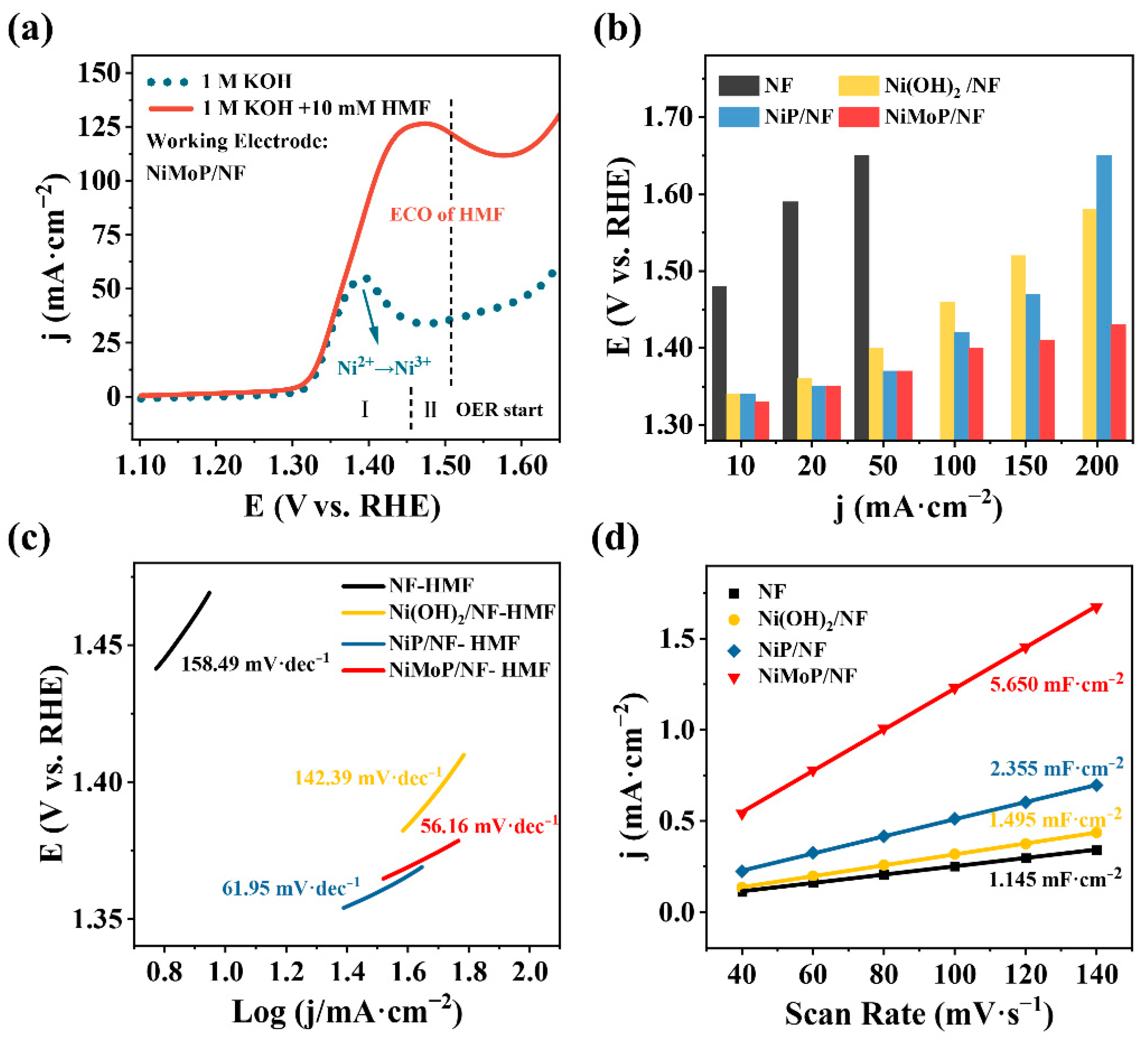
  • The electrochemical characterization of anode materials. The CV and LSV tests were performed in a three-electrode cell with a 25 mL electrolyte at room temperature. The as-prepared catalytic materials (1 cm × 1 cm), Pt sheet (1 cm × 1 cm), and Hg/HgO electrode (filled with 1.0 M KOH) acted as WE, CE and RE, respectively. The LSV experiments regarding electrocatalytic HMFOR and OER were conducted in a KOH electrolyte with and without HMF at a scan rate of 10 mV·s−1 within a 1.09–1.65 V (vs. RHE) anode potential window. To evaluate the ECSA of these monolithic catalysts, CV tests were conducted in the non-Faradaic region from 0.97 to 1.07 (vs. RHE) at 40, 60, 80, 100, 120, and 140 mV·s−1. CV tests were also employed to study HMFOR and OER by choosing a 1.05–1.60 V scan range at a 10 mV·s−1 scan rate for 10 cycles.
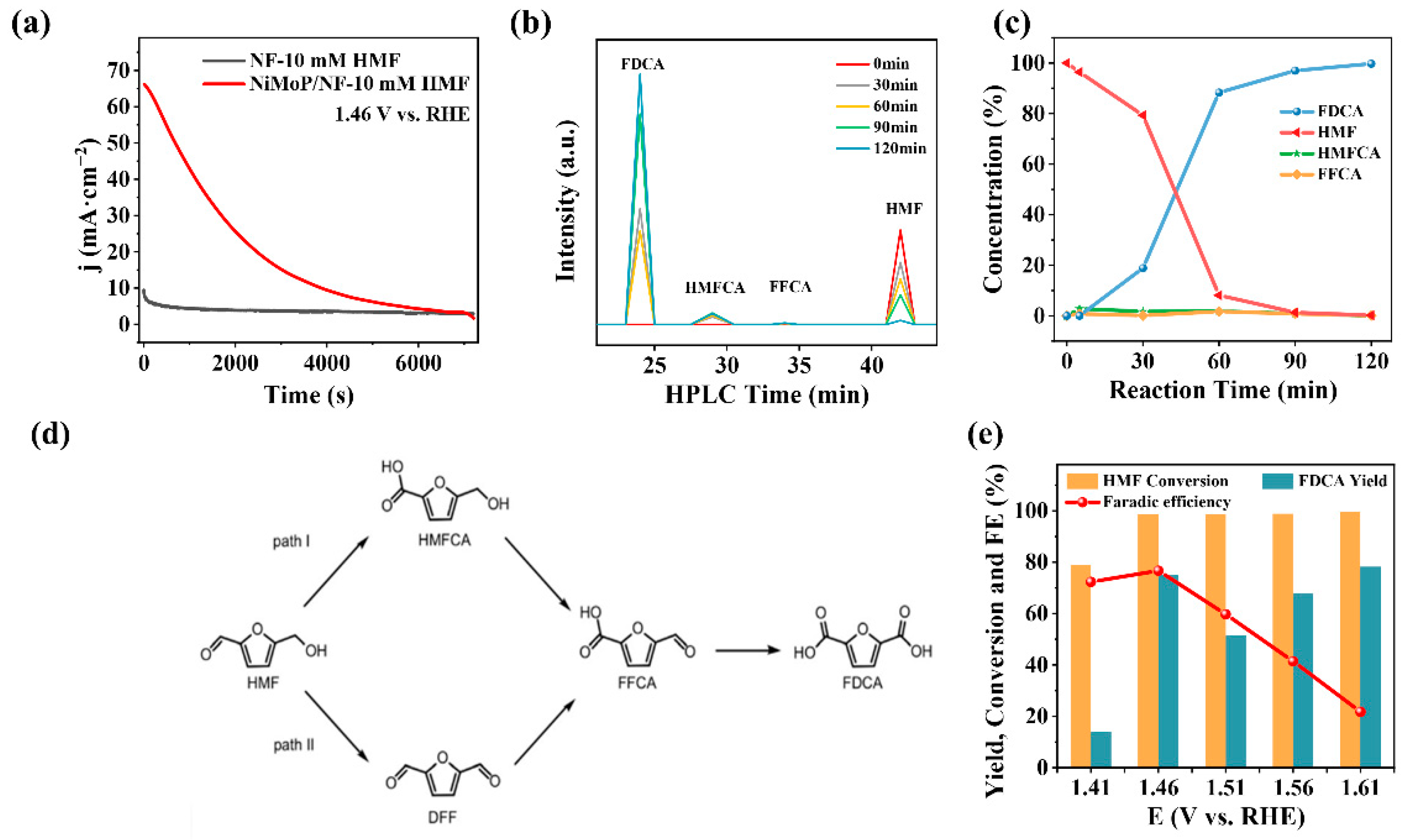
  • The product distribution analysis of electrocatalytic HMFOR catalyzed by NiMoP/NF anode. In the three-electrode system, the product distribution analysis was carried out with CA tests in a 25 mL 1 M KOH electrolyte containing 10 mM HMF at around 30 °C. During the electrolysis, the electrolyte was magnetically stirred (1000 rpm) and deaerated with N2 to remove oxygen and hydrogen.

3.4.2. Cathode Reaction—Electrohydrodimerization of AN

Under vigorously stirring (1000 rpm), the ANEHD was performed in a diaphragmless electrolytic cell with (IrO2)x(Ta2O5)y/Ti (DSA, dimensionally stable anode), Pb sheet (2 cm × 2 cm), and SCE (filled with KCl saturated solution) as WE, CE, and RE, respectively. The 25 mL electrolyte was composed of 1.0 g sodium tetraborate decahydrate, 0.2 g disodium EDTA dihydrate, 1.5 g potassium dihydrogen phosphate, and DI water along with different concentrations of the acrylonitrile, tetraethylammonium hydroxide, and DMF.

3.4.3. The ANEHD–HMFOR Paired Electrolysis System in H-Cell

The electrodes and 25 mL electrolytes for paired electrolysis were similar to those described in Section 3.4.1 and Section 3.4.2: Separated with a Nafion 117 membrane, the anode and cathode chambers of the H-cell have NiMoP/NF and Pb sheet inside, respectively. The system kept the 30 °C temperature, N2 atmosphere, and 1000 rpm stirring continuously during the electrolysis process.

3.5. Quantification Methods

3.5.1. Cathode Samples Analyzed by Gas Chromatography (GC)

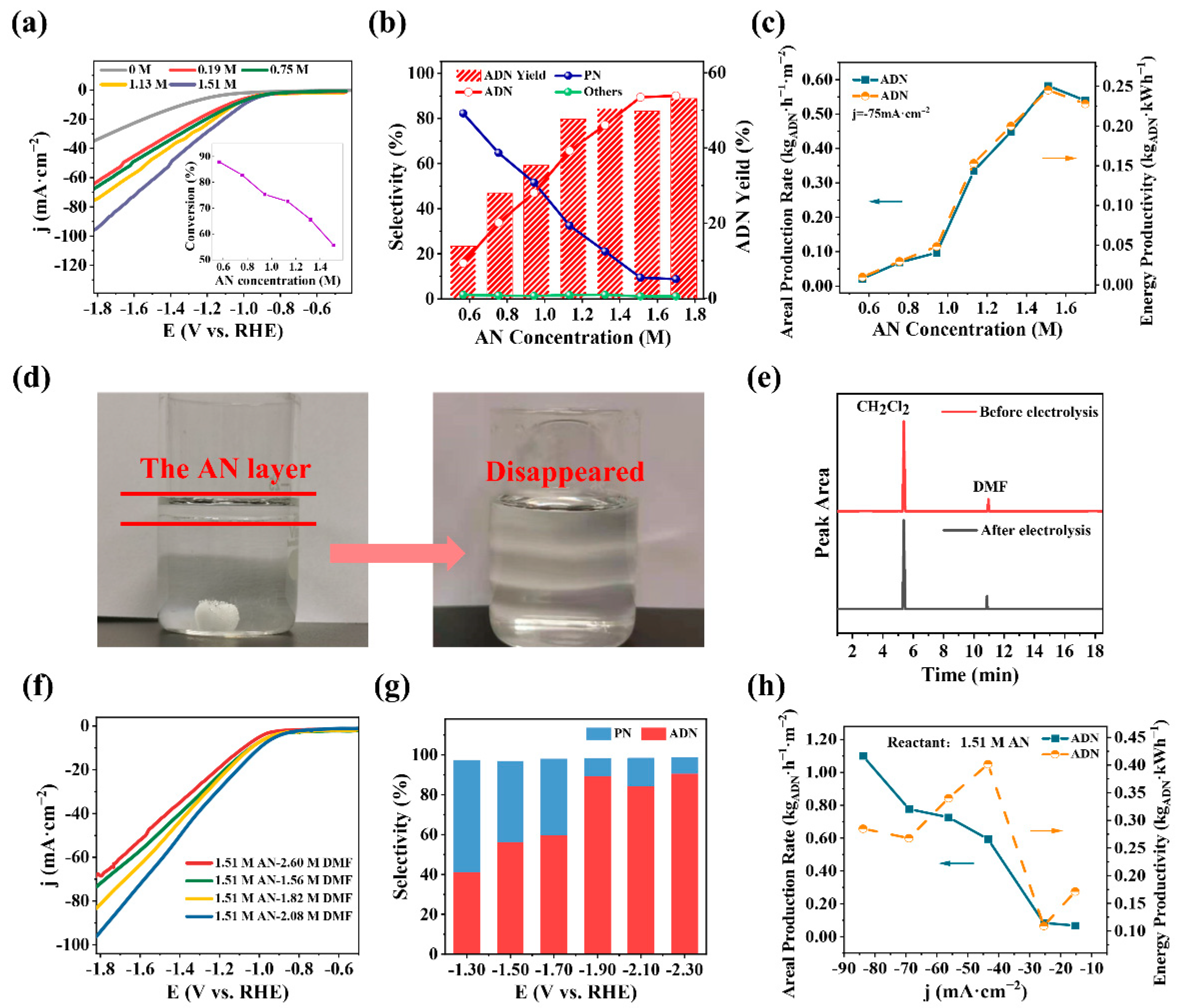
  • The organic substances in the cathode solution (500 μL) were separated by liquid–liquid extraction using dichloromethane (1000 μL) as the extracting solvent. The upper oil phase was taken out, and 1 mL lower liquid was taken into the chromatographic bottle.
  • Then the extracted samples were analyzed with Agilent 7890 GC equipped with a DB-FFAP (30 m × 0.320 mm × 0.50 μm) column and a flame ionization detector (FID). The detailed GC analyzing parameters are as follows: injection-port temperature = 280 °C, split ratio = 10:1, column temperature = 50 (5 min hold time before heating)–250 °C (20 °C/min heating rate), column N2 carrier gas flow rate = 0.896 mL/min, FID temperature = 300 °C, air flow rate = 400 mL/min, H2 flow rate = 30 mL/min.

3.5.2. Anode Samples Analyzed by HPLC

  • Preparation of an anode sample: a 100 μL reaction solution and 900 μL mobile phase were mixed, filtered, and placed in an autosampler vial.
  • The anode samples were analyzed by Waters HPLC equipped with a 2998 photodiode array detector. The mobile phase was 0.01 M H2SO4 with a 0.6 mL/min flow rate. The wavelength of the detector was set to 265 nm to quantify anode products.
Standard curves are shown in Figure S19.

4. Conclusions

In summary, this work demonstrated paired electrolysis of AN and HMF for the simultaneous generation of ADN and FDCA. On the anode side, the electrodeposited NiMoP amorphous film-covered nickel foam efficiently boosted HMFOR activity by enlarging the ECSA by in situ selective removal of Mo and P on the surface. On the cathode side, the addition of DMF as a cosolvent successfully enhanced the reaction efficiency of ANEHD by forming a single-phase electrolyte that offers better interaction between AN and the electrode.
Since the conversion rates of substrate molecules are both increased at the anode and cathode sides, the ANEHD–HMFOR paired electrolysis system can achieve high generation rates of FDCA (0.018 gFDCA·h−1·cm−2) and ADN (0.017 gADN·h−1·cm−2) at a high cell current (i = 160 mA). Compared with the conventional ANEHD–OER electrolysis system, the ANEHD–HMFOR paired system not only saves energy by replacing OER with HMFOR, but also offers great economic value by cogeneration of FDCA. An amount of 1 kWh of electricity can produce 2.91 mol of ADN and 0.53 mol of FDCA with 107.1% Faraday efficiency. This process also avoids the direct contact of oxygen with organic molecules, preventing the potential explosion risk.

Supplementary Materials

The following supporting information can be downloaded at: https://0-www-mdpi-com.brum.beds.ac.uk/article/10.3390/catal12070694/s1: Figure S1. Schematic illustration of the synthesis process for (a) Ni(OH)2/NF, (b) NiP/NF, and (c) NiMoP/NF; Figure S2. Scanning electron microscopy (SEM) figures of cleaned nickel foam (NF) surface; Figure S3. SEM images of (a) NiP/NF, (b) Ni(OH)2/NF; Figure S4. SEM images of NiMoP/NF catalysts with different Ni/Mo ratios: (a) Ni1Mo1P/NF, (b) Ni2Mo1P/NF, (c) Ni4Mo1P/NF, (d) Ni5Mo1P/NF, (e) NiP/NF, (f) NiMo/NF; Figure S5. (a) XRD patterns of NF, Ni(OH)2/NF, NiP/NF, and NiMoP/NF; XRD fine patterns of (b) Ni(OH)2/NF, (c) NiP/NF, and (d) NiMoP/NF local areas, respectively; Figure S6. XPS spectra survey of NiMoP/NF; Figure S7. Cyclic voltammogram (CV) curves of NiMoP/NF and NF electrodes measured at a scan rate of 10 mV·s−1 in 1.0 M KOH with and without 10 mM HMF; Figure S8. LSV curves at a 10 mV·s−1 scan rate with NF, Ni(OH)2/NF, NiP/NF, and NiMoP/NF as working electrodes in 1.0 M KOH and 50 mM HMF electrolyte; Figure S9. Nyquist plots obtained with Ni(OH)2/NF as a working electrode in 1.0 M KOH and 50 mM HMF solution; Figure S10. High-performance liquid chromatography (HPLC) results (peak height trends) at various electrolysis times; Figure S11. LSV of NiMoP/NF and NF for HMFOR and OER; Figure S12. LSV curves of NiMoP/NF with different Ni/Mo ratios for (a) OER and (b) HMFOR (10 mM HMF) in 1.0 M KOH; Figure S13. Selectivity and yield for electrohydrodimerization of AN under different temperatures, conditions: 1.32 M initial AN concentration, 1.56 M DMF, 0.20 M TAA, −62.5 mA·cm−2; Figure S14. Experimental device of a paired system: HMFOR (left) and EHD of AN (right); Figure S15. Selectivity, yield, and conversion for ECO of HMF in two systems; Figure S16. SEM image and corresponding element mapping for a Pb cathode (a–b) before and (c–d) after paired electrolysis; Figure S17. SEM image and corresponding element mapping for Ni-MoP/NF anode (a–d) before and (e–i) after paired electrolysis; Figure S18. Energy consumption and trend in the ANEHD–OER and ANEHD–HMFOR systems; Figure S19. GC standard curves of (a) AN, (b) ADN; HPLC standard curves of (c) HMF, (d) FDCA. References [41,42,47] are cited in the Supplementary Materials.

Author Contributions

Conceptualization, methodology, software, writing—review and editing, J.Q.; formal analysis, investigation, writing—original draft preparation, Z.A.; resources, supervision, X.C.; project administration, supervision, C.L. (Chuang Li); formal analysis, software, Y.D.; validation, X.Z.; funding acquisition, supervision, project administration, C.L. (Changhai Liang). All authors have read and agreed to the published version of the manuscript.

Funding

This work was financially supported by the National Natural Science Foundation of China (21373038, 21703028), Fundamental Research Funds for the Central Universities (DUT20LK26, DUT21TD103), and China Postdoctoral Science Foundation (2018M630290).

Data Availability Statement

Not applicable.

Acknowledgments

We thank Jiaqi Liu for her technical support.

Conflicts of Interest

The authors declare that they have no known competing financial interest or personal relationship that could have appeared to influence the work reported in this paper.

References

  1. Wu, S.; Zhang, H.; Huang, X.; Liao, Q.; Wei, Z. Acrylonitrile Conversion on Metal Cathodes: How Surface Adsorption Determines the Reduction Pathways. Ind. Eng. Chem. Res. 2021, 60, 8324–8330. [Google Scholar] [CrossRef]
  2. Luo, H.; Barrio, J.; Sunny, N.; Li, A.; Steier, L.; Shah, N.I.; Stephens, I.E.L.; Titirici, M.M. Progress and Perspectives in Photo- and Electrochemical-Oxidation of Biomass for Sustainable Chemicals and Hydrogen Production. Adv. Energy Mater. 2021, 11, 2101180. [Google Scholar] [CrossRef]
  3. Qi, Y.F.; Wang, K.Y.; Sun, Y.; Wang, J.; Wang, C. Engineering the Electronic Structure of NiFe Layered Double Hydroxide Nanosheet Array by Implanting Cationic Vacancies for Efficient Electrochemical Conversion of 5-Hydroxymethylfurfural to 2,5-Furandicarboxylic Acid. Acs Sustain. Chem. Eng. 2022, 10, 645–654. [Google Scholar] [CrossRef]
  4. Kunnikuruvan, S.; Nair, N.N. Mechanistic Insights into the Bronsted Acid-Catalyzed Dehydration of beta-D-Glucose to 5-Hydroxymethylfurfural under Ambient and Subcritical Conditions. ACS Catal. 2019, 9, 7250–7263. [Google Scholar] [CrossRef]
  5. Liu, W.J.; Dang, L.N.; Xu, Z.R.; Yu, H.Q.; Jin, S.; Huber, G.W. Electrochemical Oxidation of 5-Hydroxymethylfurfural with NiFe Layered Double Hydroxide (LDH) Nanosheet Catalysts. ACS Catal. 2018, 8, 5533–5541. [Google Scholar] [CrossRef]
  6. Yang, Y.C.; Mu, T.C. Electrochemical oxidation of biomass derived 5-hydroxymethylfurfural (HMF): Pathway, mechanism, catalysts and coupling reactions. Green Chem. 2021, 23, 4228–4254. [Google Scholar] [CrossRef]
  7. Chadderdon, D.J.; Xin, L.; Qi, J.; Qiu, Y.; Krishna, P.; More, K.L.; Li, W.Z. Electrocatalytic oxidation of 5-hydroxymethylfurfural to 2,5-furandicarboxylic acid on supported Au and Pd bimetallic nanoparticles. Green Chem. 2014, 16, 3778–3786. [Google Scholar] [CrossRef]
  8. You, B.; Jiang, N.; Liu, X.; Sun, Y. Simultaneous H2 Generation and Biomass Upgrading in Water by an Efficient Noble-Metal-Free Bifunctional Electrocatalyst. Angew. Chem. Int. Ed. 2016, 55, 9913–9917. [Google Scholar] [CrossRef]
  9. Jiang, N.; You, B.; Boonstra, R.; Terrero Rodriguez, I.M.; Sun, Y. Integrating electrocatalytic 5-hydroxymethylfurfural oxidation and hydrogen production via Co–P-derived electrocatalysts. ACS Energy Lett. 2016, 1, 386–390. [Google Scholar] [CrossRef]
  10. Zhang, N.N.; Zou, Y.Q.; Tao, L.; Chen, W.; Zhou, L.; Liu, Z.J.; Zhou, B.; Huang, G.; Lin, H.Z.; Wang, S.Y. Electrochemical Oxidation of 5-Hydroxymethylfurfural on Nickel Nitride/Carbon Nanosheets: Reaction Pathway Determined by In Situ Sum Frequency Generation Vibrational Spectroscopy. Angew. Chem. Int. Ed. 2019, 58, 15895–15903. [Google Scholar] [CrossRef]
  11. Barwe, S.; Weidner, J.; Cychy, S.; Morales, D.M.; Dieckhofer, S.; Hiltrop, D.; Masa, J.; Muhler, M.; Schuhmann, W. Electrocatalytic Oxidation of 5-(Hydroxymethyl)furfural Using High-Surface-Area Nickel Boride. Angew. Chem. Int. Ed. 2018, 57, 11460–11464. [Google Scholar] [CrossRef] [PubMed]
  12. Heidary, N.; Kornienko, N. Electrochemical biomass valorization on gold-metal oxide nanoscale heterojunctions enables investigation of both catalyst and reaction dynamics with operando surface-enhanced Raman spectroscopy. Chem. Sci. 2020, 11, 1798–1806. [Google Scholar] [CrossRef] [PubMed] [Green Version]
  13. Chen, C.; Zhou, Z.; Liu, J.; Zhu, B.; Hu, H.; Yang, Y.; Chen, G.; Gao, M.; Zhang, J. Sustainable biomass upgrading coupled with H2 generation over in-situ oxidized Co3O4 electrocatalysts. Appl. Catal. B 2022, 307, 121209. [Google Scholar] [CrossRef]
  14. Liu, H.; Lee, T.-H.; Chen, Y.; Cochran, E.W.; Li, W. Paired electrolysis of 5-(hydroxymethyl)furfural in flow cells with a high-performance oxide-derived silver cathode. Green Chem. 2021, 23, 5056–5063. [Google Scholar] [CrossRef]
  15. Abdel Hamid, Z.; Hassan, H.B. Influence of electrodeposition parameters on the characteristics of NiMoP film. Surf. Coat. Technol. 2012, 212, 37–45. [Google Scholar] [CrossRef]
  16. Toghraei, A.; Shahrabi, T.; Barati Darband, G. Electrodeposition of self-supported Ni-Mo-P film on Ni foam as an affordable and high-performance electrocatalyst toward hydrogen evolution reaction. Electrochim. Acta 2020, 335, 135643. [Google Scholar] [CrossRef]
  17. Xiang, Q.; Li, F.; Chen, W.; Ma, Y.; Wu, Y.; Gu, X.; Qin, Y.; Tao, P.; Song, C.; Shang, W. In situ vertical growth of Fe–Ni layered double-hydroxide arrays on Fe–Ni alloy foil: Interfacial layer enhanced electrocatalyst with small overpotential for oxygen evolution reaction. ACS Energy Lett. 2018, 3, 2357–2365. [Google Scholar] [CrossRef]
  18. Du, Y.; Pan, G.; Wang, L.; Song, Y. CoxNiyP embedded in nitrogen-doped porous carbon on Ni foam for efficient hydrogen evolution. Appl. Surf. Sci. 2019, 469, 61–67. [Google Scholar] [CrossRef]
  19. Wu, G.; Zheng, X.; Cui, P.; Jiang, H.; Wang, X.; Qu, Y.; Chen, W.; Lin, Y.; Li, H.; Han, X. A general synthesis approach for amorphous noble metal nanosheets. Nature Commun. 2019, 10, 4855. [Google Scholar] [CrossRef] [Green Version]
  20. Duan, Y.X.; Meng, F.L.; Liu, K.H.; Yi, S.S.; Li, S.J.; Yan, J.M.; Jiang, Q. Amorphizing of Cu nanoparticles toward highly efficient and robust electrocatalyst for CO2 reduction to liquid fuels with high faradaic efficiencies. Adv. Mater. 2018, 30, 1706194. [Google Scholar] [CrossRef]
  21. Che, Q.; Li, Q.; Chen, X.; Tan, Y.; Xu, X. Assembling amorphous (Fe-Ni)Cox-OH/Ni3S2 nanohybrids with S-vacancy and interfacial effects as an ultra-highly efficient electrocatalyst: Inner investigation of mechanism for alkaline water-to-hydrogen/oxygen conversion. Appl. Catal. B 2020, 263, 118338. [Google Scholar] [CrossRef]
  22. Fu, S.; Song, J.; Zhu, C.; Xu, G.-L.; Amine, K.; Sun, C.; Li, X.; Engelhard, M.H.; Du, D.; Lin, Y. Ultrafine and highly disordered Ni2Fe1 nanofoams enabled highly efficient oxygen evolution reaction in alkaline electrolyte. Nano Energy 2018, 44, 319–326. [Google Scholar] [CrossRef]
  23. Wang, M.; Wang, Y.; Mao, S.S.; Shen, S. Transition-metal alloy electrocatalysts with active sites modulated by metal-carbide heterophases for efficient oxygen evolution. Nano Energy 2021, 88, 106216. [Google Scholar] [CrossRef]
  24. Su, H.; Song, S.; Gao, Y.; Li, N.; Fu, Y.; Ge, L.; Song, W.; Liu, J.; Ma, T. In Situ Electronic Redistribution Tuning of NiCo2S4 Nanosheets for Enhanced Electrocatalysis. Adv. Funct. Mater. 2022, 32, 2109731. [Google Scholar] [CrossRef]
  25. Ito, Y.; Ohto, T.; Hojo, D.; Wakisaka, M.; Nagata, Y.; Chen, L.; Hu, K.; Izumi, M.; Fujita, J.-i.; Adschiri, T. Cooperation between holey graphene and NiMo alloy for hydrogen evolution in an acidic electrolyte. ACS Catal. 2018, 8, 3579–3586. [Google Scholar] [CrossRef]
  26. Liu, H.; He, Q.; Jiang, H.; Lin, Y.; Zhang, Y.; Habib, M.; Chen, S.; Song, L. Electronic Structure Reconfiguration toward Pyrite NiS2 via Engineered Heteroatom Defect Boosting Overall Water Splitting. ACS Nano 2017, 11, 11574–11583. [Google Scholar] [CrossRef]
  27. Luo, W.; Wang, Y.; Luo, L.; Gong, S.; Wei, M.; Li, Y.; Gan, X.; Zhao, Y.; Zhu, Z.; Li, Z. Single-Atom and Bimetallic Nanoalloy Supported on Nanotubes as a Bifunctional Electrocatalyst for Ultrahigh-Current-Density Overall Water Splitting. ACS Catal. 2022, 12, 1167–1179. [Google Scholar] [CrossRef]
  28. Wang, Z.; Xu, L.; Huang, F.; Qu, L.; Li, J.; Owusu, K.A.; Liu, Z.; Lin, Z.; Xiang, B.; Liu, X.; et al. Copper–Nickel Nitride Nanosheets as Efficient Bifunctional Catalysts for Hydrazine-Assisted Electrolytic Hydrogen Production. Adv. Energy Mater. 2019, 9, 1900390. [Google Scholar] [CrossRef]
  29. Zhang, X.; Zhao, H.; Li, C.; Li, S.; Liu, K.; Wang, L. Facile coordination driven synthesis of metal-organic gels toward efficiently electrocatalytic overall water splitting. Appl. Catal. B 2021, 299, 120641. [Google Scholar] [CrossRef]
  30. Razmjooei, F.; Singh, K.P.; Yang, D.-S.; Cui, W.; Jang, Y.H.; Yu, J.-S. Fe-Treated Heteroatom (S/N/B/P)-Doped Graphene Electrocatalysts for Water Oxidation. ACS Catal. 2017, 7, 2381–2391. [Google Scholar] [CrossRef]
  31. Senthil Raja, D.; Chuah, X.-F.; Lu, S.-Y. In Situ Grown Bimetallic MOF-Based Composite as Highly Efficient Bifunctional Electrocatalyst for Overall Water Splitting with Ultrastability at High Current Densities. Adv. Energy Mater. 2018, 8, 1801065. [Google Scholar] [CrossRef]
  32. Yu, X.; Zhang, M.; Tong, Y.; Li, C.; Shi, G. A Large-Scale Graphene–Bimetal Film Electrode with an Ultrahigh Mass Catalytic Activity for Durable Water Splitting. Adv. Energy Mater. 2018, 8, 1800403. [Google Scholar] [CrossRef]
  33. Taitt, B.J.; Nam, D.-H.; Choi, K.-S. A Comparative Study of Nickel, Cobalt, and Iron Oxyhydroxide Anodes for the Electrochemical Oxidation of 5-Hydroxymethylfurfural to 2,5-Furandicarboxylic Acid. ACS Catal. 2019, 9, 660–670. [Google Scholar] [CrossRef]
  34. Li, R.-Q.; Wang, B.-L.; Gao, T.; Zhang, R.; Xu, C.; Jiang, X.; Zeng, J.; Bando, Y.; Hu, P.; Li, Y.; et al. Monolithic electrode integrated of ultrathin NiFeP on 3D strutted graphene for bifunctionally efficient overall water splitting. Nano Energy 2019, 58, 870–876. [Google Scholar] [CrossRef]
  35. Zhou, J.; Dou, Y.; Wu, X.-Q.; Zhou, A.; Shu, L.; Li, J.-R. Alkali-Etched Ni(II)-Based Metal–Organic Framework Nanosheet Arrays for Electrocatalytic Overall Water Splitting. Small 2020, 16, 1906564. [Google Scholar] [CrossRef] [PubMed]
  36. Deng, J.; Chen, S.; Yao, N.; Wang, Q.; Li, J.; Wei, Z. Integrating H2 generation with sewage disposal by an efficient anti-poisoning bifunctional electrocatalyst. Appl. Catal. B 2020, 277, 119175. [Google Scholar] [CrossRef]
  37. Wei, H.; Wang, J.; Lin, Q.; Zou, Y.; Chen, X.a.; Zhao, H.; Li, J.; Jin, H.; Lei, Y.; Wang, S. Incorporating ultra-small N-doped Mo2C nanoparticles onto 3D N-doped flower-like carbon nanospheres for robust electrocatalytic hydrogen evolution. Nano Energy 2021, 86, 106047. [Google Scholar] [CrossRef]
  38. Quan, L.; Li, S.; Zhao, Z.; Liu, J.; Ran, Y.; Cui, J.; Lin, W.; Yu, X.; Wang, L.; Zhang, Y.; et al. Hierarchically Assembling CoFe Prussian Blue Analogue Nanocubes on CoP Nanosheets as Highly Efficient Electrocatalysts for Overall Water Splitting. Small Methods 2021, 5, 2100125. [Google Scholar] [CrossRef] [PubMed]
  39. Deng, X.; Xu, G.-Y.; Zhang, Y.-J.; Wang, L.; Zhang, J.; Li, J.-F.; Fu, X.-Z.; Luo, J.-L. Understanding the Roles of Electrogenerated Co3+ and Co4+ in Selectivity-Tuned 5-Hydroxymethylfurfural Oxidation. Angew. Chem. Int. Ed. 2021, 60, 20535–20542. [Google Scholar] [CrossRef]
  40. Fleischmann, M.; Korinek, K.; Pletcher, D. The oxidation of organic compounds at a nickel anode in alkaline solution. J. Electroanal. Chem. Interfacial Electrochem. 1971, 31, 39–49. [Google Scholar] [CrossRef]
  41. Zhou, Y.; Li, T.; Xi, S.; He, C.; Yang, X.; Wu, H. One-step Synthesis of Self-standing Ni3S2/Ni2P Heteronanorods on Nickel Foam for Efficient Electrocatalytic Hydrogen Evolution over a Wide pH Range. ChemCatChem 2018, 10, 5487–5495. [Google Scholar] [CrossRef]
  42. Zhang, W.; Zheng, J.; Gu, X.; Tang, B.; Li, J.; Wang, X. Facile synthesis, characterization and DFT studies of a nanostructured nickel–molybdenum–phosphorous planar electrode as an active electrocatalyst for the hydrogen evolution reaction. Nanoscale 2019, 11, 9353–9361. [Google Scholar] [CrossRef] [PubMed]
  43. Deng, X.; Kang, X.; Li, M.; Xiang, K.; Wang, C.; Guo, Z.; Zhang, J.; Fu, X.-Z.; Luo, J.-L. Coupling efficient biomass upgrading with H2 production via bifunctional CuxS@NiCo-LDH core–shell nanoarray electrocatalysts. J. Mater. Chem. A 2020, 8, 1138–1146. [Google Scholar] [CrossRef]
  44. Gao, L.; Bao, Y.; Gan, S.; Sun, Z.; Song, Z.; Han, D.; Li, F.; Niu, L. Hierarchical Nickel-Cobalt-Based Transition Metal Oxide Catalysts for the Electrochemical Conversion of Biomass into Valuable Chemicals. ChemSusChem 2018, 11, 2547–2553. [Google Scholar] [CrossRef]
  45. Huang, X.; Tan, L.; Zhang, L.; Li, C.; Wei, Z. Coverage-dependent acrylonitrile adsorption and electrochemical reduction kinetics on Pb electrode. Chem. Eng. J. 2020, 382, 123006. [Google Scholar] [CrossRef]
  46. Wu, T.; Nguyen, B.H.; Daugherty, M.C.; Moeller, K.D. Paired Electrochemical Reactions and the On-Site Generation of a Chemical Reagent. Angew. Chem. 2019, 131, 3600–3603. [Google Scholar] [CrossRef]
  47. Anantharaj, S.; Ede, S.R.; Karthick, K.; Sam Sankar, S.; Sangeetha, K.; Karthik, P.E.; Kundu, S. Precision and correctness in the evaluation of electrocatalytic water splitting: Revisiting activity parameters with a critical assessment. Energy Environ. Sci. 2018, 11, 744–771. [Google Scholar] [CrossRef]
Scheme 1. Schematic illustration of (a) the single organic substrate electrolysis system with AN hydrodimerization at the cathode and OER at the anode and (b) the paired organic substrate electrolysis system with AN hydrodimerization at the cathode and HMFOR at the anode.
Catalysts 12 00694 sch001
Scheme 2. Schematic illustration of the preparation procedure of NiMoP/NF.
Catalysts 12 00694 sch002
Figure 1. (ac) SEM images of NiMoP/NF; (d) EDS elemental mapping images of NiMoP/NF.
Catalysts 12 00694 g001
Figure 2. (ac) TEM images of NiMoP/NF; (d) TEM–EDS elemental mapping images of NiMoP/NF.
Catalysts 12 00694 g002
Figure 3. XPS spectra of (a) Ni 2p, (b) Mo 3d, and (c) P 2p for NiMoP/NF.
Catalysts 12 00694 g003
Figure 4. (a) LSV curves of NiMoP/NF in 1.0 M KOH with and without 10 mM HMF at a 10 mV·s−1 scan rate; the corresponding (b) anode potential summarization; (c) Tafel plots; (d) Cdl for NF, Ni(OH)2/NF, NiP/NF, and NiMoP/NF in 1.0 M KOH with 50 mM HMF.
Catalysts 12 00694 g004
Figure 5. (a) Chronoamperometry tests at 1.46 V vs. RHE in a 25 mL 1.0 M KOH solution with 10 mM HMF using NiMoP/NF and NF electrode; (b) high-performance liquid chromatography (HPLC) peak height trends at various electrolysis times; (c) concentration of HMF and FDCA and the intermediates versus time plot at various electrolysis times; (d) two possible pathways of HMFOR under alkaline conditions; (e) FDCA yield, HMF conversion, and FE in 1.0 M KOH with 10 mM HMF using NiMoP/NF anode at different applied potentials after 2 h electrolysis.
Catalysts 12 00694 g005
Figure 6. (a) LSV curves obtained at a 5 mV·s−1 scan rate with different AN concentrations (inset figure: conversion of AN under a different AN concentration in the same electrolysis time), conditions: 30 °C, 2.08 M DMF, 0.20 M tetraethylammonium hydroxide; (b) ADN selectivity and yield after 2 h electrolysis with a different initial AN concentration at a temperature of 30 °C and a current density of −75 mA·cm−2 in the electrolyte containing 2.08 M DMF and 0.20 M tetraethylammonium hydroxide; (c) corresponding areal production rate and energy productivity; (d) optical photographs of an electrolyte without and with DMF; (e) comparison of gas chromatogram results under blank and electrolytic conditions in the electrolyte containing CH2Cl2 as an extraction solvent and DMF as a cosolvent only; (f) LSV curves obtained at a 5 mV·s−1 scan rate with different DMF concentrations, conditions: 30 °C temperature, electrolyte containing 1.51 M AN and 0.20 M tetraethylammonium hydroxide; (g) impact of cathode potential on product ADN selectivity with (h) a corresponding areal ADN production rate and energy productivity, conditions: 2 h electrolysis time, 30 °C temperature, electrolyte containing 1.51 M AN and 0.20 M tetraethylammonium hydroxide.
Catalysts 12 00694 g006
Figure 7. (a) Diagram of a paired electrolysis system in a two-electrode H-type cell; (b) LSV (10 mV·s−1) of the ANEHD–OER and ANEHD–HMFOR systems in 1.0 M KOH with 10 mM HMF and 8 wt% AN; (c) ADN selectivity and AN conversion for unpaired and paired systems. Charge passed is 1440 C in each reaction; (d) the results of an anode in a paired electrolysis system.
Catalysts 12 00694 g007
Publisher’s Note: MDPI stays neutral with regard to jurisdictional claims in published maps and institutional affiliations.

