Article

Photocatalytic Degradation of Methylene Blue and Ortho-Toluidine Blue: Activity of Lanthanum Composites LaxMOy (M: Fe, Co, Ni)

1
School of Natural and Applied Sciences, Sol Plaatje University, Kimberley 8300, South Africa
2
Department of Physics, CSET, University of South Africa, Johannesburg 1710, South Africa
3
Botswana Institute for Technology Research and Innovation (BITRI), Private Bag 0082, Gaborone, Botswana
4
Department of Physics, University of the Free State, Bloemfontein 9300, South Africa
*
Author to whom correspondence should be addressed.
Submission received: 31 July 2022 / Revised: 12 October 2022 / Accepted: 17 October 2022 / Published: 26 October 2022
(This article belongs to the Special Issue Nanomaterials for Photocatalysis and Piezo-Photocatalysis)

Abstract

:
Lanthanum (La) nanocomposites LaFeO3, LaNiO3, and LaCoO3 were synthesized using a sol-gel method, and different La to-metal (Fe, Ni, or Co) ratios were attained using various concentrations of salts. The resulting composites were calcined at 540 °C and characterized by XRD, SEM-EDX, FT-IR spectroscopy, XPS, thermogravimetric analysis (TGA), and PL spectroscopy. The activity of the lanthanum composites (LaFeO3, LaNiO3, and LaCoO3) was studied using the photocatalytic degradation of methylene blue (MB) and ortho-toluidine blue (o-TB) under visible light with a wavelength below 420 nm. The change in the concentration of dyes was monitored by using the UV-Vis spectroscopy technique. All composites appeared to have some degree of photocatalytic activity, with composites possessing an orthorhombic crystal structure having higher photocatalytic activity. The LaCoO3 composite is more efficient compared with LaFeO3 and LaNiO3 for both dyes. High degradation percentages were observed for the La composites with a 1:1 metal ratio.

1. Introduction

The nature of metal oxide composites has received great attention and created interesting research avenues due to their unique properties and promising application in fields such as catalysis [1], sensors [2,3], nanofibrous membranes for UV resistance [4], electrode materials [5,6], and so on. Considerable efforts have been made for the controlled synthesis of such composites by utilizing methods including the sol-gel method, co-precipitation, solution combustion, microemulsion, hydrothermal process, and thermal decomposition [7]. The sol-gel solution is thought to be one of the suitable methods to synthesize uniform and small metal oxide composites [8].
The performance of these composites depends on the characteristic of their crystallites such as the size and their surface area, hence the modification of their physical and chemical properties is of great interest to researchers, especially given the interminable environmental pollution problem. The development of effective industrial wastewater treatment has received increasing attention due to an increase in environmental protection awareness [9,10], as textile industry effluents are produced in large volumes containing high levels of hazardous compounds that are not easily eliminated by chemical or biological treatment methods [11]. Among the variety of contaminants, dyes account for a large proportion of industrial wastewater that are difficult to degrade due to their complex compositions and high organic concentrations [12], consequently posing a threat to aquatic life as some dyes are toxic and harmful to aquatic life [13].
Various methods have been suggested to handle dye removal from wastewater, and these include biodegradation, coagulation, adsorption, advanced oxidation process (AOP), and the membrane process [14,15,16,17]. Among these techniques, the advanced oxidation process appears to be a promising method to be effective for the complete degradation of dyes [18,19]. AOPs include the following: (1) photolysis (UV or VUV), (2) hydrogen peroxide (this includes H2O2 + UV, Fenton: H2O2 +Fe2+/Fe3+, Fenton-like reagents: H2O2 +Fe2+-solid/Fe3+-solid and photo-Fenton: Hs2 +Fe2+/Fe3+ + UV, (3) ozone (this includes ozonation, photo-ozonation, ozonation + catalysis, O3 + H2O2, and O3 + Fe2+/Fe3+), and (4) photocatalysis (this includes heterogeneous catalysis and photocatalysis, and TiO2 + CdS + combinations) [18].
In AOPs, heterogeneous photocatalytic dye degradation in a solution using titania (TiO2) has received great attention; moreover, TiO2 has been recognized as the best photocatalyst to decompose organic compounds in the treatment of wastewater, due to its outstanding performance such as broad functionality, long-term stability, low energy consumption, and non-toxicity [11,20,21]. However, faster charge carrier recombination exhibits activation only under ultraviolet irradiation due to their large bandgap and shows reusability in an aqueous solution [22]. Therefore, choosing materials such as perovskite with the appropriate crystal structure, morphology, particle size, and bandgap energy will dramatically improve its photocatalytic activity, and due to La compounds being easily obtained, it has been proved that modification of TiO2 with La-dopants shows significant improvement in both the photocatalytic activity and thermal stability [23,24,25,26].
Lanthanum orthoferrite (LaFeO3) is therefore recognized as one of the most common perovskite-type oxides with a promising material abundance of functionalities [27] having a general formula ABO3, where position A is occupied by the rare earth ion and position B by the transition metal ion. LaNiO3 perovskite has also been synthesized and utilized for many purposes as it has been used in conductive thin films, electrode materials, and ferroelectrics due to its magnetic and electric properties [28]. The catalytic performance of both LaFeO3 and LaNiO3 perovskite in wastewater dye removal processes has been investigated. Thirumalairajan et al. [27] studied the catalytic activity of the LaFeO3 microsphere to degrade Rhodamine B (RhB), whereas Deng et al. [29] studied its adsorption behaviour for RhB. On the other hand, Li et al. [30] studied the photocatalytic property of LaNiO3 under visible light to degrade methyl orange, whereas Zhong et al. [31] investigated the removal of methyl orange under dark ambient conditions in the presence of a LaNiO3 catalyst.
In this current study, lanthanum (La) based mixed-oxide composites are synthesized by the sol-gel method. The composites were also prepared at varying ratios of La to the metal, to observe how variation in the molar ratio affects the composite activity towards dye degradation. The prepared composites were characterized and their photocatalytic activity was studied for the degradation of methylene blue (MB) and ortho-toluidine blue (o-TB). La was chosen because of its abundance as a rare earth element, and because the use of La catalytic materials has been considered to be one of the most important methods for its application with high value [32].

2. Results and Discussion

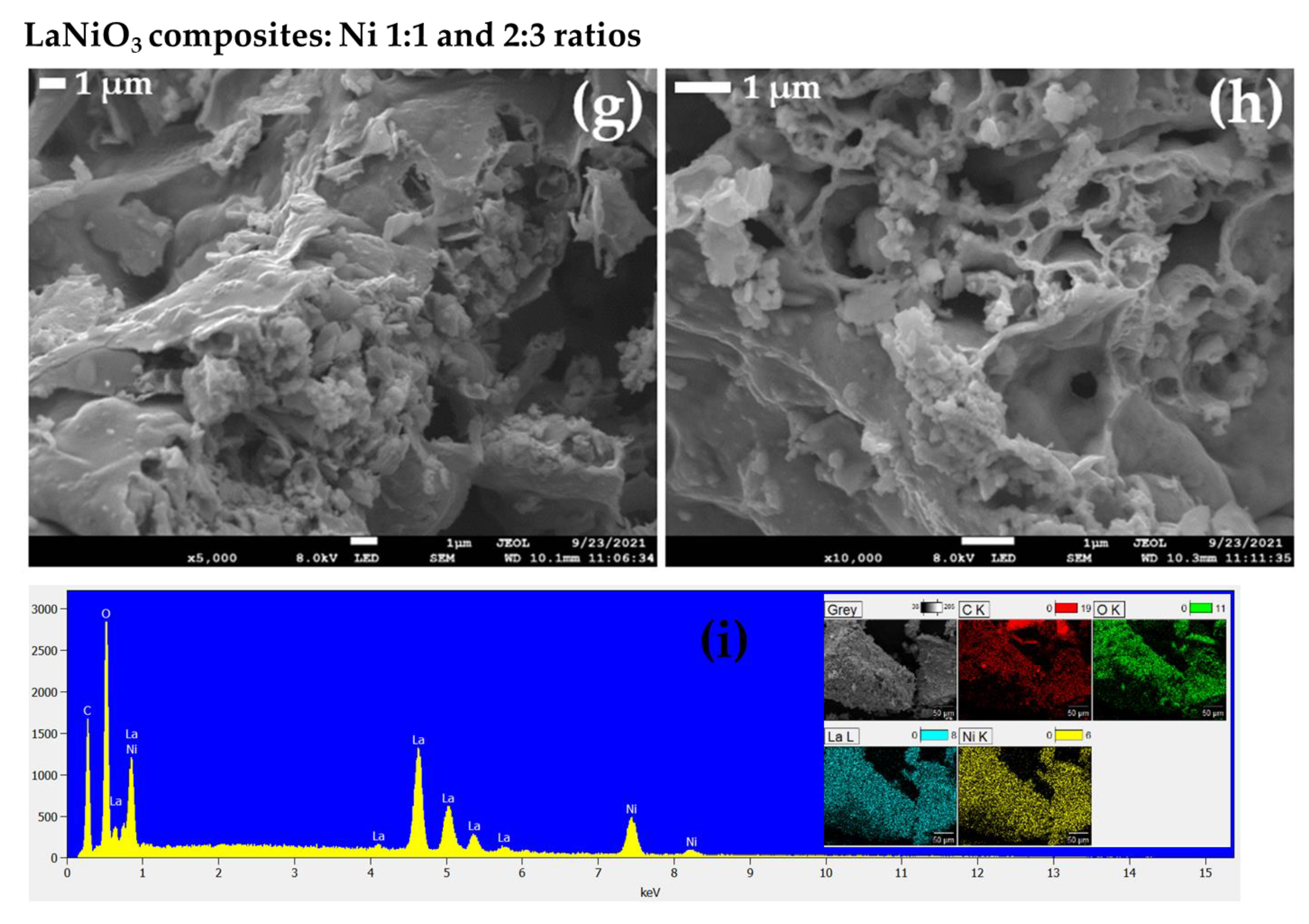
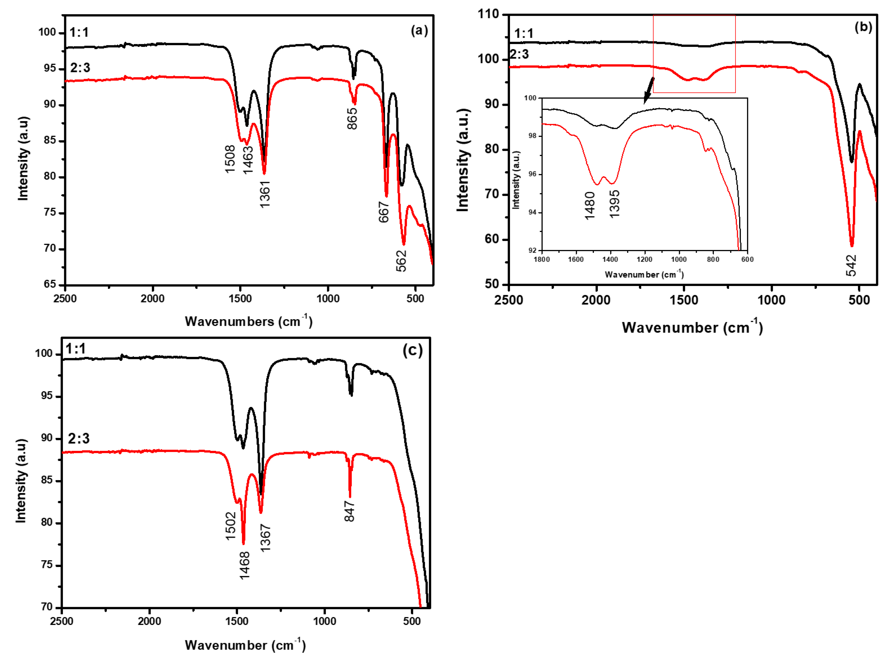
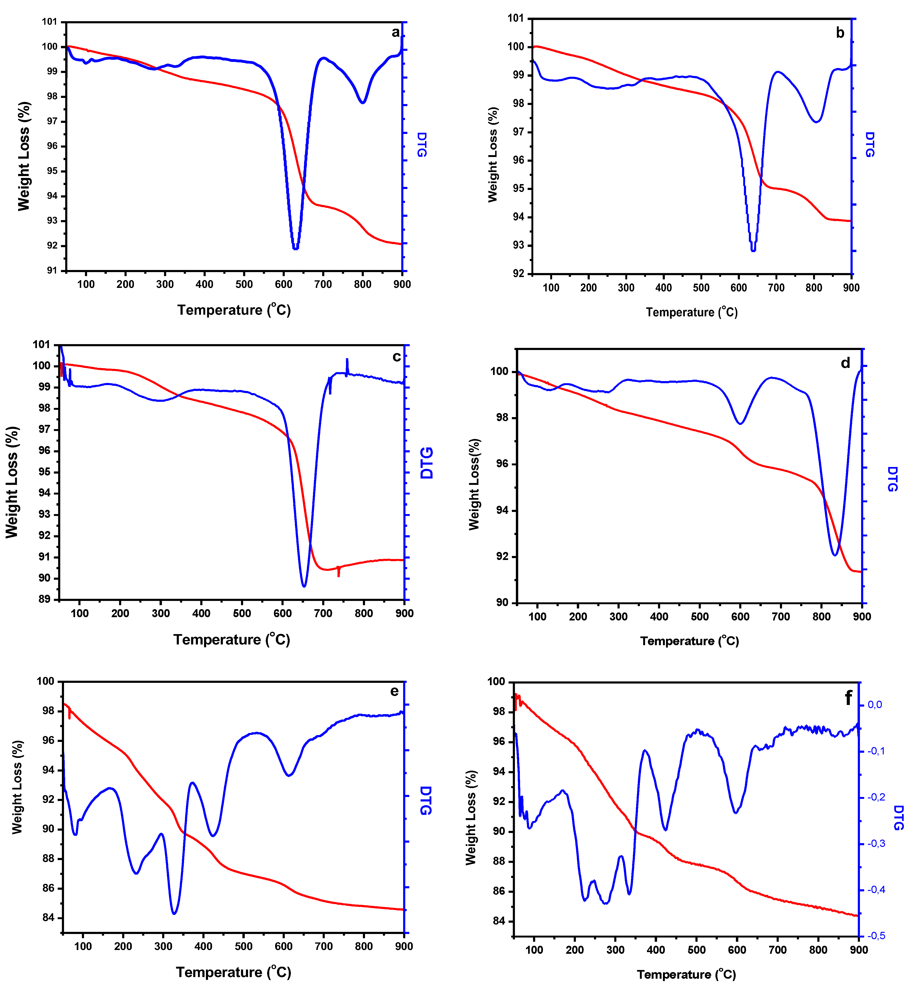
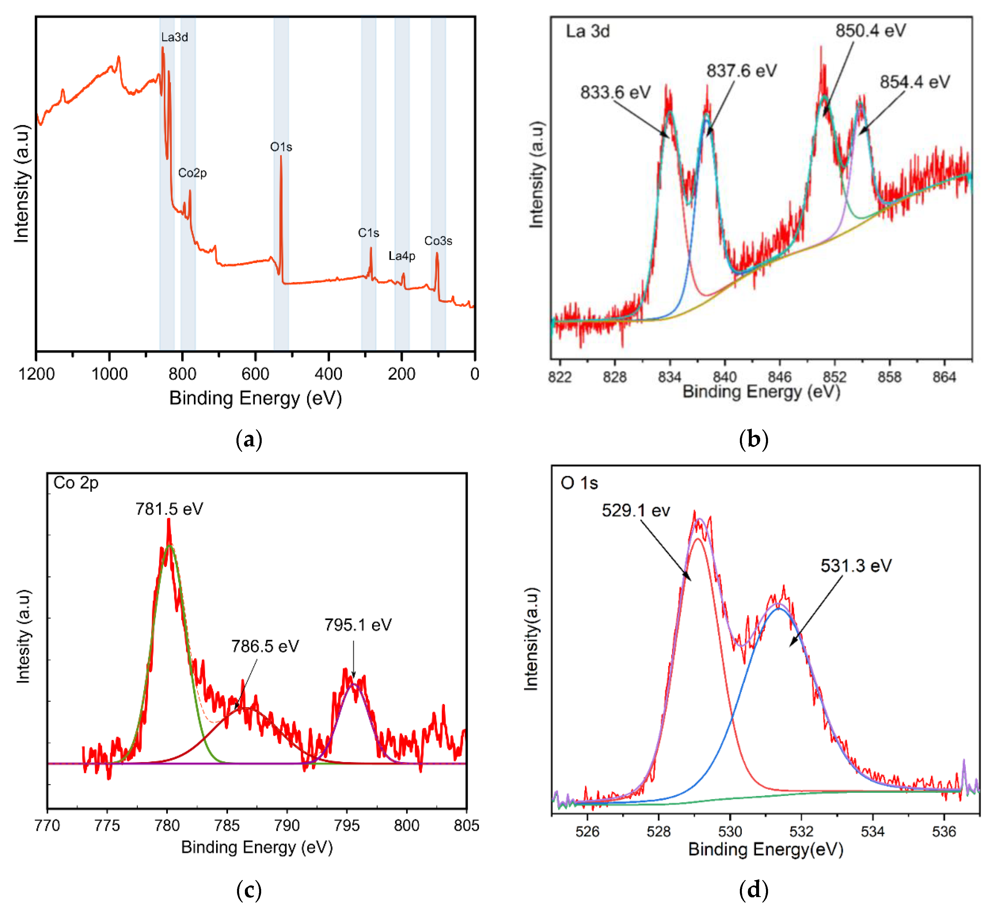
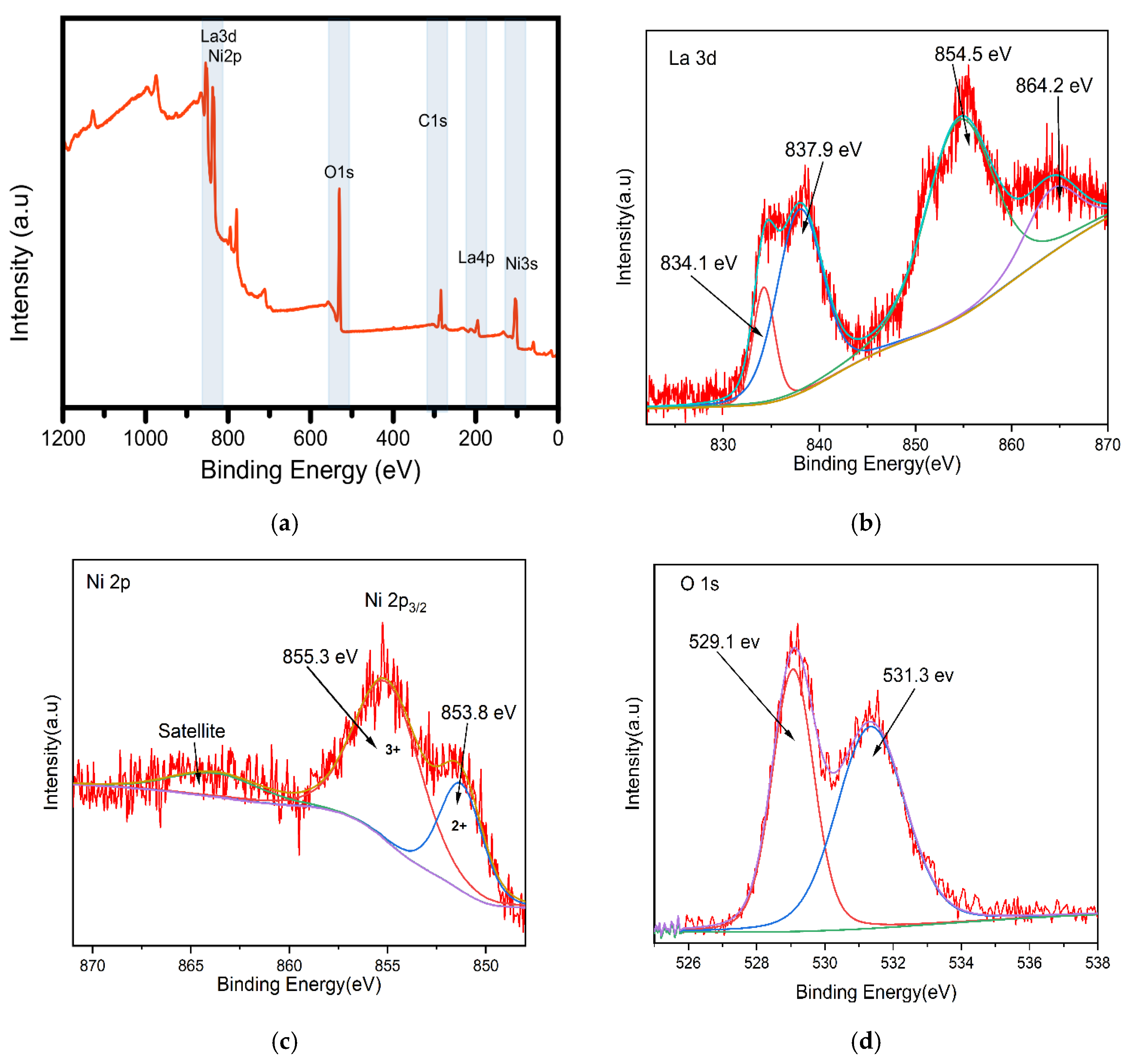
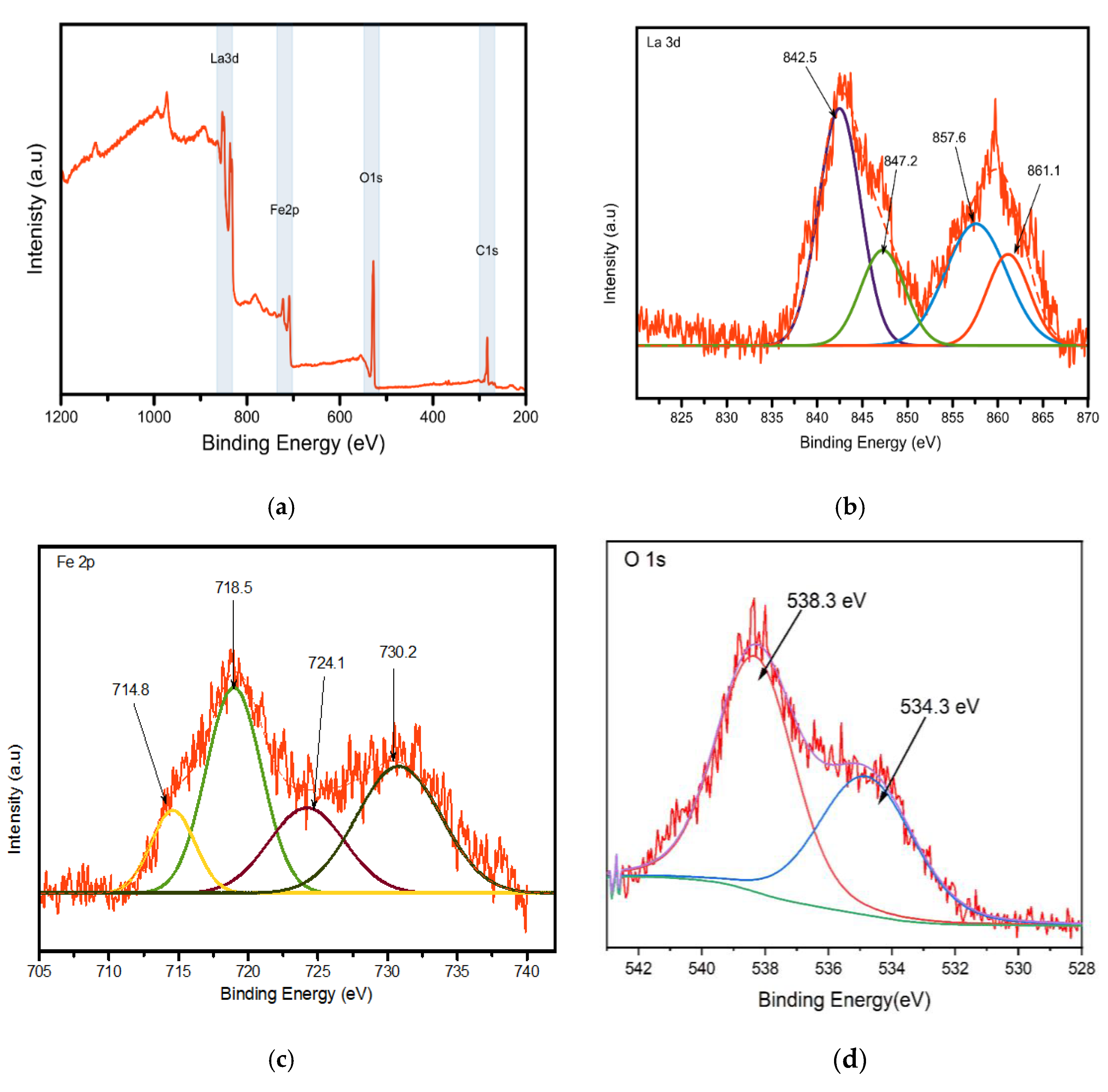
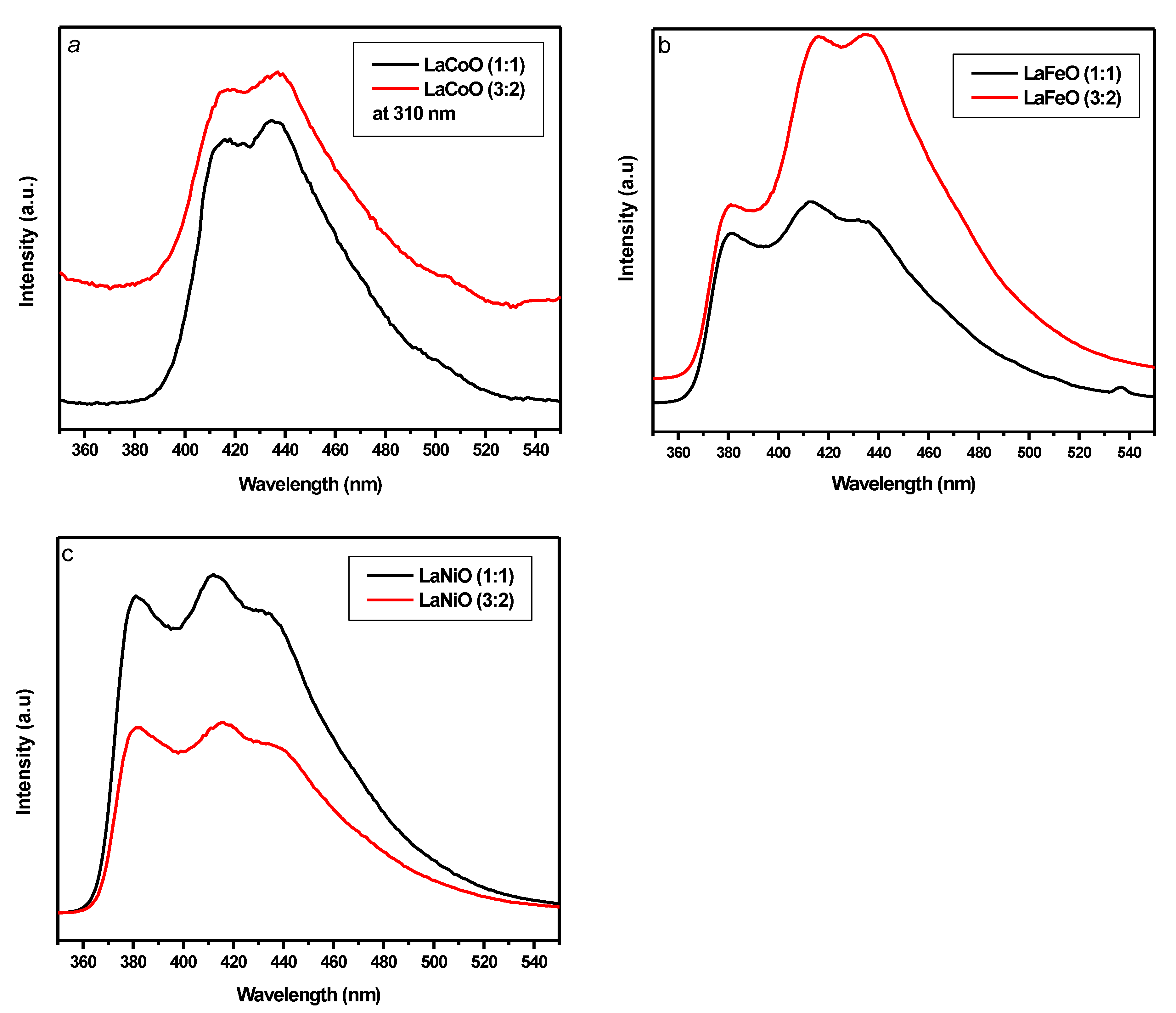
2.1. Characterization Results

The structural properties of the lanthanum mixed-oxide composites with different metal ratios were studied using the XRD technique. The samples were analyzed as-synthesized composites, which were calcined at 540 °C for 4 h. The XRD patterns for the lanthanum composites with 1:1 and 2:3 metal ratios are shown in Figure 1 and were indexed by comparing their intensities and positions with the JCPDS (Joint Committee on Powder Diffraction Standards) crystal structure database. The XRD peaks for the La-Fe composites in Figure 1a exhibited a 100% match to the lanthanum iron trioxide (LaFeO3) composite with an orthorhombic crystal structure and with the absence of LaO3 and FeO3 as impurities. This shows that there is only one phase of LaFeO3 with a crystallite size of 11.5 nm, as shown in Table 1. The LaFeO3 peaks are well-defined, and this indicates that the La-Fe composites are more crystalline compared with those of La-Ni (Figure 1b) and La-Co (Figure 1c). For La-Ni, the Rietveld refinement indicated the contributions of the obtained phases to be 85.8% lanthanum nickel trioxide (LaNiO3) and 3.3% of dilanthanum niccolate (La2NiO4), possessing crystal structures trigonal (hexagonal axes) and orthorhombic, respectively. The 10% was attributed to the presence of different phases of nickel oxide. The La-Co peaks indicated the contributions of 61% dilanthanum cobalt oxide (La2CoO4) with an orthorhombic crystal structure and an average crystallite size of 1.8 nm, while 35% is attributed to the presence of lanthanum cobalt trioxide (LaCoO3) with a cubic crystal structure and an average crystallite size of about 17 nm. Overall, the composition ratio of the lanthanum to metal ion seems to have not much of a difference in terms of phase identification as the peak contributions are similar for both the 1:1 and 2:3 ratios for all composites. The presence of mixed oxide for the LaCoO3 and LaNiO3 may be attributed to the influence of the calcination temperature which may appear to be lower. From the XRD spectra to LaCoO3 and LiNiO3 there is the presence of Co3O4 and NiO3, respectively, which were identified as different percentages in respective metal ratios (see Supplementary Materials).
Figure 2a–c shows SEM images and the EDS of LaCoO3. In La:Co molar ratio of 1:1 (Figure 2a) LaCoO3 powder consists of spherical particles that are clustered together and are highly porous forming a fibrous shape [33,34,35]. In the La:Co molar ratio of 2:3 (Figure 2b), LaCoO3 powder consists of agglomerated spherical particles forming sheet-like fragments. It was difficult to determine the particle sizes from the pictures. Elemental mapping was conducted to investigate the composition of the sample. It confirms the homogenous distribution of all the elements (La, Co, O, and C) in the sample. The intense peaks of La with energies at the 4.6 and 5.0 keV correspond to the Lα and Lβ lines, respectively. The three peaks of Co with energies 0.7, 6.9, and 7.7 keV correspond to Lα, Kα, and Kβ, respectively. The high-intensity peak of O at 0.5 keV corresponds to the oxygen Kα line [33,34]. The peak at 0.2 keV is attributed to the C tape that was used to mount the sample. Figure 2d–f shows SEM images and the EDS of LaFeO3. The SEM images reveal the agglomeration of spherical particles and porous structures forming nanosheets [36,37]. A highly porous structure is observed on the material with a high ratio of La:Fe (2:3). Figure 2f shows the EDS and mapping diagram of LaFeO3. The existence and uniform distribution of La, Fe, and O is confirmed. Figure 2g–i shows SEM images and the EDS of LaNiO3. The powders consist of agglomerated spherical particles forming nanosheets and porous [38]. The SEM images reveal a homogenous and uniform distribution of the elements of LaNiO3, which is revealed by the EDS analysis.
The FT-IR spectra of the synthesized lanthanum composites for the respective ratio composition are shown in Figure 3. The spectrum of the lanthanum cobalt oxide composite (LaCoO3) showed peaks at 1367, 567, and 647 cm−1 absorption regions. The absorption peak at 567 cm−1 was assigned to the Co-O stretching vibration mode [39] and the 667 cm−1 was assigned to the bridging vibration mode of the O-Co-O bond [40]. For the lanthanum-iron oxide composite (LaFeO3) a band at 542 cm−1 is observed and that can be attributed to an Fe-O stretching vibration being characteristic of the octahedral FeO6 group in LaFeO3 [41]. The LaFeO3 sample was exposed to ambient air, which resulted in the formation of La-carbonate species on the surface, which are assigned to the two bands at 1480 and 1395 cm−1 [42]. For the lanthanum-nickel oxide composite (LaNiO3), the peaks are observed at 1502, 1400, and 847 cm−1. The bands at 1500, 1460–1480, and 1360–1390 cm−1 are present in all the samples analyzed. The absorption peak occurring at the 1500 cm−1 region is attributed to a H-O-H bending vibration mode due to the hydroscopic absorption of moisture, which is an extrinsic feature of the perovskite material [43]. The peaks at the 1480 and 1360 cm−1 absorption regions are assigned to the O=C=O symmetric and asymmetric stretching vibrations and the C-O stretching vibration originating from the adsorption of atmospheric CO2 [44]. It is worth noting that respective ratio spectra are not entirely different from one another as they just differ in peak intensity, and this variation is attributed to the varying molar concentration composition. The band appearing in the region between 800 and 850 cm−1 is attributed to the vibrations of La–O stretching
The thermal decomposition process for each of the lanthanum composite was determined by TGA analysis, prepared at 90 min, and measured at a heating rate of 10 °C/min, as shown in Figure 4. The TGA curve showed weight loss in four different ranges for the LaFeO3 composite. The first weight loss, observed between ~0 and 360 °C, is due to the desorption of water [28]. The second weight loss, which indicated the thermal transformation of citric acid, was observed between 400 to 500 °C [6]. The third loss process between 500 and 600 °C is ascribed to the desorption of the residual hydroxyl group, while the last slight loss process at higher than 600 °C is caused by the gradual crystallization of LaFeO3 [6]. For LaNiO3, the first weight loss is observed in a temperature range of 200–400 °C and can be ascribed to the evaporation of half water molecules of crystallization [33]. The second weight loss is due to the elimination of one water molecule in the range of 400–700 °C and is associated with the thermal decomposition of Ni(OH)2 to NiO composites [33]. For LaCoO3, a weight loss occurring at 100–300 °C can be attributed to the loss of physically absorbed water and the decomposition of the citric acid. A weight loss observed in the temperature range of 390–690 °C is attributed to the decomposition of nitrates. A minor weight loss observed in the range of 690–800 °C can be assigned to the complete decomposition of oxycarbonates [26].
X-ray photoelectron spectroscopy (XPS) measurements on the nanocomposites (i.e., LaFeO3, LaNiO3, and LaCoO3) were conducted to determine the surface chemical composition and the chemical states of the respective elements in the nanocomposite. The C1 peak, located at 284.6 eV, was selected as the calibration reference for the other peaks. The overall XPS survey spectra revealed the presence of La, Co, and O (Figure 5a LaCoO3), La Ni, and O (Figure 6a of LaNiO3) and Figure 7a showed the presence of La, Fe, and O (associated with LaFeO3). The XPS survey results are well in agreement with the results of the EDX measurements presented in Figure 2. Further analysis of the high-resolution XPS spectra provided information about chemical states. In all nanocomposite high-resolution spectra of La3d, we observed two strong intensity peaks at 840.9 and 858.6 eV due to the spinning-orbit splitting energies of La 3d5/2 and 3d3/2, respectively [45,46]. This confirms the presence of La3+ in its oxide form within the lattice of the nanocomposites. The XPS spectrum of Co 2p (Figure 5c) shows two prominent peaks at the binding energies 781.5 and 795 eV, which have been attributed to Co 2p3/2 and Co 2p1/2, with a satellite peak at 786.5 eV [47]. The major peaks (i.e., Co 2p3/2 and Co 2p1/2) are ascribed to the presence of Co3+ in the lattice of the nanocomposite. As shown in Figure 6c, the Ni 2p core spectrum shows the Ni 2p3/2 peak deconvoluted into two peaks. Ni2+ had a binding energy of 853.8 eV, Ni3+ had a binding energy of 855.3 eV, while the third peak at 864.2 eV is a shake-up satellite peak [48]. Figure 7c shows the core level region of Fe 2p for sample LaFeO3, from the spectrum we observed two peaks at binding energies 714.8 eV are attributed with Fe 2p3/2, which may be due to the presence of Fe2+ [49]. The peak at 718.5 eV is associated with a shake-up satellite peak of Fe3+. The peak at 724.1 eV is associated with Fe 2p1/2 for Fe3+ [49,50]. The remaining peak at 730.2 eV may be related to the high oxidation state species (i.e., Fe4+ state) of Fe 2p1/2 [51]. This result indicates that Fe primarily contains mixed valence states of Fe3+ and Fe4+. Surface oxygen species play an important role in the photocatalytic process, so the O1s XPS spectra of all the samples can be seen and the O1s XPS peaks can be well-reproduced by three Lorentzian–Gaussian lines, which implies that there are three kinds of surface oxygen species in the samples. The binding energy at about 529.1 eV belongs to the lattice oxygen atoms, the peak at 531.28 eV can be assigned to hydroxyl oxygen (OOH), and the binding energy of 532.2–534.4 eV is ascribed to surface adsorbed oxygen (OO2). The content of the hydroxyl oxygen and the absorbed oxygen was significantly high in these La composite samples. According to the reported literature [51], the hydroxyl oxygen and the adsorbed oxygen can produce a mass of hydroxyl radicals and hydrogen peroxide, which have strong oxidization properties and are very beneficial to the photocatalytic reaction.
The photoluminescence (PL) spectra of the synthesized lanthanum nanocomposites are shown in Figure 8. PL spectroscopy has been widely used to investigate the transfer behaviour of photoinduced electrons and holes in photocatalysts, and PL emission results from the recombination of excited electrons and holes. Relatively, all nanocomposites exhibit a strong emission peak between 360 and 600 nm and this can be attributed to the self-trapped exciton (STE) luminescence [37,52]. The observed lower PL intensity for the 1:1 ratio of both the LaCoO3 and LaFeO3 nanocomposites indicates a lower recombination rate; this suggests that the nanocomposites have a higher separation efficiency of photoinduced electrons and holes, which can be attributed to their higher photocatalytic activity. The same is suggested for the LaNiO3 2:3 ratio nanocomposite, hence it has a lower PL intensity and therefore a higher photocatalytic activity compared to the LaNiO3 1:1 ratio nanocomposite. Intrinsic defects such as oxygen vacancies generated may scavenge the photoinduced electrons and holes, resulting in lower PL intensity of the nanocomposites [53]. The electrons in the CB of the nanocomposites can produce superoxide radicals (see the schematic interpretation in Scheme 1), which can be used for the degradation of organic dyes [54,55].

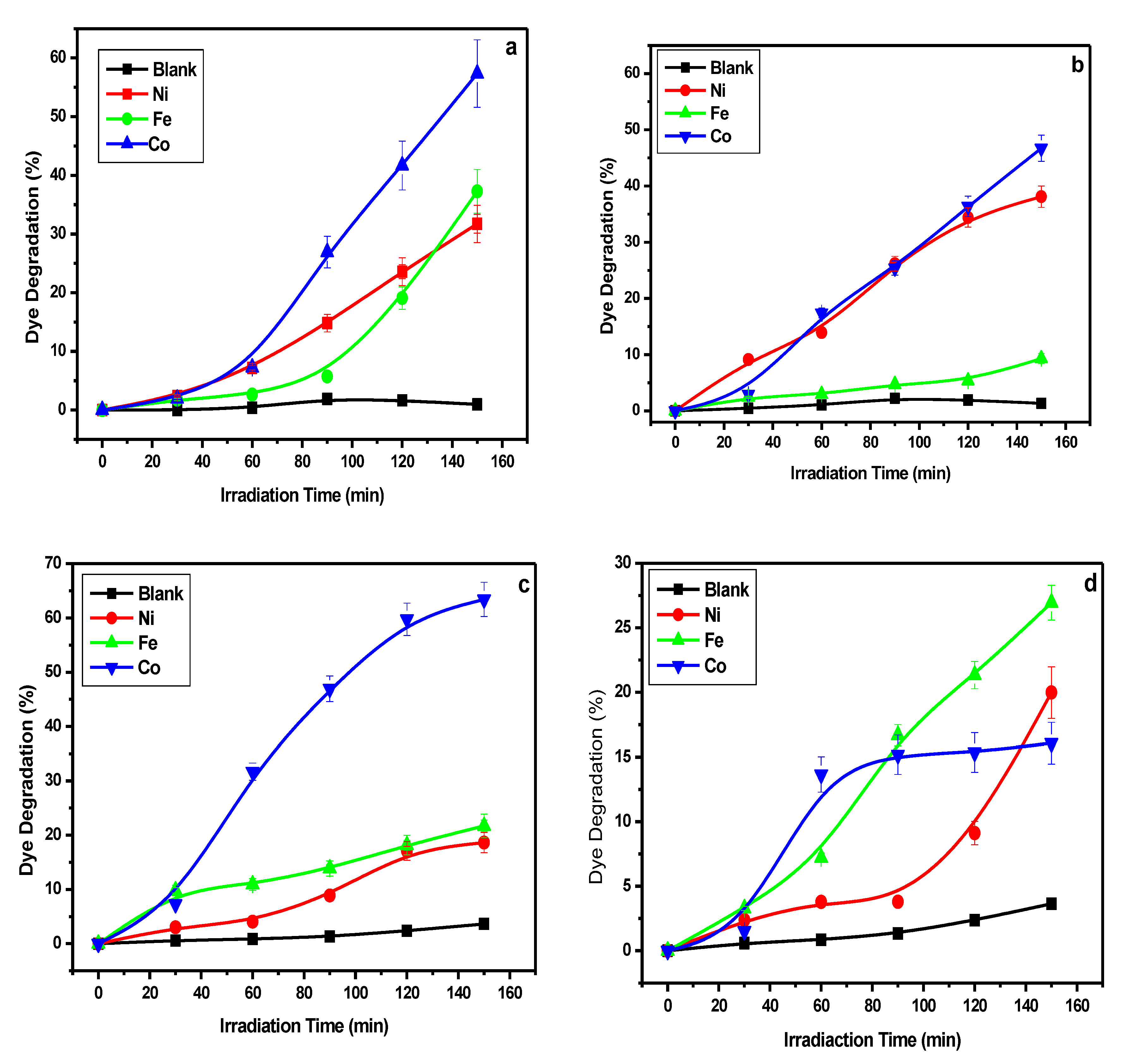
2.2. Photocatalytic Degradation

The photocatalytic degradation of MB and o-TB was studied using the synthesized La composites as photocatalysts and the photodegradation was studied under visible light with a wavelength below 420 nm. The initial concentration for MB and o-TB was 0.1 g/l in total with the catalyst dosage at 50 mg/500 mL. The degree of degradation of the respective dyes was determined by observing the changes in the dyes’ absorption spectra. A pure MB or o-TB without a La-nanocomposite catalyst was measured in the same conditions to track the photocatalysis process. The photocatalytic degradation of the specific dyes in aqueous solutions was evident, as shown by the sequential absorption spectra (Figure 9a,b) at different irradiation reaction times (i.e., from 0 to 150 min). A strong absorption peak on the UV-Vis spectrum was observed for each dye; at 630 nm for MB and 665 nm for o-TB. The absorption maxima decreased with an increase in exposure time to visible light for both dyes. This is indicative of the photodegradation of dye into oxidation products. Furthermore, there was a significant decrease in the intensity of the colour of methylene blue and o-TB with the increase in irradiation time. The MB dye comes from the thiazine class of dyes and has a sulphur-nitrogen conjugated system that acts as the chromophoric group in the MB molecules [37]. This corroborates the UV-Vis absorption spectra in Figure 9a, whereby the peak around 630 nm corresponds to the sulphur-nitrogen conjugated system. The reported mechanism shows how the sulphur-nitrogen bonds are destroyed during the degradation process and that is confirmed by the gradual decrease in peak intensity as the degradation reaction progressed as observed from the UV-Vis spectra [56,57]. Because o-TB and MB are from the same class of dyes, o-TB will follow a similar degradation pathway as MB; in addition, it also has a sulphur-nitrogen conjugated system at peak 665 nm, as observed in Figure 9b.
Figure 10 shows the photocatalytic degradation of MB and o-TB with 30% hydrogen peroxide under visible light irradiation for the respective ratios. Based on the results, it is observed that all composites appeared to have some degree of photocatalytic activity; however, the LaCoO3 composite showed to be more efficient compared to that of LaFeO3 and LaNiO3 for both dyes and at the different ratios. The respective degradation percentages are shown in Table 2, and it was observed that for o-TB, LaCoO3 showed catalytic degradation of 57% and 47% for the ratio 1:1 and 2:3, respectively, while for MB the degradation percentages are 63% and 16% for ratio 1:1 and 2:3, respectively. The LaFeO3 composite seems to be the next efficient composite with degradation percentages of 37% and 9% for the ratios 1:1 and 2:3, respectively, for o-TB, and 22% and 6% for ratios 1:1 and 2:3, respectively, for MB. Table 2 further shows a comparison of the various ratios of the composites on the catalytic degradation efficiency. It is evident that varying the molar ratio from equimolar to a different composition (2:3 in this case) causes the catalytic degradation of the composite to decrease and this trend is observed for both the LaCoO3 composite and LaFeO3 composite; however, for the LaNiO3 composite, there is an opposite trend as the molar ratios of the metal to the lanthanum are varied. Although photocatalytic activity is known to be dependent on crystallinity, surface area, bandgap energy, and morphology, the results portray a peculiar picture in which an amorphous composite (LaCoO3) has higher photocatalytic activity compared to a more crystalline composite (LaFeO3). The probable reason for the high photocatalytic activity for the La-Co composite could be from the different composition of crystal structure that possesses bigger lattice distortion, which would contribute to significant adsorption of the dye and further imposes higher photocatalytic activity, compared to that of the La-Fe composite with just a single crystal structure composition, having less lattice distortion. Another reason could be that the crystallite size of the LaCoO3 composite (Table 1) contributes towards its high photocatalytic activity as it has been proven that composites with smaller crystallite size and smaller particle size possess higher photocatalytic activity [58]. Furthermore, the excellent catalytic activity can be attributed to the transformation of Co2+/Co3+ redox pairs, as the involvement of superoxide radical ions and oxygen vacancies also favours high catalytic activity [59,60]. The LaFeO3 composite is the next efficient composite over the LaNiO3 composite and the reason for this could be that the high crystallinity of LaFeO3 takes precedence over lattice distortion, which is present in the LaNiO3 composite and is what is attributed to the LaCoO3 composite for having higher photocatalytic activity. It can also be noted that the LaFeO3 composite has a smaller crystallite size (Table 1) compared to the LaNiO3 composite, which also contributes towards its high degradation output. The high turnover frequency (TOF) for LaCO3 and LaFeO3 nanocomposites may be attributed to the La2CoO4 and LaFeO3 possessing an orthorhombic crystal structure, as it was reported that nanocomposites that possess orthorhombic crystal structures exhibit good photocatalytic activity [26]. It is for this reason that the LaFeO3 and La2CoO4 composites would have a high photocatalytic activity compared to the LaNiO3 composite since the LaFeO3 composite has a 100% orthorhombic crystal structure while La2CoO4 has a 65% orthorhombic crystal structure in its composition. The PL results showed that the LaCoO3 nanocomposites appeared to have a lower recombination rate, which suggests that the nanocomposites have a higher separation efficiency of photoinduced electrons and holes, and the presence of hydroxyl oxygen species (as shown from the XPS) can be attributed to their higher photocatalytic activity. For the LaFeO3 nanocomposite, the XPS results showed the presence of surface oxygen species that do contribute to the enhanced photocatalytic activity.
The reaction mechanisms of the photocatalytic degradation of MB and o-TB on La nanocomposites are presented in Figure 11, with Scheme 1 outlining all the reaction equations. In the reaction medium, when La-nanocomposites are irradiated with light possessing energy greater or equivalent to their bandgap, an electron from the valence band is released and elevated to the conduction band with the simultaneous generation of a hole in the valence band. The generated valence hole in the valence band, if accessible, may directly oxidise the organic dye due to the proximity of the hydroxyl groups (OH-), and adsorbed H2O molecules from the catalyst. The catalyst valence hole can react with OH- or H2O to form hydroxyl radicals (HO). In the conduction band, the excited electrons react with the dissolved oxygen present in the reaction medium (i.e, from H2O) to produce superoxide radical ions (O2●-) and upon protonation hydroperoxyl radicals (HOO) will be formed, which will further undergo protonation to yield the formation of hydrogen peroxide (H2O2). A subsequent reaction of hydrogen peroxide with hv will yield the formation of additional hydroxyl radicals (HO). The bandgap of the La nanocomposite is significant in the generation of the excited electron (e-) and the valence hole (h+). The recombination of the e- and the valence hole may render the catalyst inactive for the photocatalytic process of dye degradation.
Figure 11. Schematic representation of the organic dye degradation driven by the photocatalytic activity of La-nanocomposites.
Catalysts 12 01313 g011
Scheme 1. Reaction equations for degradation of MB and o-TB dyes on La-nanocomposites.
Catalysts 12 01313 sch001

3. Materials and Methods

3.1. Material and Chemicals

Lanthanum nitrate hexahydrate (La(NO3)3·6H2O, ≥99%), ferric nitrate nonahydrate (Fe(NO3)3·9H2O, ≥99.0%), cobalt nitrate hexahydrate (Co(NO3)3·6H2O, ≥99.0%), nickel nitrate hexahydrate (Ni(NO3)3·6H2O, ≥99.0%), absolute ethanol (C2H5OH, ≥99.9%), 30% hydrogen peroxide, and 25% ammonia solution (NH3·H2O) were purchased from Merck as well as the ortho-toluidine blue dye and the methylene blue dye. The citric acid (C6H10O8) was obtained from ChemLab supplies. All chemicals were used without further purification and ultrapure water was used for the synthesis and photocatalytic processes.

3.2. Synthesis of Lanthanum Composites

In a typical synthesis, 5 mmol La(NO3)3·6H2O (2.1621 g), 5 mmol Fe(NO3)3·9H2O (2.020 g), and 10 mmol citric acid (2.1038 g) were dissolved in 30 mL mix-solvent (H2O/EtOH 1:2) under magnetic stirring to yield a homogeneous solution. Ammonia solution was dipped into the above-mixed solution and the pH was adjusted to 6–7 until a yellow sol-gel appeared. The synthesis process was repeated for Ni(NO3)3·9H2O and Co(NO3)2·9H2O where 5 mmol (1.7636 g) and 5 mmol (1.7648 g) were added and mixed, respectively, with 5 mmol La(NO3)3·6H2O (2.1621 g) to afford a 1:1 mole ratio composition of LaNiO3 and LaCoO3 composites. For the mole ratio composition of 2:3 of the lanthanum to the metal ion, 6 mmol Fe(NO3)3·9H2O (2.4237 g), 6 mmol Ni(NO3)3·9H2O (2.1163 g), and 6 mmol Co(NO3)2·9H2O (2.1177 g) were individually mixed with 4 mmol La(NO3)3·6H2O (1.7320 g) and the synthesis was carried out under the same conditions to then generate the 2:3 mole ratio compositions of the LaFeO3, LaNiO3, and LaCoO3 composites. The obtained mixtures were dried at 90 °C for 24 h and then calcined at 540 °C for 4 h to acquire the desired fibrous phase.

3.3. Catalyst Characterization

X-ray diffraction (XRD) analysis: The calcined La-nanocomposite catalysts were prepared for X-ray diffraction (XRD) analysis using the backloading preparation method and the analysis was carried out with a 2θ angle between 5 and 90°. Diffractograms were obtained using a Malvern Panalytical Aeris diffractometer with a PIXcel detector and fixed slits with Fe-filtered Co-Kα radiation (λ = 1.7903 Å). The phases were identified using X’Pert high-score software and the relative phase amounts (weight %) were estimated using the Rietveld method.
Scanning Electron Microscopy (SEM): The morphology and elemental composition of materials were analyzed by using JEOL JSM-7800F thermal field emission SEM coupled with an Oxford Aztec 350 X-Max80 EDS under a vacuum of 9.634 × 10⁻⁵ Pa.
Fourier transform infrared (FT-IR) spectroscopy: The structural properties and functional group composition of La-nanocomposites catalysts were studied with FT-IR. The FT-IR spectra were recorded using a Spectrum Two (Perkin Elmer) spectrometer operating with a resolution of 4 cm−1. The FT-IR spectrometer was equipped with a UATR Two accessory. The FT-IR spectra were recorded in the range between 4000 and 400 cm−1 wavenumbers.
TGA measurements: The TGA studies were performed using a TGA-8000 (Perkin Elmer) analyzer using Pyris software. These experiments were performed under a nitrogen atmosphere to study the thermal stability of the La-nanocomposites catalysts. About 10 mg of the catalyst was placed in a sample holder and the nitrogen flow was adjusted to 20 mL/min. The sample was heated from 50 to 900 °C at a rate of 10 °C/min.
X-ray photoelectron spectroscopy (XPS) analysis: The XPS of the samples was performed with a Kratos AXIS spectrometer using a micro-focused monochromatic Al K(alpha) source (15mA, 0.15 eV). Data were recorded at pass energies of 150 eV for survey scans and 40 eV for high-resolution scans with 1 and 0.1 eV step sizes, respectively. The charge neutralisation was performed using low-energy electrons and agon ions. The spectra were analyzed by using Casa XPS peak fitting software version 2.3.24 and were charge corrected using the carbon 1s spectrum (adventitious carbon) at 284.8 eV as a reference.
Photoluminescence (PL) Spectroscopy Measurements: A Horiba Jobin-Yvon fluorolog-3 spectrofluorometer with a Xenon lamp as an excitation source and an HR320 detector were used to collect the photoluminescence spectra at room temperature.

3.4. Photocatalytic Activity Evaluation

Visible catalytic activity studies were performed for methylene blue (MB) and ortho-toluidine blue (o-TB) in an aqueous solution under the irradiation of a 150 W visible light lamp, wavelength λ ˃ 400 nm. For each experiment, reaction suspensions were prepared by adding 50 mg of catalyst to 50 mL aqueous MB or o-TB solution with an initial concentration of 0.1 g/l. Before photoreaction, the suspension was magnetically stirred in the dark for 30 min to attain adsorption/desorption equilibrium. The aqueous suspension was then irradiated by visible light and the reaction lasted three hours under the visible light illumination. The samples were taken at 30 min intervals regularly to be analyzed by UV spectroscopy (UV-1800 spectrophotometer, Shimadzu). The degradation (%) was calculated from the formula below, where A0 was the initial absorbance, and A was the absorbance at homologous times.
% D e g r a d a t i o n = [ A 0 A A 0 ] × 100 %

4. Conclusions

In summary, the La composites were successfully synthesized via the citric acid assisted sol-gel method at a controlled pH level. The composites were synthesized at varying molar ratios of the La metal to the different metals (i.e., Fe, Ni, Co). The results portrayed that the molar ratios play a crucial role in the activity of the composites. The lanthanum nanocomposites that have equal-molar ratios gave higher dye degradation compared to those with molar variations. The XRD and FT-IR studies confirmed that a LaFeO3 composite with a single-crystalline orthorhombic structure was prepared, as well as a composition of LaCoO3 and La2CoO4 with a cubic crystal structure and orthorhombic crystal structure, respectively. A composition of La2NiO4 and LaNiO3 was also prepared with crystal structures that were orthorhombic and trigonal (hexagonal axes), respectively. A photocatalytic reaction was conducted to test the degradation ability of the synthesized composites towards MB dye and o-TB. The reaction was monitored over a period of 3 h while using the UV-Vis to observe the degradation activity. The absorption peaks were 630 nm and 665 nm for MB and o-TB, respectively, and the results showed that La2CoO4 and LaFeO3 could serve as potential visible-light-driven photocatalytic materials as they exhibited high photocatalytic activity. This study also revealed that composites that have high percentages of orthorhombic crystal structures also tend to have high photocatalytic activity for MB and o-TB dyes.

Supplementary Materials

The following supporting information can be downloaded at: https://0-www-mdpi-com.brum.beds.ac.uk/article/10.3390/catal12111313/s1, Figure S1: XRD patterns of LaFeO3 samples, Figure S2: XRD pattern of the LaCoO3 with 2:3 metal ratio, Figure S3: XRD pattern of the LaNiO3 with 1:1 metal ratio, Figure S4: Photocatalytic degradation of MB and o-TB with 30% H2O2 under visible light irradiation, (a) o-TB, (b) MB with a metal ratio of ratio 2:4.

Author Contributions

Conceptualization T.E.T.; data curation, M.L.M.; XPS analysis, I.N.B.; PL spectroscopy and SEM analysis P.S.M. and G.L.K.; SEM-EDX interpretation P.P.M.; materials and methods, M.L.M.; supervision, T.E.T.; writing—review and editing, M.L.M., P.P.M., S.N.O. and T.E.T. All authors have read and agreed to the published version of the manuscript.

Funding

This work was supported by NRF Thutuka (TTK190427433274) and Sol Plaatje University.

Data Availability Statement

All data is available within the paper.

Conflicts of Interest

The authors declare no conflict of interest.

References

  1. Dooley, K.M.; Chen, S.-Y.; Ross, J. Stable nickel-containing catalysts for the oxidative coupling of methane. J. Catal. 1994, 145, 402–408. [Google Scholar] [CrossRef]
  2. Karimi-Maleh, H.; Moazampour, M.; Ensafi, A.A.; Mallakpour, S.; Hatami, M. An electrochemical nanocomposite modified carbon paste electrode as a sensor for simultaneous determination of hydrazine and phenol in water and wastewater samples. Environ. Sci. Pollut. Res. 2014, 21, 5879–5888. [Google Scholar] [CrossRef] [PubMed]
  3. Zhou, Z.; Xiong, W.; Zhang, Y.; Yang, D.; Wang, T.; Che, Y.; Zhao, J. Internanofiber spacing adjustment in the bundled nanofibers for sensitive fluorescence detection of volatile organic compounds. Anal. Chem. 2017, 89, 3814–3818. [Google Scholar] [CrossRef] [PubMed]
  4. Xu, Y.; Sheng, J.; Yin, X.; Yu, J.; Ding, B. Functional modification of breathable polyacrylonitrile/polyurethane/TiO2 nanofibrous membranes with robust ultraviolet resistant and waterproof performance. J. Colloid Interface Sci. 2017, 508, 508–516. [Google Scholar] [CrossRef] [PubMed]
  5. Li, Y.; Xu, Y.; Yang, W.; Shen, W.; Xue, H.; Pang, H. MOF-Derived Metal Oxide Composites for Advanced Electrochemical Energy Storage. Small 2018, 14, 1704435. [Google Scholar] [CrossRef]
  6. Fu, L.; Qu, Q.; Holze, R.; Kondratiev, V.V.; Wu, Y. Composites of metal oxides and intrinsically conducting polymers as supercapacitor electrode materials: The best of both worlds? J. Mater. Chem. A 2019, 7, 14937–14970. [Google Scholar] [CrossRef]
  7. Peng, K.; Fu, L.; Yang, H.; Ouyang, J. Perovskite LaFeO3/montmorillonite nanocomposites: Synthesis, interface characteristics and enhanced photocatalytic activity. Sci. Rep. 2016, 6, 19723. [Google Scholar] [CrossRef] [Green Version]
  8. Li, Y.; Wang, Y.; Kong, J.; Jia, H.; Wang, Z. Synthesis and characterization of carbon modified TiO2 nanotube and photocatalytic activity on methylene blue under sunlight. Appl. Surf. Sci. 2015, 344, 176–180. [Google Scholar] [CrossRef]
  9. Younas, F.; Mustafa, A.; Farooqi, Z.U.R.; Wang, X.; Younas, S.; Mohy-Ud-Din, W.; Ashir Hameed, M.; Mohsin Abrar, M.; Maitlo, A.A.; Noreen, S.; et al. Current and Emerging Adsorbent Technologies for Wastewater Treatment: Trends, Limitations, and Environmental Implications. Water 2021, 13, 215. [Google Scholar] [CrossRef]
  10. Al-Tohamy, R.; Ali, S.S.; Li, F.; Okasha, K.M.; Mahmoud, Y.A.G.; Elsamahy, T.; Jiao, H.; Fu, Y.; Sun, J. A critical review on the treatment of dye-containing wastewater: Ecotoxicological and health concerns of textile dyes and possible remediation approaches for environmental safety. Ecotoxicol. Environ. Saf. 2022, 231, 113160. [Google Scholar] [CrossRef]
  11. Torrades, F.; García-Montaño, J. Using central composite experimental design to optimize the degradation of real dye wastewater by Fenton and photo-Fenton reactions. Dye. Pigment. 2014, 100, 184–189. [Google Scholar] [CrossRef] [Green Version]
  12. Liu, L.; Chen, Z.; Zhang, J.; Shan, D.; Wu, Y.; Bai, L.; Wang, B. Treatment of industrial dye wastewater and pharmaceutical residue wastewater by advanced oxidation processes and its combination with nanocatalysts: A review. J. Water Process Eng. 2021, 42, 102122. [Google Scholar] [CrossRef]
  13. Singha, K.; Pandit, P.; Maity, S.; Sharma, S.R. Chapter 11—Harmful environmental effects for textile chemical dyeing practice. In Green Chemistry for Sustainable Textiles; Ibrahim, N., Hussain, C.M., Eds.; Woodhead Publishing: Sawston, UK, 2021; pp. 153–164. [Google Scholar] [CrossRef]
  14. Ahmad, A.; Puasa, S. Reactive dyes decolourization from an aqueous solution by combined coagulation/micellar-enhanced ultrafiltration process. Chem. Eng. J. 2007, 132, 257–265. [Google Scholar] [CrossRef]
  15. Arslan, I.; Balcioǧlu, I.A.; Bahnemann, D.W. Advanced chemical oxidation of reactive dyes in simulated dyehouse effluents by ferrioxalate-Fenton/UV-A and TiO2/UV-A processes. Dye. Pigment. 2000, 47, 207–218. [Google Scholar] [CrossRef]
  16. Mo, J.H.; Lee, Y.H.; Kim, J.; Jeong, J.Y.; Jegal, J. Treatment of dye aqueous solutions using nanofiltration polyamide composite membranes for the dye wastewater reuse. Dye. Pigment. 2008, 76, 429–434. [Google Scholar] [CrossRef]
  17. Rauf, M.; Ashraf, S.; Alhadrami, S. Photolytic oxidation of coomassie brilliant blue with H2O2. Dye. Pigment. 2005, 66, 197–200. [Google Scholar] [CrossRef]
  18. Rauf, M.; Ashraf, S.S. Fundamental principles and application of heterogeneous photocatalytic degradation of dyes in solution. Chem. Eng. J. 2009, 151, 10–18. [Google Scholar] [CrossRef]
  19. Salim, H.A.M.; Salih, S.A.M. Photodegradation study of Toluidine Blue dye in aqueous solution using magnesium oxide as a photocatalyst. Int. J. Chem. 2015, 7, 143. [Google Scholar] [CrossRef] [Green Version]
  20. Li, H.; Cao, L.; Liu, W.; Su, G.; Dong, B. Synthesis and investigation of TiO2 nanotube arrays prepared by anodization and their photocatalytic activity. Ceram. Int. 2012, 38, 5791–5797. [Google Scholar] [CrossRef]
  21. Ameta, R.; Sharma, S.; Sharma, S.; Gorana, Y. Visible Light Induced Photocatalytic Degradation of Toluidine Blue-O by Using Molybdenum Doped Titanium Dioxide. Eur. J. Adv. Eng. Technol. 2015, 2, 95–99. [Google Scholar]
  22. Sakthivel, S.; Geissen, S.-U.; Bahnemann, D.; Murugesan, V.; Vogelpohl, A. Enhancement of photocatalytic activity by semiconductor heterojunctions: α-Fe2O3, WO3 and CdS deposited on ZnO. J. Photochem. Photobiol. A Chem. 2002, 148, 283–293. [Google Scholar] [CrossRef]
  23. Jing, L.; Sun, X.J.; Xin, B.F.; Wang, B.Q.; Cai, W.; Fu, H.G. The preparation and characterization of La doped TiO2 nanoparticles and their photocatalytic activity. J. Solid State Chem. 2004, 177, 3375–3382. [Google Scholar]
  24. Wu, X.; Ding, X.; Qin, W.; He, W.; Jiang, Z. Enhanced photo-catalytic activity of TiO2 films with doped La prepared by micro-plasma oxidation method. J. Hazard. Mater. 2006, 137, 192–197. [Google Scholar] [CrossRef]
  25. Yuan, S.; Sheng, Q.; Zhang, J.; Chen, F.; Anpo, M.; Zhang, Q. Synthesis of La3+ doped mesoporous titania with highly crystallized walls. Microporous Mesoporous Mater. 2005, 79, 93–99. [Google Scholar] [CrossRef]
  26. Atribak, I.; Such-Basanez, I.; Bueno-Lopez, A.; García, A.G. Catalytic activity of La-modified TiO2 for soot oxidation by O2. Catal. Commun. 2007, 8, 478–482. [Google Scholar] [CrossRef]
  27. Thirumalairajan, S.; Girija, K.; Ganesh, I.; Mangalaraj, D.; Viswanathan, C.; Balamurugan, A.; Ponpandian, N. Controlled synthesis of perovskite LaFeO3 microsphere composed of nanoparticles via self-assembly process and their associated photocatalytic activity. Chem. Eng. J. 2012, 209, 420–428. [Google Scholar] [CrossRef]
  28. Aman, D.; Zaki, T.; Mikhail, S.; Selim, S. Synthesis of a perovskite LaNiO3 nanocatalyst at a low temperature using single reverse microemulsion. Catal. Today 2011, 164, 209–213. [Google Scholar] [CrossRef]
  29. Deng, H.; Mao, Z.; Xu, H.; Zhang, L.; Zhong, Y.; Sui, X. Synthesis of fibrous LaFeO3 perovskite oxide for adsorption of Rhodamine B. Ecotoxicol. Environ. Saf. 2019, 168, 35–44. [Google Scholar] [CrossRef]
  30. Li, Y.; Yao, S.; Wen, W.; Xue, L.; Yan, Y. Sol–gel combustion synthesis and visible-light-driven photocatalytic property of perovskite LaNiO3. J. Alloys Compd. 2010, 491, 560–564. [Google Scholar] [CrossRef]
  31. Zhong, W.; Jiang, T.; Dang, Y.; He, J.; Chen, S.-Y.; Kuo, C.-H.; Kriz, D.; Meng, Y.; Meguerdichian, A.G.; Suib, S.L. Mechanism studies on methyl orange dye degradation by perovskite-type LaNiO3-δ under dark ambient conditions. Appl. Catal. A Gen. 2018, 549, 302–309. [Google Scholar] [CrossRef]
  32. Zhao, Z. Lanthanum-containing Catalytic Materials and Their Applications in Heterogeneous Catalysis. ChemInform 2011, 42, 109–158. [Google Scholar] [CrossRef]
  33. Farhadi, S.; Sepahvand, S. Microwave-assisted solid-state decomposition of La[Co(CN)6]·5H2O precursor: A simple and fast route for the synthesis of single-phase perovskite-type LaCoO3 nanoparticles. J. Alloys Compd. 2010, 489, 586–591. [Google Scholar] [CrossRef]
  34. Gildo-Ortiz, L.; Guillén-Bonilla, H.; Rodríguez-Betancourtt, V.; Blanco-Alonso, O.; Guillén-Bonilla, A.; Santoyo-Salazar, J.; Romero-Ibarra, I.; Reyes-Gómez, J. Key processing of porous and fibrous LaCoO3 nanostructures for successful CO and propane sensing. Ceram. Int. 2018, 44, 15402–15410. [Google Scholar] [CrossRef]
  35. Thomas, J.; Anitha, P.; Thomas, T.; Thomas, N. The influence of B-site cation in LaBO3 (B = Fe, Co, Ni) perovskites on the nanomolar sensing of neurotransmitters. Sens. Actuators B Chem. 2021, 332, 129362. [Google Scholar] [CrossRef]
  36. Das, S.; Dutta, S.; Tama, A.M.; Basith, M.A. Nanostructured LaFeO3-MoS2 for efficient photodegradation and photocatalytic hydrogen evolution. Mater. Sci. Eng. B 2021, 271, 115295. [Google Scholar] [CrossRef]
  37. Pei, H.; Li, X.; Song, Y.; Zhang, M.; Wang, D.; Wu, J.; Wang, F.; Zhang, Y.; Zhao, X.; Jia, T. LaFeO3 perovskite nanoparticles for efficient capture of elemental mercury from coal-fired flue gas. Fuel 2022, 309, 122134. [Google Scholar] [CrossRef]
  38. Naveena, D.; Dhanabal, R.; Bose, A.C. Investigating the effect of La doped CuO thin film as absorber material for solar cell application. Opt. Mater. 2022, 127, 112266. [Google Scholar] [CrossRef]
  39. Estepa, L.; Daudon, M. Contribution of Fourier transform infrared spectroscopy to the identification of urinary stones and kidney crystal deposits. Biospectroscopy 1997, 3, 347–369. [Google Scholar] [CrossRef]
  40. Wu, S.-H.; Chen, D.-H. Synthesis and characterization of nickel nanoparticles by hydrazine reduction in ethylene glycol. J. Colloid Interface Sci. 2003, 259, 282–286. [Google Scholar] [CrossRef]
  41. Kashyap, S.J.; Sankannavar, R.; Madhu, G.M. Insights on the various structural, optical and dielectric characteristics of La1-xCaxFeO3 perovskite-type oxides synthesized through solution-combustion technique. Appl. Phys. A 2022, 128, 518. [Google Scholar] [CrossRef]
  42. Liu, C.; Wang, Y.; Li, X.; Li, J.; Dong, S.; Hao, H.; Tong, Y.; Zhou, Y. Highly efficient P uptake by Fe3O4 loaded amorphous Zr-La (carbonate) oxides: Electrostatic attraction, inner-sphere complexation and oxygen vacancies acceleration effect. J. Environ. Sci. 2022, 120, 18–29. [Google Scholar] [CrossRef] [PubMed]
  43. Xing, W.; Li, F.; Yan, Z.-f.; Lu, G. Synthesis and electrochemical properties of mesoporous nickel oxide. J. Power Sources 2004, 134, 324–330. [Google Scholar] [CrossRef]
  44. El-Kemary, M.; Nagy, N.; El-Mehasseb, I. Nickel oxide nanoparticles: Synthesis and spectral studies of interactions with glucose. Mater. Sci. Semicond. Process. 2013, 16, 1747–1752. [Google Scholar] [CrossRef]
  45. Ślebarski, A.; Deniszczyk, J. Experimental evidence for fractional valence of La in LaAl2: Electronic structure from x-ray photoelectron spectroscopy and band structure calculations. Phys. Rev. B 2022, 105, 245154. [Google Scholar] [CrossRef]
  46. Xiong, J.; Yu, H.; Wei, Y.; Xie, C.; Lai, K.; Zhao, Z.; Liu, J. Metal Ions (Li, Mg, Zn, Ce) Doped into La2O3 Nanorod for Boosting Catalytic Oxidative Coupling of Methane. Catalysts 2022, 12, 713. [Google Scholar] [CrossRef]
  47. Yang, Y.; Yan, X.; Liu, J.; Liu, F.; Li, Y. Reaction mechanism and microkinetics of CO catalytic combustion over Ni-doped LaCoO3 perovskite. Proc. Combust. Inst. 2022; in press. [Google Scholar] [CrossRef]
  48. Ye, C.; Wang, R.; Wang, H.; Jiang, F. The high photocatalytic efficiency and stability of LaNiO3/g-C3N4 heterojunction nanocomposites for photocatalytic water splitting to hydrogen. BMC Chem. 2020, 14, 65. [Google Scholar] [CrossRef]
  49. Xu, C.; Jin, Z.; Yang, J.; Cui, J.; Hu, J.; Li, Z.; Chen, C.; Liu, F.; Hu, R. High surface area B-doped LaFeO3/Ag/Ag3PO4 as a Z-scheme photocatalyst for facilitate phenol degradation. Colloids Surf. A Physicochem. Eng. Asp. 2022, 651, 129668. [Google Scholar] [CrossRef]
  50. Yu, J.; Wang, C.; Yuan, Q.; Yu, X.; Wang, D.; Chen, Y. Ag-Modified Porous Perovskite-Type LaFeO3 for Efficient Ethanol Detection. Nanomaterials 2022, 12, 1768. [Google Scholar] [CrossRef]
  51. Abdel-Khalek, E.K.; Motawea, M.A.; Aboelnasr, M.A.; El-Bahnasawy, H.H. Study the oxygen vacancies and Fe oxidation states in CaFeO3-δ perovskite nanomaterial. Phys. B Condens. Matter 2022, 624, 413415. [Google Scholar] [CrossRef]
  52. Chen, F.; Liu, H.; Wang, K.; Yu, H.; Dong, S.; Chen, X.; Jiang, X.; Ren, Z.; Liu, J. Synthesis and characterization of La0.825Sr0.175MnO3 nanowires. J. Phys. Condens. Matter 2005, 17, L467. [Google Scholar] [CrossRef]
  53. Veldurthi, N.K.; Bandipalli, P.; Ravi, G.; Reddy, J.R.; Palla, S.; Bhanuprakash, K.; Vithal, M. Interplay of Photoabsorption, Electronic Structure, and Recombination Rate of Charge Carriers on Visible Light Driven Photocatalytic Activity of Cu-and N-Doped Ba3V2O8. Eur. J. Inorg. Chem. 2014, 2014, 5585–5595. [Google Scholar] [CrossRef]
  54. Gao, H.; Liu, C.; Jeong, H.E.; Yang, P. Plasmon-enhanced photocatalytic activity of iron oxide on gold nanopillars. ACS Nano 2012, 6, 234–240. [Google Scholar] [CrossRef]
  55. Liu, Z.; Hou, W.; Pavaskar, P.; Aykol, M.; Cronin, S.B. Plasmon resonant enhancement of photocatalytic water splitting under visible illumination. Nano Lett. 2011, 11, 1111–1116. [Google Scholar] [CrossRef] [PubMed]
  56. Houas, A.; Lachheb, H.; Ksibi, M.; Elaloui, E.; Guillard, C.; Herrmann, J.-M. Photocatalytic degradation pathway of methylene blue in water. Appl. Catal. B Environ. 2001, 31, 145–157. [Google Scholar] [CrossRef]
  57. Huan-Ping, J. Photocatalytic degradation of methylene blue in ZIF-8. RSC Adv. 2014, 4, 54454–54462. [Google Scholar] [CrossRef]
  58. Becker, J.; Raghupathi, K.R.; Pierre, J.S.; Zhao, D.; Koodali, R.T. Tuning of the crystallite and particle sizes of ZnO nanocrystalline materials in solvothermal synthesis and their photocatalytic activity for dye degradation. J. Phys. Chem. C 2011, 115, 13844–13850. [Google Scholar] [CrossRef]
  59. Karthikeyan, S.; Boopathy, R.; Sekaran, G. In situ generation of hydroxyl radical by cobalt oxide supported porous carbon enhance removal of refractory organics in tannery dyeing wastewater. J. Colloid Interface Sci. 2015, 448, 163–174. [Google Scholar] [CrossRef]
  60. Margellou, A.; Manos, D.; Petrakis, D.; Konstantinou, I. Activation of persulfate by LaFe1-xCoxO3 perovskite catalysts for the degradation of phenolics: Effect of synthetic method and metal substitution. Sci. Total Environ. 2022, 832, 155063. [Google Scholar] [CrossRef]
Figure 1. XRD patterns of the La composites calcined at 540 °C. (a) LaFeO3, (b) LaCoO3 and (c) LaNiO3.
Catalysts 12 01313 g001
Figure 2. SEM micrographs and EDS (mapping as insets) of (ac) LaCoO3, (df) LaFeO3, and (gi) LaNiO3, calcined at 540 °C for 4 h with a ratio of 1:1 and 2:3, respectively.
Catalysts 12 01313 g002aCatalysts 12 01313 g002b
Figure 3. FT-IR spectra of the La composites for (a) LaCoO3, (b) LaFeO3, and (c) LaNiO3 with ratios of 1:1 and 2:3.
Catalysts 12 01313 g003
Figure 4. TGA analysis of the La composites with different ratios. (a) LaCoO3 (1:1), (b) LaCoO3 (2:3), (c) LaNiO3 (1:1), (d)LaNiO3 with (2:3), (e) LaFeO3 (1:1), and (f) LaFeO3 (2:3).
Catalysts 12 01313 g004
Figure 5. XPS spectra of LaCoO3 for 1:1 ratio, (a) full range survey, (b) La3d, (c) Co2P, and (d) O1s spectra.
Catalysts 12 01313 g005
Figure 6. XPS spectra of LaNiO3 for 1:1 ratio, (a) full range survey, (b) La3d, (c) Ni2P and (d) O1s spectra.
Catalysts 12 01313 g006
Figure 7. XPS spectra of LaFeO3 for 1:1 ratio, (a) full range survey, (b) La3d, (c) Fe2P, and (d) O1s spectra.
Catalysts 12 01313 g007
Figure 8. PL spectra of La composites for (a) LaCoO3, (b) LaFeO3, and (c) LaNiO3 with ratios of 1:1 and 2:3 ratios.
Catalysts 12 01313 g008
Figure 9. UV-Vis time-dependent absorption spectrum during the photocatalytic reaction of (a) MB dye, and (b) o-TB for 1:1 ratio.
Catalysts 12 01313 g009
Figure 10. Photocatalytic degradation of MB and o-TB with 30% H2O2 performed under visible light over irradiation time, (a) o-TB ratio 1:1, (b) o-TB ratio 2:3, (c) MB ratio 1:1, and (d) MB ratio 2:3.
Catalysts 12 01313 g010
Table 1. Phase composition and the average crystallite size of La nanocomposites.
La Nanocomposite%Phase Composition aAverage Crystallite Size (nm) b%Phase Composition a Average Crystallite Size (nm) b
1:12:3
LaMO3La2MO4LaMO3La2MO4LaMO3La2MO4LaMO3La2MO4
LaFeO1000.0018.2-1000.0026.3-
LaCoO35.061.01.81728.3543.222.2
LaNiO85.83.33.12.273.45.110.93.9
a Phases were estimated using the Rietveld method. b Crystallite size was determined using Scherrer’s equation.
Table 2. Overall degradation percentages for MB and o-TB.
CompositeDegradation (%)
TBO
TOF
(×1016 molecules.g−1.s−1)
Degradation (%)
MB
TOF
(1016 molecules.g−1.s−1)
La:M
1:1
La:M
2:3
La:M
1:1
La:M
2:3
La:M
1:1
La:M
2:3
La:M
1:1
La:M
2:3
LaNiO332383.824.7117202.442.88
LaFeO33794.581.1122273.163.88
LaCoO357476.805.8263169.062.30
Publisher’s Note: MDPI stays neutral with regard to jurisdictional claims in published maps and institutional affiliations.

