Earth-Abundant Electrocatalysts in Proton Exchange Membrane Electrolyzers

 , and
, and
Abstract
:1. Introduction
2. Principles of PEM Water Electrolysis
2.1. Operating Principles
2.2. Thermodynamics
2.3. Main Cell Components and Requirements
3. State-of-the-Art Devices
4. Earth-Abundant Cathode Materials
4.1. Molybdenum Sulfide, MoS2
4.2. Nickel Phosphide, Ni2P
4.3. Iron Sulfides, FexSy
4.4. Carbon-Based Materials
4.5. Co-Clathrochelates
4.6. Density Functional Theory (DFT) for HER Catalysts
5. Earth-Abundant Anode Materials
6. Summary, Challenges, Perspectives and Future Directions
Supplementary Materials
Author Contributions
Funding
Acknowledgments
Conflicts of Interest
References
- IEA. Key World Energy Statistics. Available online: www.iea.org/statistics (accessed on 30 September 2018).
- Jakob, M.; Hilaire, J. Unburnable fossil-fuel reserves. Nature 2015, 517, 150–152. [Google Scholar] [CrossRef] [PubMed]
- McGlade, C.; Ekins, P. The geographical distribution of fossil fuels unused when limiting global warming to 2 °C. Nature 2015, 517, 187–190. [Google Scholar] [CrossRef] [PubMed] [Green Version]
- Abas, N.; Kalair, A.; Khan, N. Review of fossil fuels and future energy technologies. Futures 2015, 69, 31–49. [Google Scholar] [CrossRef]
- Kirubakaran, A.; Jain, S.; Nema, R.K. A review on fuel cell technologies and power electronic interface. Renew. Sustain. Energy Rev. 2009, 13, 2430–2440. [Google Scholar] [CrossRef]
- Zeng, K.; Zhang, D. Recent progress in alkaline water electrolysis for hydrogen production and applications. Prog. Energy Combust. Sci. 2010, 36, 307–326. [Google Scholar] [CrossRef]
- Bezerra, C.W.B.; Zhang, L.; Lee, K.; Liu, H.; Marques, A.L.B.; Marques, E.P.; Wang, H.; Zhang, J. A review of Fe–N/C and Co–N/C catalysts for the oxygen reduction reaction. Electrochim. Acta 2008, 53, 4937–4951. [Google Scholar] [CrossRef]
- Cipriani, G.; Di Dio, V.; Genduso, F.; La Cascia, D.; Liga, R.; Miceli, R.; Ricco Galluzzo, G. Perspective on hydrogen energy carrier and its automotive applications. Int. J. Hydrogen Energy 2014, 39, 8482–8494. [Google Scholar] [CrossRef]
- Ghosh, P.C.; Emonts, B.; Janßen, H.; Mergel, J.; Stolten, D. Ten years of operational experience with a hydrogen-based renewable energy supply system. Solar Energy 2003, 75, 469–478. [Google Scholar] [CrossRef]
- Rand, D.A.J. A journey on the electrochemical road to sustainability. J. Solid State Electrochem. 2011, 15, 1579–1622. [Google Scholar] [CrossRef]
- Acar, C.; Dincer, I. Comparative assessment of hydrogen production methods from renewable and non-renewable sources. Int. J. Hydrogen Energy 2014, 39, 1–12. [Google Scholar] [CrossRef]
- Balat, M.; Balat, M. Political, economic and environmental impacts of biomass-based hydrogen. Int. J. Hydrogen Energy 2009, 34, 3589–3603. [Google Scholar] [CrossRef]
- Holladay, J.D.; Hu, J.; King, D.L.; Wang, Y. An overview of hydrogen production technologies. Catal. Today 2009, 139, 244–260. [Google Scholar] [CrossRef]
- Aho, A.; Antonietti, M.; Arndt, S.; Behrens, M.; Bill, E.; Brandner, A.; Centi, G.; Claus, P.; Cox, N.; DeBeer, S. Chemical Energy Storage; De Gruyter: Berlin, Germany, 2013. [Google Scholar]
- Grubb, W.T. Batteries with Solid Ion Exchange Electrolytes I. Secondary Cells Employing Metal Electrodes. J. Electrochem. Soc. 1959, 106, 275–278. [Google Scholar] [CrossRef]
- Grubb, W.T.; Niedrach, L.W. Batteries with Solid Ion-Exchange Membrane Electrolytes II. Low-Temperature Hydrogen-Oxygen Fuel Cells. J. Electrochem. Soc. 1960, 107, 131–135. [Google Scholar] [CrossRef]
- Russell, J.H.; Nuttal, L.J.; Fickett, A.P. Hydrogen Generation by Solid Polymer Electrolyte Water Electrolysis. Am. Chem.Soc. Div. Fuel Chem. Prepr. 1973, 18, 24–40. [Google Scholar]
- Sapountzi, F.M.; Gracia, J.M.; Fredriksson, H.O.; Niemantsverdriet, J.H. Electrocatalysts for the generation of hydrogen, oxygen and synthesis gas. Prog. Energy Combust. 2017, 58, 1–35. [Google Scholar] [CrossRef]
- Harriman, A. Prospects for conversion of solar energy into chemical fuels: The concept of a solar fuels industry. Philos. Trans. R. Soc. A Math. Phys. Eng. Sci. 2013, 371, 20110415. [Google Scholar] [CrossRef]
- Yu, E.H.; Wang, X.; Krewer, U.; Li, L.; Scott, K. Direct oxidation alkaline fuel cells: From materials to systems. Energy Environ. Sci. 2012, 5, 5668–5680. [Google Scholar] [CrossRef]
- James, B.; Colella, W.; Moton, J.; Saur, G.; Ramsden, T. PEM Electrolysis H2A Production Case Study Documentation; National Renewable Energy Lab. (NREL): Golden, CO, USA, 2013.
- Bertuccioli, L.; Chan, A.; Hart, D.; Lehner, F.; Madden, B.; Standen, E. Study on Development of Water Electrolysis in the EU: Fuel Cells and Hydrogen Joint Undertaking; E4tech Sàrl with Element Energy Ltd.: Brussels, Switzerland, 2014; pp. 1–160. [Google Scholar]
- Lymperopoulos, N. FCH JU. Support to Electrolysis for Energy Application. Presented at the ICE 2017, Copenhagen, Denmark, 12–15 June 2017. [Google Scholar]
- Detz, R.J.; Reek, J.N.H.; van der Zwaan, B.C.C. The future of solar fuels: When could they become competitive? Energy Environ. Sci. 2018, 11, 1653–1669. [Google Scholar] [CrossRef]
- Santos, S.O.; Collodi, G.; Azzaro, G.; Ferrari, N. Techno-Economic Evaluation of SMR Based Standalone (Merchant) Hydrogen Plant with CCS; IEAGHG Technical Report: Hatherley Lane, Cheltenham, UK, 2017. [Google Scholar]
- Paoli, E.A.; Masini, F.; Frydendal, R.; Deiana, D.; Schlaup, C.; Malizia, M.; Hansen, T.W.; Horch, S.; Stephens, I.E.L.; Chorkendorff, I. Oxygen evolution on well-characterized mass-selected Ru and RuO2 nanoparticles. Chem. Sci. 2015, 6, 190–196. [Google Scholar] [CrossRef]
- Fabbri, E.; Habereder, A.; Waltar, K.; Kötz, R.; Schmidt, T.J. Developments and perspectives of oxide-based catalysts for the oxygen evolution reaction. Catal. Sci. Technol. 2014, 4, 3800–3821. [Google Scholar] [CrossRef] [Green Version]
- Xia, X.; Zhu, C.; Luo, J.; Zeng, Z.; Guan, C.; Ng, C.F.; Zhang, H.; Fan, H.J. Synthesis of Free-Standing Metal Sulfide Nanoarrays via Anion Exchange Reaction and Their Electrochemical Energy Storage Application. Small 2013, 10, 766–773. [Google Scholar] [CrossRef] [PubMed]
- You, B.; Jiang, N.; Sheng, M.; Sun, Y. Microwave vs. solvothermal synthesis of hollow cobalt sulfide nanoprisms for electrocatalytic hydrogen evolution and supercapacitors. Chem. Commun. 2015, 51, 4252–4255. [Google Scholar] [CrossRef] [PubMed]
- Tran, P.D.; Chiam, S.Y.; Boix, P.P.; Ren, Y.; Pramana, S.S.; Fize, J.; Artero, V.; Barber, J. Novel cobalt/nickel–tungsten-sulfide catalysts for electrocatalytic hydrogen generation from water. Energy Environ. Sci. 2013, 6, 2452–2459. [Google Scholar] [CrossRef]
- Wu, Z.; Fang, B.; Bonakdarpour, A.; Sun, A.; Wilkinson, D.P.; Wang, D. WS2 nanosheets as a highly efficient electrocatalyst for hydrogen evolution reaction. Appl. Catal. B Environ. 2012, 125, 59–66. [Google Scholar] [CrossRef]
- Qin, Z.; Chen, Y.; Huang, Z.; Su, J.; Diao, Z.; Guo, L. Composition-Dependent Catalytic Activities of Noble-Metal-Free NiS/Ni3S4 for Hydrogen Evolution Reaction. J. Phys. Chem. C 2016, 120, 14581–14589. [Google Scholar] [CrossRef]
- Kibsgaard, J.; Jaramillo, T.F.; Besenbacher, F. Building an appropriate active-site motif into a hydrogen-evolution catalyst with thiomolybdate [Mo3S13]2− clusters. Nat. Chem. 2014, 6, 248–253. [Google Scholar] [CrossRef]
- Shi, Y.; Zhang, B. Recent advances in transition metal phosphide nanomaterials: Synthesis and applications in hydrogen evolution reaction. Chem. Soc. Rev. 2016, 45, 1529–1541. [Google Scholar] [CrossRef]
- Anantharaj, S.; Ede, S.R.; Sakthikumar, K.; Karthick, K.; Mishra, S.; Kundu, S. Recent Trends and Perspectives in Electrochemical Water Splitting with an Emphasis on Sulfide, Selenide, and Phosphide Catalysts of Fe, Co, and Ni: A Review. ACS Catal. 2016, 6, 8069–8097. [Google Scholar] [CrossRef]
- Callejas, J.F.; McEnaney, J.M.; Read, C.G.; Crompton, J.C.; Biacchi, A.J.; Popczun, E.J.; Gordon, T.R.; Lewis, N.S.; Schaak, R.E. Electrocatalytic and Photocatalytic Hydrogen Production from Acidic and Neutral-pH Aqueous Solutions Using Iron Phosphide Nanoparticles. ACS Nano 2014, 8, 11101–11107. [Google Scholar] [CrossRef]
- Xiao, P.; Chen, W.; Wang, X. A Review of Phosphide-Based Materials for Electrocatalytic Hydrogen Evolution. Adv. Energy Mater. 2015, 5, 1500985. [Google Scholar] [CrossRef]
- Henkes, A.E.; Vasquez, Y.; Schaak, R.E. Converting Metals into Phosphides: A General Strategy for the Synthesis of Metal Phosphide Nanocrystals. J. Am. Chem. Soc. 2007, 129, 1896–1897. [Google Scholar] [CrossRef] [PubMed]
- Park, J.; Koo, B.; Yoon, K.Y.; Hwang, Y.; Kang, M.; Park, J.-G.; Hyeon, T. Generalized Synthesis of Metal Phosphide Nanorods via Thermal Decomposition of Continuously Delivered Metal−Phosphine Complexes Using a Syringe Pump. J. Am. Chem. Soc. 2005, 127, 8433–8440. [Google Scholar] [CrossRef] [PubMed]
- Greeley, J.; Jaramillo, T.F.; Bonde, J.; Chorkendorff, I.; Nørskov, J.K. Computational high-throughput screening of electrocatalytic materials for hydrogen evolution. Nat. Mater. 2006, 5, 909–913. [Google Scholar] [CrossRef] [PubMed]
- McKone, J.R.; Sadtler, B.F.; Werlang, C.A.; Lewis, N.S.; Gray, H.B. Ni-Mo Nanopowders for Efficient Electrochemical Hydrogen Evolution. ACS Catal. 2013, 3, 166–169. [Google Scholar] [CrossRef]
- Jaramillo, T.F.; Jørgensen, K.P.; Bonde, J.; Nielsen, J.H.; Horch, S.; Chorkendorff, I. Identification of Active Edge Sites for Electrochemical H2 Evolution from MoS2 Nanocatalysts. Science 2007, 317, 100–102. [Google Scholar] [CrossRef] [PubMed]
- Faber, M.S.; Dziedzic, R.; Lukowski, M.A.; Kaiser, N.S.; Ding, Q.; Jin, S. High-Performance Electrocatalysis Using Metallic Cobalt Pyrite (CoS2) Micro- and Nanostructures. J. Am. Chem. Soc. 2014, 136, 10053–10061. [Google Scholar] [CrossRef]
- Zou, X.; Huang, X.; Goswami, A.; Silva, R.; Sathe, B.R.; Mikmeková, E.; Asefa, T. Cobalt-Embedded Nitrogen-Rich Carbon Nanotubes Efficiently Catalyze Hydrogen Evolution Reaction at All pH Values. Angew. Chem. Int. Ed. 2014, 53, 4372–4376. [Google Scholar] [CrossRef]
- Zhou, W.; Zhou, J.; Zhou, Y.; Lu, J.; Zhou, K.; Yang, L.; Tang, Z.; Li, L.; Chen, S. N-Doped Carbon-Wrapped Cobalt Nanoparticles on N-Doped Graphene Nanosheets for High-Efficiency Hydrogen Production. Chem. Mater. 2015, 27, 2026–2032. [Google Scholar] [CrossRef]
- Zhou, W.; Xiong, T.; Shi, C.; Zhou, J.; Zhou, K.; Zhu, N.; Li, L.; Tang, Z.; Chen, S. Bioreduction of Precious Metals by Microorganism: Efficient Gold@N-Doped Carbon Electrocatalysts for the Hydrogen Evolution Reaction. Angew. Chem. Int. Ed. 2016, 55, 8416–8420. [Google Scholar] [CrossRef]
- Xu, Y.; Wu, R.; Zhang, J.; Shi, Y.; Zhang, B. Anion-exchange synthesis of nanoporous FeP nanosheets as electrocatalysts for hydrogen evolution reaction. Chem. Commun. 2013, 49, 6656–6658. [Google Scholar] [CrossRef] [PubMed]
- Xu, R.; Wu, R.; Shi, Y.; Zhang, J.; Zhang, B. Ni3Se2 nanoforest/Ni foam as a hydrophilic, metallic, and self-supported bifunctional electrocatalyst for both H2 and O2 generations. Nano Energy 2016, 24, 103–110. [Google Scholar] [CrossRef]
- Lu, Z.; Zhu, W.; Yu, X.; Zhang, H.; Li, Y.; Sun, X.; Wang, X.; Wang, H.; Wang, J.; Luo, J.; et al. Ultrahigh Hydrogen Evolution Performance of Under-Water “Superaerophobic” MoS2 Nanostructured Electrodes. Adv. Mater. 2014, 26, 2683–2687. [Google Scholar] [CrossRef] [PubMed]
- Li, F.; Li, J.; Lin, X.; Li, X.; Fang, Y.; Jiao, L.; An, X.; Fu, Y.; Jin, J.; Li, R. Designed synthesis of multi-walled carbon nanotubes@Cu@MoS2 hybrid as advanced electrocatalyst for highly efficient hydrogen evolution reaction. J. Power Sources 2015, 300, 301–308. [Google Scholar] [CrossRef]
- Yang, L.; Zhou, W.; Hou, D.; Zhou, K.; Li, G.; Tang, Z.; Li, L.; Chen, S. Porous metallic MoO2-supported MoS2 nanosheets for enhanced electrocatalytic activity in the hydrogen evolution reaction. Nanoscale 2015, 7, 5203–5208. [Google Scholar] [CrossRef] [PubMed]
- Zhou, H.; Wang, Y.; He, R.; Yu, F.; Sun, J.; Wang, F.; Lan, Y.; Ren, Z.; Chen, S. One-step synthesis of self-supported porous NiSe2/Ni hybrid foam: An efficient 3D electrode for hydrogen evolution reaction. Nano Energy 2016, 20, 29–36. [Google Scholar] [CrossRef]
- Sardar, K.; Petrucco, E.; Hiley, C.I.; Sharman, J.D.B.; Wells, P.P.; Russell, A.E.; Kashtiban, R.J.; Sloan, J.; Walton, R.I. Water-Splitting Electrocatalysis in Acid Conditions Using Ruthenate-Iridate Pyrochlores. Angew. Chem. Int. Ed. 2014, 53, 10960–10964. [Google Scholar] [CrossRef] [Green Version]
- Carmo, M.; Fritz, D.L.; Mergel, J.; Stolten, D. A comprehensive review on PEM water electrolysis. Int. J. Hydrogen Energy 2013, 38, 4901–4934. [Google Scholar] [CrossRef]
- Anantharaj, S.; Ede, S.R.; Karthick, K.; Sam Sankar, S.; Sangeetha, K.; Karthik, P.E.; Kundu, S. Precision and correctness in the evaluation of electrocatalytic water splitting: Revisiting activity parameters with a critical assessment. Energy Environ. Sci. 2018, 11, 744–771. [Google Scholar] [CrossRef]
- Kreuter, W.; Hofmann, H. Electrolysis: The important energy transformer in a world of sustainable energy. Int. J. Hydrogen Energy 1998, 23, 661–666. [Google Scholar] [CrossRef]
- Leroy, R.L. Industrial Water Electrolysis - Present and Future. Int. J. Hydrogen Energy 1983, 8, 401–417. [Google Scholar] [CrossRef]
- Bessarabov, D.; Wang, H.; Li, H.; Zhao, N. PEM Electrolysis for Hydrogen Production: Principles and Applications, 1st ed.; Taylor & Francis: Boca Raton, FL, USA, 2015; ISBN 9781482252323. [Google Scholar]
- Ayers, K.E.; Anderson, E.B.; Capuano, C.B.; Carter, B.D.; Dalton, L.T.; Hanlon, G.; Manco, J.; Niedzwiecki, M. Research Advances Towards Low Cost, High Efficiency PEM Electrolysis. ECS Trans. 2010, 33, 3–15. [Google Scholar]
- Grigoriev, S.A.; Porembskiy, V.I.; Korobtsev, S.V.; Fateev, V.N.; Aupretre, F.; Millet, P. High-pressure PEM water electrolysis and corresponding safety issues. Int. J. Hydrogen Energy 2011, 36, 2721–2728. [Google Scholar] [CrossRef]
- Marangio, F.; Santarelli, M.; Cali, M. Theoretical model and experimental analysis of a high pressure PEM water electrolyser for hydrogen production. Int. J. Hydrogen Energy 2009, 34, 1143–1158. [Google Scholar] [CrossRef]
- Millet, P.; Ngameni, R.; Grigoriev, S.A.; Mbemba, N.; Brisset, F.; Ranjbari, A.; Etievant, C. PEM water electrolyzers: From electrocatalysis to stack development. Int. J. Hydrogen Energy 2010, 35, 5043–5052. [Google Scholar] [CrossRef]
- van de Krol, R.; Grätzel, M. Photoelectrochemical Hydrogen Production; Springer: New York, NY, USA, 2012; pp. 220–221. [Google Scholar]
- Bockris, J.O.M. Kinetics of Activation Controlled Consecutive Electrochemical Reactions: Anodic Evolution of Oxygen. J. Chem. Phys. 1956, 24, 817–827. [Google Scholar] [CrossRef]
- Durst, J.; Siebel, A.; Simon, C.; Hasche, F.; Herranz, J.; Gasteiger, H.A. New insights into the electrochemical hydrogen oxidation and evolution reaction mechanism. Energy Environ. Sci. 2014, 7, 2255–2260. [Google Scholar] [CrossRef] [Green Version]
- Pantani, O.; Anxolabehere-Mallart, E.; Aukauloo, A.; Millet, P. Electroactivity of cobalt and nickel glyoximes with regard to the electro-reduction of protons into molecular hydrogen in acidic media. Electrochem. Commun. 2007, 9, 54–58. [Google Scholar] [CrossRef]
- Ahn, J.; Holze, R. Bifunctional Electrodes for an Integrated Water-Electrolysis and Hydrogen Oxygen Fuel-Cell with a Solid Polymer Electrolyte. J. Appl. Electrochem. 1992, 22, 1167–1174. [Google Scholar] [CrossRef]
- Grigoriev, S.A.; Porembsky, V.I.; Fateev, V.N. Pure hydrogen production by PEM electrolysis for hydrogen energy. Int. J. Hydrogen Energy 2006, 31, 171–175. [Google Scholar] [CrossRef]
- Millet, P.; Dragoe, D.; Grigoriev, S.; Fateev, V.; Etievant, C. GenHyPEM: A research program on PEM water electrolysis supported by the European Commission. Int. J. Hydrogen Energy 2009, 34, 4974–4982. [Google Scholar] [CrossRef]
- Millet, P.; Pineri, M.; Durand, R. New solid polymer electrolyte composites for water electrolysis. J. Appl. Electrochem. 1989, 19, 162–166. [Google Scholar] [CrossRef]
- Chi, J.; Yu, H. Water electrolysis based on renewable energy for hydrogen production. Chin. J. Catal. 2018, 39, 390–394. [Google Scholar] [CrossRef]
- Ogawa, T.; Takeuchi, M.; Kajikawa, Y. Analysis of Trends and Emerging Technologies in Water Electrolysis Research Based on a Computational Method: A Comparison with Fuel Cell Research. Sustainability 2018, 10, 478. [Google Scholar] [CrossRef]
- Siracusano, S.; Van Dijk, N.; Payne-Johnson, E.; Baglio, V.; Aricò, A.S. Nanosized IrOx and IrRuOx electrocatalysts for the O2 evolution reaction in PEM water electrolysers. Appl. Catal. B Environ. 2015, 164, 488–495. [Google Scholar] [CrossRef]
- Cheng, J.; Zhang, H.; Chen, G.; Zhang, Y. Study of IrxRu1−xO2 oxides as anodic electrocatalysts for solid polymer electrolyte water electrolysis. Electrochim. Acta 2009, 54, 6250–6256. [Google Scholar] [CrossRef]
- Kötz, R.; Stucki, S.; Scherson, D.; Kolb, D. In-situ identification of RuO4 as the corrosion product during oxygen evolution on ruthenium in acid media. J. Electroanal. Chem. Interfacial Electrochem. 1984, 172, 211–219. [Google Scholar] [CrossRef]
- Cherevko, S. Stability and dissolution of electrocatalysts: Building the bridge between model and “real world” systems. Curr. Opin. Electrochem. 2018, 8, 118–125. [Google Scholar] [CrossRef]
- Li, G.; Yu, H.; Song, W.; Wang, X.; Li, Y.; Shao, Z.; Yi, B. Zeolite-templated IrxRu1−xO2 electrocatalysts for oxygen evolution reaction in solid polymer electrolyte water electrolyzers. Int. J. Hydrogen Energy 2012, 37, 16786–16794. [Google Scholar] [CrossRef]
- Corona-Guinto, J.; Cardeño-García, L.; Martínez-Casillas, D.; Sandoval-Pineda, J.M.; Tamayo-Meza, P.; Silva-Casarin, R.; González-Huerta, R. Performance of a PEM electrolyzer using RuIrCoOx electrocatalysts for the oxygen evolution electrode. Int. J. Hydrogen Energy 2013, 38, 12667–12673. [Google Scholar] [CrossRef]
- Marshall, A.T.; Sunde, S.; Tsypkin, M.; Tunold, R. Performance of a PEM water electrolysis cell using IrxRuyTazO2 electrocatalysts for the oxygen evolution electrode. Int. J. Hydrogen Energy 2007, 32, 2320–2324. [Google Scholar] [CrossRef]
- Kadakia, K.; Datta, M.K.; Velikokhatnyi, O.I.; Jampani, P.; Park, S.K.; Chung, S.J.; Kumta, P.N. High performance fluorine doped (Sn, Ru) O2 oxygen evolution reaction electro-catalysts for proton exchange membrane based water electrolysis. J. Power Sources 2014, 245, 362–370. [Google Scholar] [CrossRef]
- Ghadge, S.D.; Patel, P.P.; Datta, M.K.; Velikokhatnyi, O.I.; Kuruba, R.; Shanthi, P.M.; Kumta, P.N. Fluorine substituted (Mn, Ir) O2: F high performance solid solution oxygen evolution reaction electro-catalysts for PEM water electrolysis. RSC Adv. 2017, 7, 17311–17324. [Google Scholar] [CrossRef]
- Millet, P.; Mbemba, N.; Grigoriev, S.A.; Fateev, V.N.; Aukauloo, A.; Etiévant, C. Electrochemical performances of PEM water electrolysis cells and perspectives. Int. J. Hydrogen Energy 2011, 36, 4134–4142. [Google Scholar] [CrossRef]
- Martin, S.; Garcia-Ybarra, P.; Castillo, J. Ten-fold reduction from the state-of-the-art platinum loading of electrodes prepared by electrospraying for high temperature proton exchange membrane fuel cells. Electrochem. Commun. 2018, 93, 57–61. [Google Scholar] [CrossRef]
- Corrales-Sánchez, T.; Ampurdanés, J.; Urakawa, A. MoS2-based materials as alternative cathode catalyst for PEM electrolysis. Int. J. Hydrogen Energy 2014, 39, 20837–20843. [Google Scholar] [CrossRef]
- Liu, Q.; Tian, J.; Cui, W.; Jiang, P.; Cheng, N.; Asiri, A.M.; Sun, X. Carbon Nanotubes Decorated with CoP Nanocrystals: A Highly Active Non-Noble-Metal Nanohybrid Electrocatalyst for Hydrogen Evolution. Angew. Chem. Int. Ed. 2014, 53, 6710–6714. [Google Scholar] [CrossRef]
- Mayousse, E.; Maillard, F.; Fouda-Onana, F.; Sicardy, O.; Guillet, N. Synthesis and characterization of electrocatalysts for the oxygen evolution in PEM water electrolysis. Int. J. Hydrogen Energy 2011, 36, 10474–10481. [Google Scholar] [CrossRef]
- Wang, L.; Saveleva, V.A.; Zafeiratos, S.; Savinova, E.R.; Lettenmeier, P.; Gazdzicki, P.; Gago, A.S.; Friedrich, K.A. Highly active anode electrocatalysts derived from electrochemical leaching of Ru from metallic Ir0. 7Ru0. 3 for proton exchange membrane electrolyzers. Nano Energy 2017, 34, 385–391. [Google Scholar] [CrossRef]
- Siracusano, S.; Baglio, V.; Van Dijk, N.; Merlo, L.; Aricò, A.S. Enhanced performance and durability of low catalyst loading PEM water electrolyser based on a short-side chain perfluorosulfonic ionomer. Appl. Energy 2017, 192, 477–489. [Google Scholar] [CrossRef]
- Benck, J.D.; Hellstern, T.R.; Kibsgaard, J.; Chakthranont, P.; Jaramillo, T.F. Catalyzing the Hydrogen Evolution Reaction (HER) with Molybdenum Sulfide Nanomaterials. ACS Catal. 2014, 4, 3957–3971. [Google Scholar] [CrossRef]
- Tributsch, H.; Bennett, J.C. Electrochemistry and photochemistry of MoS2 layer crystals. I. J. Electroanal. Chem. Interfacial Electrochem. 1977, 81, 97–111. [Google Scholar] [CrossRef]
- Hinnemann, B.; Moses, P.G.; Bonde, J.; Jørgensen, K.P.; Nielsen, J.H.; Horch, S.; Chorkendorff, I.; Nørskov, J.K. Biomimetic Hydrogen Evolution: MoS2 Nanoparticles as Catalyst for Hydrogen Evolution. J. Am. Chem. Soc. 2005, 127, 5308–5309. [Google Scholar] [CrossRef] [PubMed]
- Jaramillo, T.F.; Bonde, J.; Zhang, J.; Ooi, B.-L.; Andersson, K.; Ulstrup, J.; Chorkendorff, I. Hydrogen Evolution on Supported Incomplete Cubane-type [Mo3S4]4+ Electrocatalysts. J. Phys. Chem. C 2008, 112, 17492–17498. [Google Scholar] [CrossRef]
- Nakayasu, Y.; Yasui, Y.; Taniki, R.; Oizumi, K.; Kobayashi, H.; Nagamura, N.; Tomai, T.; Honma, I. One-Pot Rapid Synthesis of Mo(S,Se)2 Nanosheets on Graphene for Highly Efficient Hydrogen Evolution. ACS Sustain. Chem. Eng. 2018, 6, 11502–11510. [Google Scholar] [CrossRef]
- Li, Y.; Wang, H.; Xie, L.; Liang, Y.; Hong, G.; Dai, H. MoS2 Nanoparticles Grown on Graphene: An Advanced Catalyst for the Hydrogen Evolution Reaction. J. Am. Chem. Soc. 2011, 133, 7296–7299. [Google Scholar] [CrossRef] [PubMed]
- Ling, C.; Ouyang, Y.; Shi, L.; Yuan, S.; Chen, Q.; Wang, J. Template-Grown MoS2 Nanowires Catalyze the Hydrogen Evolution Reaction: Ultralow Kinetic Barriers with High Active Site Density. ACS Catal. 2017, 7, 5097–5102. [Google Scholar] [CrossRef]
- Liu, Z.; Zhang, X.; Wang, B.; Xia, M.; Gao, S.; Liu, X.; Zavabeti, A.; Ou, J.Z.; Kalantar-Zadeh, K.; Wang, Y. Amorphous MoSx-Coated TiO2 Nanotube Arrays for Enhanced Electrocatalytic Hydrogen Evolution Reaction. J. Phys. Chem. C 2018, 122, 12589–12597. [Google Scholar] [CrossRef]
- Sun, T.; Wang, J.; Chi, X.; Lin, Y.; Chen, Z.; Ling, X.; Qiu, C.; Xu, Y.; Song, L.; Chen, W.; et al. Engineering the Electronic Structure of MoS2 Nanorods by N and Mn Dopants for Ultra-Efficient Hydrogen Production. ACS Catal. 2018, 8, 7585–7592. [Google Scholar] [CrossRef]
- Wang, Y.; Liu, S.; Hao, X.; Zhou, J.; Song, D.; Wang, D.; Hou, L.; Gao, F. Fluorine- and Nitrogen-Codoped MoS2 with a Catalytically Active Basal Plane. ACS Appl. Mater. Interfaces 2017, 9, 27715–27719. [Google Scholar] [CrossRef]
- Kiriya, D.; Lobaccaro, P.; Nyein, H.Y.Y.; Taheri, P.; Hettick, M.; Shiraki, H.; Sutter-Fella, C.M.; Zhao, P.; Gao, W.; Maboudian, R.; et al. General Thermal Texturization Process of MoS2 for Efficient Electrocatalytic Hydrogen Evolution Reaction. Nano Lett. 2016, 16, 4047–4053. [Google Scholar] [CrossRef] [PubMed]
- Xie, J.; Zhang, J.; Li, S.; Grote, F.; Zhang, X.; Zhang, H.; Wang, R.; Lei, Y.; Pan, B.; Xie, Y. Controllable Disorder Engineering in Oxygen-Incorporated MoS2 Ultrathin Nanosheets for Efficient Hydrogen Evolution. J. Am. Chem. Soc. 2013, 135, 17881–17888. [Google Scholar] [CrossRef] [PubMed]
- Lukowski, M.A.; Daniel, A.S.; Meng, F.; Forticaux, A.; Li, L.; Jin, S. Enhanced Hydrogen Evolution Catalysis from Chemically Exfoliated Metallic MoS2 Nanosheets. J. Am. Chem. Soc. 2013, 135, 10274–10277. [Google Scholar] [CrossRef] [PubMed]
- Wang, H.; Lu, Z.; Kong, D.; Sun, J.; Hymel, T.M.; Cui, Y. Electrochemical Tuning of MoS2 Nanoparticles on Three-Dimensional Substrate for Efficient Hydrogen Evolution. ACS Nano 2014, 8, 4940–4947. [Google Scholar] [CrossRef]
- Vesborg, P.C.K.; Seger, B.; Chorkendorff, I. Recent Development in Hydrogen Evolution Reaction Catalysts and Their Practical Implementation. J. Phys. Chem. Lett. 2015, 6, 951–957. [Google Scholar] [CrossRef] [PubMed]
- Jin, H.; Guo, C.; Liu, X.; Liu, J.; Vasileff, A.; Jiao, Y.; Zheng, Y.; Qiao, S.-Z. Emerging Two-Dimensional Nanomaterials for Electrocatalysis. Chem. Rev. 2018, 118, 6337–6408. [Google Scholar] [CrossRef] [PubMed]
- Ng, J.W.D.; Hellstern, T.R.; Kibsgaard, J.; Hinckley, A.C.; Benck, J.D.; Jaramillo, T.F. Polymer Electrolyte Membrane Electrolyzers Utilizing Non-precious Mo-based Hydrogen Evolution Catalysts. ChemSusChem 2015, 8, 3512–3519. [Google Scholar] [CrossRef]
- Senthil Kumar, S.M.; Selvakumar, K.; Thangamuthu, R.; Karthigai Selvi, A.; Ravichandran, S.; Sozhan, G.; Rajasekar, K.; Navascues, N.; Irusta, S. Hydrothermal assisted morphology designed MoS2 material as alternative cathode catalyst for PEM electrolyser application. Int. J. Hydrogen Energy 2016, 41, 13331–13340. [Google Scholar] [CrossRef]
- Lu, A.-Y.; Yang, X.; Tseng, C.-C.; Min, S.; Lin, S.-H.; Hsu, C.-L.; Li, H.; Idriss, H.; Kuo, J.-L.; Huang, K.-W.; et al. High-Sulfur-Vacancy Amorphous Molybdenum Sulfide as a High Current Electrocatalyst in Hydrogen Evolution. Small 2016, 12, 5530–5537. [Google Scholar] [CrossRef]
- Kim, J.H.; Kim, H.; Kim, J.; Lee, H.J.; Jang, J.H.; Ahn, S.H. Electrodeposited molybdenum sulfide as a cathode for proton exchange membrane water electrolyzer. J. Power Sources 2018, 392, 69–78. [Google Scholar] [CrossRef]
- You, B.; Sun, Y. Chalcogenide and Phosphide Solid-State Electrocatalysts for Hydrogen Generation. ChemPlusChem 2016, 81, 1045–1055. [Google Scholar] [CrossRef]
- Wang, J.; Ma, X.; Qu, F.; Asiri, A.M.; Sun, X. Fe-Doped Ni2P Nanosheet Array for High-Efficiency Electrochemical Water Oxidation. Inorg. Chem. 2017, 56, 1041–1044. [Google Scholar] [CrossRef] [PubMed]
- Sun, Y.; Hang, L.; Shen, Q.; Zhang, T.; Li, H.; Zhang, X.; Lyu, X.; Li, Y. Mo doped Ni2P nanowire arrays: An efficient electrocatalyst for the hydrogen evolution reaction with enhanced activity at all pH values. Nanoscale 2017, 9, 16674–16679. [Google Scholar] [CrossRef] [PubMed]
- Wang, X.-D.; Cao, Y.; Teng, Y.; Chen, H.-Y.; Xu, Y.-F.; Kuang, D.-B. Large-Area Synthesis of a Ni2P Honeycomb Electrode for Highly Efficient Water Splitting. ACS Appl. Mater. Interfaces 2017, 9, 32812–32819. [Google Scholar] [CrossRef] [PubMed]
- Read, C.G.; Callejas, J.F.; Holder, C.F.; Schaak, R.E. General Strategy for the Synthesis of Transition Metal Phosphide Films for Electrocatalytic Hydrogen and Oxygen Evolution. ACS Appl. Mater. Interfaces 2016, 8, 12798–12803. [Google Scholar] [CrossRef] [PubMed]
- Bai, Y.; Zhang, H.; Li, X.; Liu, L.; Xu, H.; Qiu, H.; Wang, Y. Novel peapod-like Ni2P nanoparticles with improved electrochemical properties for hydrogen evolution and lithium storage. Nanoscale 2015, 7, 1446–1453. [Google Scholar] [CrossRef]
- Feng, L.; Vrubel, H.; Bensimon, M.; Hu, X. Easily-prepared dinickel phosphide (Ni2P) nanoparticles as an efficient and robust electrocatalyst for hydrogen evolution. Phys. Chem. Chem. Phys. 2014, 16, 5917–5921. [Google Scholar] [CrossRef]
- Lin, Y.; Pan, Y.; Zhang, J. In-situ grown of Ni2P nanoparticles on 2D black phosphorus as a novel hybrid catalyst for hydrogen evolution. Int. J. Hydrogen Energy 2017, 42, 7951–7956. [Google Scholar] [CrossRef]
- You, B.; Jiang, N.; Sheng, M.; Bhushan, M.W.; Sun, Y. Hierarchically Porous Urchin-Like Ni2P Superstructures Supported on Nickel Foam as Efficient Bifunctional Electrocatalysts for Overall Water Splitting. ACS Catal. 2016, 6, 714–721. [Google Scholar] [CrossRef]
- Jin, Y.; Zhao, C.; Wang, L.; Jiang, Q.; Ji, C.; He, X. Preparation of mesoporous Ni2P nanobelts with high performance for electrocatalytic hydrogen evolution and supercapacitor. Int. J. Hydrogen Energy 2018, 43, 3697–3704. [Google Scholar] [CrossRef]
- Kucernak, A.R.J.; Naranammalpuram Sundaram, V.N. Nickel phosphide: The effect of phosphorus content on hydrogen evolution activity and corrosion resistance in acidic medium. J. Mater. Chem. A 2014, 2, 17435–17445. [Google Scholar] [CrossRef]
- Sun, H.; Xu, X.; Yan, Z.; Chen, X.; Cheng, F.; Weiss, P.S.; Chen, J. Porous Multishelled Ni2P Hollow Microspheres as an Active Electrocatalyst for Hydrogen and Oxygen Evolution. Chem. Mater. 2017, 29, 8539–8547. [Google Scholar] [CrossRef]
- Liu, S.; Ma, L.; Zhang, H.; Han, X. Template-free synthesis of Ni2P hollow microspheres with great photocatalytic and electrochemical properties. J. Mater. Sci. Mater. Electron. 2016, 27, 2248–2254. [Google Scholar] [CrossRef]
- Vielstich, W.; Lamm, A.; Gasteiger, H.A. Handbook of Fuel Cells: Fundamentals, Technology, Applications; John Wiley & Sons: New York, NY, USA, 2009; Volume 2. [Google Scholar]
- Liu, P.; Rodriguez, J.A.; Asakura, T.; Gomes, J.; Nakamura, K. Desulfurization Reactions on Ni2P(001) and α-Mo2C(001) Surfaces: Complex Role of P and C Sites. J. Phys. Chem. B 2005, 109, 4575–4583. [Google Scholar] [CrossRef] [PubMed]
- Liu, P.; Rodriguez, J.A. Catalysts for Hydrogen Evolution from the [NiFe] Hydrogenase to the Ni2P(001) Surface: The Importance of Ensemble Effect. J. Am. Chem. Soc. 2005, 127, 14871–14878. [Google Scholar] [CrossRef] [PubMed]
- Popczun, E.J.; McKone, J.R.; Read, C.G.; Biacchi, A.J.; Wiltrout, A.M.; Lewis, N.S.; Schaak, R.E. Nanostructured Nickel Phosphide as an Electrocatalyst for the Hydrogen Evolution Reaction. J. Am. Chem. Soc. 2013, 135, 9267–9270. [Google Scholar] [CrossRef] [PubMed]
- Chen, W.F.; Wang, C.H.; Sasaki, K.; Marinkovic, N.; Xu, W.; Muckerman, J.T.; Zhu, Y.; Adzic, R.R. Highly active and durable nanostructured molybdenum carbide electrocatalysts for hydrogen production. Energy Environ. Sci. 2013, 6, 943–951. [Google Scholar] [CrossRef]
- Zhang, Y.; Liu, Y.; Ma, M.; Ren, X.; Liu, Z.; Du, G.; Asiri, A.M.; Sun, X. A Mn-doped Ni2P nanosheet array: An efficient and durable hydrogen evolution reaction electrocatalyst in alkaline media. Chem. Commun. 2017, 53, 11048–11051. [Google Scholar] [CrossRef]
- Li, Y.; Zhang, H.; Jiang, M.; Zhang, Q.; He, P.; Sun, X. 3D Self-Supported Fe-Doped Ni2P Nanosheet Arrays as Bifunctional Catalysts for Overall Water Splitting. Adv. Funct. Mater. 2017, 27, 1702513. [Google Scholar] [CrossRef]
- Feng, Y.; OuYang, Y.; Peng, L.; Qiu, H.; Wang, H.; Wang, Y. Quasi-graphene-envelope Fe-doped Ni2P sandwiched nanocomposites for enhanced water splitting and lithium storage performance. J. Mater. Chem. A 2015, 3, 9587–9594. [Google Scholar] [CrossRef]
- Tang, C.; Gan, L.; Zhang, R.; Lu, W.; Jiang, X.; Asiri, A.M.; Sun, X.; Wang, J.; Chen, L. Ternary FexCo1–xP Nanowire Array as a Robust Hydrogen Evolution Reaction Electrocatalyst with Pt-like Activity: Experimental and Theoretical Insight. Nano Lett. 2016, 16, 6617–6621. [Google Scholar] [CrossRef] [PubMed]
- Pu, Z.; Zhang, C.; Amiinu, I.S.; Li, W.; Wu, L.; Mu, S. General Strategy for the Synthesis of Transition-Metal Phosphide/N-Doped Carbon Frameworks for Hydrogen and Oxygen Evolution. ACS Appl. Mater. Interfaces 2017, 9, 16187–16193. [Google Scholar] [CrossRef] [PubMed]
- Jeoung, S.; Seo, B.; Hwang, J.M.; Joo, S.H.; Moon, H.R. Direct conversion of coordination compounds into Ni2P nanoparticles entrapped in 3D mesoporous graphene for an efficient hydrogen evolution reaction. Mater. Chem. Front. 2017, 1, 973–978. [Google Scholar] [CrossRef]
- Wang, A.-L.; Lin, J.; Xu, H.; Tong, Y.-X.; Li, G.-R. Ni2P–CoP hybrid nanosheet arrays supported on carbon cloth as an efficient flexible cathode for hydrogen evolution. J. Mater. Chem. A 2016, 4, 16992–16999. [Google Scholar] [CrossRef]
- Pan, Y.; Yang, N.; Chen, Y.; Lin, Y.; Li, Y.; Liu, Y.; Liu, C. Nickel phosphide nanoparticles-nitrogen-doped graphene hybrid as an efficient catalyst for enhanced hydrogen evolution activity. J. Power Sources 2015, 297, 45–52. [Google Scholar] [CrossRef]
- Pan, Y.; Liu, Y.; Liu, C. Nanostructured nickel phosphide supported on carbon nanospheres: Synthesis and application as an efficient electrocatalyst for hydrogen evolution. J. Power Sources 2015, 285, 169–177. [Google Scholar] [CrossRef]
- Pan, Y.; Hu, W.; Liu, D.; Liu, Y.; Liu, C. Carbon nanotubes decorated with nickel phosphide nanoparticles as efficient nanohybrid electrocatalysts for the hydrogen evolution reaction. J. Mater. Chem. A 2015, 3, 13087–13094. [Google Scholar] [CrossRef]
- Cai, Z.-X.; Song, X.-H.; Wang, Y.-R.; Chen, X. Electrodeposition-Assisted Synthesis of Ni2P Nanosheets on 3D Graphene/Ni Foam Electrode and Its Performance for Electrocatalytic Hydrogen Production. ChemElectroChem 2015, 2, 1665–1671. [Google Scholar] [CrossRef]
- Pu, Z.; Liu, Q.; Tang, C.; Asiri, A.M.; Sun, X. Ni2P nanoparticle films supported on a Ti plate as an efficient hydrogen evolution cathode. Nanoscale 2014, 6, 11031–11034. [Google Scholar] [CrossRef]
- Jiang, P.; Liu, Q.; Sun, X. NiP2 nanosheet arrays supported on carbon cloth: An efficient 3D hydrogen evolution cathode in both acidic and alkaline solutions. Nanoscale 2014, 6, 13440–13445. [Google Scholar] [CrossRef]
- Chang, J.; Feng, L.; Liu, C.; Xing, W.; Hu, X. An Effective Pd-Ni2P/C Anode Catalyst for Direct Formic Acid Fuel Cells. Angew. Chem. Int. Ed. 2014, 53, 122–126. [Google Scholar] [CrossRef] [PubMed]
- Lu, Y.; Wang, X.; Mai, Y.; Xiang, J.; Zhang, H.; Li, L.; Gu, C.; Tu, J.; Mao, S.X. Ni2P/Graphene Sheets as Anode Materials with Enhanced Electrochemical Properties versus Lithium. J. Phys. Chem. C 2012, 116, 22217–22225. [Google Scholar] [CrossRef]
- Xu, Y.-F.; Gao, M.-R.; Zheng, Y.-R.; Jiang, J.; Yu, S.-H. Nickel/Nickel(II) Oxide Nanoparticles Anchored onto Cobalt(IV) Diselenide Nanobelts for the Electrochemical Production of Hydrogen. Angew. Chem. Int. Ed. 2013, 52, 8546–8550. [Google Scholar] [CrossRef]
- Yang, J.; Voiry, D.; Ahn, S.J.; Kang, D.; Kim, A.Y.; Chhowalla, M.; Shin, H.S. Two-Dimensional Hybrid Nanosheets of Tungsten Disulfide and Reduced Graphene Oxide as Catalysts for Enhanced Hydrogen Evolution. Angew. Chem. Int. Ed. 2013, 52, 13751–13754. [Google Scholar] [CrossRef] [PubMed]
- Rickard, D.; Luther, G.W. Chemistry of Iron Sulfides. Chem. Rev. 2007, 107, 514–562. [Google Scholar] [CrossRef]
- Giovanni, C.D.; Reyes-Carmona, Á.; Coursier, A.; Nowak, S.; Grenèche, J.M.; Lecoq, H.L.N.; Mouton, L.; Rozière, J.; Jones, D.; Peron, J. Low-cost nanostructured iron sulfide electrocatalysts for PEM water electrolysis. ACS Catal. 2016, 6, 2626–2631. [Google Scholar] [CrossRef]
- Di Giovanni, C.; Wang, W.-A.; Nowak, S.; Grenèche, J.-M.; Lecoq, H.; Mouton, L.; Giraud, M.; Tard, C. Bioinspired Iron Sulfide Nanoparticles for Cheap and Long-Lived Electrocatalytic Molecular Hydrogen Evolution in Neutral Water. ACS Catal. 2014, 4, 681–687. [Google Scholar] [CrossRef]
- Faber, M.S.; Lukowski, M.A.; Ding, Q.; Kaiser, N.S.; Jin, S. Earth-Abundant Metal Pyrites (FeS2, CoS2, NiS2, and Their Alloys) for Highly Efficient Hydrogen Evolution and Polysulfide Reduction Electrocatalysis. J. Phys. Chem. C 2014, 118, 21347–21356. [Google Scholar] [CrossRef] [PubMed]
- Miao, R.; Dutta, B.; Sahoo, S.; He, J.; Zhong, W.; Cetegen, S.A.; Jiang, T.; Alpay, S.P.; Suib, S.L. Mesoporous Iron Sulfide for Highly Efficient Electrocatalytic Hydrogen Evolution. J. Am. Chem. Soc. 2017, 139, 13604–13607. [Google Scholar] [CrossRef]
- Jasion, D.; Barforoush, J.M.; Qiao, Q.; Zhu, Y.; Ren, S.; Leonard, K.C. Low-Dimensional Hyperthin FeS2 Nanostructures for Efficient and Stable Hydrogen Evolution Electrocatalysis. ACS Catal. 2015, 5, 6653–6657. [Google Scholar] [CrossRef]
- Chua, C.K.; Pumera, M. Susceptibility of FeS2 hydrogen evolution performance to sulfide poisoning. Electrochem. Commun. 2015, 58, 29–32. [Google Scholar] [CrossRef]
- Wang, D.Y.; Gong, M.; Chou, H.L.; Pan, C.J.; Chen, H.A.; Wu, Y.; Lin, M.C.; Guan, M.; Yang, J.; Chen, C.W.; et al. Highly Active and Stable Hybrid Catalyst of Cobalt-Doped FeS2 Nanosheets–Carbon Nanotubes for Hydrogen Evolution Reaction. J. Am. Chem. Soc. 2015, 137, 1587–1592. [Google Scholar] [CrossRef]
- Huang, S.-Y.; Sodano, D.; Leonard, T.; Luiso, S.; Fedkiw, P.S. Cobalt-Doped Iron Sulfide as an Electrocatalyst for Hydrogen Evolution. J. Electrochem. Soc. 2017, 164, F276–F282. [Google Scholar] [CrossRef] [Green Version]
- Martindale, B.C.M.; Reisner, E. Bi-Functional Iron-Only Electrodes for Efficient Water Splitting with Enhanced Stability through In Situ Electrochemical Regeneration. Adv. Energy Mater. 2015, 6, 1502095. [Google Scholar] [CrossRef] [Green Version]
- Yu, J.; Cheng, G.; Luo, W. Ternary nickel–iron sulfide microflowers as a robust electrocatalyst for bifunctional water splitting. J. Mater. Chem. A 2017, 5, 15838–15844. [Google Scholar] [CrossRef]
- Zhu, W.; Yue, Z.; Zhang, W.; Hu, N.; Luo, Z.; Ren, M.; Xu, Z.; Wei, Z.; Suo, Y.; Wang, J. Wet-chemistry topotactic synthesis of bimetallic iron–nickel sulfide nanoarrays: An advanced and versatile catalyst for energy efficient overall water and urea electrolysis. J. Mater. Chem. A 2018, 6, 4346–4353. [Google Scholar] [CrossRef]
- TARD, C.; Giraud, M. Iron Sulfide Based Catalyst for Electrolytic Water Reduction into Hydrogen Gas. Patent WO2014207156A1, 13 December 2014. [Google Scholar]
- Wang, J.; Xu, F.; Jin, H.; Chen, Y.; Wang, Y. Non-Noble Metal-based Carbon Composites in Hydrogen Evolution Reaction: Fundamentals to Applications. Adv. Mater. 2017, 29, 1605838. [Google Scholar] [CrossRef] [Green Version]
- Mansor, N.; Miller, T.S.; Dedigama, I.; Jorge, A.B.; Jia, J.; Brázdová, V.; Mattevi, C.; Gibbs, C.; Hodgson, D.; Shearing, P.R. Graphitic carbon nitride as a catalyst support in fuel cells and electrolyzers. Electrochim. Acta 2016, 222, 44–57. [Google Scholar] [CrossRef]
- Paciok, P.; Schalenbach, M.; Carmo, M.; Stolten, D. On the mobility of carbon-supported platinum nanoparticles towards unveiling cathode degradation in water electrolysis. J. Power Sources 2017, 365, 53–60. [Google Scholar] [CrossRef]
- Fan, L.; Liu, P.F.; Yan, X.; Gu, L.; Yang, Z.Z.; Yang, H.G.; Qiu, S.; Yao, X. Atomically isolated nickel species anchored on graphitized carbon for efficient hydrogen evolution electrocatalysis. Nat. Commun. 2016, 7, 10667. [Google Scholar] [CrossRef] [Green Version]
- Barman, B.K.; Nanda, K.K. CoFe Nanoalloys Encapsulated in N-doped Graphene Layers as Pt-Free Multi-functional Robust Catalyst: Elucidating the Role of Co-Alloying and N-doping. ACS Sustain. Chem. Eng. 2018. [Google Scholar] [CrossRef]
- Wu, R.; Zhang, J.; Shi, Y.; Liu, D.; Zhang, B. Metallic WO2–carbon mesoporous nanowires as highly efficient electrocatalysts for hydrogen evolution reaction. J. Am. Chem. Soc. 2015, 137, 6983–6986. [Google Scholar] [CrossRef] [PubMed]
- Jorge, A.B.; Dedigama, I.; Miller, T.S.; Shearing, P.; Brett, D.J.; McMillan, P.F. Carbon Nitride Materials as Efficient Catalyst Supports for Proton Exchange Membrane Water Electrolyzers. Nanomaterials 2018, 8, 432. [Google Scholar] [CrossRef] [PubMed]
- Dinh Nguyen, M.T.; Charlot, M.-F.; Aukauloo, A. Structural, Electronic, and Theoretical Description of a Series of Cobalt Clathrochelate Complexes in the Co(III), Co(II) and Co(I) Oxidation States. J. Phys. Chem. A 2011, 115, 911–922. [Google Scholar] [CrossRef] [PubMed]
- Dinh Nguyen, M.T.; Ranjbari, A.; Catala, L.; Brisset, F.; Millet, P.; Aukauloo, A. Implementing molecular catalysts for hydrogen production in proton exchange membrane water electrolysers. Coord. Chem. Rev 2012, 256, 2435–2444. [Google Scholar] [CrossRef]
- Grigoriev, S.A.; Pushkarev, A.S.; Pushkareva, I.V.; Millet, P.; Belov, A.S.; Novikov, V.V.; Belaya, I.G.; Voloshin, Y.Z. Hydrogen production by proton exchange membrane water electrolysis using cobalt and iron hexachloroclathrochelates as efficient hydrogen-evolving electrocatalysts. Int. J. Hydrogen Energy 2017, 42, 27845–27850. [Google Scholar] [CrossRef]
- El Ghachtouli, S.; Fournier, M.; Cherdo, S.; Guillot, R.; Charlot, M.-F.; Anxolabéhère-Mallart, E.; Robert, M.; Aukauloo, A. Monometallic Cobalt–Trisglyoximato Complexes as Precatalysts for Catalytic H2 Evolution in Water. J. Phys. Chem. C 2013, 117, 17073–17077. [Google Scholar] [CrossRef]
- Hu, X.; Brunschwig, B.S.; Peters, J.C. Electrocatalytic Hydrogen Evolution at Low Overpotentials by Cobalt Macrocyclic Glyoxime and Tetraimine Complexes. J. Am. Chem. Soc. 2007, 129, 8988–8998. [Google Scholar] [CrossRef] [Green Version]
- Zelinskii, G.E.; Pavlov, A.A.; Belov, A.S.; Belaya, I.G.; Vologzhanina, A.V.; Nelyubina, Y.V.; Efimov, N.N.; Zubavichus, Y.V.; Bubnov, Y.N.; Novikov, V.V.; et al. A New Series of Cobalt and Iron Clathrochelates with Perfluorinated Ribbed Substituents. ACS Omega 2017, 2, 6852–6862. [Google Scholar] [CrossRef]
- Berben, L.A.; Peters, J.C. Hydrogen evolution by cobalt tetraimine catalysts adsorbed on electrode surfaces. Chem. Commun. 2010, 46, 398–400. [Google Scholar] [CrossRef]
- Kumar, S.S.; Ramakrishna, S.; Devi, B.R.; Himabindu, V. Phosphorus-doped carbon nanoparticles supported palladium electrocatalyst for the hydrogen evolution reaction (HER) in PEM water electrolysis. Ionics 2018, 24, 1–9. [Google Scholar]
- Ramakrishna, S.U.B.; Srinivasulu Reddy, D.; Shiva Kumar, S.; Himabindu, V. Nitrogen doped CNTs supported Palladium electrocatalyst for hydrogen evolution reaction in PEM water electrolyser. Int. J. Hydrogen Energy 2016, 41, 20447–20454. [Google Scholar] [CrossRef]
- Shiva Kumar, S.; Ramakrishna, S.U.B.; Rama Devi, B.; Himabindu, V. Phosphorus-doped graphene supported palladium (Pd/PG) electrocatalyst for the hydrogen evolution reaction in PEM water electrolysis. Int. J. Green Energy 2018, 15, 558–567. [Google Scholar] [CrossRef]
- Das, R.K.; Vasilyeva, S.V.; Pulido, R.M.; Pucher, I.; Turiansky, M.; Rinzler, A.G. A Pt-Free, Activated Carbon Nanotube Cathode, PEM Water Splitting Electrolyzer. In Meeting Abstracts; The Electrochemical Society: Pennington, NJ, USA, 2016; p. 1423. [Google Scholar]
- Wang, J.; Gao, D.; Wang, G.; Miao, S.; Wu, H.; Li, J.; Bao, X. Cobalt nanoparticles encapsulated in nitrogen-doped carbon as a bifunctional catalyst for water electrolysis. J. Mater. Chem. A 2014, 2, 20067–20074. [Google Scholar] [CrossRef]
- Tsai, C.; Chan, K.; Nørskov, J.K.; Abild-Pedersen, F. Theoretical insights into the hydrogen evolution activity of layered transition metal dichalcogenides. Surf. Sci. 2015, 640, 133–140. [Google Scholar] [CrossRef] [Green Version]
- Mak, K.F.; Lee, C.; Hone, J.; Shan, J.; Heinz, T.F. Atomically Thin MoS2: A New Direct-Gap Semiconductor. Phy. Rev. Lett. 2010, 105, 136805. [Google Scholar] [CrossRef] [PubMed]
- Bonde, J.; Moses, P.G.; Jaramillo, T.F.; Nørskov, J.K.; Chorkendorff, I. Hydrogen evolution on nano-particulate transition metal sulfides. Faraday Discuss. 2009, 140, 219–231. [Google Scholar] [CrossRef]
- Li, T.; Galli, G. Electronic Properties of MoS2 Nanoparticles. J. Phys. Chem. C 2007, 111, 16192–16196. [Google Scholar] [CrossRef]
- Tsai, C.; Abild-Pedersen, F.; Nørskov, J.K. Tuning the MoS2 Edge-Site Activity for Hydrogen Evolution via Support Interactions. Nano Lett. 2014, 14, 1381–1387. [Google Scholar] [CrossRef] [PubMed]
- Li, H.; Tsai, C.; Koh, A.L.; Cai, L.; Contryman, A.W.; Fragapane, A.H.; Zhao, J.; Han, H.S.; Manoharan, H.C.; Abild-Pedersen, F.; et al. Activating and optimizing MoS2 basal planes for hydrogen evolution through the formation of strained sulphur vacancies. Nat. Mater. 2015, 15, 48–53. [Google Scholar] [CrossRef]
- Tsai, C.; Li, H.; Park, S.; Park, J.; Han, H.S.; Nørskov, J.K.; Zheng, X.; Abild-Pedersen, F. Electrochemical generation of sulfur vacancies in the basal plane of MoS2 for hydrogen evolution. Nat. Commun. 2017, 8, 15113. [Google Scholar] [CrossRef] [PubMed] [Green Version]
- Kronberg, R.; Hakala, M.; Holmberg, N.; Laasonen, K. Hydrogen adsorption on MoS2-surfaces: A DFT study on preferential sites and the effect of sulfur and hydrogen coverage. Phys. Chem. Chem. Phys. 2017, 19, 16231–16241. [Google Scholar] [CrossRef] [PubMed]
- Ouyang, Y.; Ling, C.; Chen, Q.; Wang, Z.; Shi, L.; Wang, J. Activating Inert Basal Planes of MoS2 for Hydrogen Evolution Reaction through the Formation of Different Intrinsic Defects. Chem. Mater. 2016, 28, 4390–4396. [Google Scholar] [CrossRef]
- Deng, J.; Li, H.; Xiao, J.; Tu, Y.; Deng, D.; Yang, H.; Tian, H.; Li, J.; Ren, P.; Bao, X. Triggering the electrocatalytic hydrogen evolution activity of the inert two-dimensional MoS2 surface via single-atom metal doping. Energy Environ. Sci. 2015, 8, 1594–1601. [Google Scholar] [CrossRef]
- Bollinger, M.V.; Lauritsen, J.V.; Jacobsen, K.W.; Nørskov, J.K.; Helveg, S.; Besenbacher, F. One-Dimensional Metallic Edge States in MoS2. Phys. Rev. Lett. 2001, 87, 196803. [Google Scholar] [CrossRef] [PubMed]
- Tang, Q.; Jiang, D.-E. Mechanism of Hydrogen Evolution Reaction on 1T-MoS2 from First Principles. ACS Catal. 2016, 6, 4953–4961. [Google Scholar] [CrossRef]
- Tang, Q.; Jiang, D.-E. Stabilization and Band-Gap Tuning of the 1T-MoS2 Monolayer by Covalent Functionalization. Chem. Mater. 2015, 27, 3743–3748. [Google Scholar] [CrossRef]
- Tsai, C.; Chan, K.; Abild-Pedersen, F.; Nørskov, J.K. Active edge sites in MoSe2 and WSe2 catalysts for the hydrogen evolution reaction: A density functional study. Phys. Chem. Chem. Phys. 2014, 16, 13156–13164. [Google Scholar] [CrossRef]
- Wexler, R.B.; Martirez, J.M.P.; Rappe, A.M. Stable Phosphorus-Enriched (0001) Surfaces of Nickel Phosphides. Chem. Mater. 2016, 28, 5365–5372. [Google Scholar] [CrossRef]
- Hakala, M.; Laasonen, K. Hydrogen adsorption trends on Al-doped Ni2P surfaces for optimal catalyst design. Phys. Chem. Chem. Phys. 2018, 20, 13785–13791. [Google Scholar] [CrossRef]
- Ariga, H.; Kawashima, M.; Takakusagi, S.; Asakura, K. Density Function Theoretical Investigation on the Ni3PP Structure and the Hydrogen Adsorption Property of the Ni2P(0001) Surface. Chem. Lett. 2013, 42, 1481–1483. [Google Scholar] [CrossRef]
- Wexler, R.B.; Martirez, J.M.P.; Rappe, A.M. Active Role of Phosphorus in the Hydrogen Evolving Activity of Nickel Phosphide (0001) Surfaces. ACS Catal. 2017, 7, 7718–7725. [Google Scholar] [CrossRef]
- Xiao, P.; Sk, M.A.; Thia, L.; Ge, X.; Lim, R.J.; Wang, J.-Y.; Lim, K.H.; Wang, X. Molybdenum phosphide as an efficient electrocatalyst for the hydrogen evolution reaction. Energy Environ. Sci. 2014, 7, 2624–2629. [Google Scholar] [CrossRef] [Green Version]
- Lewis, N.S. Developing a scalable artificial photosynthesis technology through nanomaterials by design. Nat. Nanotechnol. 2016, 11, 1010–1019. [Google Scholar] [CrossRef] [PubMed]
- McCrory, C.C.L.; Jung, S.; Ferrer, I.M.; Chatman, S.M.; Peters, J.C.; Jaramillo, T.F. Benchmarking Hydrogen Evolving Reaction and Oxygen Evolving Reaction Electrocatalysts for Solar Water Splitting Devices. J. Am. Chem. Soc. 2015, 137, 4347–4357. [Google Scholar] [CrossRef] [PubMed] [Green Version]
- Huynh, M.; Bediako, D.K.; Nocera, D.G. A Functionally Stable Manganese Oxide Oxygen Evolution Catalyst in Acid. J. Am. Chem. Soc. 2014, 136, 6002–6010. [Google Scholar] [CrossRef] [PubMed]
- Huynh, M.; Shi, C.; Billinge, S.J.L.; Nocera, D.G. Nature of Activated Manganese Oxide for Oxygen Evolution. J. Am. Chem. Soc. 2015, 137, 14887–14904. [Google Scholar] [CrossRef] [PubMed]
- Frydendal, R.; Paoli, E.A.; Chorkendorff, I.; Rossmeisl, J.; Stephens, I.E.L. Toward an Active and Stable Catalyst for Oxygen Evolution in Acidic Media: Ti-Stabilized MnO2. Adv. Energy Mater. 2015, 5, 1500991. [Google Scholar] [CrossRef]
- Patel, P.P.; Datta, M.K.; Velikokhatnyi, O.I.; Kuruba, R.; Damodaran, K.; Jampani, P.; Gattu, B.; Shanthi, P.M.; Damle, S.S.; Kumta, P.N. Noble metal-free bifunctional oxygen evolution and oxygen reduction acidic media electro-catalysts. Sci. Rep. 2016, 6, 28367. [Google Scholar] [CrossRef]
- Delgado, D.; Minakshi, M.; McGinnity, J.; Kim, D.-J. Co/Mo bimetallic addition to electrolytic manganese dioxide for oxygen generation in acid medium. Sci. Rep. 2015, 5, 15208. [Google Scholar] [CrossRef] [Green Version]
- Moreno-Hernandez, I.A.; MacFarland, C.A.; Read, C.G.; Papadantonakis, K.M.; Brunschwig, B.S.; Lewis, N.S. Crystalline nickel manganese antimonate as a stable water-oxidation catalyst in aqueous 1.0 M H2SO4. Energy Environ. Sci. 2017, 10, 2103–2108. [Google Scholar] [CrossRef]
- Jain, A.; Ong, S.P.; Hautier, G.; Chen, W.; Richards, W.D.; Dacek, S.; Cholia, S.; Gunter, D.; Skinner, D.; Ceder, G.; et al. Commentary: The Materials Project: A materials genome approach to accelerating materials innovation. APL Mater. 2013, 1, 011002. [Google Scholar] [CrossRef] [Green Version]
- Jain, A.; Hautier, G.; Ong, S.P.; Moore, C.J.; Fischer, C.C.; Persson, K.A.; Ceder, G. Formation enthalpies by mixing GGA and GGA + U calculations. Phys. Rev. B 2011, 84, 045115. [Google Scholar] [CrossRef]
- Jiao, F.; Frei, H. Nanostructured Cobalt Oxide Clusters in Mesoporous Silica as Efficient Oxygen-Evolving Catalysts. Angew. Chem. Int. Ed. 2009, 48, 1841–1844. [Google Scholar] [CrossRef] [PubMed] [Green Version]
- McKendry, I.G.; Thenuwara, A.C.; Sun, J.; Peng, H.; Perdew, J.P.; Strongin, D.R.; Zdilla, M.J. Water Oxidation Catalyzed by Cobalt Oxide Supported on the Mattagamite Phase of CoTe2. ACS Catal. 2016, 6, 7393–7397. [Google Scholar] [CrossRef]
- Gerken, J.B.; McAlpin, J.G.; Chen, J.Y.C.; Rigsby, M.L.; Casey, W.H.; Britt, R.D.; Stahl, S.S. Electrochemical Water Oxidation with Cobalt-Based Electrocatalysts from pH 0–14: The Thermodynamic Basis for Catalyst Structure, Stability, and Activity. J. Am. Chem. Soc. 2011, 133, 14431–14442. [Google Scholar] [CrossRef] [PubMed]
- Bloor, L.G.; Molina, P.I.; Symes, M.D.; Cronin, L. Low pH Electrolytic Water Splitting Using Earth-Abundant Metastable Catalysts That Self-Assemble in Situ. J. Am. Chem. Soc. 2014, 136, 3304–3311. [Google Scholar] [CrossRef] [Green Version]
- Mondschein, J.S.; Callejas, J.F.; Read, C.G.; Chen, J.Y.C.; Holder, C.F.; Badding, C.K.; Schaak, R.E. Crystalline Cobalt Oxide Films for Sustained Electrocatalytic Oxygen Evolution under Strongly Acidic Conditions. Chem. Mater. 2017, 29, 950–957. [Google Scholar] [CrossRef]
- Yan, K.-L.; Chi, J.-Q.; Xie, J.-Y.; Dong, B.; Liu, Z.-Z.; Gao, W.-K.; Lin, J.-H.; Chai, Y.-M.; Liu, C.-G. Mesoporous Ag-doped Co3O4 nanowire arrays supported on FTO as efficient electrocatalysts for oxygen evolution reaction in acidic media. Renew. Energy 2018, 119, 54–61. [Google Scholar] [CrossRef]
- Han, L.; Tang, P.; Reyes-Carmona, Á.; Rodríguez-García, B.; Torréns, M.; Morante, J.R.; Arbiol, J.; Galan-Mascaros, J.R. Enhanced Activity and Acid pH Stability of Prussian Blue-type Oxygen Evolution Electrocatalysts Processed by Chemical Etching. J. Am. Chem. Soc. 2016, 138, 16037–16045. [Google Scholar] [CrossRef]
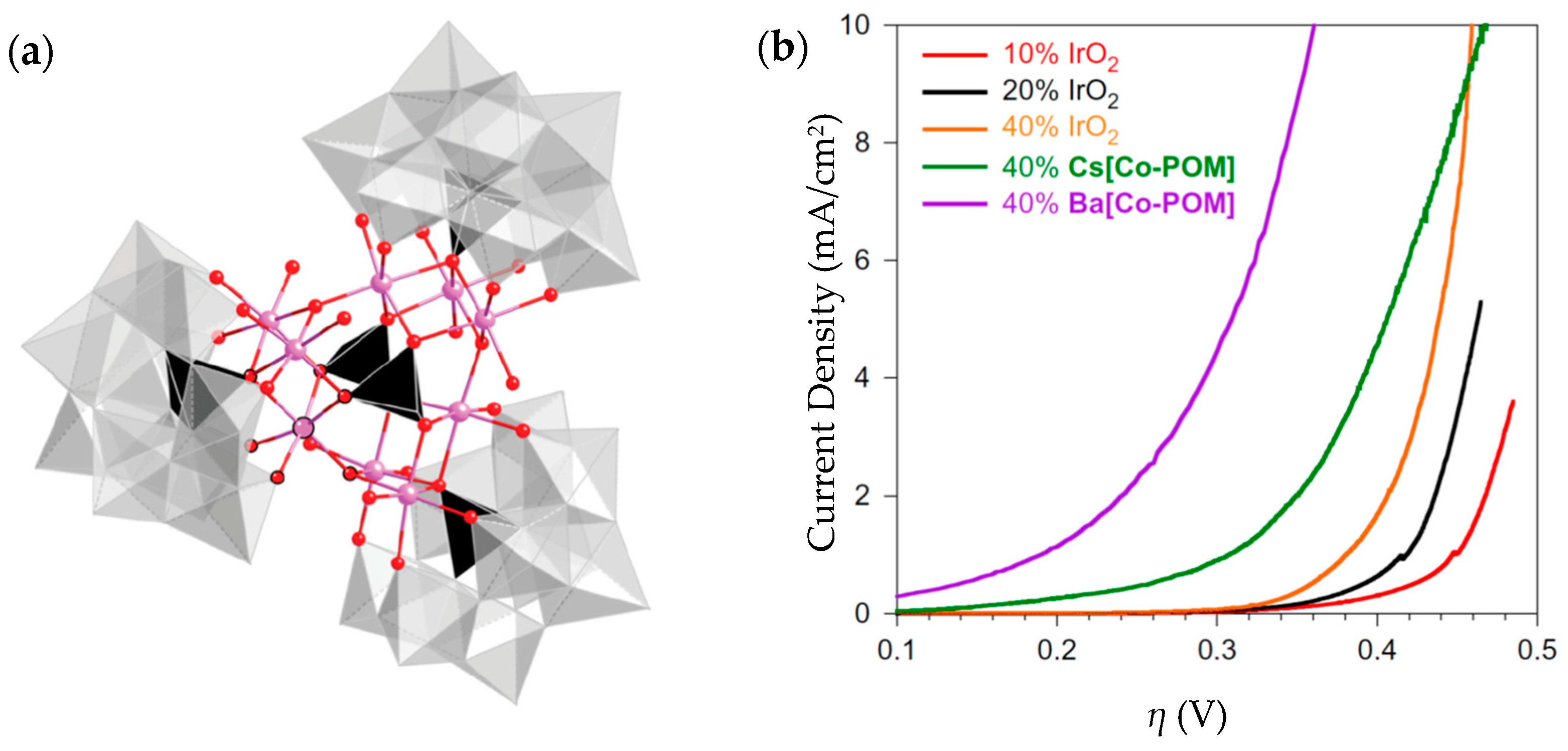
- Blasco-Ahicart, M.; Soriano-López, J.; Carbó, J.J.; Poblet, J.M.; Galan-Mascaros, J.R. Polyoxometalate electrocatalysts based on earth-abundant metals for efficient water oxidation in acidic media. Nat. Chem. 2017, 10, 24–30. [Google Scholar] [CrossRef] [PubMed]
- Rodríguez-García, B.; Reyes-Carmona, Á.; Jiménez-Morales, I.; Blasco-Ahicart, M.; Cavaliere, S.; Dupont, M.; Jones, D.; Rozière, J.; Galán-Mascarós, J.R.; Jaouen, F. Cobalt hexacyanoferrate supported on Sb-doped SnO2 as a non-noble catalyst for oxygen evolution in acidic medium. Sustain. Energy Fuels 2018, 2, 589–597. [Google Scholar] [CrossRef]
- Zhao, L.; Cao, Q.; Wang, A.; Duan, J.; Zhou, W.; Sang, Y.; Liu, H. Iron oxide embedded titania nanowires—An active and stable electrocatalyst for oxygen evolution in acidic media. Nano Energy 2018, 45, 118–126. [Google Scholar] [CrossRef]
- Kwong, W.L.; Lee, C.C.; Shchukarev, A.; Björn, E.; Messinger, J. High-performance iron (III) oxide electrocatalyst for water oxidation in strongly acidic media. J. Catal. 2018, 365, 29–35. [Google Scholar] [CrossRef]
- Yang, L.J.; Deng, Y.Q.; Zhang, X.F.; Liu, H.; Zhou, W.J. MoSe2 nanosheet/MoO2 nanobelt/carbon nanotube membrane as flexible and multifunctional electrodes for FULL water splitting in acidic electrolyte. Nanoscale 2018, 10, 9268–9275. [Google Scholar] [CrossRef] [PubMed]
- Han, N.; Yang, K.R.; Lu, Z.; Li, Y.; Xu, W.; Gao, T.; Cai, Z.; Zhang, Y.; Batista, V.S.; Liu, W.; et al. Nitrogen-doped tungsten carbide nanoarray as an efficient bifunctional electrocatalyst for water splitting in acid. Nat. Commun. 2018, 9, 924. [Google Scholar] [CrossRef] [PubMed]
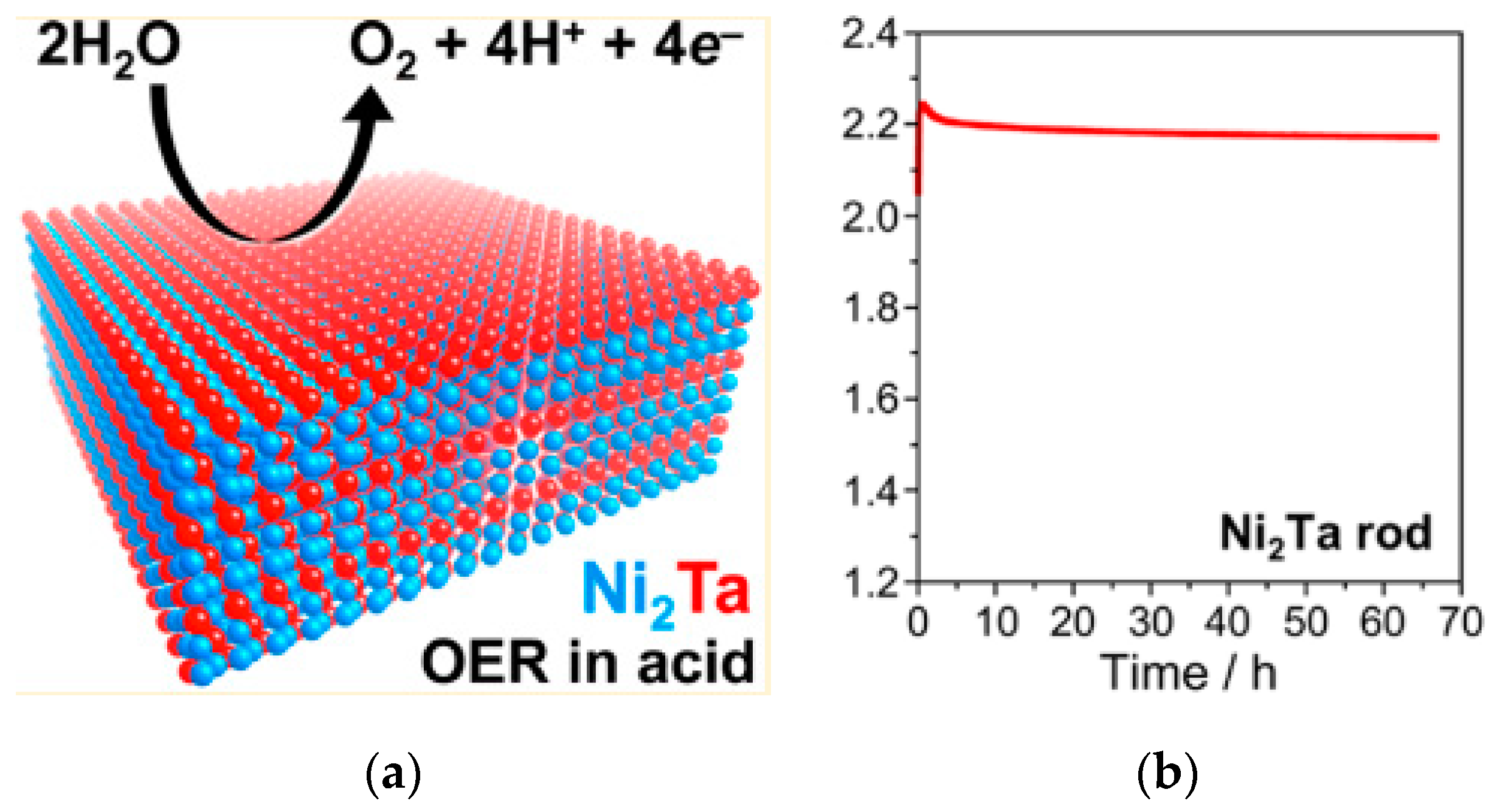
- Mondschein, J.S.; Kumar, K.; Holder, C.F.; Seth, K.; Kim, H.; Schaak, R.E. Intermetallic Ni2Ta Electrocatalyst for the Oxygen Evolution Reaction in Highly Acidic Electrolytes. Inorg. Chem. 2018, 57, 6010–6015. [Google Scholar] [CrossRef] [PubMed]
- Kolosov, V.N.; Matychenko, E.S.; Belyaevskii, A.T. The Corrosion Protection of Nickel Equipment in Chloride-Fluotantalate Melts. Prot. Met. 2000, 36, 545–550. [Google Scholar] [CrossRef]
- Lee, H.J.; Akiyama, E.; Habazaki, H.; Kawashima, A.; Asami, K.; Hashimoto, K. The corrosion behavior of amorphous and crystalline Ni-10Ta-20P alloys in 12 M HCl. Corros. Sci. 1996, 38, 1269–1279. [Google Scholar] [CrossRef]
- Schäfer, H.; Küpper, K.; Schmidt, M.; Müller-Buschbaum, K.; Stangl, J.; Daum, D.; Steinhart, M.; Schulz-Kölbel, C.; Han, W.; Wollschläger, J.; et al. Steel-based electrocatalysts for efficient and durable oxygen evolution in acidic media. Catal. Sci. Technol. 2018, 8, 2104–2116. [Google Scholar] [CrossRef] [Green Version]
- Spöri, C.; Kwan, J.T.H.; Bonakdarpour, A.; Wilkinson, D.P.; Strasser, P. The Stability Challenges of Oxygen Evolving Catalysts: Towards a Common Fundamental Understanding and Mitigation of Catalyst Degradation. Angew. Chem. Int. Ed. 2016, 56, 5994–6021. [Google Scholar] [CrossRef] [PubMed]


| Advantages [17,54,58] | Disadvantages [58,59,60] |
|---|---|
Compact system design
Solid, thin electrolyte
Operates at higher current density
| Acidic electrolyte
Solid, thin electrolyte
|
| Cathode | Anode | T | Test Cell | Current Density | Cell Voltage | Ref. |
|---|---|---|---|---|---|---|
| Pt/C 0.5 mgPt/cm2 | Ir0.5Ru0.3O2 2.5 mgoxide/cm2 | 25 °C | 5 cm2 PEM cell, Nafion 115 | 1 A/cm2 | ~2.2 V | [86] |
| Pt/C 0.5 mgPt/cm2 | Ir0.7Ru0.5O2 2.5 mgoxide/cm2 | ~2.3 V | ||||
| Pt/C 0.5 mgPt/cm2 | Ir0.7Ru0.5O2 1.5 mgoxide/cm2 | 90 °C | 5 cm2 PEM cell, Nafion 115 | 2.6 A/cm2 | 1.8 V | [73] |
| Pt/C 0.4 mgPt/cm2 | Ir0.7Ru0.3O2 thermally treated 1.0 mgoxide/cm2 | 80 °C | 25 cm2 PEM cell, Nafion 212 CS | 1 A/cm2 | ~1.7 V | [87] |
| Pt/C 0.1 mgPt/cm2 | Ir0.7Ru0.3O2 1.5 mgoxide/cm2 | 90 °C | 5 cm2 PEM cell, Aquivion ionomer | 1.3 A/cm2 | 1.6 V | [88] |
| Pt/C 0.4 mgPt/cm2 | Ir0.6Ru0.4O2 2.5 mgoxide/cm2 | 80 °C | 5 cm2 PEM cell, Nafion 115 | 1 A/cm2 | 1.567 V | [79] |
| Pt/C 0.4 mgPt/cm2 | Ir0.4Ru0.6O2 1.5 mgoxide/cm2 | 80 °C | 5 cm2 PEM cell, Nafion 115 | 1 A/cm2 | 1.676 V | [77] |
| Pt/C 0.5 mgPt/cm2 | Ir0.2Ru0.8O2 1.5 mgoxide/cm2 | 80 °C | 5 cm2 PEM cell, Nafion® 1035 | 1 A/cm2 | 1.622 V | [74] |
| Cathode (Loading in mg/cm2) | Membrane | Anode (Loading in mg/cm2) | Temp. (°C) | Performance | Stability | Ref. |
|---|---|---|---|---|---|---|
| MoS2 | Nafion 117 | IrO2 (2) | 80 °C | 0.02 A/cm2@1.9 V | Not reported | [84] |
| 47wt.% MoS2/CB (2.5) | Nafion 117 | IrO2 (2) | 80 °C | 0.3 A/cm2@1.9 V | Increasing current density after 18 h | [84] |
| MoS2/rGO (3) | Nafion 117 | IrO2 (2) | 80 °C | 0.1 A/cm2@1.9 V | Not reported | [84] |
| MoSx/CB (3) | Nafion 115 | Ir black(2) | 80 °C | 0.9 A/cm2@2.0 V | Stable current density over 24 h | [105] |
| Mo3S13/CB (3) | Nafion 115 | Ir black(2) | 80 °C | 1.1 A/cm2@2.0 V | Current density decreased by more than 100 mA/cm2 after 24 h | [105] |
| MoS2 nCapsules (2) | Nafion 117 | IrO2 (2) | 80 °C | 0.06 A/cm2@2.0 V | Stable current density for 200 h | [106] |
| MoSx/C-cloth | Nafion 117 | RuO2 (2) | 80 °C | 0.3 A/cm2@2.0 V | Not reported | [107] |
| MoSx/C-paper | Nafion 212 | IrO2 (0.1) | 90 °C | 0.37 A/cm2@1.9 V | Stable current density over 4 h | [108] |
| Pyrite FeS2 | Nafion 115 | IrO2 (2) | 80 °C | 1 A/cm2@2.101 V | Stable for 100 h | [145] |
| Greigite Fe3S4 | Nafion 115 | IrO2 (2) | 80 °C | 1 A/cm2@2.130 V | Stable for 100 h | [145] |
| Pyrrholite Fe9S10 | Nafion 115 | IrO2 (2) | 80 °C | 1 A/cm2@2.158 V | Stable for 100 h | [145] |
| 30 wt.% Pd/P-doped C (carbon black) | Nafion 115 | RuO2 (3) | 80 °C | 1 A/cm2@2 V | Stable for 500 h | [171] |
| 30 wt.% Pd/N-doped CNTs | Nafion 115 | RuO2 (3) | 80 °C | 1 A/cm2@2.01 V | Stable for 50 h | [172] |
| 30 wt.% Pd/P-doped Graphene | Nafion 115 | RuO2 (3) | 80 °C | 1 A/cm2@1.95 V | Cell voltage increased to 2.0 V after 2000 h | [173] |
| Activated single-wall carbon nanotubes | Nafion 115 | IrRuOx | 80 °C | 1 A/cm2@1.64 V | Stable for 90 h | [174] |
| Co NPs/N-doped C | Nafion NRE-212 | IrO2 (0.55) | 80 °C | 1 A/cm2@150 mV η from Pt/C | Not tested in the full cell. Stable cathode after 10,000 CV cycles @ 100 mV/s | [175] |
| Boron-capped tris (glyoximato) cobalt complexes on carbon black (Co(dmg)/C) 1 mg/cm2 | Nafion 117 | Ir black (2–2.5) | 90 °C | 1 A/cm2@2.1 V | Not reported | [62] |
| [Co(dmgBF2)2]-Vulcan XC72 2.5 mg/cm2 * | Nafion 117 | IrO2 | 60 °C | 0.5A/cm2@1.7 V | No sign of degradation after 60 h @ 0.2 A/cm2 | [165] |
| [Co(dmg)3(BF)2]BF4-Vulcan XC72 2.5 mg/cm2 * | Nafion 117 | IrO2 | 60 °C | 0.65A/cm2@1.7 V | [165] | |
| Co hexachloroclathrochelates impregnated on Vulcan XC72 5–12 × 10−4 mg/cm2 ** | Nafion 117 | Ir black | 80 °C | 1 A/cm2@2.15 V | Not reported | [166] |
| Material | η mV | Tafel mV/Decade | Loading | Media | Stability | OER Faradaic Efficiency | Applied in Full PEM WE Cell | Ref. |
|---|---|---|---|---|---|---|---|---|
| Activated MnOx | [email protected] mA/cm2 | 90 | thin film 2–4 nm | 0.5 M H2SO4, pH = 2.5 | 8 [email protected] mA/cm2 | ~1% | - | [197] |
| CoMnOx | [email protected] mA/cm2 | 70–80 | films | 0.5 M H2SO4, pH = 2.5 | 12 [email protected] mA/cm2 | 91% average | - | [198] |
| Ti-stabilized MnO2 | ~490@1 mA/cm2 | 170 | thin film 40 nm | 0.05 M H2SO4 | 89%, [email protected] | - | - | [199] |
| Cu1.5Mn1.5O4:10F | [email protected] mA/cm2 | 60 | 1 mg/cm2 | 0.5 M H2SO4 | 24 h@16 mA/cm2 | - | ORR in PEM fuel cell | [200] |
| MEMD | 305@100 mA/cm2 | 115 | roughness factor 429/for DSA 388 | 2 M H2SO4 | 3500 s@280 mV | - | - | [201] |
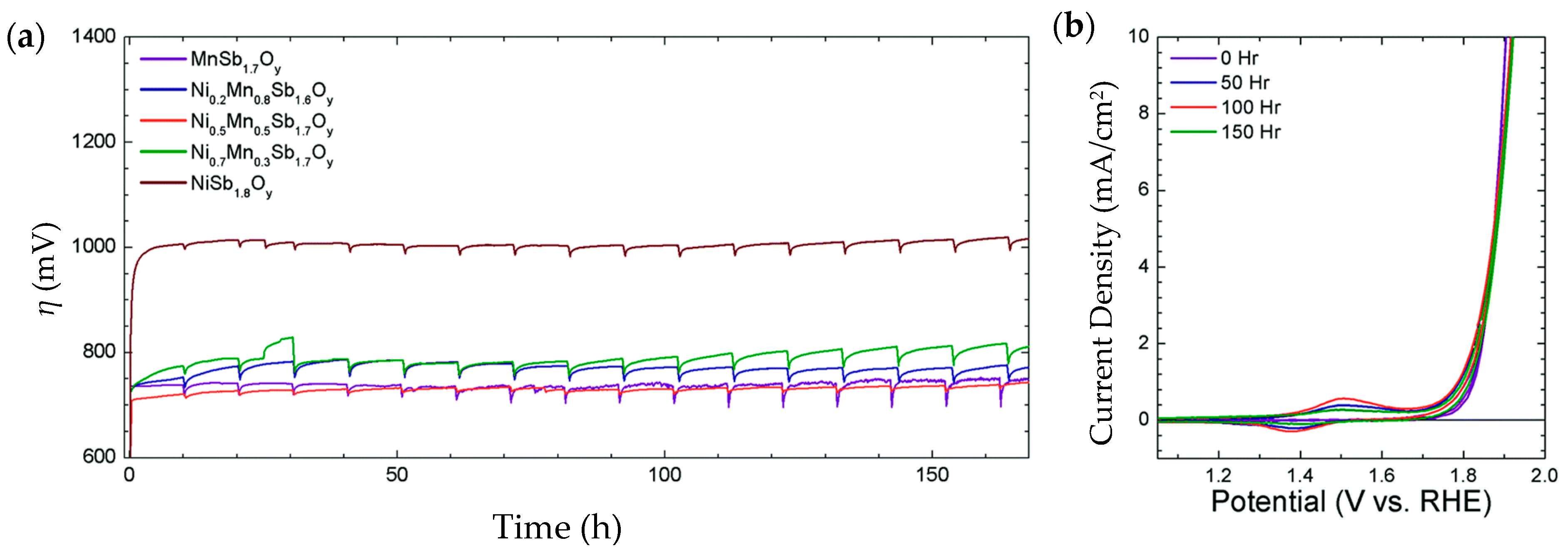
| Ni0.5Mn0.5Sb1.7Oy | 675@10 mA/cm2 | 60 | thin film ~300 nm. Ni content 0.48 μmol/cm2 | 1 M H2SO4 | 168 h@10 mA/cm2. η increased to 735 mV | 95% average | - | [202] |
| crystalline Co3O4 | 570@10 mA/cm2 | 80 | thin film ~300 nm. | 0.5 M H2SO4, pH = 0.3 | 12 h@10 mA/cm2. Dissolution rate 100 ng/min | above 95% | - | [209] |
| Ag-doped Co3O4 | 680@10 mA/cm2 | 219 | film, 32.81 m2/g | 0.5 M H2SO4 | 10 h@6 mA/cm2 | - | - | [210] |
| PB-type | 830@10 mA/cm2 | 108 | film on FTO. | 0.1 M KPi buffer, pH = 2 | 2 h@10 mA/cm2 | close to [email protected] mA/cm2 | - | [211] |
| Ba[Co-POM] | 189@1 mA/cm2 | 66 | 11 mg | 1 M H2SO4, pH = 0.2 | From >2 mA/cm2 to 0.35 after 24 h | 99% | - | [212] |
| CoHFe on Sb-doped SnO2 | [email protected] mA/cm2 | - | 0.61 mg/cm2 | 0.1 M H2SO4, | - | - | OER. 50-100 mA@2 V. 6 mA/cm2@1.8 V with 0.5 mg cm-2. Stability: 21 h. Cathode: 0.5 mg/cm2 Pt/C | [213] |
| Fe-TiOx LNWs/Ti | 260@1 mA/cm2 | 126.2 | 60 mg/cm2 as of Fe2O3 | 0.5 M H2SO4 | 20 [email protected] V. 18.7% current reduction | - | - | [214] |
| Mixed maghemite-hematite | 650@10 mA/cm2 | 56 | 1 mg/cm2 | 0.5 M H2SO4, pH = 0.3 | >24 h@10 mA/cm2. | ~100% | - | [215] |
| MoSe2 nanosheet/MnO2 nanobelt/CNT (bifunctional) | 400@10 mA/cm2 | 112.3 | 98.46 m2/g | 0.5 M H2SO4 | 10 [email protected] mA/cm2 | - | Two-electrode electrolyzer as anode and cathode@2 V | [216] |
| N-doped WC nanoarray (bifunctional) | 470@60 mA/cm2 | - | 10 mg/cm2 | 0.5 M H2SO4 | 1 h@10 mA/cm2, η increases from 120 to 310 mV | - | Two-electrode electrolyzer as anode and [email protected] V | [217] |
| Intermetallic polycrystalline Ni2Ta | 570@10 mA/cm2 | - | 0.84 cm2 as EASA | 0.5 M H2SO4 | >66 h@10 mA/cm2. | 85%@20 mA/cm2 | - | [218] |
| Ni42Li205 steel | 445@10 mA/cm2 | 150 | 0.05 M H2SO4 pH = 2 | 20 μg/mm2 loss after 14 h@10mA/cm2 | 79%@20 mA/cm2 | - | [221] |
| Cathode | Anode | T | Membrane | Current Density | Ref. |
|---|---|---|---|---|---|
| Pt/C 0.1 mgPt/cm2 | Ir0.7Ru0.3O2 1.5 mgoxide/cm2 | 90 °C | Aquivion ionomer | 1.3 A/cm2@1.6 V | [88] |
| Pt/C 0.5 mgPt/cm2 | Ir0.7Ru0.5O2 1.5 mgoxide/cm2 | 90 °C | Nafion 115 | 2.6 A/cm2@1.8 V | [73] |
| Activated single-wall carbon nanotubes (SWNTs) | IrRuOx | 80 °C | Nafion 115 | 1 A/cm2@1.64 V | [174] |
| Mo3S13/CB 3 mgPt/cm2 | Ir black(2) | 80 °C | Nafion 115 | 1.1 A/cm2@2.0 V | [105] |
| Pt/C 0.5 mg/cm2 | CoHFe on Sb-doped SnO2 3 mg/cm2 | 80 °C | Nafion 115 | 0.05-0.1 A/cm2@2 V | [213] |
© 2018 by the authors. Licensee MDPI, Basel, Switzerland. This article is an open access article distributed under the terms and conditions of the Creative Commons Attribution (CC BY) license (http://creativecommons.org/licenses/by/4.0/).
Share and Cite
Sun, X.; Xu, K.; Fleischer, C.; Liu, X.; Grandcolas, M.; Strandbakke, R.; Bjørheim, T.S.; Norby, T.; Chatzitakis, A. Earth-Abundant Electrocatalysts in Proton Exchange Membrane Electrolyzers. Catalysts 2018, 8, 657. https://0-doi-org.brum.beds.ac.uk/10.3390/catal8120657
Sun X, Xu K, Fleischer C, Liu X, Grandcolas M, Strandbakke R, Bjørheim TS, Norby T, Chatzitakis A. Earth-Abundant Electrocatalysts in Proton Exchange Membrane Electrolyzers. Catalysts. 2018; 8(12):657. https://0-doi-org.brum.beds.ac.uk/10.3390/catal8120657
Chicago/Turabian StyleSun, Xinwei, Kaiqi Xu, Christian Fleischer, Xin Liu, Mathieu Grandcolas, Ragnar Strandbakke, Tor S. Bjørheim, Truls Norby, and Athanasios Chatzitakis. 2018. "Earth-Abundant Electrocatalysts in Proton Exchange Membrane Electrolyzers" Catalysts 8, no. 12: 657. https://0-doi-org.brum.beds.ac.uk/10.3390/catal8120657