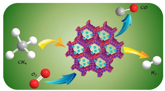
The Role of Active Sites Location in Partial Oxidation of Methane to Syngas for MCM-41 Supported Ni Nanoparticles

Abstract
:
1. Introduction
2. Results and Discussion
2.1. Characterization before Tests
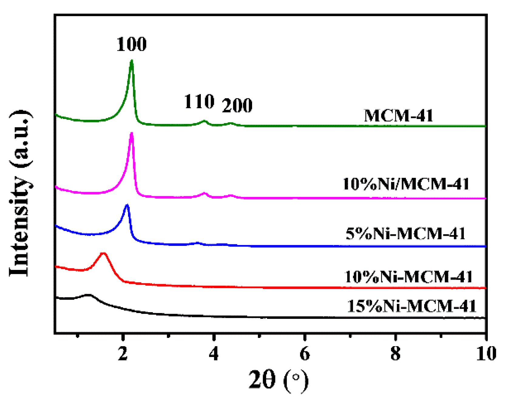
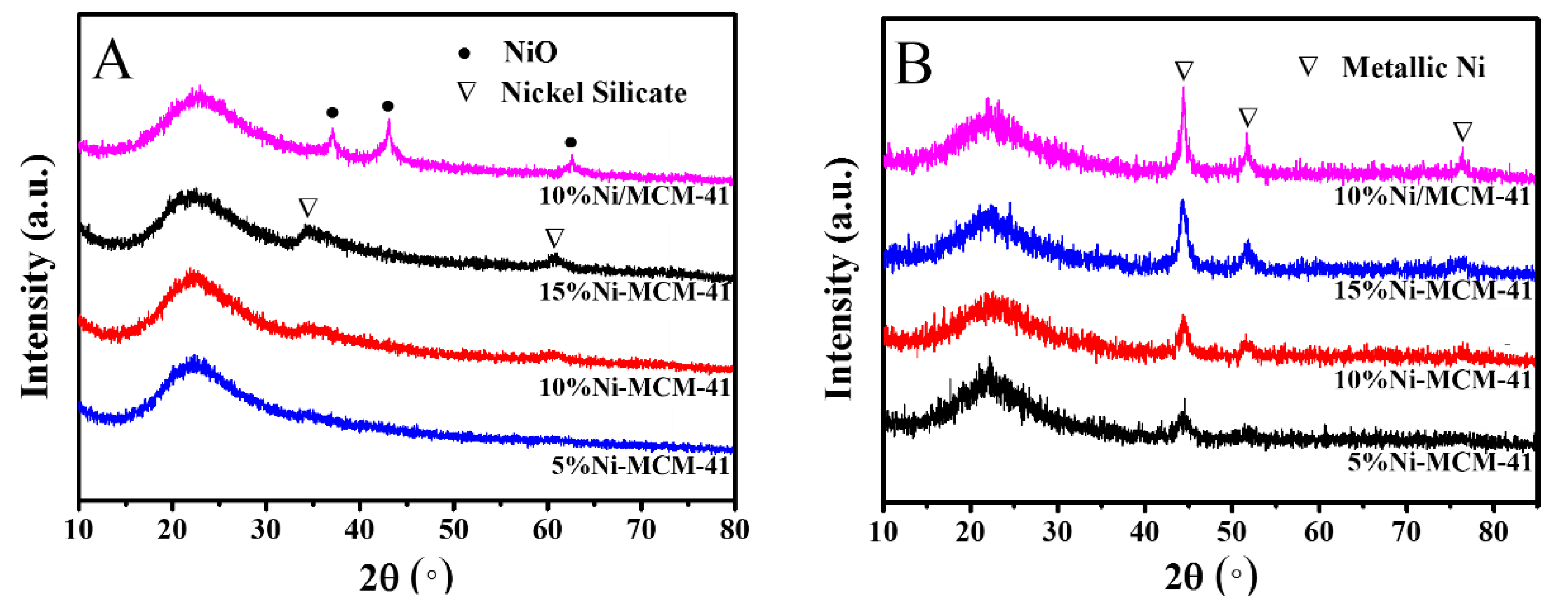
2.1.1. Phase Composition
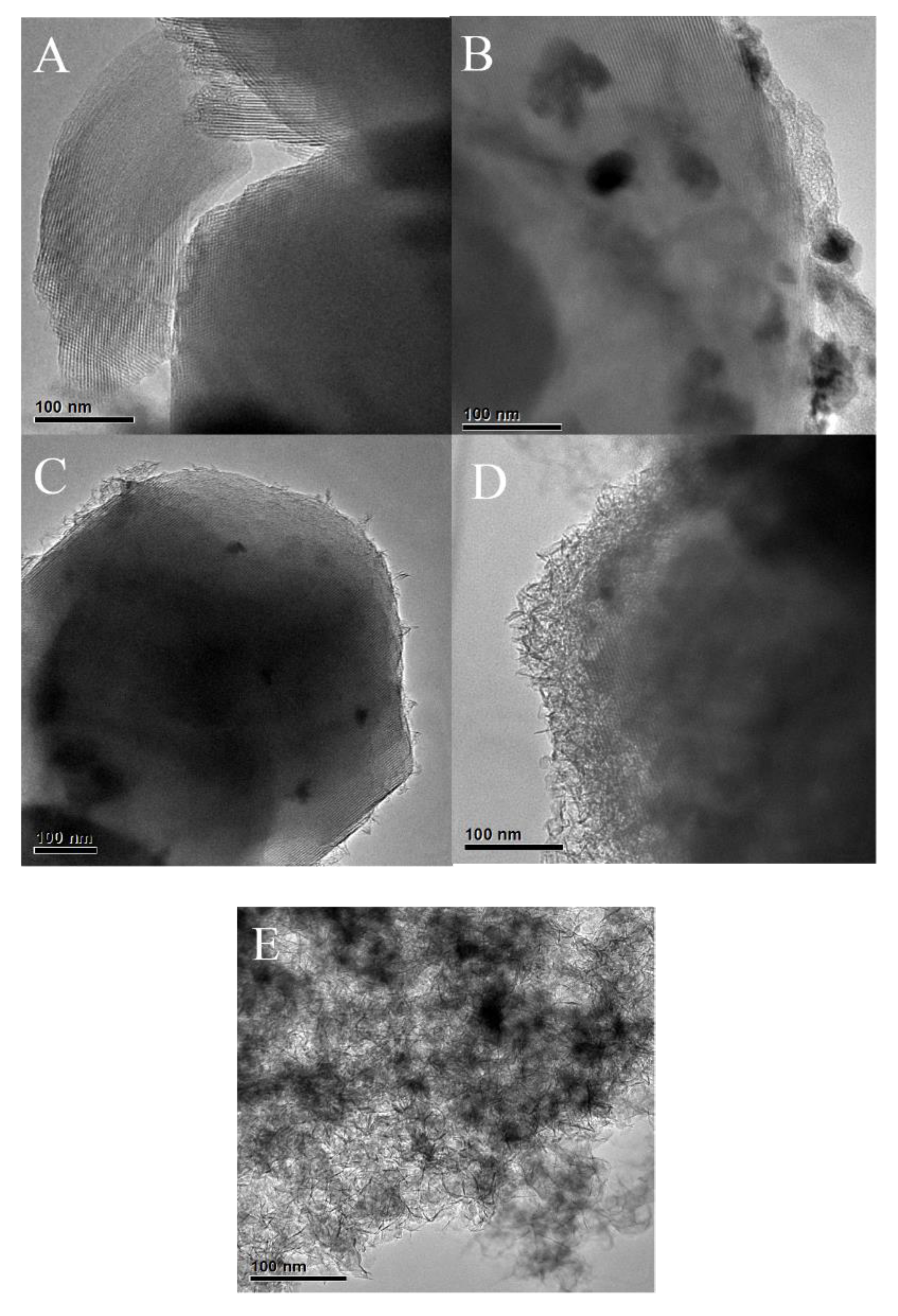
2.1.2. TEM
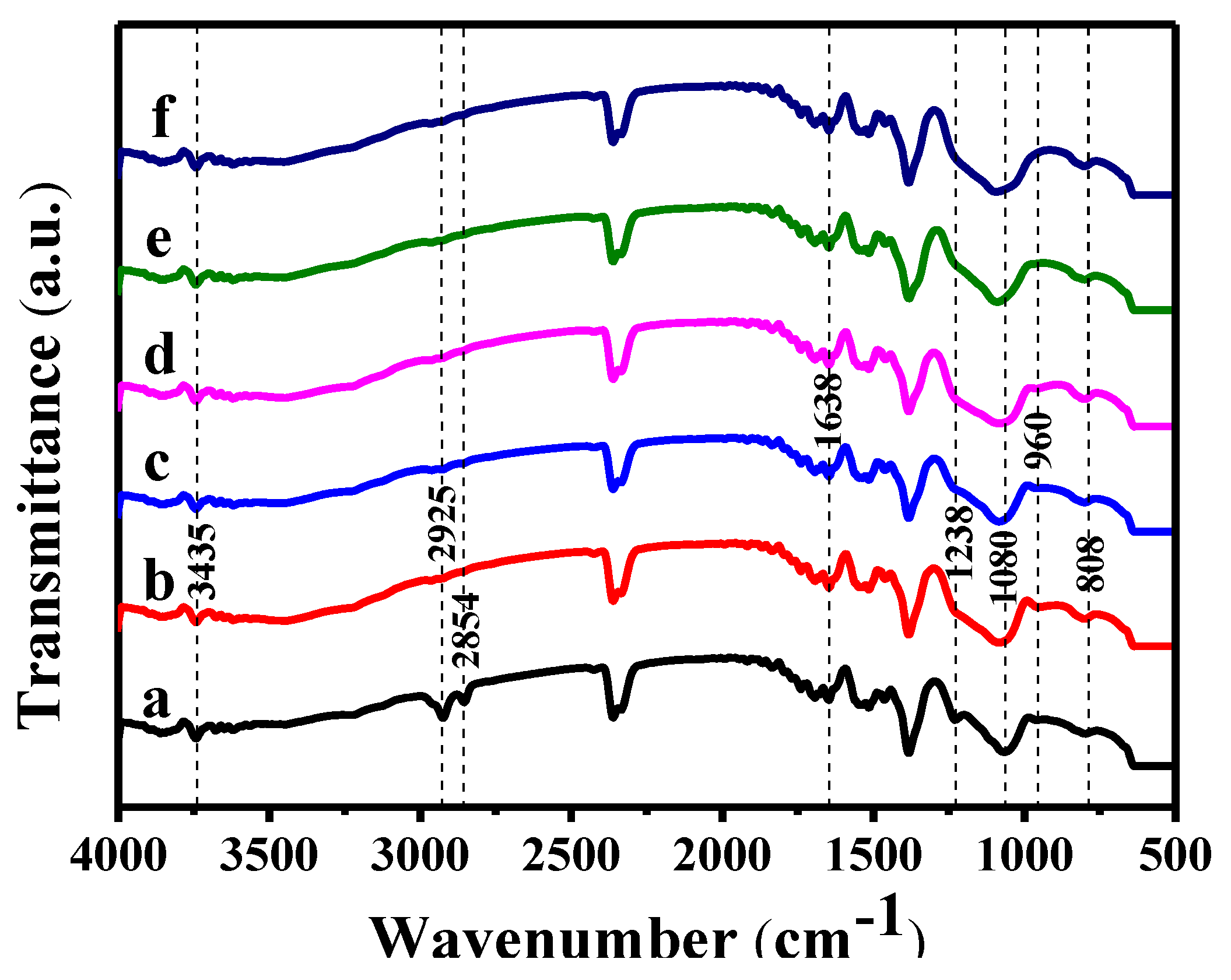
2.1.3. FT-IR
2.1.4. Location Determination of Ni by ICP
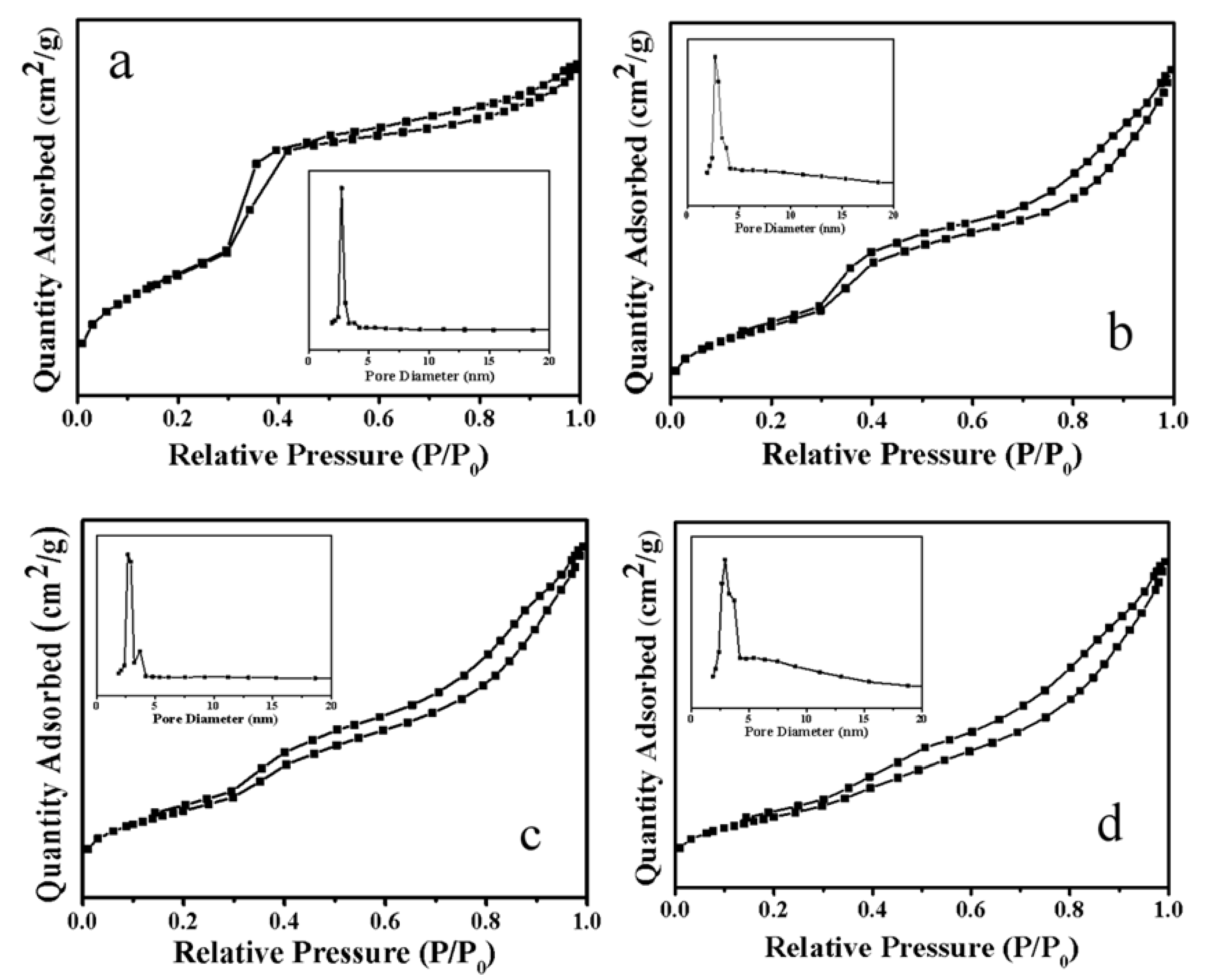
2.1.5. N2 Adsorption-Desorption
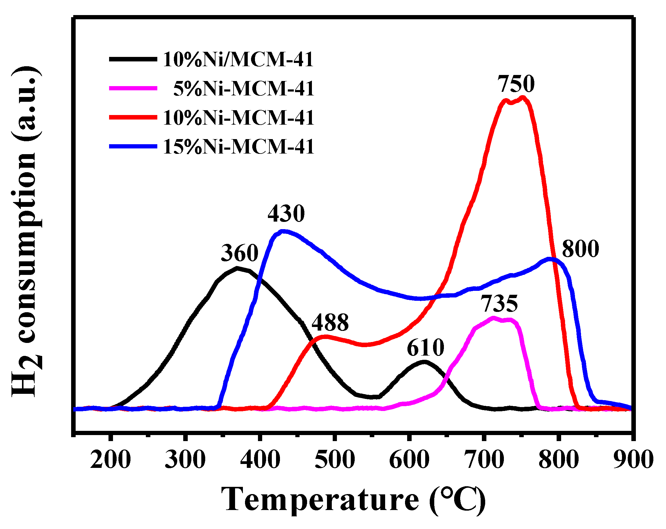
2.1.6. H2-TPR
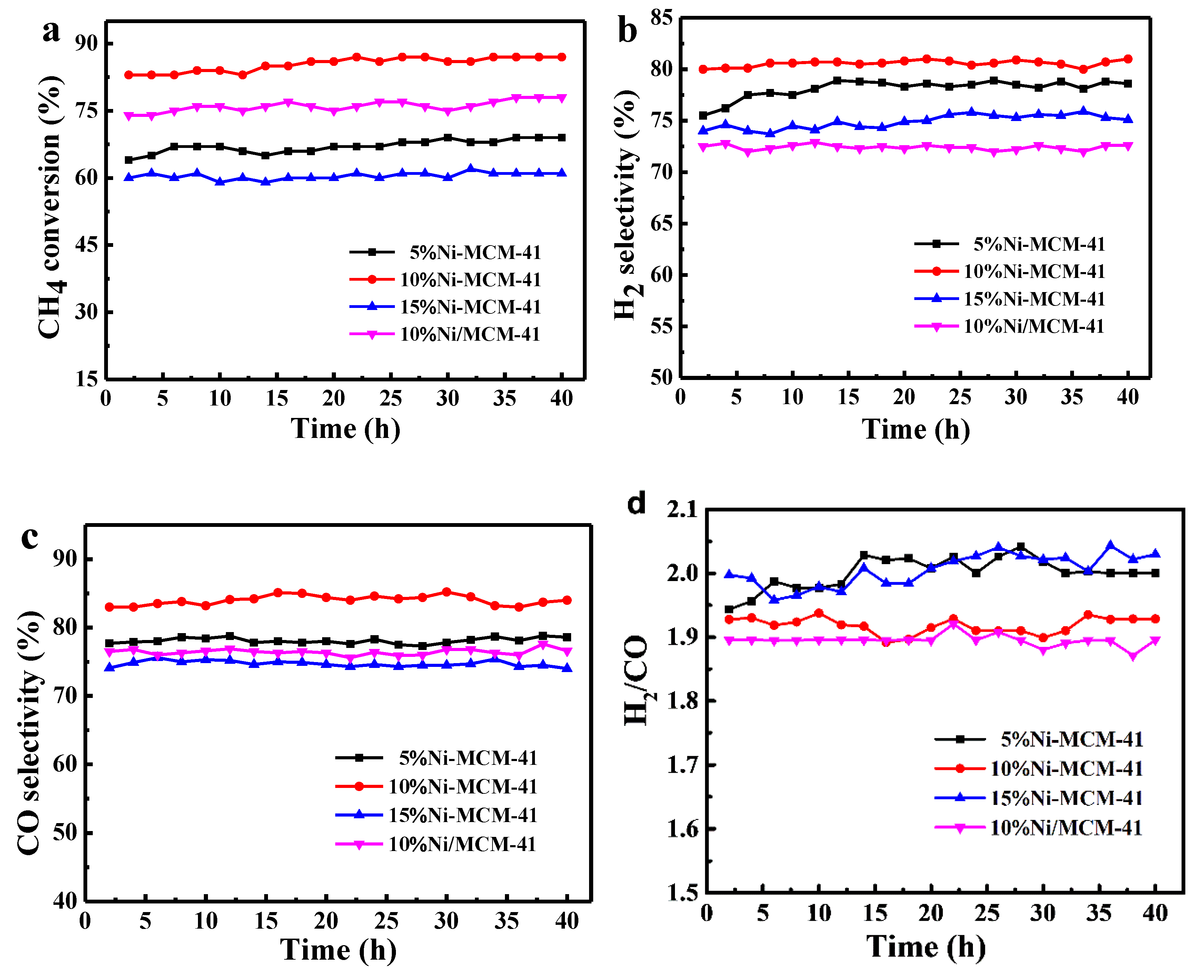
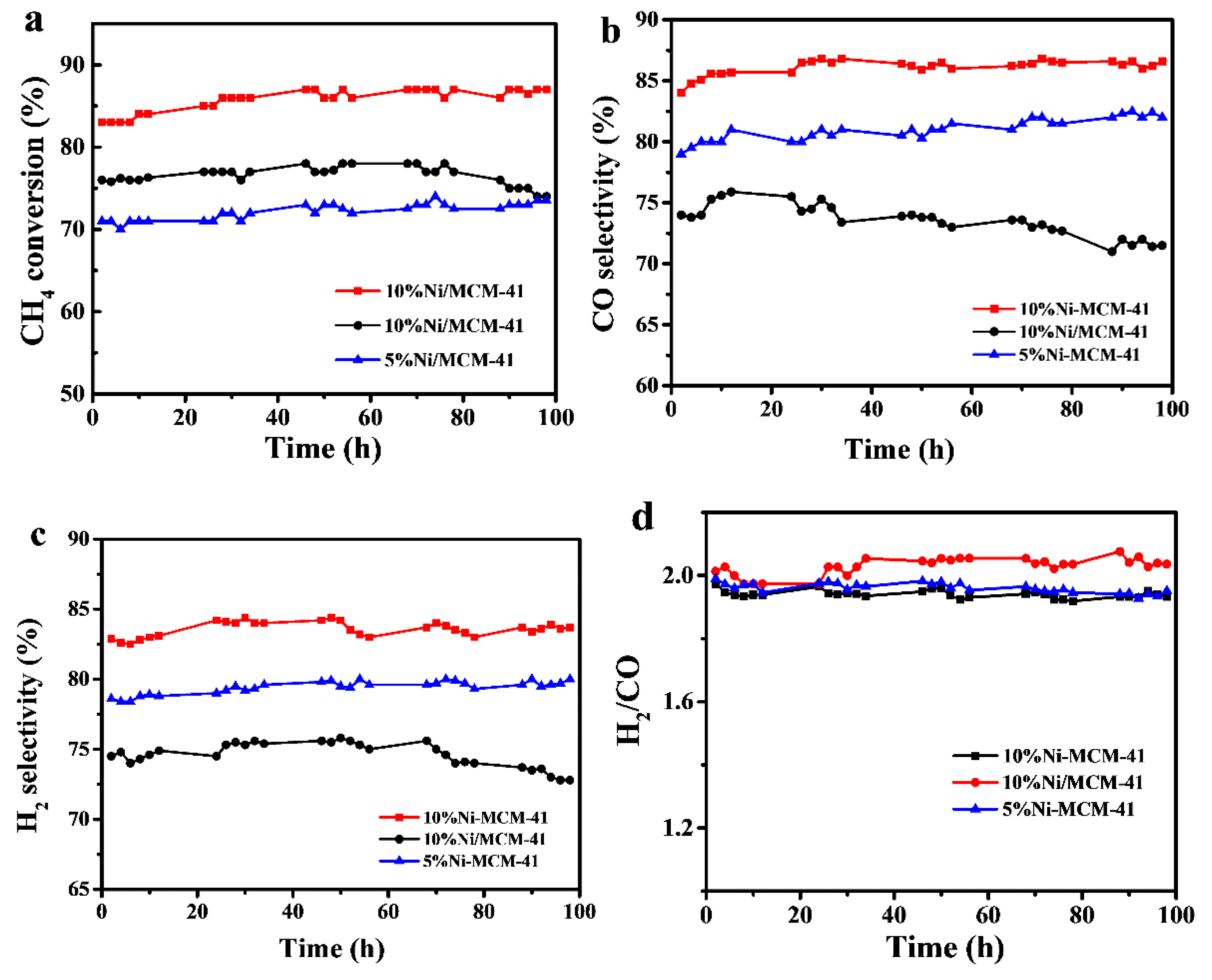
2.2. POM Catalytic Activity and Stability
2.2.1. Comparison of Catalytic Performance between Ni/MCM-41 and Ni-MCM-41
2.2.2. Catalytic Stability
2.3. Characterization after Tests
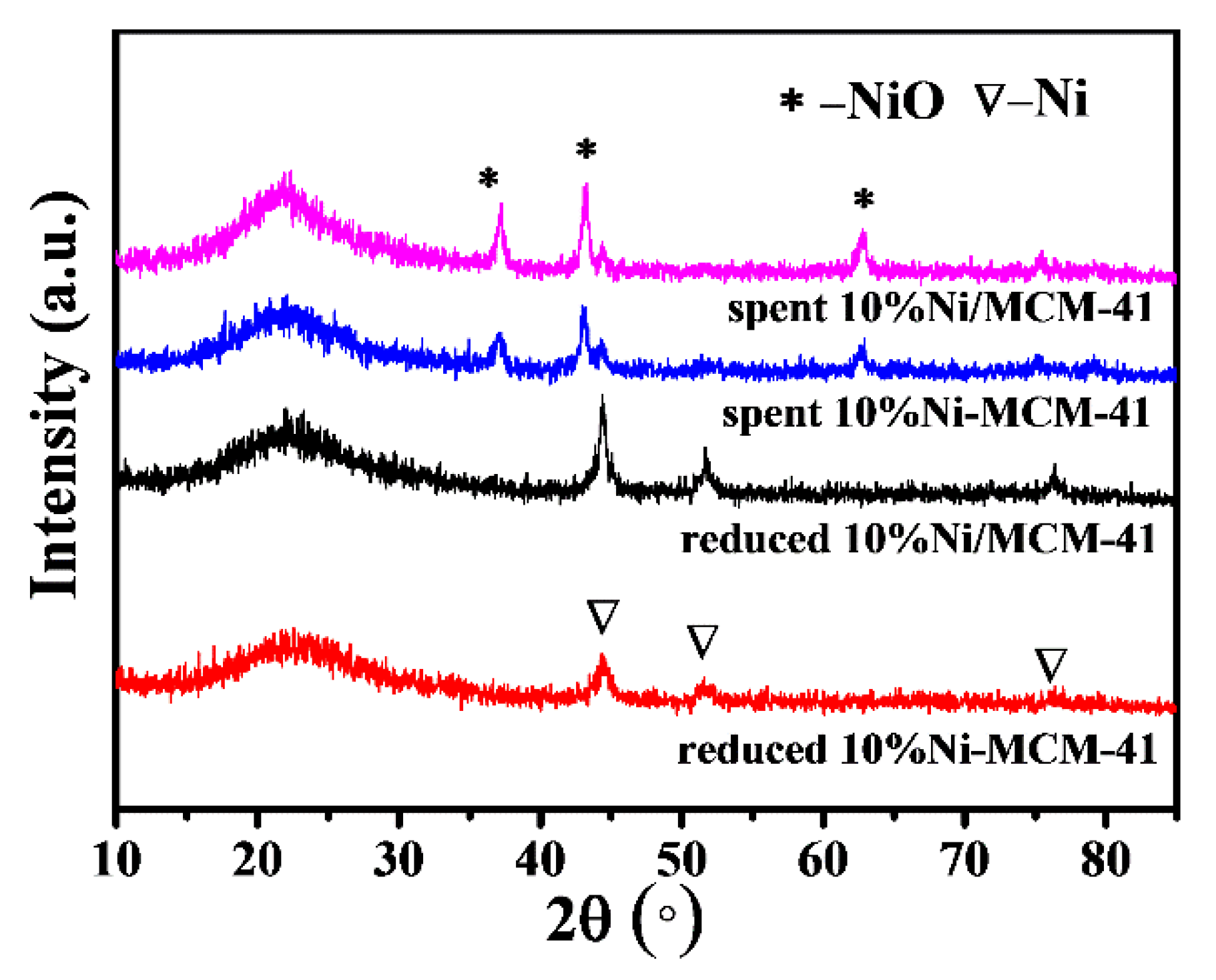
2.3.1. Phase Composition
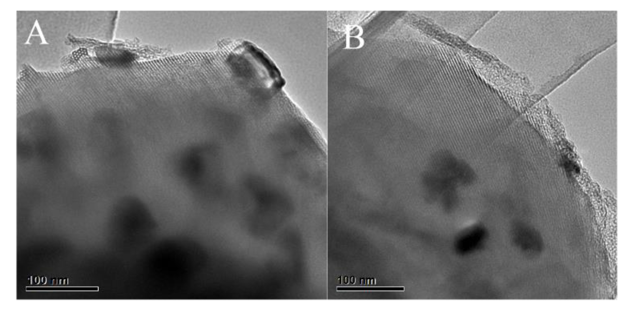
2.3.2. TEM
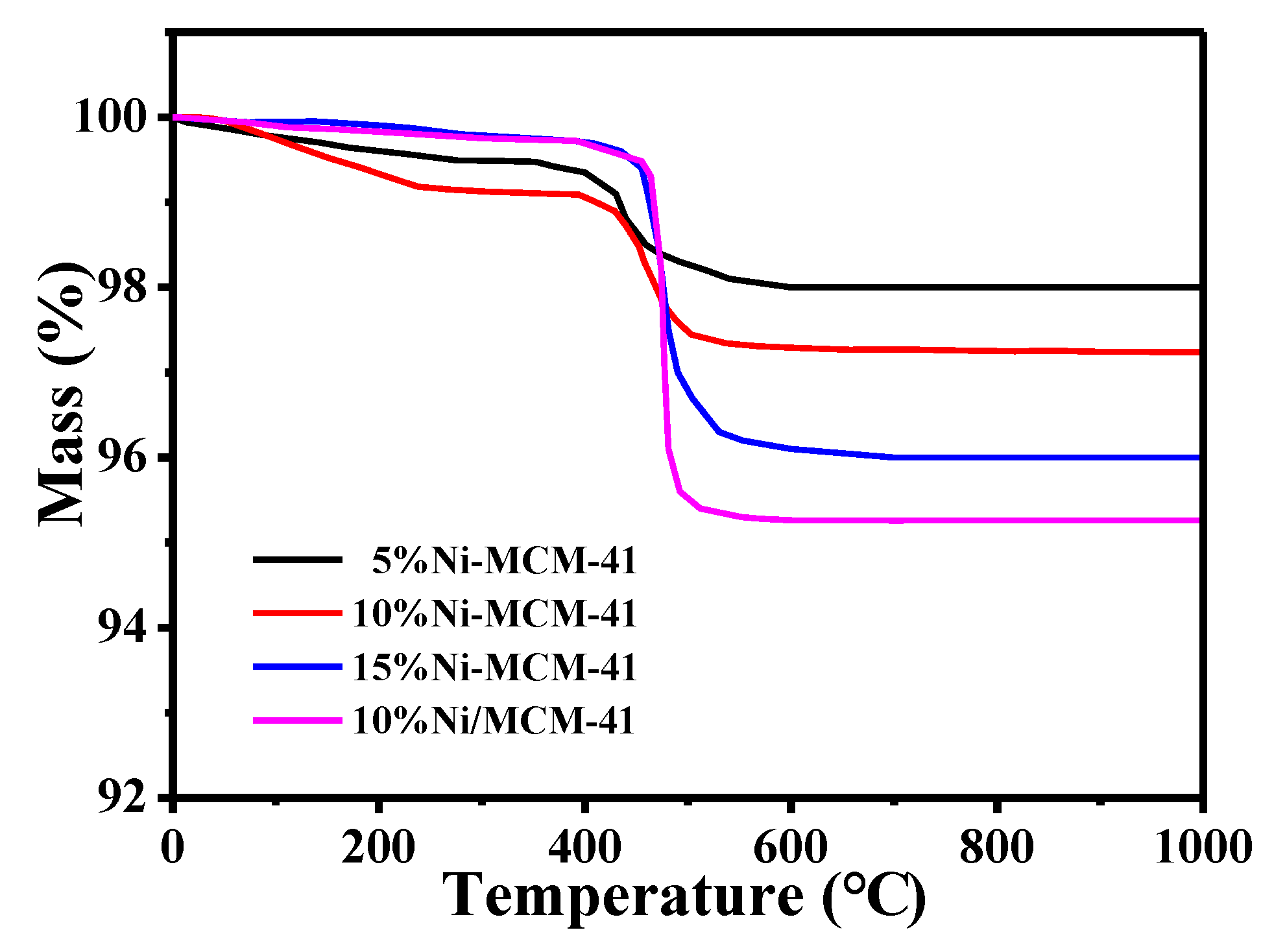
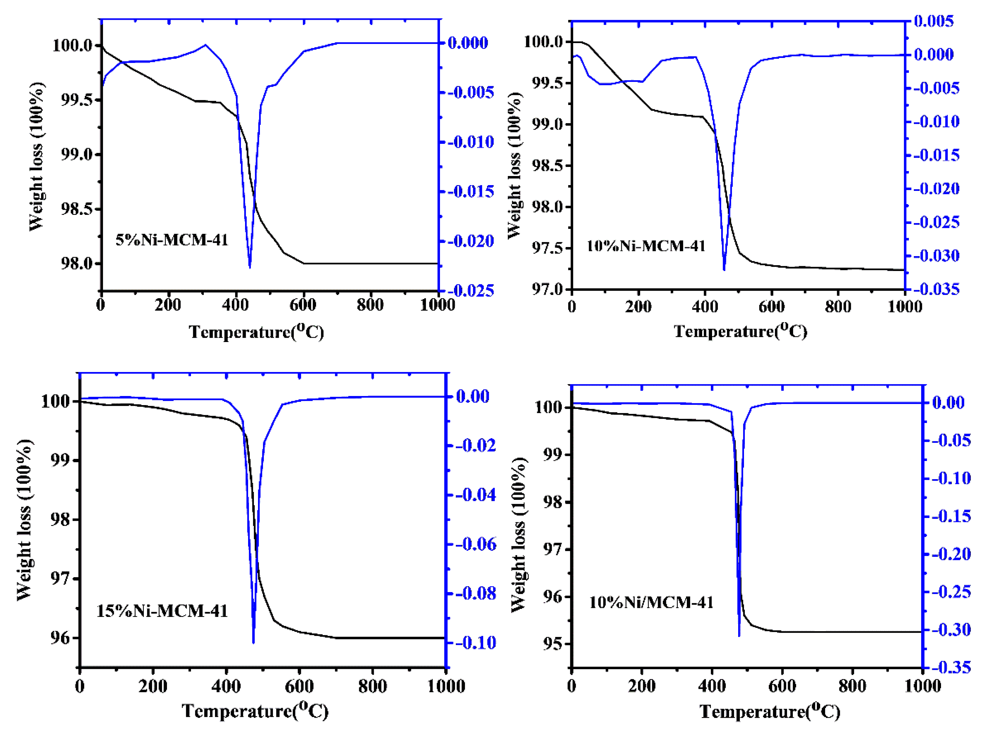
2.3.3. TGA
3. Experimental
3.1. Materials
3.2. Preparation of Catalysts
3.3. Catalyst Characterization
3.4. Catalyst Evaluation
4. Conclusions
Author Contributions
Funding
Acknowledgments
Conflicts of Interest
References
- Sattler, J.J.H.B.; Gonzalez-Jimenez, I.D.; Luo, L.; Stears, B.A.; Malek, A.; Barton, D.G.; Kilos, B.A.; Kaminsky, M.P.; Verhoeven, T.W.G.M.; Koers, E.J.; et al. Platinum-Promoted Ga/Al2O3as Highly Active, Selective, and Stable Catalyst for the Dehydrogenation of Propane. Angew. Chem. 2014, 126, 9405–9410. [Google Scholar] [CrossRef]
- Guo, C.; Zhang, X.; Zhang, J.; Wang, Y. Preparation of La2NiO4 catalyst and catalytic performance for partial oxidation of methane. J. Mol. Catal. A: Chem. 2007, 269, 254–259. [Google Scholar] [CrossRef]
- Bonura, G.; Migliori, M.; Frusteri, L.; Cannilla, C.; Catizzone, E.; Giordano, G.; Frusteri, F. Acidity control of zeolite functionality on activity and stability of hybridcatalysts during DME production via CO2 hydrogenation. J. CO2 Util. 2018, 24, 398–406. [Google Scholar] [CrossRef]
- Perathoner, S.; Centi, G. CO2Recycling: A Key Strategy to Introduce Green Energy in the Chemical Production Chain. ChemSusChem 2014, 7, 1274–1282. [Google Scholar] [CrossRef] [PubMed]
- Catizzone, E.; Cirelli, Z.; Aloise, A.; Lanzafame, P.; Migliori, M.; Giordano, G. Methanol conversion over ZSM-12, ZSM-22 and EU-1 zeolites: from DME to hydrocarbons production. Catal. Today 2018, 304, 39–50. [Google Scholar] [CrossRef]
- Horiguchi, J.; Kobayashi, Y.; Kobayashi, S.; Yamazaki, Y.; Omata, K.; Nagao, D.; Konno, M.; Yamada, M. Mesoporous NiO–Al2O3 catalyst for high pressure partial oxidation of methane to syngas. Appl. Catal. A: Gen. 2011, 392, 86–92. [Google Scholar] [CrossRef]
- Singha, R.K.; Shukla, A.; Yadav, A.; Konathala, L.N.S.; Bal, R. Effect of metal-support interaction on activity and stability of Ni-CeO2 catalyst for partial oxidation of methane. Appl. Catal. B-Environ. 2017, 202, 473–488. [Google Scholar] [CrossRef]
- Argyle, M.D.; Bartholomew, C.H. Heterogeneous catalyst deactivation and regeneration: A review. Catalysts 2015, 5, 145–269. [Google Scholar] [CrossRef]
- Ding, C.; Ai, G.; Zhang, K.; Yuan, Q.; Han, Y.; Ma, X.; Wang, J.; Liu, S. Coking resistant Ni/ZrO2@SiO2 catalyst for the partial oxidation of methane to synthesis gas. Int. J. Hydrog. Energy 2015, 40, 6835–6843. [Google Scholar] [CrossRef]
- Özdemir, H.; Öksüzömer, M.A.F.; Gürkaynak, M.A. Effect of the calcination temperature on Ni/MgAl2O4 catalyst structure and catalytic properties for partial oxidation of methane. Fuel 2014, 116, 63–70. [Google Scholar] [CrossRef]
- Vartuli, J.C.; Roth, W.J.; Degnan, T.F. Mesoporous Materials (M41S): From Discovery to Application. In Dekker Encyclopedia of Nanoscience and Nanotechnology; Marcel Dekker: New York, NY, USA, 2004; p. 1791. [Google Scholar]
- Gucbilmez, Y.; Doğu, T.; Balci, S. Ethylene and Acetaldehyde Production by Selective Oxidation of Ethanol Using Mesoporous V−MCM-41 Catalysts. Ind. Eng. Chem. Res. 2006, 45, 3496–3502. [Google Scholar] [CrossRef]
- Sener, C.; Doğu, T.; Dogu, G. Effects of synthesis conditions on the structure of Pd incorporated MCM-41 type mesoporous nanocomposite catalytic materials with high Pd/Si ratios. Microporous Mesoporous Mater. 2006, 94, 89–98. [Google Scholar] [CrossRef]
- Yasyerli, S.; Filizgok, S.; Arbag, H.; Yasyerli, N.; Dogu, G. Ru incorporated Ni–MCM-41 mesoporous catalysts for dry reforming of methane: Effects of Mg addition, feed composition and temperature. Int. J. Hydrog. Energy 2011, 36, 4863–4874. [Google Scholar] [CrossRef]
- Arbag, H.; Yaşyerli, S.; Yasyerli, N.; Dogu, G. Activity and stability enhancement of Ni-MCM-41 catalysts by Rh incorporation for hydrogen from dry reforming of methane. Int. J. Hydrog. Energy 2010, 35, 2296–2304. [Google Scholar] [CrossRef]
- Qin, J.; Li, B.; Zhang, W.; Lv, W.; Han, C.; Liu, J. Synthesis, characterization and catalytic performance of well-ordered mesoporous Ni-MCM-41 with high nickel content. Microporous Mesoporous Mater. 2015, 208, 181–187. [Google Scholar] [CrossRef]
- Liu, H.M.; Li, Y.M.; Wu, H.; Yang, W.W.; He, D.H. Promoting effect of glucose and b-cyclodextrin on Ni dispersion of Ni/MCM-41 catalysts for carbon dioxide reforming of methane to syngas. Fuel 2014, 136, 19–24. [Google Scholar] [CrossRef]
- Qiu, S.; Xu, Y.; Weng, Y.; Ma, L.; Wang, T. Efficient Hydrogenolysis of Guaiacol over Highly Dispersed Ni/MCM-41 Catalyst Combined with HZSM-5. Catalysts 2016, 6, 134. [Google Scholar] [CrossRef]
- Yang, Y.; Lim, S.; Du, G.; Chen, Y.; Ciuparu, D.; Haller, G.L. Synthesis and Characterization of Highly Ordered Ni-MCM-41 Mesoporous Molecular Sieves. J. Phys. Chem. B 2005, 109, 13237–13246. [Google Scholar] [CrossRef]
- Al-Fatesh, A.S.; Ibrahim, A.A.; Abu-Dahrieh, J.K.; Al-Awadi, A.S.; El-Toni, A.M.; Fakeeha, A.H.; Abasaeed, A.E. Gallium-Promoted Ni Catalyst Supported on MCM-41 for Dry Reforming of Methane. Catalysts 2018, 8, 229. [Google Scholar] [CrossRef]
- Du, G.; Lim, S.; Yang, Y.; Wang, C.; Pfefferle, L.; Haller, G.L. Methanation of carbon dioxide on Ni-incorporated MCM-41 catalysts: The influence of catalyst pretreatment and study of steady-state reaction. J. Catal. 2007, 249, 370–379. [Google Scholar] [CrossRef]
- Li, X.-K.; Ji, W.-J.; Zhao, J.; Wang, S.-J.; Au, C.T. Ammonia decomposition over Ru and Ni catalysts supported on fumed SiO2, MCM-41, and SBA-15. J. Catal. 2005, 236, 181–189. [Google Scholar] [CrossRef]
- Parvulescu, V.; Su, B.-L. Iron, cobalt or nickel substituted MCM-41 molecular sieves for oxidation of hydrocarbons. Catal. Today 2001, 69, 315–322. [Google Scholar] [CrossRef]
- Yang, Y.; Lim, S.; Du, G.; Wang, C.; Ciuparu, D.; Chen, Y.; Haller, G.L. Controlling of Physicochemical Properties of Nickel-Substituted MCM-41 by Adjustment of the Synthesis Solution pH and Tetramethylammonium Silicate Concentration. J. Phys. Chem. B 2006, 110, 5927–5935. [Google Scholar] [CrossRef] [PubMed]
- Long, J.; Liu, G.H.; Cheng, T.Y.; Yao, H.; Qian, Q.Q.; Zhuang, J.L.; Gao, F.; Li, H.X. Immobilization of rhodium-based transfer hydrogenation catalysts on mesoporous silica materials. J. Catal. 2013, 298, 41–50. [Google Scholar] [CrossRef]
- Nares, R.; Ramírez, J.; Gutiérrezalejandre, A.; Cuevas, R. Characterization and hydrogenation activity of Ni/Si(Al)-MCM-41 catalysts prepared by deposition−precipitation. J. Eletrochem. Soc. 2010, 128, 1062–1064. [Google Scholar] [CrossRef]
- Jiang, T.; Tang, Y.; Zhao, Q.; Yin, H. Effect of Ni-doping on the pore structure of pure silica MCM-41 mesoporous molecular sieve under microwave irradiation. Colloids Surfaces A Physicochem. Eng. Asp. 2008, 315, 299–303. [Google Scholar] [CrossRef]
- Sakthivel, A.; Dapurkar, S.E.; Selvam, P. Mesoporous (Cr)MCM-41 and (Cr)MCM-48 Molecular Sieves: Promising Heterogeneous Catalysts for Liquid Phase Oxidation Reactions. Catal. Lett. 2001, 77, 155–158. [Google Scholar] [CrossRef]
- Barrett, P.A.; Sankar, G.; Catlow, C.R.A.; Thomas, J.M. X-ray absorption spectroscopic study of Bønsted, Lewis, and redox centers in cobalt-substituted aluminum phosphate catalysts. J. Phys. Chem. 1996, 100, 8977–8985. [Google Scholar] [CrossRef]
- Corma, A.; Fornes, V.; Navarro, M.; Perezpariente, J. Acidity and Stability of MCM-41 Crystalline Aluminosilicates. J. Catal. 1994, 148, 569–574. [Google Scholar] [CrossRef]
- Biz, S.; Occelli, M.L. Synthesis and Characterization of Mesostructured Materials. Catal. Rev. 1998, 40, 329–407. [Google Scholar] [CrossRef]
- Catizzone, E.; Van Daele, S.; Bianco, M.; Di Michele, A.; Aloise, A.; Migliori, M.; Valtchev, V.; Giordano, G. Catalytic application of ferrierite nanocrystals in vapour-phase dehydration of methanol to dimethyl ether. Appl. Catal. B Environ. 2019, 243, 273–282. [Google Scholar] [CrossRef]
- Kondratenko, V.A.; Berger-Karin, C.; Kondratenko, E.V. Partial oxidation of methane to syngas over γ‑Al2O3‑supported Rh nanoparticles: Kinetic and mechanistic origins of size effect on selectivity and activity. ACS Catal. 2014, 4, 3136–3144. [Google Scholar] [CrossRef]
- Barbera, K.; Lanzafame, P.; Pistone, A.; Millesi, S.; Malandrino, G.; Gulino, A.; Perathoner, S.; Centi, G. The role of oxide location in HMF etherification with ethanol over sulfated ZrO2 supported on SBA-15. J. Catal. 2015, 323, 19–32. [Google Scholar] [CrossRef]
- Wu, C.; Dong, L.; Onwudili, J.; Williams, P.T.; Huang, J. Effect of Ni Particle Location within the Mesoporous MCM-41 Support for Hydrogen Production from the Catalytic Gasification of Biomass. ACS Sustain. Chem. Eng. 2013, 1, 1083–1091. [Google Scholar] [CrossRef]
- Lu, J.; Fu, B.; Kung, M.C.; Xiao, G.; Elam, J.W.; Kung, H.H.; Stair, P.C. Coking- and Sintering-Resistant Palladium Catalysts Achieved Through Atomic Layer Deposition. Science 2012, 335, 1205–1208. [Google Scholar] [CrossRef] [PubMed]
- Komatsu, T.; Kishi, T.; Gorai, T. Preparation and catalytic properties of uniform particles of Ni3Ge intermetallic compound formed inside the mesopores of MCM-41. J. Catal. 2008, 259, 174–182. [Google Scholar] [CrossRef]
- Liu, D.; Lau, R.; Borgna, A.; Yang, Y. Carbon dioxide reforming of methane to synthesis gas over Ni-MCM-41 catalysts. Appl. Catal. A: Gen. 2009, 358, 110–118. [Google Scholar] [CrossRef]
- Rabe, S.; Nachtegaal, M.; Vogel, F. Catalytic partial oxidation of methane to synthesis gas over a ruthenium catalyst: The role of the oxidation state. Phys. Chem. Chem. Phys. 2007, 9, 1461. [Google Scholar] [CrossRef]
- Ding, C.; Wang, J.; Jia, Y.; Ai, G.; Liu, S.; Liu, P.; Zhang, K.; Han, Y.; Ma, X. Anti-coking of Yb-promoted Ni/Al2O3 catalyst in partial oxidation of methane. Int. J. Hydrog. Energy 2016, 41, 10707–10718. [Google Scholar] [CrossRef]
- Nair, M.M.; Kleitz, F.; Kaliaguine, S. Kinetics of Methanol Oxidation over Mesoporous Perovskite Catalysts. ChemCatChem 2012, 4, 387–394. [Google Scholar] [CrossRef]
- Cakiryilmaz, N.; Arbag, H.; Oktar, N.; Dogu, G.; Dogu, T. Catalytic performances of Ni and Cu impregnated MCM-41 and Zr-MCM-41 for hydrogen production through steam reforming of acetic acid. Catal. Today 2019, 323, 191–199. [Google Scholar] [CrossRef]
- Wang, S.B.; Lu, G.Q. A Comprehensive Study on Carbon Dioxide Reforming of Methane over Ni/γ-Al2O3 Catalysts. Ind. Eng. Chem. Res. 1999, 38, 2615–2625. [Google Scholar] [CrossRef]
- Bradford, M.C.; Vannice, M.A. Catalytic reforming of methane with carbon dioxide over nickel catalysts I. Catalyst characterization and activity. Appl. Catal. A Gen. 1996, 142, 73–96. [Google Scholar] [CrossRef]


| Catalysts | Ni a (wt%) | Ni-NH4AC b (wt%) | Surface Area c (m2/g) | Pore Volume d (cm3/g) | Pore Size e (nm) | TOFCH4 f (h−1) |
|---|---|---|---|---|---|---|
| MCM-41 | - | - | 978 | 0.77 | 2.85 | - |
| 5%Ni-MCM-41 | 4.38 | 3.73(0.65) | 818 | 0.73 | 3.31 | 721.4 |
| 10%Ni-MCM-41 | 8.92 | 5.74(3.18) | 594 | 0.69 | 4.77 | 438.4 |
| 15%Ni-MCM-41 | 13.56 | 8.59(4.97) | 501 | 0.66 | 5.37 | 208.7 |
| 10%Ni/MCM-41 | 9.47 | - | 566 | 0.49 | 2.64 | 373.5 |
© 2019 by the authors. Licensee MDPI, Basel, Switzerland. This article is an open access article distributed under the terms and conditions of the Creative Commons Attribution (CC BY) license (http://creativecommons.org/licenses/by/4.0/).
Share and Cite
Ding, C.; Wang, J.; Li, Y.; Ma, Q.; Ma, L.; Guo, J.; Ma, Z.; Liu, P.; Zhang, K. The Role of Active Sites Location in Partial Oxidation of Methane to Syngas for MCM-41 Supported Ni Nanoparticles. Catalysts 2019, 9, 606. https://0-doi-org.brum.beds.ac.uk/10.3390/catal9070606
Ding C, Wang J, Li Y, Ma Q, Ma L, Guo J, Ma Z, Liu P, Zhang K. The Role of Active Sites Location in Partial Oxidation of Methane to Syngas for MCM-41 Supported Ni Nanoparticles. Catalysts. 2019; 9(7):606. https://0-doi-org.brum.beds.ac.uk/10.3390/catal9070606
Chicago/Turabian StyleDing, Chuanmin, Junwen Wang, Yufeng Li, Qian Ma, Lichao Ma, Jing Guo, Zili Ma, Ping Liu, and Kan Zhang. 2019. "The Role of Active Sites Location in Partial Oxidation of Methane to Syngas for MCM-41 Supported Ni Nanoparticles" Catalysts 9, no. 7: 606. https://0-doi-org.brum.beds.ac.uk/10.3390/catal9070606