Article

On the Influence of Composition and Structure of Carbon-Supported Pt-SnO2 Hetero-Clusters onto Their Electrocatalytic Activity and Durability in PEMFC

by
Dmitry D. Spasov
1,
Nataliya A. Ivanova
1,
Artem S. Pushkarev
1,2,
Irina V. Pushkareva
1,2,
Natalia N. Presnyakova
1,
Ratibor G. Chumakov
1,
Mikhail Yu. Presnyakov
1,
Sergey A. Grigoriev
1,2,* and
Vladimir N. Fateev
1
1
National Research Center “Kurchatov Institute”, 1, Akademika Kurchatova sq., 123182 Moscow, Russia
2
National Research University “Moscow Power Engineering Institute”, 14, Krasnokazarmennaya st., 111250 Moscow, Russia
*
Author to whom correspondence should be addressed.
Submission received: 19 August 2019 / Revised: 17 September 2019 / Accepted: 22 September 2019 / Published: 25 September 2019
(This article belongs to the Special Issue Electrocatalysis for Low-Temperature Water Electrolysis)

Abstract

:
A detailed study of the structure, morphology and electrochemical properties of Pt/C and Pt/x-SnO2/C catalysts synthesized using a polyol method has been provided. A series of catalysts supported on the SnO2-modified carbon was synthesized and studied by various methods including transmission electron microscopy (TEM), X-ray diffraction (XRD), X-ray photoelectron spectroscopy (XPS), electrochemical methods, and fuel cell testing. The SnO2 content varies from 5 to 40 wt %. The TEM images, XRD and XPS analysis suggested the Pt-SnO2 hetero-clusters formation. The SnO2 content of ca. 10% ensures an optimal catalytic layer structure and morphology providing uniform distribution of Pt-SnO2 clusters over the carbon support surface. Pt/10wt %-SnO2/C catalyst demonstrates increased activity and durability toward the oxygen reduction reaction (ORR) in course of accelerated stress testing due to the high stability of SnO2 and its interaction with Pt. The polymer electrolyte membrane fuel cell current–voltage performance of the Pt/10wt %-SnO2/C is comparable with those of Pt/C, however, higher durability is expected.

1. Introduction

Polymer electrolyte membrane fuel cells (PEMFCs) are becoming a feasible candidate for applications in portable and automotive industries (especially in robotics and unmanned aerial vehicles [1]). Fuel cell performance is significantly determined by commonly used carbon-supported Pt-based nanostructured electrocatalysts [2,3]. The dissolution of platinum, the particles enlargement, and the carbon support corrosion are the main reasons causing a loss of activity and a decrease of the catalyst electrochemically active surface area (EASA) [3,4]. The main disadvantage of the carbon carrier is its oxidation under the fuel cell operating conditions and in start/stop modes. Because of the amorphous carbon structure, it is easily attacked by an acidic environment, which would be further accelerated by Pt [5]. The larger the Pt loading and the specific surface area of the Pt nanoparticles, the faster the degradation of the carbon support occurs [5,6,7]. Degradation of the support induces the using of high Pt loading (0.4–5.0 mg cm−2) to maintain high operational lifetime and high efficiency.
Metal oxides (SnO2, for example) demonstrate high chemical and electrochemical stability, along with strong interaction with metal nanoparticles [8], showing great potential as an alternative carbon-free catalysts support material for PEM fuel cells [9]. Due to the low conductivity, these materials usually should be doped by conductive dopants (i.e., Sb, In, Nb, etc.) [10] after which is prone to be dissolved in acidic media at high cathodic and anodic potentials [11,12]. The promising strategy aimed to mitigate carbon supports limitations is using of carbon-based hybrid supports. One of the most attractive materials is a tin oxide (SnO2) owing to its availability, cost-effectiveness, and non-toxicity [7,13,14,15,16,17,18,19,20,21,22]. The tin oxide-carbon composites are attractive due to their high oxidation resistance properties, as well as an improved electrochemical activity for the oxygen reduction reaction (ORR) as compared to Pt/C [23].
The uniformly distributed coating of tin dioxide on the carbon support surface can significantly improve the durability of the catalytic layers and reduce the degree of degradation of the catalyst. However, if the carbon surface is completely covered by the oxide phase, the semi-conductive behavior of tin oxide sharply decreases the electrical conductivity of the support [24]. Thus the formation of Pt-SnO2 clusters [25] on the carbon support surface may improve the catalyst ORR activity and the catalyst durability maintaining high catalyst layer conductivity [24]. High durability of the Pt-SnO2-based catalysts is attributed to the strong metal-support interaction (SMSI) that inhibits migration and agglomeration of the nanoparticles at the electrode surface [22,26,27,28].
In the previous study, the Pt-based catalysts supported on the SnO2-modified carbon black were developed and studied in the ethanol oxidation reaction [29]. The used synthesis technique allowed to obtain the Pt-SnO2 clusters in which SnO2 provides protection of Pt active sites from the CO-poisoning and OH-adsorption [30] at high potentials giving better ethanol utilization at both low and high potentials.
The main goal of the presented study is the optimization of composition and structure of Pt-SnO2 hetero-clusters on the carbon support as PEMFCs electrocatalysts in order to improve their catalytic activity and durability. Optimal SnO2 content results in the formation of Pt-SnO2 hetero-clusters with a uniform distribution over the carbon support surface which can provide higher Pt nanoparticles stability and carbon support durability in ORR. A series of catalysts with a SnO2 content from 5 to 40 wt % was synthesized and studied by different approaches including transmission electron microscopy (TEM), X-ray diffraction (XRD), X-ray photoelectron spectroscopy (XPS), and electrochemical methods (cyclic voltammetry, accelerated stress testing in a three-electrode cell) in comparison with Pt/C. Comparable to the Pt/C benchmark PEMFC cathode performance of the designed catalysts is discussed as well which is important as there are only a few reports regarding the PEMFC performance using catalysts supported on the SnO2-C hybrid supports [7].

2. Results and Discussion

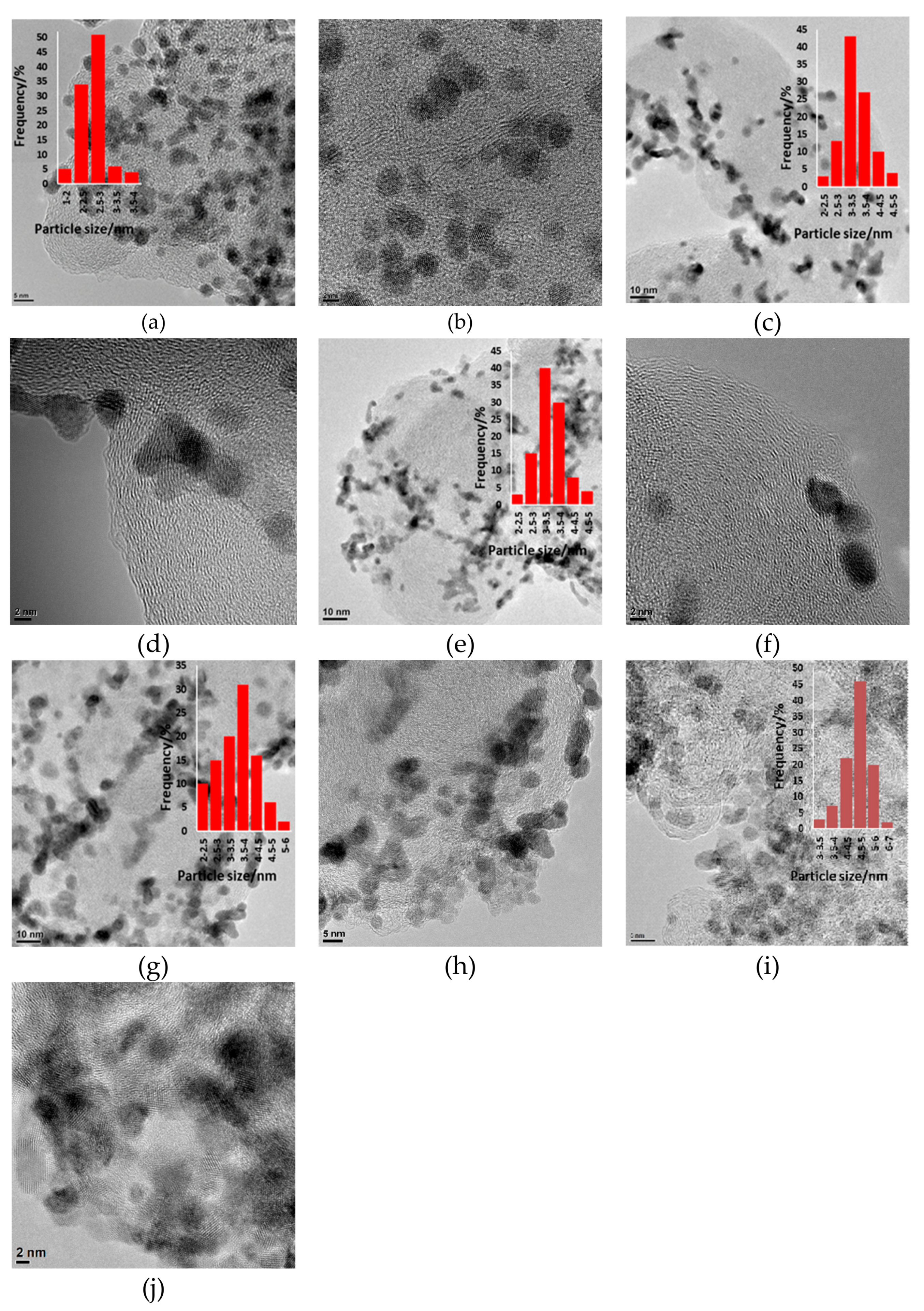
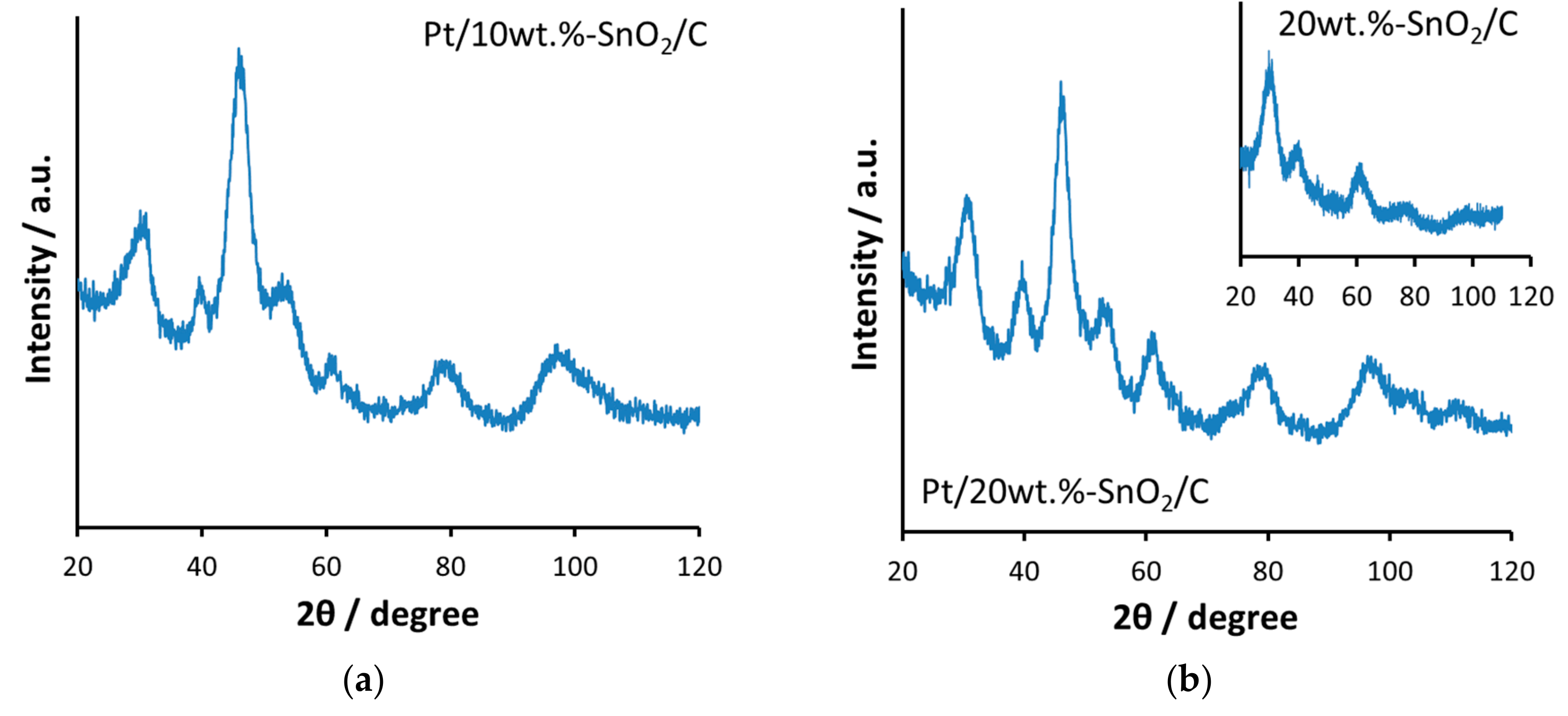
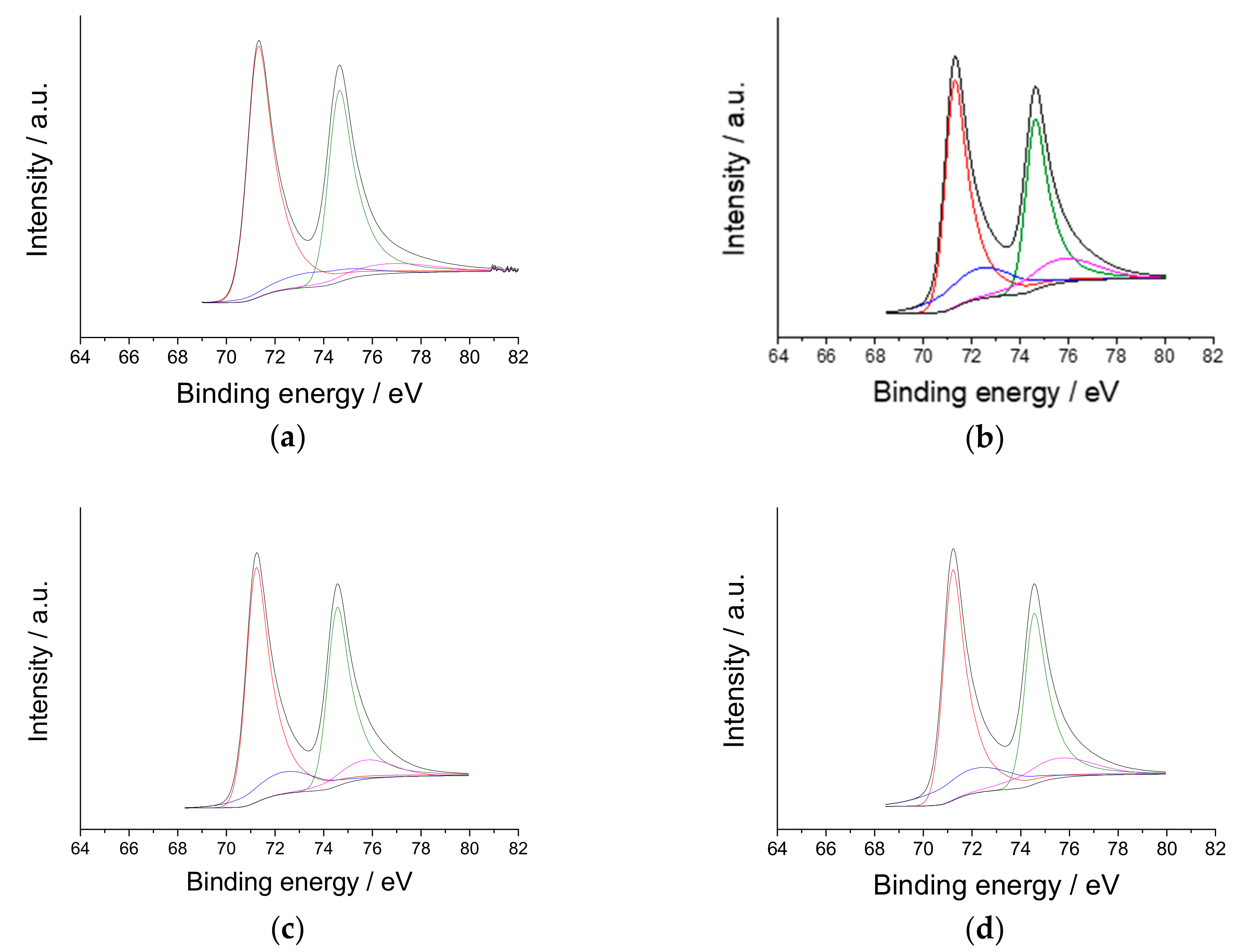
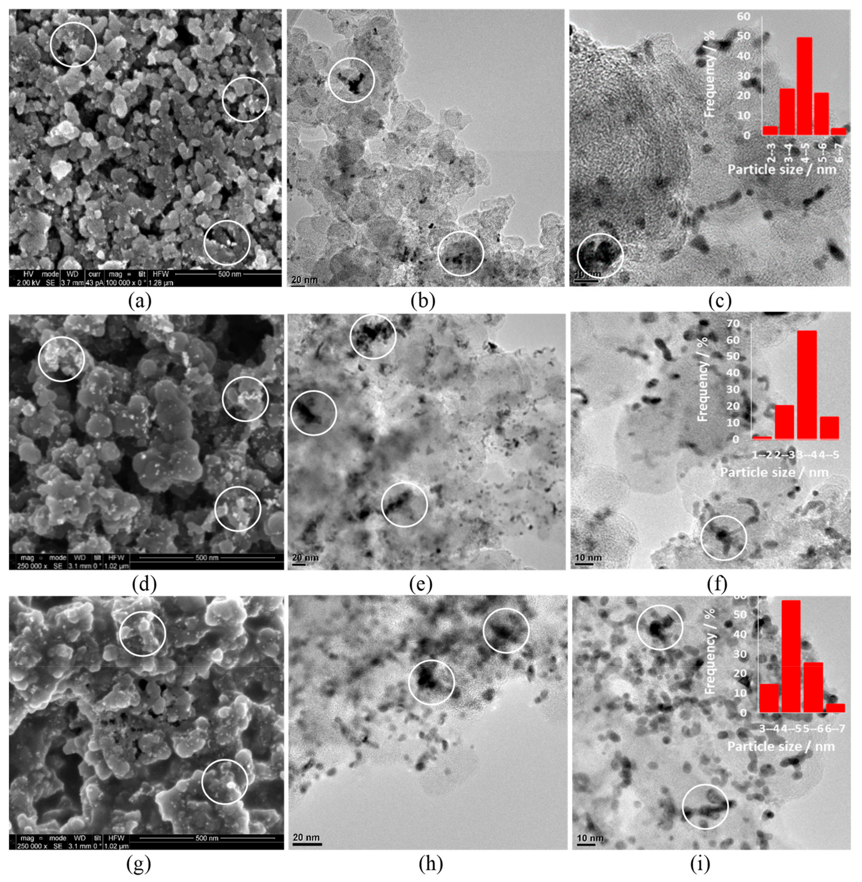
2.1. Catalysts Characterization

Figure 1 shows TEM images of Pt/x-SnO2/C catalyst (where the catalyst mass content of Pt is 20 wt % and x = 5, 10, 20, 40 wt % is the mass content of tin dioxide in the composite support), 20wt %-SnO2/C, and Pt/C. The actual Pt and Sn content of all catalysts was confirmed by EDS measurements (given in Table 1) and thermal gravimetric measurements. The obtained values of the Pt content correspond to the preliminary calculated before the synthesis.
The particle size distribution data were obtained through the processing of the TEM images using the ImageJ software and considering more than 100 particles. A rather narrow particle size distribution for modified carbon-supported catalysts was obtained. The average particle size was ca. 2.7, 3.4, 3.2, and 3.6 nm for Pt/C, Pt/5wt %-SnO2/C, Pt/10wt %-SnO2/C, and Pt/20wt %-SnO2/C, respectively. Due to the particle’s agglomeration, the precious determination of particle size is not straightforward and X-ray diffraction data additionally was used below. Particle size for tin dioxide-modified catalysts is close to those for Pt40/C [31,32,33] catalyst but larger than the size of Pt/C catalyst particles and in a good agreement with previous study for Pt20/SnOx8/C and Pt20/SnOx12/C [29].
The morphology of all samples is characterized by the existence of the agglomerates consists of primary nanosized catalyst particles. However, the agglomeration degree increases significantly by increasing of tin oxide content. Pt/10wt %-SnO2/C catalyst morphology is characterized with the most uniform distribution of Pt and tin dioxide particles on the carbon support surface. The average particle size for Pt/40wt %-SnO2/C was ca. 4.6 nm which was the largest in comparison with other samples. The highest agglomeration degree was observed for this sample as well.
Figure 2 shows the XRD-patterns of the catalysts on tin dioxide-modified carbon support. The spectra of both Pt/10wt %-SnO2/C and Pt2/20wt %-SnO2/C samples, in general, are particularly similar to those given in [16,34,35,36]. The diffraction peaks around 31 °, 39 °, and 61° refer to SnO2 (110), (101), and (211) planes which is slightly grown in intensity with increasing tin content and are presented on the XRD pattern of the SnO220/C support sample. Possible overlapping of the SnO2 (110) plane reflection with the (002) plane of the hexagonal structure of Vulcan XC-72 should be considered. The diffraction peaks at ca. 46°, 53°, 81°, and 96° could be related to the (111), (200), (220), and (311) planes of Pt, respectively (all 2 theta angles are given with respect to the spectra obtained using the Co Кα radiation). The presence of a rather small amount of alloyed Pt3Sn (111) could be suggested due to the peak at ca. 46° in the Figure 2a inset which could be disguised by highly intensive Pt (111) reflection in case of supported catalysts.
Pt crystallite average diameter was calculated using Scherrer formula as
d = K λ β cos θ β
where d is the average crystallite size, nm; K is the Scherrer constant (depends on the crystallite shape; and equal to 0.94 for spherical particles with cubic symmetry), λ is the wave length of incident X-rays (0.178897 nm for Co-Kα radiation used in this work), β is the full width of the strongest diffraction peak at half height (radians), θβ is the Bragg angle at the position of peak maximum (degree).
The crystallite size of ca. 2.6, 3.15, 3.05, and 3.92 were obtained for Pt/C, Pt/5wt %-SnO2/C, Pt/10wt %-SnO2/C, Pt/20wt %-SnO2/C, and 20wt %-SnO2/C showing good correlation with the data obtained by TEM data analysis given above [37]. A difference in obtained values is due to any deviations from the assumptions accepted by both approaches (dislocations, non-spherical particles shape, particle agglomeration, etc.). Pt particle/crystalline size increase with increasing of the tin oxide content due to the particle agglomeration and the selective Pt reduction near the oxide particles located on the carbon support surface previously.
The increase in tin dioxide content provided a proportional decrease in porosity, specific surface area, and average pore diameter of the support compared with the Pt/C. In particular, the specific surface area decreased from 210 m2g−1 (pure carbon support) to 176 m2g−1 (support with 20 wt % of tin dioxide) and 145 m2g−1 (support with 40 wt % of tin dioxide). This trend is less pronounced for the low tin dioxide contents of ca. 0–10 wt %. Specific surface area decreasing leads to the worse Pt and tin dioxide particles distribution over the carbon support surface and catalyst EASA decreasing (as shown in the following sections).
The obtained XPS spectrums of studied catalysts contain Pt 4f7/2/Pt 4f5/2 doublets suggesting metallic Pt0 and (at higher binding energy) PtOads and/or Pt(OH)2 [27] due to partial surface oxidation of the Pt metal nanoparticles. The XPS spectrum of Pt20/C and Pt20/SnO210/C are given in Figure 3.
The binding energy of Pt 4f7/2 in Pt/10wt %-SnO2/C and Pt/20wt %-SnO2/C are given in Table 2 and exhibit a slight downshift (0.1 eV) compared to the Pt/C which is in a good agreement with the literature data [26]. This result confirms the electron transfer from Sn to Pt providing a more filled Pt d-band and the weaker chemisorption with oxygen-containing species, such as OHads [22,28]. Furthermore, the obtained Pt/10wt %-SnO2/C and Pt/20wt %-SnO2/C catalysts exhibits 0.5–0.55 eV higher Sn 3d5/2 binding energy (487.2 and 487.25 eV, respectively) than pure SnO2 nanoparticles (486.70 eV [38]) which are in good agreement with [22,27], suggesting the electron transfer from tin oxide. The SMSI effect in the prepared Pt/x-SnO2/C catalysts induced by the formation of the Pt-SnO2 clusters in which the electron donation from the oxide to Pt metal takes place enhances electron density on the latter and providing higher activity and stability of Pt nanoparticles [27]. The obtained results confirm that the SMSI effect exists but due to the low value of Pt 4f7/2 binding energy shift its influence is expected to be limited.

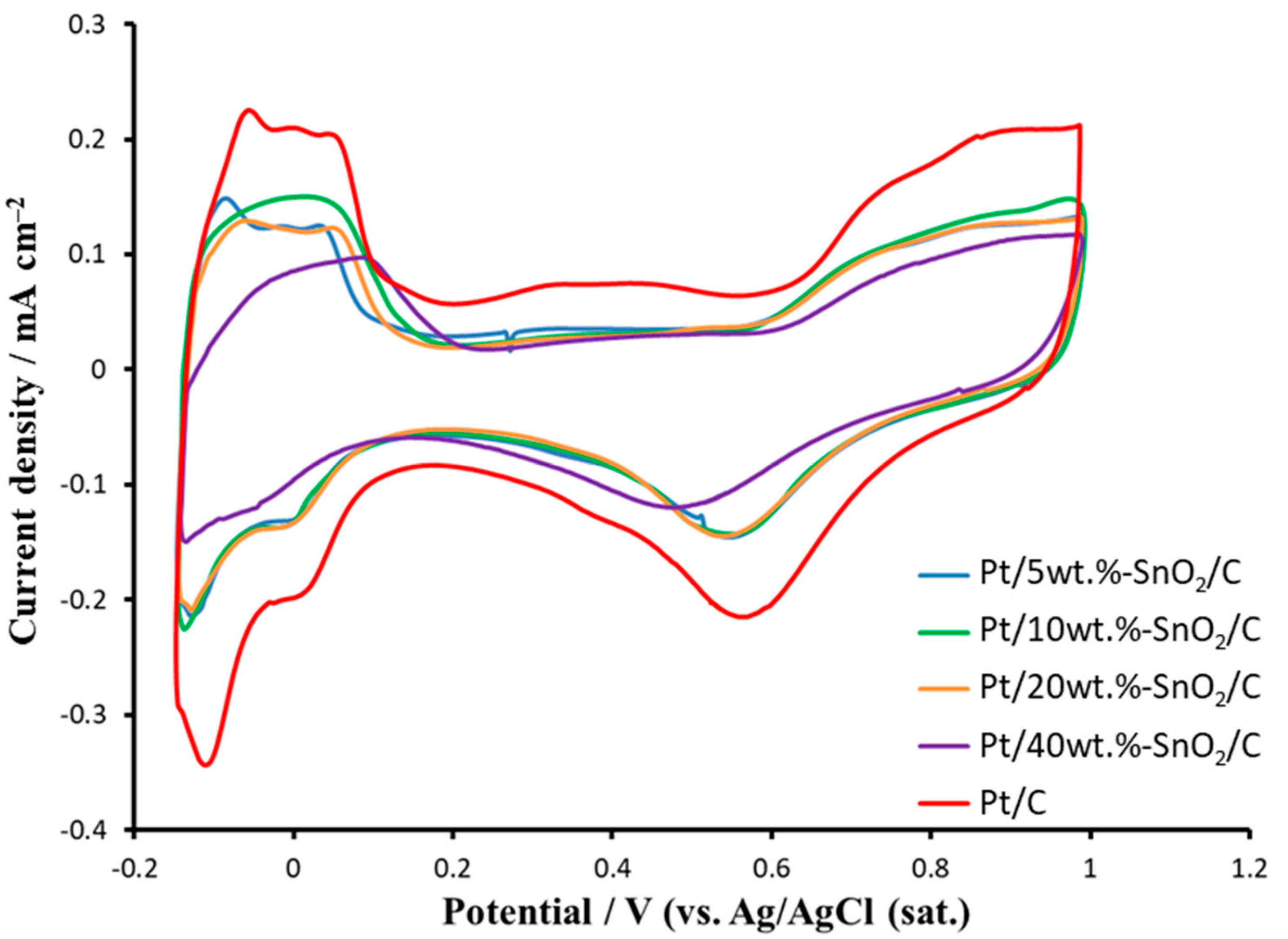
2.2. Electrochemical Studies

Figure 4 presents the cyclic voltammograms (CVs) of Pt/SnO2x/C catalysts and Pt/C. The EASA value is 83, 55, 57, 51, and 27 m2g−1 Pt of Pt/C, Pt/5wt %-SnO2/C, Pt/10wt %-SnO2/C, Pt/20wt %-SnO2/C, and Pt/40wt %-SnO2/C catalyst, respectively. The EASA values of Pt/5wt %-SnO2/C and Pt/10wt %-SnO2/C are in a good agreement with those taken from an average particle size (see Figure 1).
In general, studied catalysts demonstrated well-defined hydrogen adsorption/desorption peaks in the potential region -0.20–0.20 V and the oxygenated species adsorption/desorption peaks at potentials ca. 0.6 and 1.0 V vs Ag/AgCl (sat.) electrode, which are in good agreement with the literature data for Pt-based catalysts [39,40]. Suppression of the currents in the hydrogen adsorption/desorption region is observed when the SnO2 loading increases up to 20 wt %, which can be explained by the more facile adsorption of OH– species which hinders the hydrogen adsorption and by possible blockage of Pt sites [41]. The same phenomenon and/or defects, edge/corner sites, and various distribution of crystal orientations on the surface of Pt nanocatalyst may explain the fact that typical Pt crystal lattice peaks less pronounced and the hydrogen desorption wave shifts to more positive potentials with tin dioxide loading increasing as well [42].
At high concentrations of tin dioxide on the carbon support surface, the formation of large particles agglomerates is observed, which greatly enhances the catalyst structure irregularity. This is most pronounced for the catalyst supported on 40wt %-SnO2/C which is characterized by a significant loss in EASA in comparison with Pt/C. The decrease of carbon black content and the ability of SnO2 nanoparticles to fill all the sites suitable for Pt nanoparticle nucleation could also contribute to such deterioration of the Pt distribution and low EASA at high SnO2 contents [29]. Due to the low EASA value the Pt20SnO240/C sample is not discussed in the following sections.

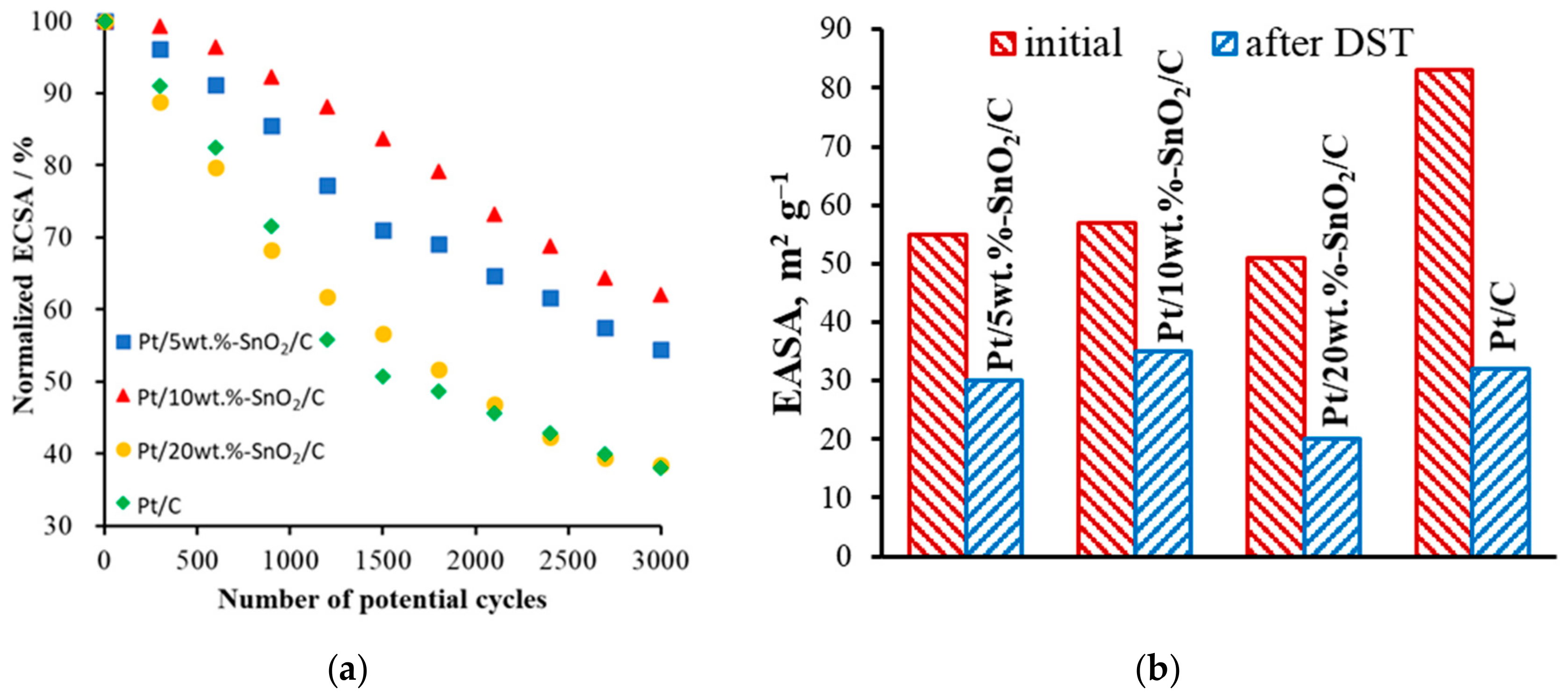
2.3. Durability Stress-Testing

The accelerated stress testing approach consisting of the potential cycling has shown itself to be the fastest and effective way to assess the corrosion resistance of ORR catalysts. The most intense dissolution of platinum is observed at a potential of 1.1 V and the potential cycling up to the values above this boundary leads to noticeable destruction of the carbon support providing the most severe degradation. There are various conditions for accelerated stress testing presented in the literature [43,44,45,46,47,48].
The carbon support corrosion is of prime importance for the long-term stability of the PEMFC electrocatalytic materials [45]. At potentials 0.6 < E < 1.0 V vs. SHE the carbon support oxidation is catalyzed by the presence of Pt nanoparticles [49,50]. From the other hand, at higher potentials Pt nanoparticles are prone to passivate, its dissolution is retarded and the carbon support corrosion is most important [46,51]. Thus, the durability stress testing (DST) approach at the potential range of 0.6–1.2 V vs. Ag/AgCl (sat.) electrode (described in Experimental Section) provides harsh conditions giving the carbon support corrosion as well as Pt nanoparticles degradation.
For all catalysts, there is a gradual decrease in the EASA values (Figure 5) with an increasing number of cycles associated with such degradation mechanisms as Pt dissolution/redeposition, agglomeration, detachment, and carbon corrosion [51,52,53]. The carbon-support corrosion is expected to be the prevailing degradation mechanisms due to the selected potential range of DST procedure. The pattern of the EASA decreasing is similar for all studied catalysts. The EASA retention values after DST is ca. 55, 62, 38.5, and 38.1% of the Pt/5wt %-SnO2/C, Pt/10wt %-SnO2/C, Pt/20wt %-SnO2/C, and Pt/C, respectively.
The protective effect of tin dioxide coating is clear for the Pt/10wt %-SnO2/C and Pt/5wt %-SnO2/C (Figure 5) catalysts, due to the higher stability against carbon support degradation in comparison with Pt/C. According to [24] the low electrocatalytic activity of Pt/SnO2/C catalysts after DST can be either related to the degradation of the uncovered carbon or to the formation of an amorphous layer of tin oxide on the surface providing poor electrical conductivity. From the other hand, the weak stability against degradation of the Pt/20wt %-SnO2/C could be related to the initially improper catalyst structure. Significant agglomeration and non-uniform distribution of SnO2 particles, as well as the presence of carbon black defective structure (uncovered carbon) led to the heavy deterioration of electronically conductive network of the catalyst layer and to the sharp EASA decreasing (even faster than in the case of Pt/C). From the other hand, the formation of heterogeneous Pt-SnO2 clusters may prevent platinum particle agglomeration, providing additional stabilizing effect [30].
Additional TEM studies of catalytic layers being aged were carried out after the DST (Figure 6).
Figure 6 shows pronounced agglomeration of platinum particles (marked with white circles) for all samples after DST. The average particle size for catalysts after DST was 5.2, 4.8 and 5.8 nm for Pt/5wt %-SnO2/C, Pt/10wt %-SnO2/C, Pt/20wt %-SnO2/C, respectively. Significant changes in the catalysts structure after DST is observed for Pt/20wt %-SnO2/C (as could be seen on Figure 6g,h,i). The catalyst is characterized by the rapid destruction of the catalytic layer structure and layer integrity leading to a significant drop in EASA value. The initial non-uniform catalyst structure promotes the fast catalyst degradation even with the SnO2 loading is high. According to [47], the durability behavior of various carbon supports in the corrosion process is determined not only by their surface area but also by the number of defective carbon sites. It could be suggested that the increasing of SnO2 loading do not leads to higher carbon support coverage, but to the increasing of the particles size. All studied catalysts suffered from the degradation of carbon support defects and the Pt-SnO2 cluster structure increases the stability of covered carbon and Pt particles but nor the uncovered carbon support. It could be suggested that the increasing of SnO2 loading do not leads to the higher carbon support coverage, but to the increasing of the particles size (Figure 1). Finally, low SnO2 content of ca. 5–10 wt % provides significant increasing of the catalyst stability due to the Pt-SnO2 hetero-clusters formation, the uniform cluster dispersion and optimal catalyst layer structure.

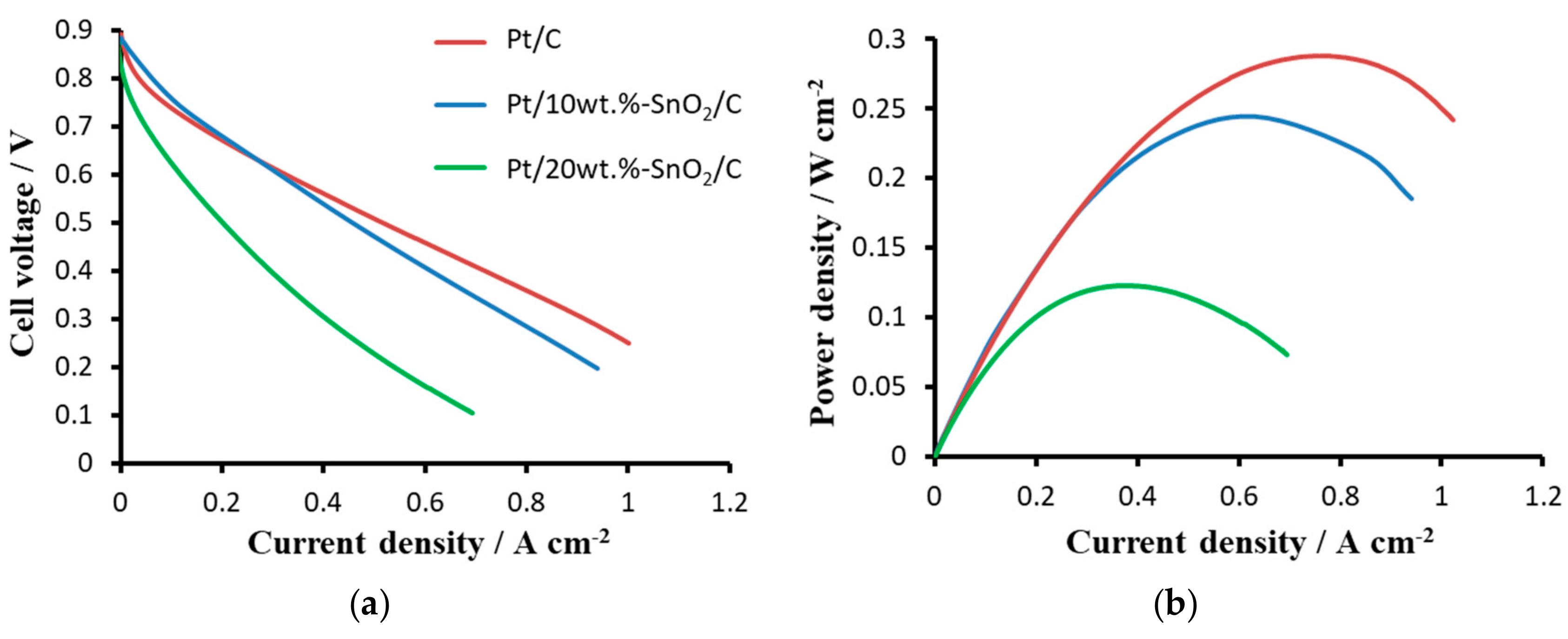
2.4. Fuel Cell Testing

Figure 7 presents steady-state performance data of investigated PEMFC membrane electrode assemblies (MEAs). According to the polarization curves given in Figure 7 at low current densities the performance of Pt/10wt %-SnO2/C catalyst is higher. This result could be related to the higher ORR activity of Pt-SnO2 clusters [23] provided by the interaction of Pt and SnO2. At high current densities the MEA ohmic losses dominates and the lower performance of the Pt/10wt %-SnO2/C could be associated with higher catalytic layer resistance coming from the SnO2 phase [24] lowering the EASA.
The worse performance of the Pt20SnO220/C in comparison with Pt20SnO210/C and Pt20/C is related to the large SnO2 content which leads to the significant particle’s agglomeration degree, non-uniform distribution of Pt and SnO2 particles. High SnO2 content also may provide too dense catalytic layer with small sized pores and/or low porosity which hinders the oxygen diffusion to the Pt active sites [7].
The 5–10 wt % of SnO2 content provides the appropriate catalytic layer structure with sufficiently high EASA, uniform dispersion of Pt-SnO2 clusters, and high carbon support corrosion resistance. This result generally associated with the existence of SMSI which provide the increased stability of the catalyst and optimal catalytic nanoparticles morphology, higher EASA value and catalytic layer structure.

3. Materials and Methods

3.1. Preparation of Pt/SnO2/C Catalysts

3.1.1. Preparation of SnO2 Nanoparticles

The calculated amount of SnCl2·2H2O was dissolved in ethylene glycol (EG) solution contained small amount of DI water. The mixture was ultrasonicated and added to three-necked flask with EG under magnetic stirring. Magnetic stirring was maintained for half an hour at room temperature. After that, the obtained solution was rapidly heated up to 190 °C and boiled for 3 hours with constant magnetic stirring under atmospheric pressure until the color of the solution was changed to yellow indicating the formation of SnO2 colloidal particles [16]. The obtained colloidal solution was cooled down to room temperature.

3.1.2. Preparation of SnO2/C Composite Support

The x-SnO2/C composite support was prepared according to the procedure described in [29]. In brief, the suspension of the calculated amount of the carrier (Vulcan XC-72, Cabot Corporation, Boston, MA, USA), DI H2O and isopropyl alcohol was prepared by mixing. The obtained mixture was ultrasonicated and added dropwise to the colloidal dispersion of SnO2/Sn particles under magnetic stirring. The colloidal solution was preheated to 50 °C. The particle adsorption on the support was carried out for 48 hours under constant stirring at atmospheric pressure. The mass content of SnO2/Sn particles in the SnO2/C composite varied from 5 to 40 wt %.

3.1.3. Preparation of Catalyst Pt/SnO2/C

The preparation of the platinum electrocatalyst on carbon support was carried out using the polyol approach in ethylene glycol (EG) [54]. The aqueous solution of H2PtCl6 2H2O was used as the Pt nanoparticles precursor. The H2PtCl6 2H2O solution was added dropwise to the support (SnO2/C or C) colloid solution under magnetic stirring. Magnetic stirring was maintained for half an hour using argon bubbling at room temperature. After that, the temperature gradually raised (1 °C/min.) up to 75 °C and the precursor adsorption process was carried out for 2 hours. Then the temperature was quickly raised up to 180 °C and the reduction of platinum was carried out for 1 hour. Then the mixture was cooled and a few drops of 2 M HCl solution were added in order to reduce the solution pH to ca. 6 and then the catalyst precipitation was filtered and washed using DI water. The resulting catalyst was dried in oven at 70 °C overnight.

3.2. Structural and Morphological Studies

The diffractograms were recorded using the D8 Advance (Bruker, Billerica, MA, USA) using Co Кα - radiation at 2ϑ = 20 – 120° with a step of Δ2ϑ = 0.07°. A scanning/transmission electron microscope Titan 80–300 (Thermo-Fisher Scientific, Beverly, MA, USA) equipped with energy dispersive X-ray spectrometer (EDAX, Mahwah, NJ, USA) was used to study the supports and catalysts morphology. The XPS studies were performed using a PHOIBOS 150 (SPECS, Berlin, Germany) hemispherical analyzer (Al Kα radiation) with 1486.61 eV photon energy at DE = 0.2 eV. The BET specific surface area of synthesized catalysts was determined using Tristar 3000 (Micromeritics, Norcross, GA, USA) in the relative pressure range from 10–6 to 0.99.

3.3. Electrochemical Studies

Catalytic inks were made by mixing of the electrocatalyst in 1:1 isopropanol/water solution with the following ultrasonication for a half of hour at room temperature. Then, the resulting catalytic ink aliquot was pipetted onto the smooth titanium foil electrode forming a thin catalyst layer. Then the titanium electrode was dried until complete removal of the solvent.
The cyclic voltammograms (CVs) were measured in N2-saturated 0.5M H2SO4 at 25 °C using a conventional three-electrode glass cell. The measurements were performed using a Solartron 1285 (AMETEK, Inc., Berwyn, PA, USA) potentiostat. The catalyst’s EASA was calculated using the hydrogen adsorption–desorption peaks at –0.15–0.2 V vs. Ag/AgCl (sat.) as described in [29,54].
Electrocatalysts were subjected to a DST [55] by cycling the potential in the range of 0.6–1.2 V vs. Ag/AgCl (sat.) electrode with a sweep rate of 100 mVs−1 for 3000 cycles. A working 0.5M H2SO4 solution was pre-saturated with oxygen before DST cycles. CVs were measured initially and every 300 cycles. Before the CVs measurement, the working solution was purged with inert N2. The degree of degradation of the cathode catalyst was estimated from the change in the EASA, calculated from the CVs.

3.4. Fuel Cell MEAs Fabrication and Testing

MEAs was prepared using Nafion® 212 (DuPont Inc., Wilmington, DE, USA) as the polymer electrolyte membrane and ELAT® LT 1400 W (NuVant Systems Inc., Crown Point, IN, USA) as anode and cathode gas diffusion electrodes (GDEs). The Pt40/C was used as anode catalyst. The Pt20/C, Pt/10wt %-SnO2/C, and Pt/20wt %-SnO2/C were used as cathode catalysts. The Pt loading of both anode and cathode electrocatalytic layers were 0.5 mg cm–2. Catalytic layers were made through the catalytic inks air-spraying onto the GDE surface as described in [56] using 15 wt % Nafion® ionomer content. The MEA was clamped into the titanium test cell as described in [31,57]. MEAs testing was carried out using pure dry hydrogen and air at relative humidity of 100%. The cell temperature was 40 °C.

4. Conclusions

The influence of composition and structure of carbon-supported Pt-SnO2 hetero-clusters onto their electrocatalytic activity and durability toward ORR in PEMFCs has been investigated. It was shown that formation of Pt-SnO2 clusters has a significant impact on electrochemical performances, structure, and morphology of catalysts. The approaches used to prepare the SnO2/C and Pt20SnO2x/C (where C is Vulcan XC-72 carbon black) hybrid supports and electrocatalysts significantly improved the carbon support stability and catalytic layers durability. XPS and TEM confirm the formation of Pt-SnO2 hetero-clusters with a strong interaction between Pt and SnO2 nanoparticles. The SnO2 content of ca. 10 wt % ensures an optimal catalytic layer structure and morphology providing uniform distribution of Pt-SnO2 clusters over the carbon support surface without significant particle agglomeration. The usage of higher SnO2 content leads to the significant particle agglomeration and non-uniform distribution of SnO2 particles leading to the lower EASA value and worse PEMFC cathode performance. Pt20/SnO210/C catalyst demonstrates increased durability in course of accelerated stress testing due to the high stability of SnO2 and its interaction with Pt. The EASA retention of Pt/10wt %-SnO2/C and Pt/C is ca. 62 and 38.1%, respectively. These values correspond to the 35.3 and 31.2 m2 g–1 Pt, respectively. Moreover, the PEMFC cathode performance of the Pt/10wt %-SnO2/C is comparable with those of Pt/C.

Author Contributions

Conceptualization, V.N.F., N.A.I., D.D.S., and A.S.P.; Methodology, D.D.S. and N.A.I.; Validation, A.S.P., I.V.P., and S.A.G.; Investigation, D.D.S., N.A.I., R.G.C., and N.N.P.; Resources, V.N.F. and M.Y.P.; Writing—original draft preparation, N.A.I. and D.D.S; Writing—review and editing, A.S.P., I.V.P., V.N.F., and S.A.G.; Visualization, D.D.S., N.A.I., and I.V.P.; Supervision, V.N.F.; Project administration, V.N.F.; Funding acquisition, V.N.F.

Funding

This research was conducted with financial support of the Ministry of Science and Higher Education of the Russian Federation (unique project identifier RFMEFI60417X0171) in National Research Center “Kurchatov Institute”, Russia.

Conflicts of Interest

The authors declare no conflict of interest.

References

  1. Pan, Z.F.; An, L.; Wen, C.Y. Recent advances in fuel cells based propulsion systems for unmanned aerial vehicles. Appl. Energy 2019, 240, 473–485. [Google Scholar] [CrossRef]
  2. Banham, D.; Ye, S. Current Status and Future Development of Catalyst Materials and Catalyst Layers for Proton Exchange Membrane Fuel Cells: An Industrial Perspective. ACS Energy Lett. 2017, 2, 629–638. [Google Scholar] [CrossRef]
  3. Baranov, I.E.; Nikolaev, I.I.; Pushkarev, A.S.; Pushkareva, I.V.; Kalinnikov, A.A.; Fateev, V.N. Numerical Modeling of Polymer Electrolyte Fuel Cell Catalyst Layer with Different Carbon Supports. Int. J. Electrochem. Sci. 2018, 13, 8673–8685. [Google Scholar] [CrossRef]
  4. Hara, M.; Lee, M.; Liu, C.H.; Chen, B.H.; Yamashita, Y.; Uchida, M.; Uchida, H.; Watanabe, M. Electrochemical and Raman spectroscopic evaluation of Pt/graphitized carbon black catalyst durability for the start/stop operating condition of polymer electrolyte fuel cells. Electrochim. Acta 2012. [Google Scholar] [CrossRef]
  5. Anwar, M.T.; Yan, X.; Asghar, M.R.; Husnain, N.; Shen, S.; Luo, L.; Zhang, J. Recent advances in hybrid support material for Pt-based electrocatalysts of proton exchange membrane fuel cells. Int. J. Energy Res. 2018, 1–28. [Google Scholar] [CrossRef]
  6. Kou, R.; Shao, Y.; Mei, D.; Nie, Z.; Wang, D.; Wang, C.; Viswanathan, V.V.; Park, S.; Aksay, I.A.; Lin, Y.; et al. Stabilization of electrocatalytic metal nanoparticles at metal-metal oxide-graphene triple junction points. J. Am. Chem. Soc. 2011, 133, 2541–2547. [Google Scholar] [CrossRef] [PubMed]
  7. Nakazato, Y.; Kawachino, D.; Noda, Z.; Matsuda, J.; Lyth, S.M.; Hayashi, A.; Sasaki, K. PEFC Electrocatalysts Supported on Nb-SnO2 for MEAs with High Activity and Durability: Part I. Application of Different Carbon Fillers. J. Electrochem. Soc. 2018, 165, F1154–F1163. [Google Scholar] [CrossRef]
  8. Pushkarev, A.S.; Pushkareva, I.V.; Du Preez, S.P.; Ivanova, N.A.; Grigoriev, S.A.; Slavcheva, E.P.; Bessarabov, D.G.; Fateev, V.N.; Aliyev, A.S. Iridium catalyst supported on conductive titanium oxides for polymer electrolyte membrane electrolysis. Chem. Probl. 2019, 17, 9–15. [Google Scholar] [CrossRef]
  9. Du, L.; Shao, Y.; Sun, J.; Yin, G.; Liu, J.; Wang, Y. Advanced catalyst supports for PEM fuel cell cathodes. Nano Energy 2016, 29, 314–322. [Google Scholar] [CrossRef] [Green Version]
  10. Fabbri, E.; Rabis, A.; Chino, Y.; Uchida, M.; Schmidt, T.J. Boosting Pt oxygen reduction reaction activity by tuning the tin oxide support. Electrochem. Commun. 2017, 83, 90–95. [Google Scholar] [CrossRef]
  11. Geiger, S.; Kasian, O.; Mingers, A.M.; Mayrhofer, K.J.J.; Cherevko, S. Stability limits of tin-based electrocatalyst supports. Sci. Rep. 2017, 7, 4595. [Google Scholar] [CrossRef] [PubMed]
  12. Cognard, G.; Ozouf, G.; Beauger, C.; Dubau, L.; López-Haro, M.; Chatenet, M.; Maillard, F. Insights into the stability of Pt nanoparticles supported on antimony-doped tin oxide in different potential ranges. Electrochim. Acta 2017, 245, 993–1004. [Google Scholar] [CrossRef]
  13. Frolova, L.A.; Dobrovolsky, Y.A.; Bukun, N.G. Oxide supported platinum electrocatalysts for hydrogen and alcohol fuel cells. Russ. J. Electrochem. 2011, 47, 697–708. [Google Scholar] [CrossRef]
  14. Zhang, K.; Feng, C.; He, B.; Dong, H.; Dai, W.; Lu, H.; Zhang, X. An advanced electrocatalyst of Pt decorated SnO2/C nanofibers for oxygen reduction reaction. J. Electroanal. Chem. 2016, 781, 198–203. [Google Scholar] [CrossRef]
  15. Hoque, M.A.; Higgins, D.C.; Hassan, F.M.; Choi, J.-Y.; Pritzker, M.D.; Chen, Z. Tin oxide—Mesoporous carbon composites as platinum catalyst supports for ethanol oxidation and oxygen reduction. Electrochim. Acta 2014, 121, 421–427. [Google Scholar] [CrossRef]
  16. Jiang, L.; Sun, G.; Zhou, Z.; Sun, S.; Wang, Q.; Yan, S.; Li, H.; Tian, J.; Guo, J.; Zhou, B.; et al. Size-Controllable Synthesis of Monodispersed SnO2 Nanoparticles and Application in Electrocatalysts. J. Phys. Chem. B 2005, 109, 8774–8778. [Google Scholar] [CrossRef]
  17. Huang, H.; Liu, Y.; Gao, Q.; Ruan, W.; Lin, X.; Li, X. Rational construction of strongly coupled metal-metal oxide-graphene nanostructure with excellent electrocatalytic activity and durability. ACS Appl. Mater. Interfaces 2014, 6, 10258–10264. [Google Scholar] [CrossRef] [PubMed]
  18. Labbé, F.; Disa, E.; Ahmad, Y.; Guérin, K.; Asset, T.; Maillard, F.; Chatenet, M.; Metkemeijer, R.; Berthon-Fabry, S. Tin dioxide coated carbon materials as an alternative catalyst support for PEMFCs: Impacts of the intrinsic carbon properties and the synthesis parameters on the coating characteristics. Microporous Mesoporous Mater. 2018, 271, 1–15. [Google Scholar] [CrossRef]
  19. Kuriganova, A.B.; Smirnova, N.V. Pt/SnOx-C composite material for electrocatalysis. Mendeleev Commun. 2014, 24, 351–352. [Google Scholar] [CrossRef]
  20. Kuriganova, A.B.; Leontyeva, D.V.; Ivanov, S.; Bund, A.; Smirnova, N.V. Electrochemical dispersion technique for preparation of hybrid MOx–C supports and Pt/MOx–C electrocatalysts for low-temperature fuel cells. J. Appl. Electrochem. 2016, 46, 1245–1260. [Google Scholar] [CrossRef]
  21. Chen, Y.; Wang, J.; Meng, X.; Zhong, Y.; Li, R.; Sun, X.; Ye, S.; Knights, S. Pt-SnO2/nitrogen-doped CNT hybrid catalysts for proton-exchange membrane fuel cells (PEMFC): Effects of crystalline and amorphous SnO2 by atomic layer deposition. J. Power Sources 2013, 238, 144–149. [Google Scholar] [CrossRef]
  22. Zhang, N.; Zhang, S.; Du, C.; Wang, Z.; Shao, Y.; Kong, F.; Lin, Y.; Yin, G. Pt/Tin Oxide/Carbon Nanocomposites as Promising Oxygen Reduction Electrocatalyst with Improved Stability and Activity. Electrochim. Acta 2014, 117, 413–419. [Google Scholar] [CrossRef]
  23. Ruiz Camacho, B.; Morais, C.; Valenzuela, M.A.; Alonso-Vante, N. Enhancing oxygen reduction reaction activity and stability of platinum via oxide-carbon composites. Catal. Today 2013. [Google Scholar] [CrossRef]
  24. Labbé, F.; Asset, T.; Chatenet, M.; Ahmad, Y.; Guérin, K.; Metkemeijer, R.; Berthon-Fabry, S. Activity and Durability of Platinum-Based Electrocatalysts with Tin Oxide–Coated Carbon Aerogel Materials as Catalyst Supports. Electrocatalysis 2019, 10, 156–172. [Google Scholar] [CrossRef]
  25. Kowal, A.; Gojković, S.L.; Lee, K.-S.; Olszewski, P.; Sung, Y.-E. Synthesis, characterization and electrocatalytic activity for ethanol oxidation of carbon supported Pt, Pt–Rh, Pt–SnO2 and Pt–Rh–SnO2 nanoclusters. Electrochem. Commun. 2009, 11, 724–727. [Google Scholar] [CrossRef]
  26. Hussain, S.; Kongi, N.; Erikson, H.; Rähn, M.; Merisalu, M.; Matisen, L.; Paiste, P.; Aruväli, J.; Sammelselg, V.; Estudillo-Wong, L.A.; et al. Alonso-Vante, N. Platinum nanoparticles photo-deposited on SnO2-C composites: An active and durable electrocatalyst for the oxygen reduction reaction. Electrochim. Acta 2019, 316, 162–172. [Google Scholar] [CrossRef]
  27. Jiménez-Morales, I.; Cavaliere, S.; Jones, D.; Rozière, J. Strong metal–support interaction improves activity and stability of Pt electrocatalysts on doped metal oxides. Phys. Chem. Chem. Phys. 2018, 20, 8765–8772. [Google Scholar] [CrossRef] [PubMed]
  28. Yin, M.; Xu, J.; Li, Q.; Jensen, J.O.; Huang, Y.; Cleemann, L.N.; Bjerrum, N.J.; Xing, W. Highly active and stable Pt electrocatalysts promoted by antimony-doped SnO2 supports for oxygen reduction reactions. Appl. Catal. B Environ. 2014, 144, 112–120. [Google Scholar] [CrossRef]
  29. Pushkarev, A.; Pushkareva, I.; Ivanova, N.; du Preez, S.; Bessarabov, D.; Chumakov, R.; Stankevich, V.; Fateev, V.; Evdokimov, A.; Grigoriev, S. Pt/C and Pt/SnOx/C Catalysts for Ethanol Electrooxidation: Rotating Disk Electrode Study. Catalysts 2019, 9, 271. [Google Scholar] [CrossRef]
  30. Yang, G.; Namin, L.M.; Aaron Deskins, N.; Teng, X. Influence of ∗OH adsorbates on the potentiodynamics of the CO2 generation during the electro-oxidation of ethanol. J. Catal. 2017, 353, 335–348. [Google Scholar] [CrossRef]
  31. Pushkarev, A.S.; Pushkareva, I.V.; Grigoriev, S.A.; Kalinichenko, V.N.; Presniakov, M.Y.; Fateev, V.N. Electrocatalytic layers modified by reduced graphene oxide for PEM fuel cells. Int. J. Hydrog. Energy 2015, 40, 14492–14497. [Google Scholar] [CrossRef]
  32. Fedotov, A.A.; Grigoriev, S.A.; Millet, P.; Fateev, V.N. Plasma-assisted Pt and Pt–Pd nano-particles deposition on carbon carriers for application in PEM electrochemical cells. Int. J. Hydrog. Energy 2013, 38, 8568–8574. [Google Scholar] [CrossRef]
  33. Fedotov, A.A.; Grigoriev, S.A.; Lyutikova, E.K.; Millet, P.; Fateev, V.N. Characterization of carbon-supported platinum nano-particles synthesized using magnetron sputtering for application in PEM electrochemical systems. Int. J. Hydrog. Energy 2013, 38, 426–430. [Google Scholar] [CrossRef]
  34. Jiang, L.; Colmenares, L.; Jusys, Z.; Sun, G.Q.; Behm, R.J. Ethanol electrooxidation on novel carbon supported Pt/SnO x/C catalysts with varied Pt:Sn ratio. Electrochim. Acta 2007, 53, 377–389. [Google Scholar] [CrossRef]
  35. Liu, C.W.; Chang, Y.W.; Wei, Y.C.; Wang, K.W. The effect of oxygen containing species on the catalytic activity of ethanol oxidation for PtRuSn/C catalysts. Electrochim. Acta 2011, 56, 2574–2581. [Google Scholar] [CrossRef]
  36. Li, M.; Zhou, W.P.; Marinkovic, N.S.; Sasaki, K.; Adzic, R.R. The role of rhodium and tin oxide in the platinum-based electrocatalysts for ethanol oxidation to CO2. Electrochim. Acta 2013, 104, 454–461. [Google Scholar] [CrossRef]
  37. Prabhuram, J.; Zhao, T.; Wong, C.; Guo, J. Synthesis and physical/electrochemical characterization of Pt/C nanocatalyst for polymer electrolyte fuel cells. J. Power Sources 2004, 134, 1–6. [Google Scholar] [CrossRef]
  38. Ahn, H.-J.; Choi, H.-C.; Park, K.-W.; Kim, S.-B.; Sung, Y.-E. Investigation of the Structural and Electrochemical Properties of Size-Controlled SnO2 Nanoparticles. J. Phys. Chem. B 2004, 108, 9815–9820. [Google Scholar] [CrossRef]
  39. Pozio, A.; Francesco, M.D.; Cemmi, A.; Cardellini, F.; Giorgi, L.; De Francesco, M.; Cemmi, A.; Cardellini, F.; Giorgi, L. Comparison of high surface Pt/C catalysts by cyclic voltammetry. J. Power Sources 2002, 105, 13–19. [Google Scholar] [CrossRef]
  40. Gasteiger, H.A.; Kocha, S.S.; Sompalli, B.; Wagner, F.T. Activity benchmarks and requirements for Pt, Pt-alloy, and non-Pt oxygen reduction catalysts for PEMFCs. Appl. Catal. B Environ. 2005, 56, 9–35. [Google Scholar] [CrossRef]
  41. Rizo, R.; Sebastián, D.; Lázaro, M.J.; Pastor, E. On the design of Pt-Sn efficient catalyst for carbon monoxide and ethanol oxidation in acid and alkaline media. Appl. Catal. B Environ. 2017, 200, 246–254. [Google Scholar] [CrossRef] [Green Version]
  42. Jerkiewicz, G. Electrochemical Hydrogen Adsorption and Absorption. Part 1: Under-potential Deposition of Hydrogen. Electrocatalysis 2010, 1, 179–199. [Google Scholar] [CrossRef]
  43. Yang, P.; Wu, X.; Xie, Z.; Wang, P.; Liu, C.; Huang, Q. Durability improving and corrosion-resistance mechanism of graphene oxide modified ultra-thin carbon paper used in PEM fuel cell. Corros. Sci. 2018, 130, 95–102. [Google Scholar] [CrossRef]
  44. Zhang, J.; Zhang, H.; Wu, J.; Zhang, J. Techniques for PEM Fuel Cell Testing and Diagnosis; Elsevier: Amsterdam, The Netherlands, 2013. [Google Scholar]
  45. Castanheira, L.; Silva, W.O.; Lima, F.H.B.; Crisci, A.; Dubau, L.; Maillard, F. Carbon Corrosion in Proton-Exchange Membrane Fuel Cells: Effect of the Carbon Structure, the Degradation Protocol, and the Gas Atmosphere. ACS Catal. 2015, 5, 2184–2194. [Google Scholar] [CrossRef]
  46. Kuzov, A.V.; Tarasevich, M.R.; Bogdanovskaya, V.A.; Modestov, A.D.; Tripachev, O.V.; Korchagin, O.V. Degradation processes in hydrogen—Air fuel cell as a function of the operating conditions and composition of membrane–electrode assemblies. Russ. J. Electrochem. 2016, 52, 705–715. [Google Scholar] [CrossRef]
  47. Avakov, V.B.; Aliev, A.D.; Bogdanovskaya, V.A.; Ivanitskii, B.A.; Kazanskii, L.P.; Kapustin, A.V.; Korchagin, O.V.; Landgraf, I.K.; Tarasevich, M.P.; Chalykh, A.E. Variations in the structure and electrochemical characteristics of membrane electrode assemblies during the endurance testing of hydrogen-air fuel cells. Russ. J. Phys. Chem. A 2015, 89, 887–893. [Google Scholar] [CrossRef]
  48. Yuan, X.-Z.; Li, H.; Zhang, S.; Martin, J.; Wang, H. A review of polymer electrolyte membrane fuel cell durability test protocols. J. Power Sources 2011, 196, 9107–9116. [Google Scholar] [CrossRef] [Green Version]
  49. Maillard, F.; Bonnefont, A.; Micoud, F. An EC-FTIR study on the catalytic role of Pt in carbon corrosion. Electrochem. Commun. 2011, 13, 1109–1111. [Google Scholar] [CrossRef]
  50. Linse, N.; Gubler, L.; Scherer, G.G.; Wokaun, A. The effect of platinum on carbon corrosion behavior in polymer electrolyte fuel cells. Electrochim. Acta 2011, 56, 7541–7549. [Google Scholar] [CrossRef]
  51. Zhang, Y.; Chen, S.; Wang, Y.; Ding, W.; Wu, R.; Li, L.; Qi, X.; Wei, Z. Study of the degradation mechanisms of carbon-supported platinum fuel cells catalyst via different accelerated stress test. J. Power Sources 2015, 273, 62–69. [Google Scholar] [CrossRef]
  52. Speder, J.; Zana, A.; Spanos, I.; Kirkensgaard, J.J.K.; Mortensen, K.; Hanzlik, M.; Arenz, M. Comparative degradation study of carbon supported proton exchange membrane fuel cell electrocatalysts—The influence of the platinum to carbon ratio on the degradation rate. J. Power Sources 2014, 261, 14–22. [Google Scholar] [CrossRef]
  53. Pizzutilo, E.; Geiger, S.; Grote, J.-P.; Mingers, A.; Mayrhofer, K.J.J.; Arenz, M.; Cherevko, S. On the Need of Improved Accelerated Degradation Protocols (ADPs): Examination of Platinum Dissolution and Carbon Corrosion in Half-Cell Tests. J. Electrochem. Soc. 2016, 163, F1510–F1514. [Google Scholar] [CrossRef] [Green Version]
  54. Grigoriev, S.A.; Millet, P.; Fateev, V.N. Evaluation of carbon-supported Pt and Pd nanoparticles for the hydrogen evolution reaction in PEM water electrolysers. J. Power Sources 2008, 177, 281–285. [Google Scholar] [CrossRef]
  55. Ivanova, N.A.; Alekseeva, O.K.; Fateev, V.N.; Shapir, B.L.; Spasov, D.D.; Nikitin, S.M.; Presnyakov, M.Y.; Kolobylina, N.N.; Soloviev, M.A.; Mikhalev, A.I.; et al. Activity and durability of electrocatalytic layers with low platinum loading prepared by magnetron sputtering onto gas diffusion electrodes. Int. J. Hydrog. Energy 2019. [Google Scholar] [CrossRef]
  56. Grigoriev, S.A.; Fateev, V.N.; Pushkarev, A.S.; Pushkareva, I.V.; Ivanova, N.A.; Kalinichenko, V.N.; Presnyakov, M.Y.; Wei, X. Reduced Graphene Oxide and Its Modifications as Catalyst Supports and Catalyst Layer Modifiers for PEMFC. Materials 2018, 11, 1405. [Google Scholar] [CrossRef]
  57. Grigor’ev, S.A.; Pushkarev, A.S.; Kalinichenko, V.N.; Pushkareva, I.V.; Presnyakov, M.Y.; Fateev, V.N. Electrocatalytic layers based on reduced graphene oxide for fabrication of low-temperature fuel cells. Kinet. Catal. 2015, 56, 689–693. [Google Scholar] [CrossRef]
Figure 1. TEM-images with individual particle distribution of, Pt/C (a,b); Pt/5wt %-SnO2/C (c,d); Pt/10wt %-SnO2/C (e,f); Pt/20wt %-SnO2/C (g,h); and Pt/40wt %-SnO2/C (i,j).
Catalysts 09 00803 g001
Figure 2. Powder XRD-patterns for Pt/10wt %-SnO2/C (a), Pt/20wt %-SnO2/C (b) and 20wt %-SnO2/C (a, inset). The interplanar distances are given above the lines.
Catalysts 09 00803 g002
Figure 3. Pt 4f7/2 XPS spectrums of the Pt/C (a), Pt/5wt %-SnO2/C (b), Pt/10wt.%-SnO2/C (c) and Pt/20wt.%-SnO2/C (d).
Catalysts 09 00803 g003
Figure 4. CVs for of Pt/C, Pt/5wt %-SnO2/C, Pt/10wt %-SnO2/C, Pt/20wt %-SnO2/C and Pt/40wt %-SnO2/C recorded in 0.5M H2SO4 solution at 25 °C (scan rate 20 mV s−1).
Catalysts 09 00803 g004
Figure 5. The change in EASA values of Pt/20wt %-SnO2/C, Pt/10wt %-SnO2/C, Pt/5wt %-SnO2/C and Pt/C in course of the DST: normalized (a) and absolute values (b) before and after DST.
Catalysts 09 00803 g005
Figure 6. SEM and TEM-images of Pt/5wt %-SnO2/C (ac), Pt/10wt %-SnO2/C (df) and Pt/20wt %-SnO2/C (gi) catalytic layers after DST. Scale bar – 20 nm (b,e,h) and 10 nm (c,f,i). White circles show Pt-agglomerates.
Catalysts 09 00803 g006
Figure 7. Steady-state performance data of MEAs (polarization curves (a) and power density vs. current density (b) curve) equipped with different cathode catalysts: Pt/C, Pt/10wt %-SnO2/C and Pt/20wt %-SnO2/C. Anode catalyst: Pt/C (40 wt % of Pt). Both anode and cathode with Pt loading is ca. 0.5 mg cm−2. Membrane: Nafion® 212. Temperature: 40 °C. The cell is fed by dry hydrogen and air at relative humidity of 100%.
Catalysts 09 00803 g007
Table 1. EDS elemental analysis data.
CatalystPt, wt % Sn, wt % 1C, wt % 1O, wt % 1SnO2, wt % 1
Pt/C19.51-78.651.84-
Pt/5wt %-SnO2/C20.054.0972.843.025.3
Pt/10wt %-SnO2/C19.798.4267.714.0810.7
Pt/20wt %-SnO2/C19.2217.6457.036.1122.4
Pt/40wt %-SnO2/C20.5130.8937.6210.9839.2
1 Calculated using the Sn content.
Table 2. Analysis of the Pt 4f and Sn 3d photoemission lines for Pt/C and Pt/x- SnO2/C catalysts.
CatalystPt 4f7/2Pt 4f5/2
Pt/C71.3274.65
Pt/5wt %-SnO2/C71.2174.61
Pt/10wt %-SnO2/C71.2374.61
Pt/20wt %-SnO2/C71.2074.62

