1. Introduction
Environmental pollution has been one of the hottest topics for the worldwide research community for long years. The presence of VOCs (volatile organic compounds), sulfur-based gases, and nitrogen dioxide in the air is one of the greatest concerns for common people. Therefore, the importance of producing good sensors for these pollutant gases is crucial for safety. To reduce material consumption and waste, these film technologies, likely solvent-free, are needed.
Titanium dioxide is one of the most-used materials in this field for the fabrication of photocatalyst devices and gas sensors [
1,
2,
3]. The doping of pure TiO
2 films with nitrogen atoms is one of the most-used methods to further improve the sensitivity of TiO
2 to the environment thanks to the reduced band gap and a higher achievable conductivity [
4]. The kind of doping of TiO
2 by nitrogen is a debated concern. As a matter of fact, the location of nitrogen species strongly depends on the doping procedure and conditions (e.g., oxygen reach vs. oxygen-poor ambient) [
5]. Shen et al. have found that nitrogen atoms are placed mainly in an interstitial position by doping the TiO
2 through low-energy ion implantation [
6]. Peng et al. have found both interstitial and substitutional nitrogen doping by microwave synthesis [
7]. As a limiting drawback, engineering proper nitrogen incorporation would require processes at relatively high temperatures that are often not compatible with low-cost substrates.
In this framework, what is clear is that competition is established between nitrogen substituting oxygen in the octahedral coordination with titanium atoms and oxygen vacancies since they are mutually correlated. Once integrated into the anatase lattice, nitrogen atoms are solely coordinated to titanium atoms in an arrangement which resembles (but does not coincide with) the nitride one. It is also largely assessed that substitutional nitrogen introduces levels into the anatase bandgap, close to the top of the valence band [
8,
9]. Nitrogen can also arrange in interstitial positions, changing its neighborhood respect to a substitutional position, thus creating a π state 0.74 eV above the valence band [
10].
Doped and porous TiO
2 layers grown by physical deposition would allow low contamination levels into the material and material reproducibility with consequent high production throughput. As the main issue, in situ doping during material growth is difficult to achieve at room temperature. Doping combined with porosity would allow for the raising of surface availability for high reactivity to environmental species. In this framework, we developed a new reactive sputtering method called gig-lox [
11,
12] to grow porous oxides for up-scalable, and therefore industrially compatible, solutions to be applied in high-throughput devices. The novelty of the produced material resides in its spongy fine-branched structure, homogeneously grown in a bottom-up process (≤1000 nm) [
11,
13]. The layered architecture consists of grains separated by mesopores, with an internal structure of branched nanorods embedded in a network of pores. The material is grown at room temperature without the need of any firing process.
In this paper, we exploit a modified gig-lox methodology to grow nitrogen-doped TiO2 porous scaffolds for gas sensing by introducing N2 species at room temperature during the deposition process. Nitrogen incorporation was investigated in detail by several techniques to optimize the atomic arrangement. As a proof-of-concept, thin layers were purposely integrated into resistive devices equipped with micro-hot-plates for local heating with low power consumption. The high surface-to-volume ratio, the high surface reactivity, the pervasive network of voids, and the interconnected TiO2 nano-branches offered by the spongy gig-lox TiO2 layer allowed for getting a good sensitivity to ethanol at a low temperature.
2. Materials and Methods
Depositions of nitrogen-doped TiO
2 layers were performed using a customized Magnetron DC-pulsed Sputtering equipment fabricated by Kenosistec s.r.l. [
13]. The Ar flow-rate was settled at 69 sccm (standard cm
3 per minutes) in all deposition processes. The reference deposition of undoped TiO
2 was done at room temperature, using a power of 140 W, a current of 475 mA and a voltage of 295 V (power loading 6.9 W/cm
2). For doping, 2 sccm or 5 sccm of N
2 were added to oxygen through the same inlet. Glass slices were used as substrates.
Spectroscopic Ellipsometry (SE) analyses were performed using a J.A.Woollam WASE instrument. A vertical configuration was used for the sample that was better suited to transparent samples in order to measure ellipsometric and transmittance data on the same point. Environmental ellipsometric porosimetry measurements were done using a visible (from 370 to 1000 nm) variable-angle spectroscopic ellipsometer (ESM 300 Woollam) with an atmospheric control chamber. Isopropanol (Sigma Aldrich, St. Louis, MO, USA) was chosen as the adsorbing gas. The volume of adsorbed isopropanol was followed through time-resolved measurement of the refractive index variation upon the relative pressure of the adsorbate (P/P0) using the Cauchy models and the Bruggeman Effective Medium Approximation (J A. Woollam CompleteEASE software). The pore size distribution was then plotted using Kelvin’s equation and using a model of cylindrical pores. A PHI ESCA/SAM 5600 Multi equipped with a standard Mg X-ray source was used to perform the XPS analyses. The Binding Energy scale was then calibrated by centering the adventitious/hydrocarbon carbon C 1s at 285.0 eV.
The layer morphology was evaluated by Field Emission-Scanning Electron Microscopy (FE-SEM) in cross-sectional configurations. X-ray diffraction (XRD) analyses were performed by using a D8-Discover Bruker AXS diffractometer, equipped with a Cu Kα source, in symmetric (source and detector move by the same incremental angle) and grazing incidence configuration.
A microheater plate device (MHP) based on a 1.5 µm thin suspended dielectric membrane was obtained through persistent plasma etch of bulk silicon. Over the membrane, a Pt metal layer was shaped to allow heating over 500 °C with a low voltage applied (<2 V). Onto the heater, Pt interdigitated electrodes were tailored to collect charges also from highly resistive sensing layers. Details regarding the micro-hot-plate are provided in a previous paper [
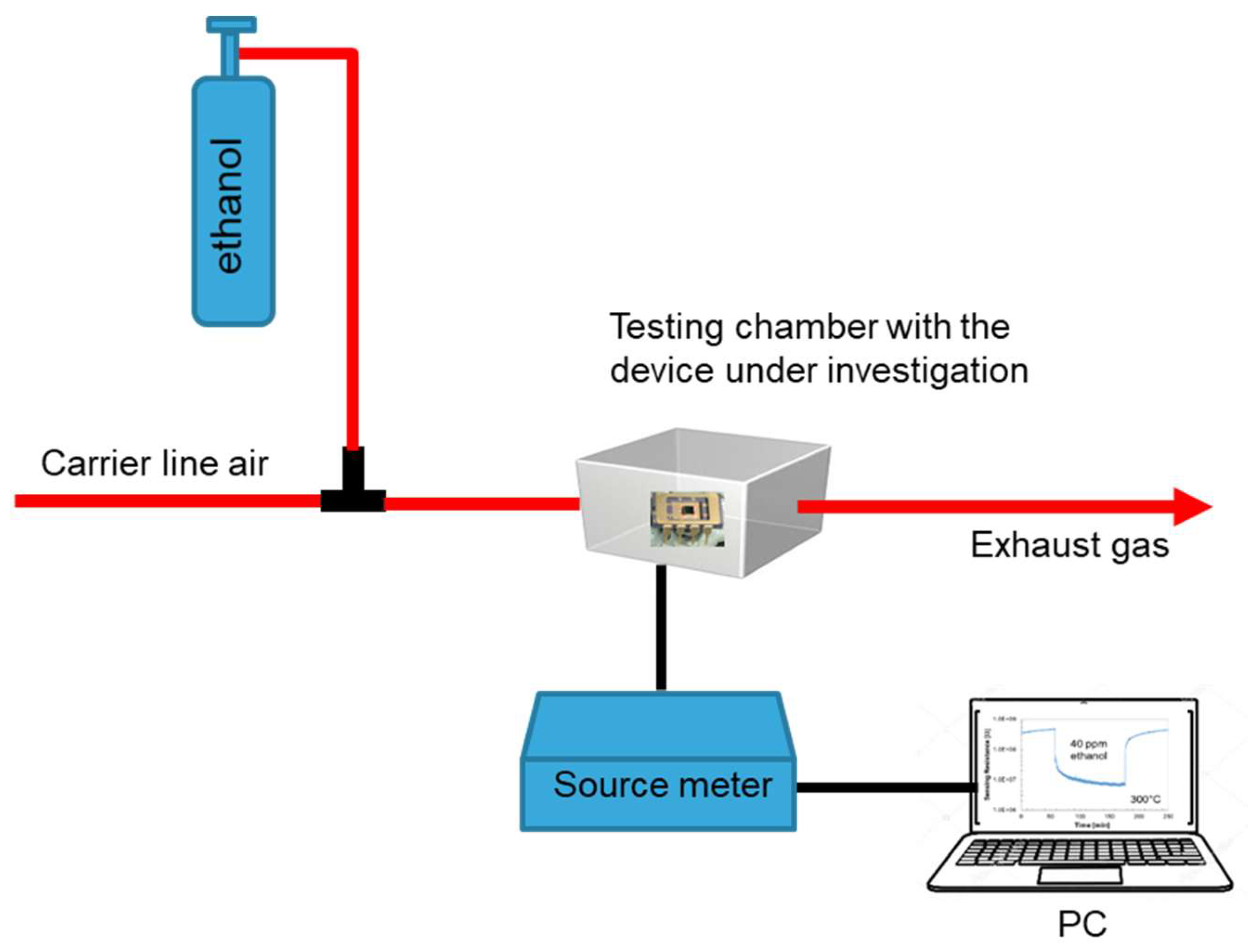
12] where we describe each process step in a comprehensive flowchart. The gas sensors were tested in a chamber filled with ethanol vapors in dry conditions. The N-doped TiO
2 films were integrated into the sensors over the Pt interdigitated electrodes, as the last step process, using a shadow mask.
3. Results and Discussion
Doping of TiO2 layers was performed by modifying the already developed gig-lox method with the additional injection of nitrogen molecules inside the deposition chamber during growth. The growth process was done at room temperature, and this represents the prerequisite of compatibility with the use of flexible substrates.
The active role of nitrogen during growth is primarily testified by the values of deposition rate shown in
Table 1—the higher the content of nitrogen gas, the lower the deposition rate. This finding is likely a consequence of competition between oxidation and nitridation of the Ti species, combined with additional N–O interactions/reactions into the plasma region. This competition is expected to have effects on the nanostructure of the deposited layers. To be comparable, all the grown layers were 420nm-thick.
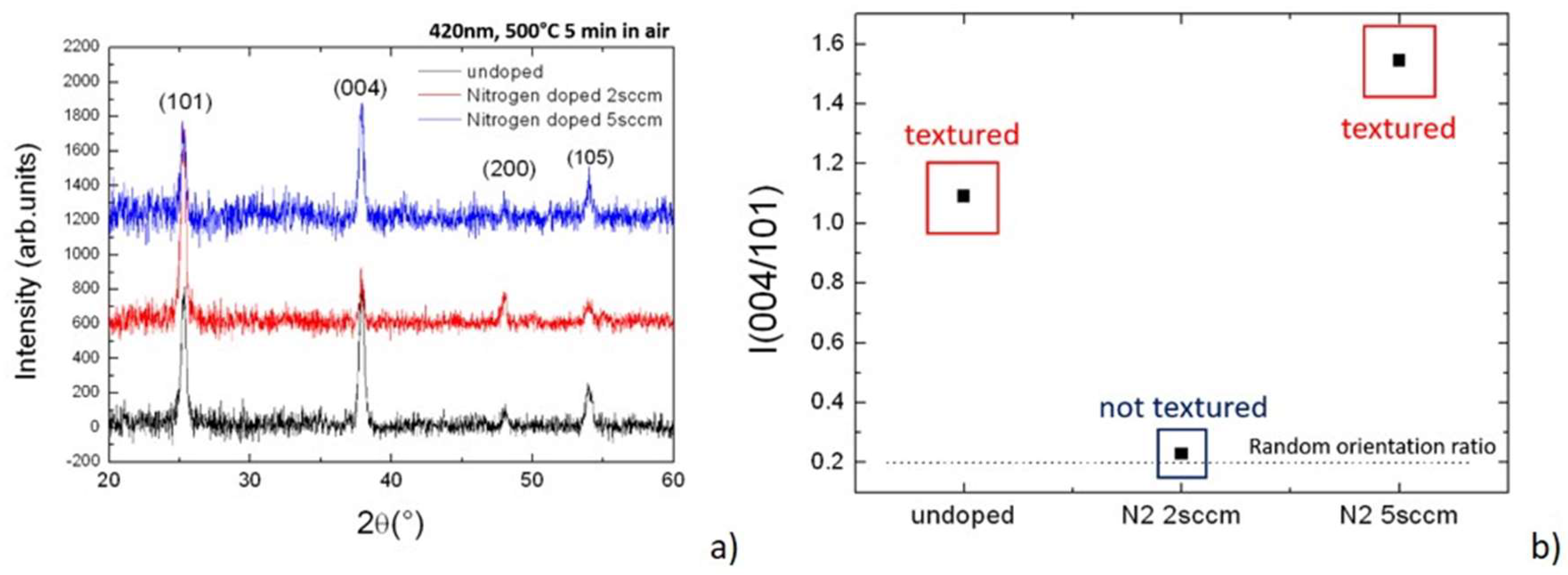
All the starting materials were mostly amorphous. For investigation purposes and to compare the different materials, an internal lattice structuration was triggered by annealing the samples in a furnace at 500 °C. All the lattice structures consequently settled in the anatase arrangement [
14] as depicted by the diffraction patterns of
Figure 1a. No other polymorphisms were present in the layers. Although the structures look similar, a difference was identified in the texturing degree of the grains [
15], a parameter that weighs the reciprocal abundance of the growing planes selected during growth. The related figures of merit are in
Figure 1b wherein the relative intensities of the two main planes, namely the (101) vs. (004), were measured in the different growing conditions. Here, we note the first discontinuity when using 2 sccm of N
2 during growth—this is the only process that produced a randomly oriented set of anatase grains.
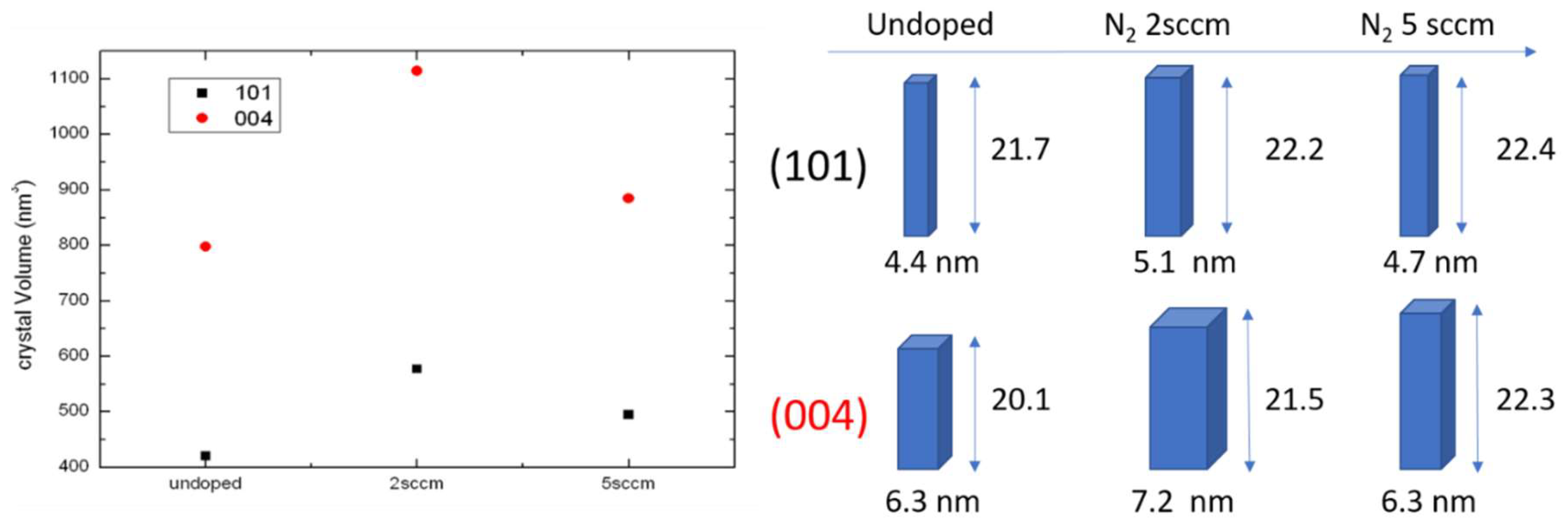
Grains size can be evaluated by applying the Debye–Scherrer calculation to the full width at half maximum (FWHM) of the diffraction peaks. The horizontal and vertical dimension of the nanograins can be also discriminated using different Bragg peaks acquired in symmetric and grazing geometries. The average nanodomain shape and sizes are represented in
Figure 2, right panel. In the left panel, we have chosen to represent the average domain volume for two different families of grains having the [101] and [001] growth directions perpendicular to the sample surface. Here, we found a second discontinuity in the volume of the nanograins that was larger in the layer grown using 2 sccm of N
2.
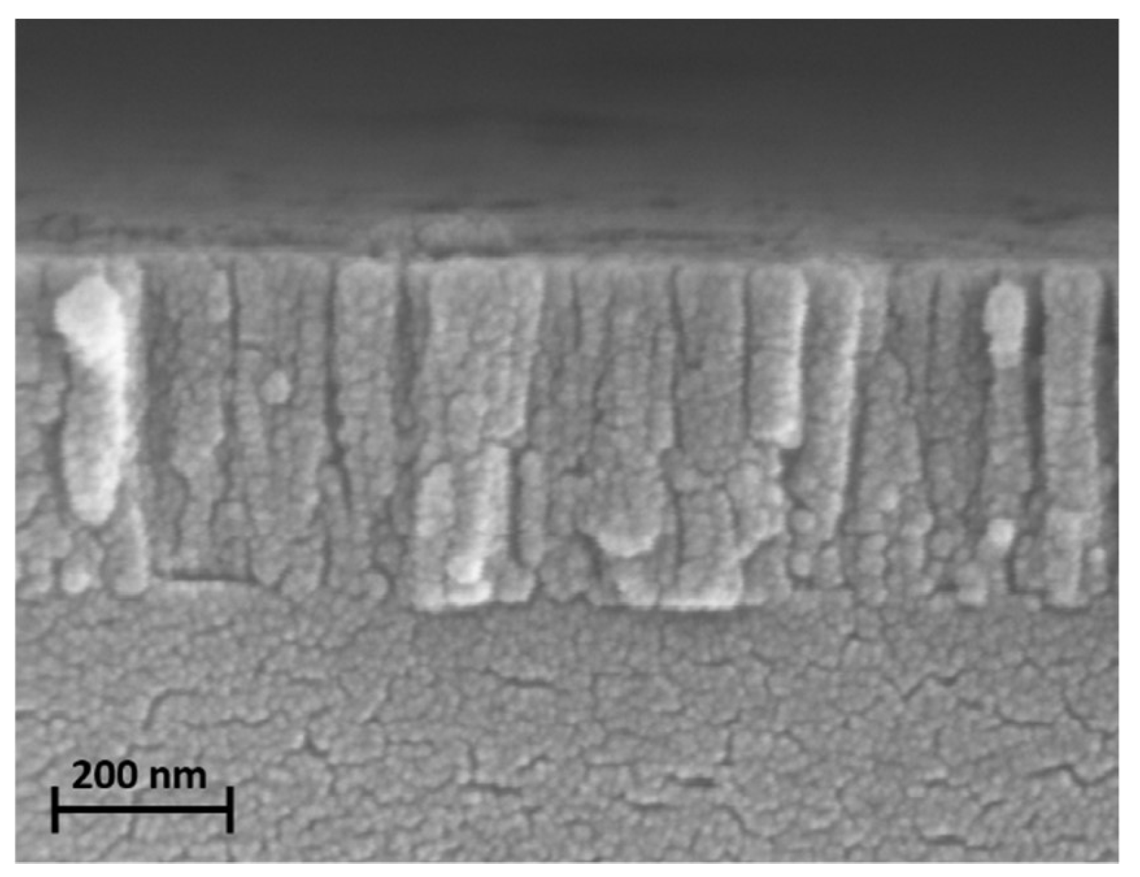
Figure 3 represents the described scenario by a representative SEM cross-sectional view of the material. An SEM image was taken in the as-deposited layer and, therefore, the nanostructuration was already a property of the material after deposition. According to this, and on the basis of our previous results [
11,
12,
13], we argue that annealing has the main role in promoting the atomic ordering inside the nanograins without inducing drastic modification of the nano/meso structuration of the layer.
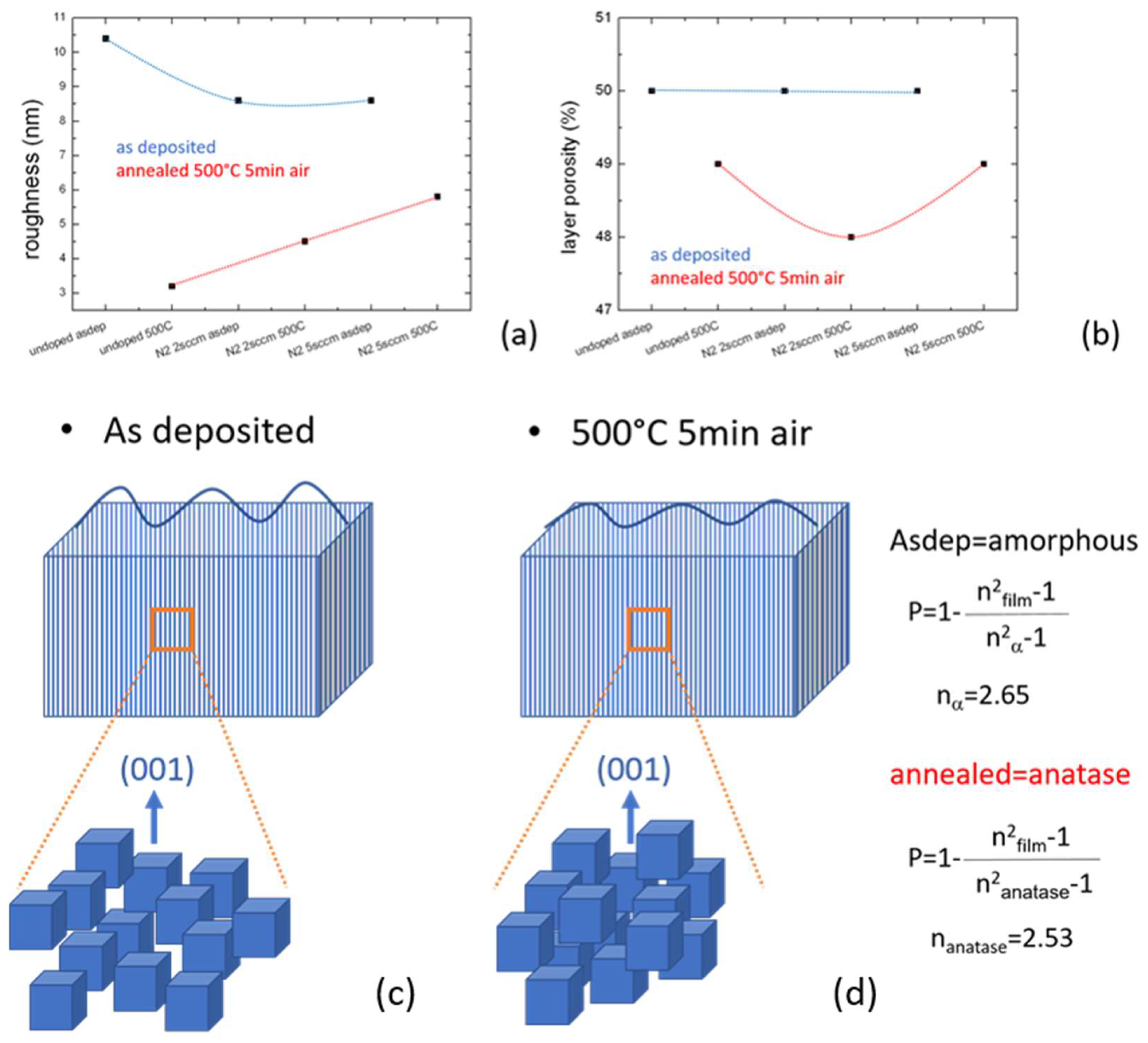
Roughness and porosity were evaluated by spectroscopic ellipsometry. They were slightly modified by the annealing, as shown in
Figure 4. The roughness of the layers decreased in all cases as well as the porosity that has been calculated using the formula in the inset of the same figure. This agrees with the behavior of undoped gig-lox layers, previously explored up to a thickness of 1000 nm [
13]. As a further fingerprint of the deposition at 2 sccm of N
2, we found a minimum value in the porosity curve after annealing. This could likely be linked to the morphology of the grains and their size. Intermediate cases are expected by annealing at temperatures <500 °C, as occurs when applying the material in a gas-sensing device [
13].
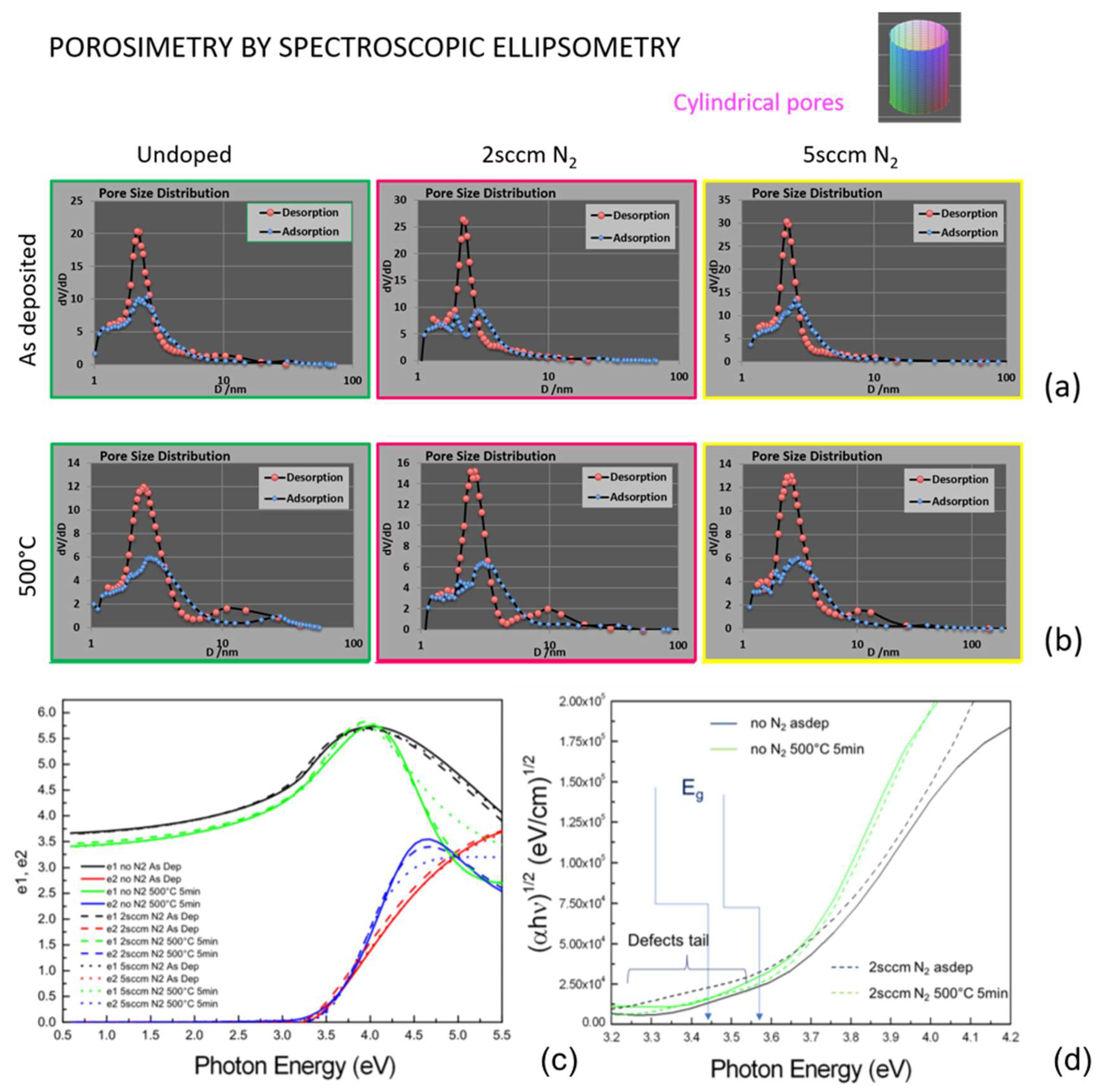
Environmental ellipsometry porosimetry was performed to estimate the pore dimension of the layers before and after the annealing. This parameter is crucial for the gas-sensing properties of the devices. The results of the analyses are shown in
Figure 5. The size distribution of the pores shows a main peak at around 4 nm for all the as-deposited layers. After the annealing, a slight broadening of the main peak and a better definition of a second band around 10 nm was recorded. All kinds of layers indeed exhibited a bimodality in the pore size distribution, as observed in our previous publication [
11]. This demonstrates that growing under nitrogen still allows for keeping the advantages of a double-size porosity. The annealing at 500 °C rearranged the structure in such a way that the nanopores’ size slightly spread out, framed in a better-defined mesopore array.
Non-ambient spectroscopic ellipsometry was used to explore the dielectric constant of the materials (
Figure 5a). According to what was observed in the structural findings, the annealing makes steeper e2 and shrinks e1 in all cases (the imaginary and real part of the dielectric constants, respectively). Main significant differences are highlighted by Tauc’s plot in
Figure 5b as follows: (a) Annealing the layer increased the bandgap in each kind of sample (including the one grown at 5 sccm not reported for simplicity); (b) the bandgap value was lowered by using N
2 during growth (e.g., from 3.44 eV to 3.57 eV in the 2s ccm N
2-grown sample); (c) differently from all the other samples, the TiO
2 layer grown under 2 sccm of nitrogen showed a long pre-gap tail, that is likely attributed to defects states into the gap [
8] introduced by the nitrogen doping.
XPS analyses were indeed performed to investigate the incorporation of nitrogen atoms into the TiO
2 matrix with details on the chemical surrounding and the configurational changes that occurred during annealing.
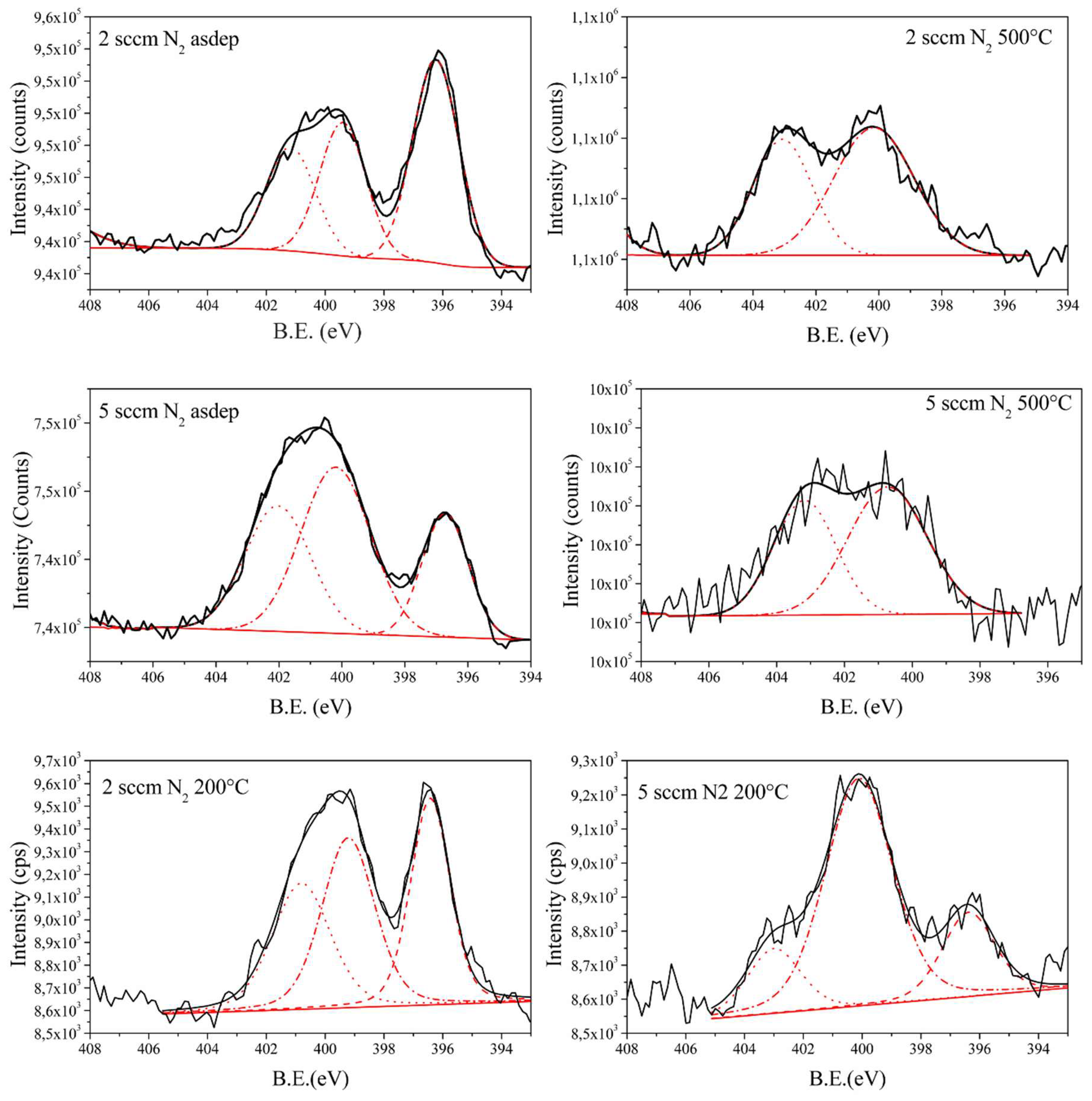
Figure 6 show the existence of the N1s band for all the samples analyzed. Results on the chemical analyses are summarized in
Table 2.
The large band around 400 eV in the as-deposited samples (
Figure 6) resulted from two different peaks—the first one centered at 399.7 eV is the peak related to nitrogen atoms in a TiO
2 matrix that could be related to nitrogen bonded with both titanium and oxygen atoms [
16], and the second one centered at ≈401 eV is related to nitrogen atoms in the organic form. The sample with the highest nitrogen content was the sample prepared with 2 sccm of N
2 with respect to the sample prepared at 5 sccm of N
2, despite the higher N
2 flow used during the deposition process. This result can be explained by competition established between Ti oxidation at the growing front and N
2–O
2 interaction inside the plasma region due to the particular geometry of the deposition chamber. The common inlet for the O
2 and N
2 gases is, in fact, located in the bottom part of the chamber, in close proximity to the substrate. At the lower N
2 intake, the reactive species are mostly confined above the substrate where they preferentially react with the titanium adatoms landing from the target. At higher fluxes, nitrogen species are evenly distributed inside the plasma, having an enhanced tendency to interact with oxygen into the plasma region. This likely promoted the formation of NO
x species and consequent reduction of the amount of nitrogen incorporated inside the film. Accordingly, the growth rate of the titanium oxide film reduces proportionally with increasing the flow rate of N
2 [
13].
As the main finding, the as-deposited samples (
Figure 6) showed a peak centered at 396.7 eV due to nitrogen atoms with nitride coordination [
17,
18,
19]. The presence of this peak testifies that nitrogen atoms introduced by the modified gig-lox process are positioned in the substitutional position in the crystal lattice. In this configuration, titanium atoms are positioned likely as in the TiN crystal lattice. The slight difference in the peak position with respect to the pure TiN films could be explained by the oxygen atoms as the second nearest atoms in the N–Ti–O [
17,
18] that are not present in the pure TiN material. The presence of the nitrogen atoms in substitutional position is also in agreement with the lower band gap (≈0.13 eV) and the long pre-gap tail found in the doped layers with respect to the pure TiO
2 films. The chemical analyses obtained from the high resolution spectra are reassumed on
Table 3.
We have additionally performed XPS analyses on annealed samples. After annealing at 500 °C, the nitrogen content decreased, and the peak related to the nitride fully disappeared in both samples (2 sccm and 5 sccm). We, instead, found a band centered at ≈404 eV due to nitrite form. During annealing, oxidation of the nitrogen atoms took place inside the film, with its partial desorption from the surface [
20]. The atomic percentage of nitrogen related to the peaks at ≈400 eV and ≈401 eV was the same after the annealing process. We speculate that the annealing process oxidizes the nitrogen atoms, initially coordinated inside the film as nitrides, due to their proximity with oxygen atoms. On the other hand, the nitrogen atoms in the organic form, which are adsorbed on the surface, are not affected by the oxidation during annealing.
A different scenario was found on samples annealed at 200 °C. This temperature was chosen since it is close to typical working temperatures for sensing (a proof of concept will be given hereafter). After annealing at 200 °C, substitutional nitrogen species, although in an amount slightly decreased, still persisted as the dopant in the sample deposited at 2 sccm of N2 (peak at 396.7 eV).
4. Application for Ethanol Sensing
As proof of concept, the layer grown at 2 sccm of nitrogen was indeed integrated into a state-of-the-art micro-hot-plate technology (
Figure 7) as done in Reference [
13]. The material integration was easily done as the last production step without requiring lithographic or etching processes. The gig-lox doped layer was directly deposited on the exposed area of the micro-hot-plate at room temperature, and this allowed for the preservation of all the pre-existing materials into the device. The sensor showed a better response than the one based on the oxide grown using 5 sccm of N
2 due to the higher nitrogen doping [
21,
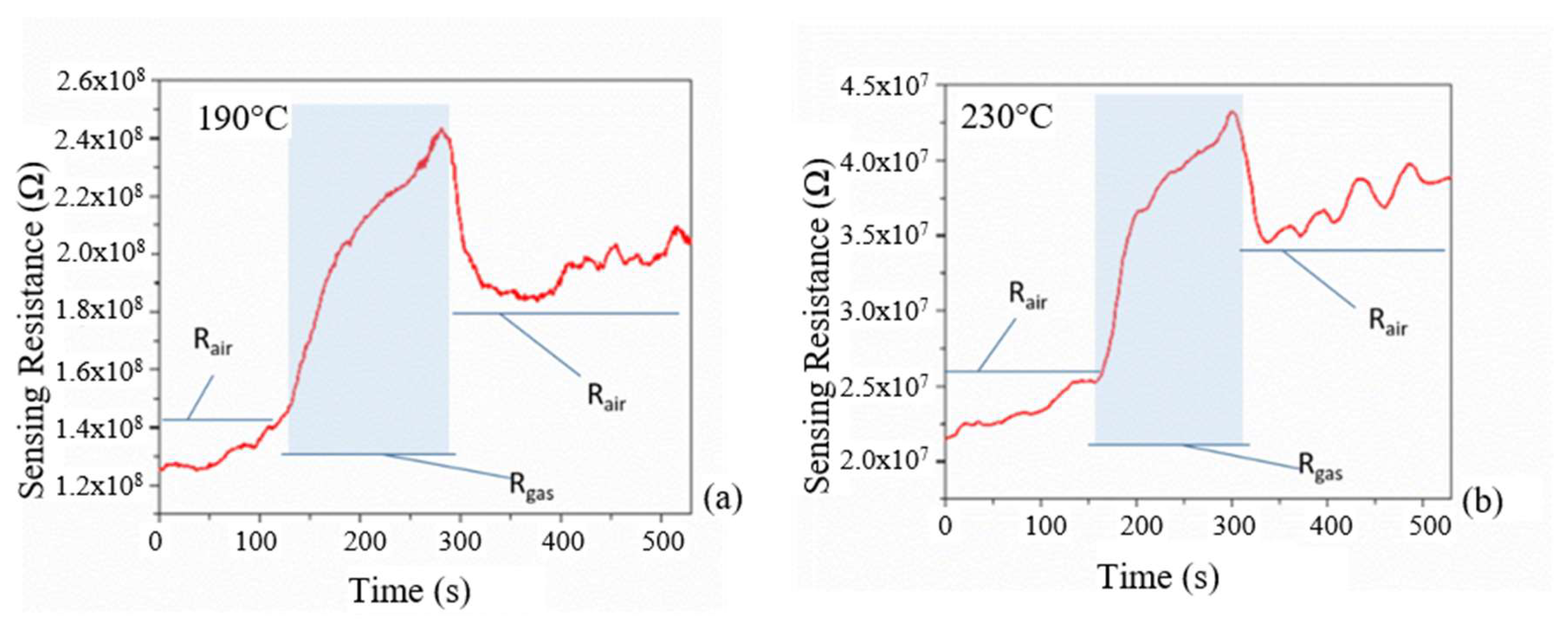
22]. The results are shown in
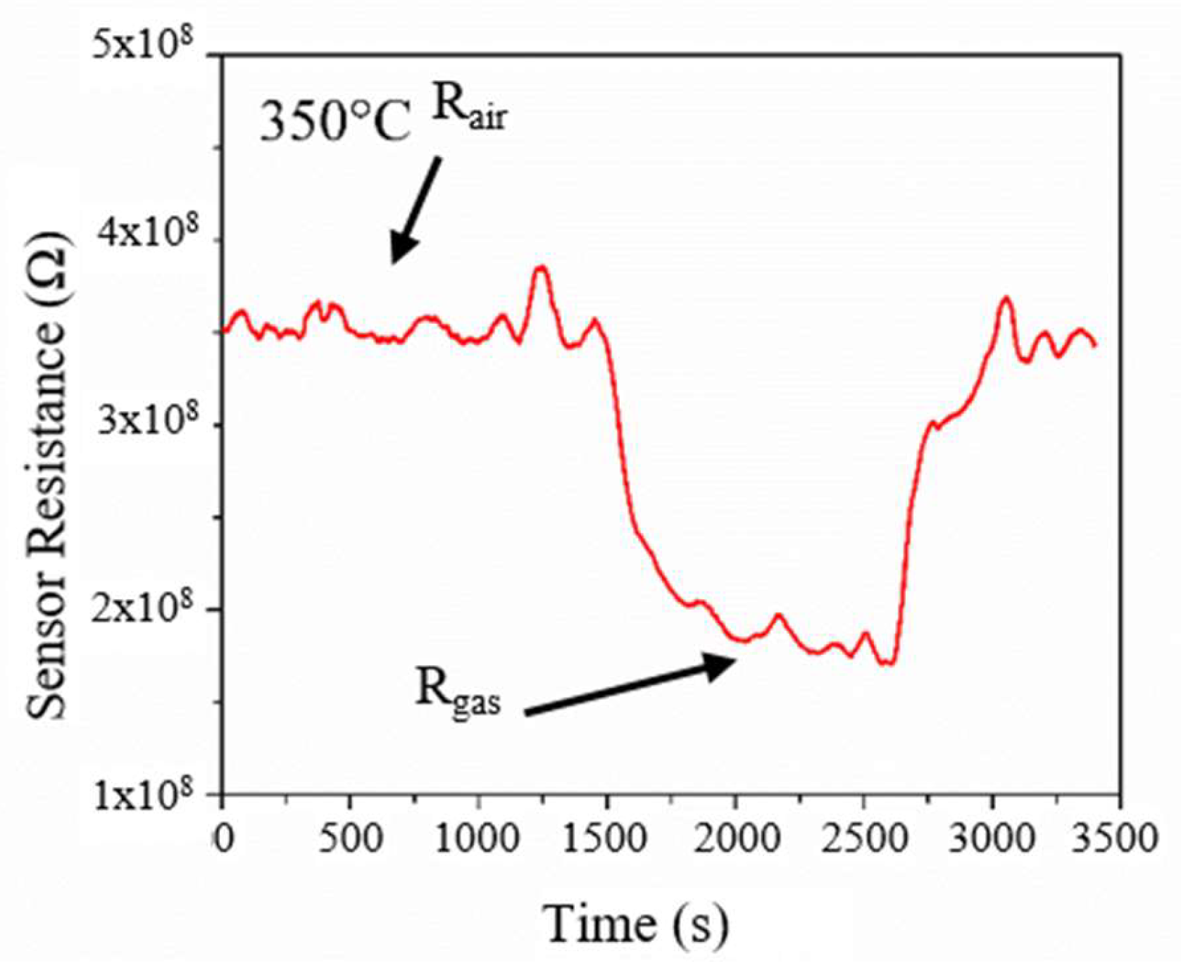
Figure 8, in which the p-type responses, for the doped sample at two different temperatures (190 °C and 230 °C), are shown when 44 ppm of ethanol was made to flow through the reaction chamber, in dry condition. The R
air is the resistance measured when only air is in the chamber, while R
gas is the resistance measured when ethanol gas is introduced inside the chamber.”
The Rair progressively increased at 190 °C and 230 °C likely due to a structural modification of the deposited film (increasing of the baseline). When the ethanol gas was introduced inside the chamber, the resistivity of the sensing layer increased, with a response time of about 10 s (step-up in the resistivity), and decreased with a comparable response time of about 10 s when the ethanol gas flow was switched off (step back of the resistivity). After the ethanol flow was switched off, the resistivity value did not get back to the initial value. We argue that, during the test, the temperature promoted a rearrangement of the initial crystal lattice towards the formation of the anatase phase, as seen by our structural results. In this respect, a stabilization process must be framed into the production steps of the sensor for production.
A drastic change of the sensor response was obtained keeping the device at a working temperature of 350 °C for 240 min. As shown by XPS analyses, the nitrogen atoms were initially located in a substitutional position inside the film. This created a level inside the band gap above the valence band of the pure TiO
2 giving the p-type character [
21]. The annealing reset this doping condition in short laps of time as demonstrated by XPS analyses. An intermediate case was found by annealing at 350 °C since 240 min were needed to complete nitrogen release and to observe the change in the sensor behavior from p-type to n-type.
After this in situ annealing, the sensor turned to an n-type response, characterized by a decrease in the resistance of the material according to the well-established surface-depletion model (
Figure 9). The evaluation on the responsivity, figured by the formula: (R
air − R
gas)/R
air × 100, after injection of 44 ppm of ethanol in a dry condition and working temperature of 350 °C, provided a sensing response of 51.4 ± 0.1%. The sensor detection limit was 10 ppm. We chose to explore the gas sensor capability of the material in a concentration range that provided a clear response, remaining low enough for potential applications in the detection of main hazardous volatile species. The experiment allowed for the definition of a process window for a working response of the N-doped gig-lox TiO
2 sponge in the range 200–350 °C.
5. Conclusions
P-type nitrogen doping through modified gig-lox methodologies is feasible even at room temperature. The doping procedure does not penalize the multibranched nature of gig-lox oxides. Doping was performed at room temperature and was maintained up to 350 °C during ex-situ annealing. Further raising of the temperature was inconvenient for the doping as well as for the porosity preservation.
As a drawback, nitrogen introduced as reactive gas reduced the deposition rate of the TiO2 layer mainly due to competing N–O reactions through the plasma region. The optimal doping was obtained using 2 sccm of nitrogen, although the surface-to-volume ratio was in favor of the layer deposited at 5 sccm. This is due to properly incorporated nitrogen atoms that were mainly positioned in a substitutional position with respect to the oxygen in the TiO2 lattice at the low N2 flow rate, giving the layer a clear p-type character. Accordingly, the sensor exhibited a p-type response to ethanol species with the resistance rising by a factor 2 at ≈200 °C under operation. In the range of 350–500 °C, the sensor turned to n-type as the ones made of undoped TiO2 films. The phenomenon was related to a loss of the nitrogen content inside the film during the annealing. Low-temperature operation and a stabilizing procedure before operation are featured by our experiment that would render the sensor applicable on flexibles substrates. Sensitivity to other gas species with similar, or even superior, surface reactivity as the ethanol species is addressed and can be explored in future works.
The integration of the N-doped gig-lox TiO2 sponge at room temperature on a sensing device is simple and can be done as the last production step. Thin layers are required for sensing (~400 nm), and working temperatures are low. Easy TiO2 doping procedures, combined with porosity, are of general purpose and interest for several applications.

 ,
, 


