Study on Ultrasonic Assisted Electrochemical Drill-Grinding of Superalloy


1
School of Mechanical, Electrical & Information Engineering, Shandong University, Weihai 264209, China
2
College of Mechanical and Electrical Engineering, Nanjing University of Aeronautics and Astronautics, Nanjing 210016, China
*
Author to whom correspondence should be addressed.
Chemosensors 2020, 8(3), 62; https://0-doi-org.brum.beds.ac.uk/10.3390/chemosensors8030062
Submission received: 30 June 2020
/
Revised: 29 July 2020
/
Accepted: 30 July 2020
/
Published: 3 August 2020
(This article belongs to the Section Electrochemical Devices and Sensors)
Abstract
:Electrochemical grinding (ECG) technique composed of electrochemical machining (ECM) and mechanical grinding is a proper method for machining of difficult-to-cut alloys. This paper presents a new ultrasonic assisted electrochemical drill-grinding (UAECDG) technique which combines electrochemical drilling, mechanical grinding, and ultrasonic vibration to fabricating high-quality small holes on superalloy. By applying ultrasonic vibration to high-speed rotating electrode in ECG, machining stability, efficiency, and surface quality can be obviously improved. Firstly, the electrochemical passive behavior of superalloy is studied, the mathematical model and simulation of gap electric field are established. Then, several experiments are conducted to investigate the influence of applied voltage, feed rate and ultrasonic amplitude on the machining quality. The balance of material removal between electrochemical reaction and mechanical grinding is achieved by optimizing the machining parameters. It reveals that the surface quality as well as machining stability and efficiency can be significantly improved by applying rotating ultrasonic vibration to the ECG process. Finally, several small holes of high quality have been machined successfully along with surface roughness of hole sidewall decreases from Ra 0.99 μm to Ra 0.14 μm by UAECDG.
1. Introduction
Nickel-based superalloys have been widely used in heated end components of aviation and aerospace engineering with advantages of high strength and toughness in elevated temperature, good oxidation resistance, excellent thermal stability, and fatigue properties [1,2,3]. However, nickel-based superalloys are hard to machine due to the low thermal conductivity and high temperature strength [4,5], which could cause poor surface quality, serious tool wear, and low productivity in traditional machining [6,7,8]. As for a few non-traditional machining methods, laser machining [9,10] and electrical discharge machining (EDM) [11,12] which based on heat melting usually produce micro cracks, recast layers, and heat affected zones, while electrochemical machining (ECM) [13] could not meet the demands of high precision machining due to stray current corrosion.
Electrochemical grinding (ECG) is a compound machining technique composed of ECM and mechanical grinding. During the ECG process, a kind of soft passive oxide film is generated on the surface of metal materials with electrochemical reaction, and then be removed by abrasive erosion immediately so that the inside metal materials can bear out for the consecutive electrochemical dissolution [14,15]. Generally, the mechanical grinding in ECG is only used to scrape the passive oxide film generated on the surface of metal rather than metal materials itself, and about 5–10% of machining takes place with the assistance of abrasive action [16]. Due to the passive oxide film being much softer than metal materials, the machining efficiency is significantly increased and tool wear is avoided effectively compared with traditional grinding, especially for dealing with nickel-based superalloys and other difficult-to-cut alloys [17]. In addition, benefiting from employing mechanical grinding, ECG can obtain a better machining precision and lower surface roughness compared with the conventional ECM [18].
In the past few years, many studies on ECG have been done. P. Ming et al. carried out a diamond mounted point ECG method for removing a recast layer produced by EDM and investigated the effects of applied voltage, electrolyte, tool rotating speed, and cut depth on surface roughness [19]. D.T. Curtis et al. employed ECG with fixed abrasive to cut nickel-based superalloys and discussed the influence of abrasive grit type and electrical parameters on roughness and overcut [16]. D. Zhu et al. proposed an electrochemical drill-grinding method for precision machining of small holes and found that the balance of ECM and mechanical grinding in ECG was the key to improve machining precision and surface quality [20]. N. Qu et al. found that the tool durability could be extended more than three times by substituting brazed diamond wheel for electrodeposited diamond wheel in ECG and the material removal rate could be significantly promoted by employing optimized voltage and electrolyte temperature [21]. K. Przystupa et al. applied ECG to the machining of titanium alloys and investigated the micro short circuit in ECG [22]. H. Li et al. proposed an electrochemical mill-grinding (ECMG) with inner-jet method to machine flow channel structure of GH4169 superalloy, and carried out the simulation analysis of the flow and electric field in ECMG process [18,23,24]. S. Niu et al. designed a series of tool electrodes with tool-sidewall outlet holes and bottom insulated for ECMG, and the experiments revealed that the flatness of sidewall was ameliorated by using a tool electrode with spiral arrangement of outlet holes and the flatness of the bottom was improved by applying a tool electrode with bottom insulated [25,26]. Y. Ge et al. put forward an electrochemical deep grinding technique and analyzed material removal phenomenon in electrochemical deep grinding. They proposed that it was electrolytic products, but not compact passive film, that adhered to the machined surface during electrochemical deep grinding process [27]. X. Zhu et al. applied ultrasonic vibration in ECG for the fabrication of small holes on 304 stainless steel and found that the machining accuracy and surface quality of small holes were effectively improved by ECG with reasonable ultrasonic vibration [28]. At present, although ECG has shown great advantages on machining of difficult-to-cut alloys, it is still confronted with problems such as instability of machining process and inhomogeneity of flow and electric field, particularly for fabrication of small holes.
Due to the mass electrolysis products and small machining gap in ECG of small holes, it is difficult to keep stability in ECG process and even cause a short circuit, which will cause low efficiency, poor surface quality, and excessive tool wear [20,22]. This paper presents an ultrasonic assisted electrochemical drill-grinding (UAECDG) method in which rotating ultrasonic vibration is employed with ECG for the fabrication of small holes with efficiency and precision. In this paper, an UAECDG experimental set-up is established and a ball-end abrasive electrode is designed as tool cathode. The electrochemical behavior of GH3030 superalloy in different electrolyte environments is studied. Based on the research of electrochemical behavior, the mathematical model and electric field simulation of machining gap are established. In addition, a serious of comparative experiment are carried out to discuss the effect of different machining parameters on machining efficiency and surface quality. Finally, small holes with high quality are machined successfully by optimized machining parameters.
2. Experimental Set-Up and Machining Process Analysis
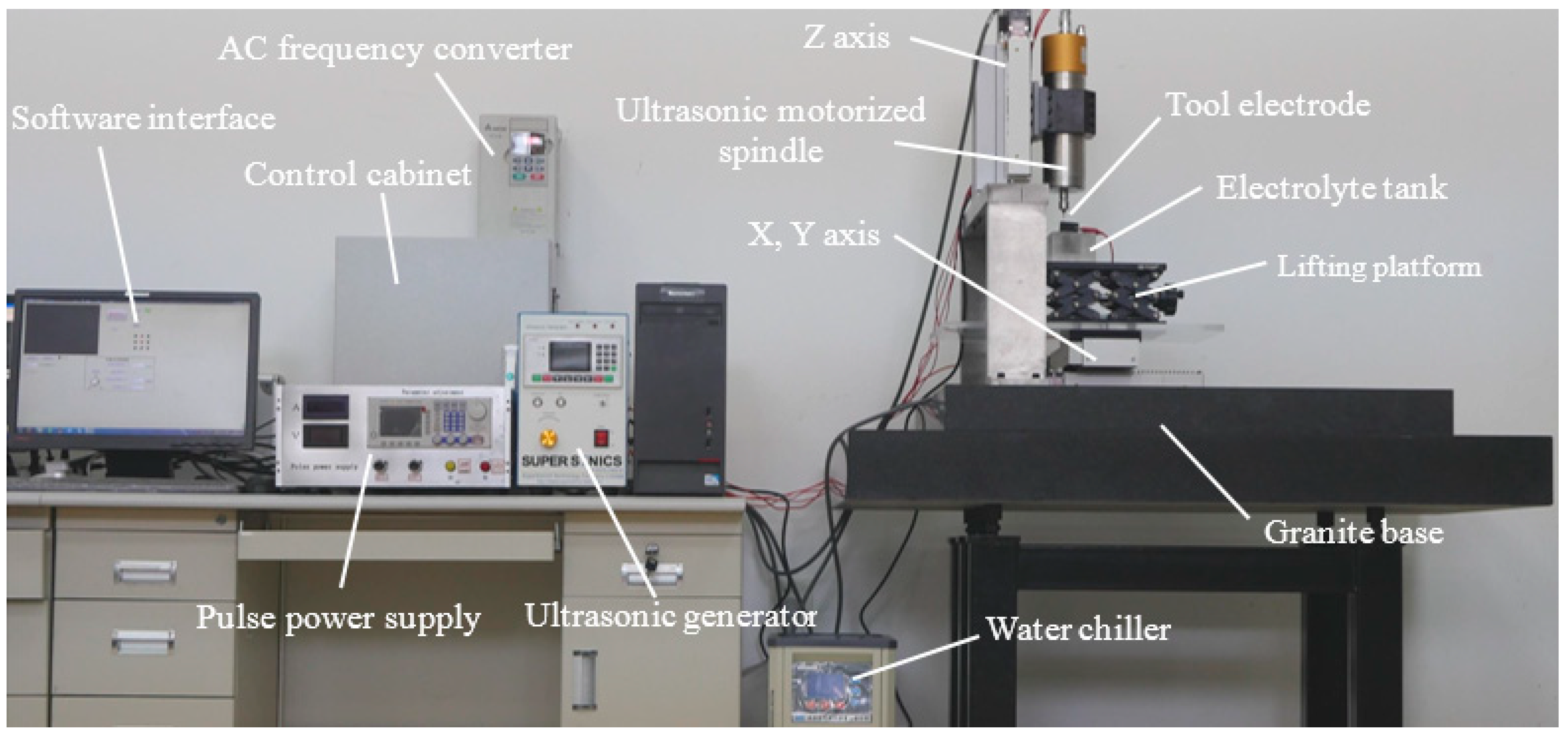
The experimental system with high precision for UAECDG is constructed as shown in Figure 1. This experimental system is mainly composed of a three-axis machine tool, ultrasonic generator, ultrasonic motorized spindle, pulse power supply, DC power supply, electrode component, electrolyte recycle device, monitoring, and data acquisition module.
The motions of the three-axis machine tool have a resolution of 0.1 µm, which satisfies the requirement of UAECDG. Driven by the ultrasonic motorized spindle, the tool electrode can ultrasonically vibrate along the z-axis direction and rotate at high speed. The ultrasonic vibration applied to the tool electrode has a maximum amplitude of 13 µm along and a frequency of 20–35 kHz. The maximum rotation rate of the spindle is 24,000 r/min which satisfies the experiments. The monitoring and data acquisition modules which used to observe the phenomena and monitor the voltage and current signals in UAECDG consist of ammeter, oscilloscope, CCD vision monitor, and date acquisition card.
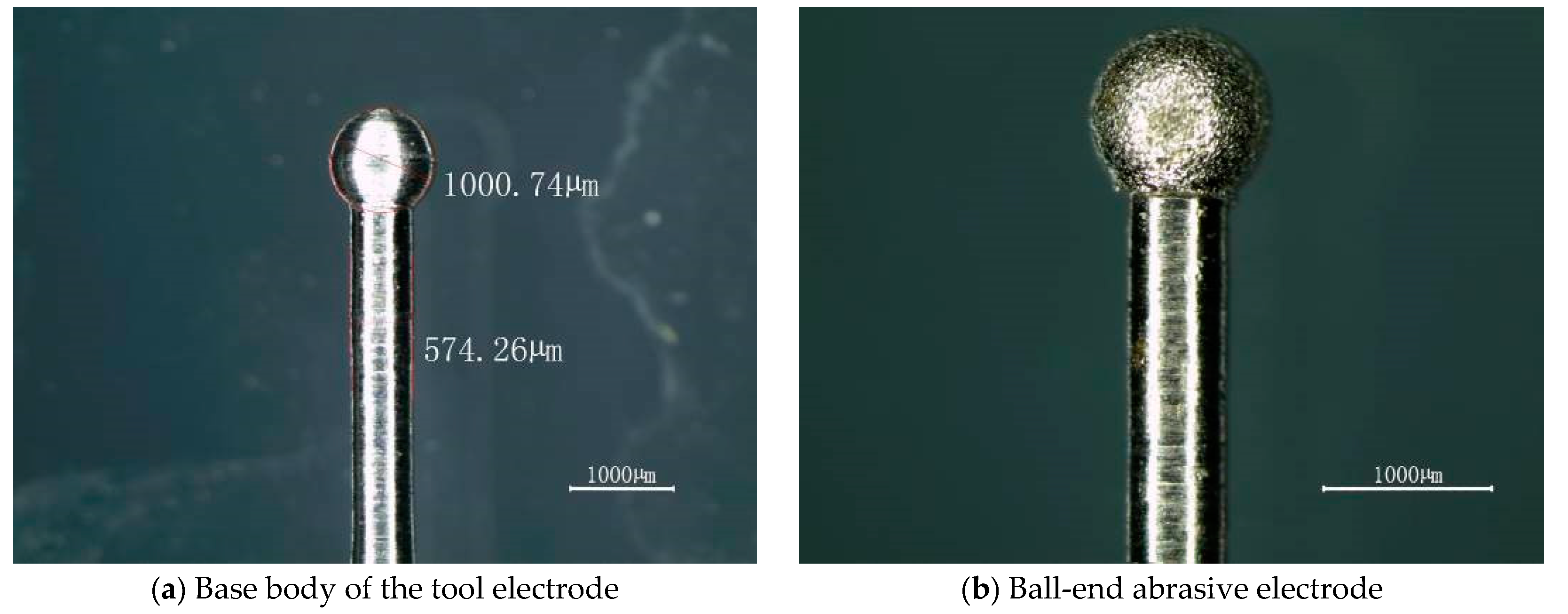
The electrode component includes the tool holder, flexible conductive device, workpiece and the tool electrode. As an important part of the experimental set-up, the shape and size of electrode directly determine the machining precision and the surface quality. Figure 2 shows a ball-end abrasive electrode fabricated by electrodeposition is designed as tool cathode. The diamond particles range in size from 12 µm to 15 µm are bonded to the base body by nickel coating, and about 60–65% size of diamond particles is exposed. The base body of the tool electrode and nickel coating are electroconductive whereas abrasive particles are electrically non-conductive so that the electrochemical reaction and mechanical grinding can operate at the same time.
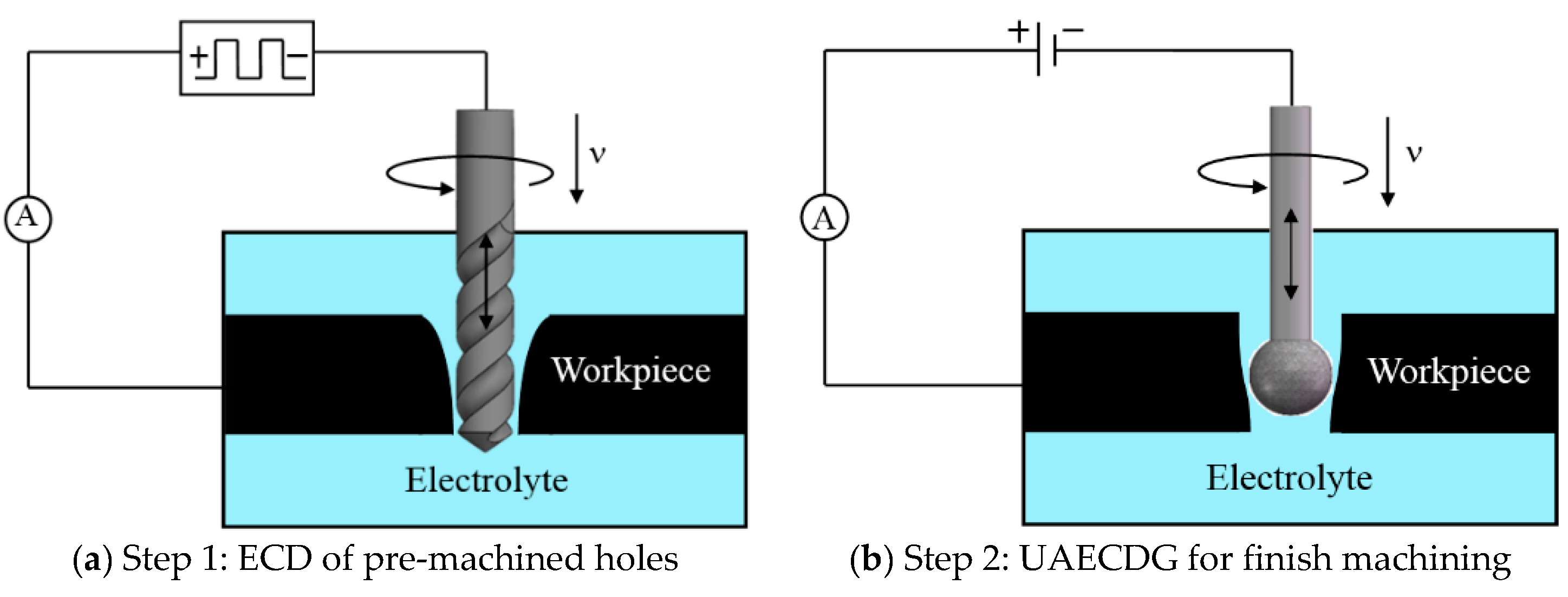
In this paper, a complete process of fabricating small holes includes two steps. Step 1 is a process of electrochemical drilling (ECD) of pre-machined holes by using a helix electrode as shown in Figure 3a, step 2 is a process of UAECDG for finish machining of small holes by using a ball-end abrasive electrode as shown in Figure 3b. Both steps are conducted in one experimental set-up. In step 1, an ultra-short pulse voltage and helix electrode with high rotating speed are employed in ECD to fabricate pre-machined holes with high machining precision. Then, to avoid positional error, tool changing without repositioning is carried out after accomplishing the machining of pre-machined holes. In step 2, the UAECDG technique and passive electrolyte are employed for the finish machining of small holes.
In UAECDG, the anode is a workpiece and the cathode is ball-end abrasive electrode. The ball-end diameter should be slightly larger than the pre-machined hole for machining. Because of the passive behavior of GH3030 superalloy, in passive electrolyte, it is easy to generate a passive oxide film adhering to the workpiece surface, which is adverse to electrochemical dissolution. The passive oxide film will be immediately removed by abrasive erosion so that the inside metal materials can bear out for the consecutive electrochemical dissolution. On the other hand, the ultrasonic vibration of the electrode contributes to electrolyte update and the transport of hydrogen bubbles and other electrolysis products, and thus to the uniformity of flow field. In this way, the machining stability and efficiency can be significantly improved compared with the conventional ECG.
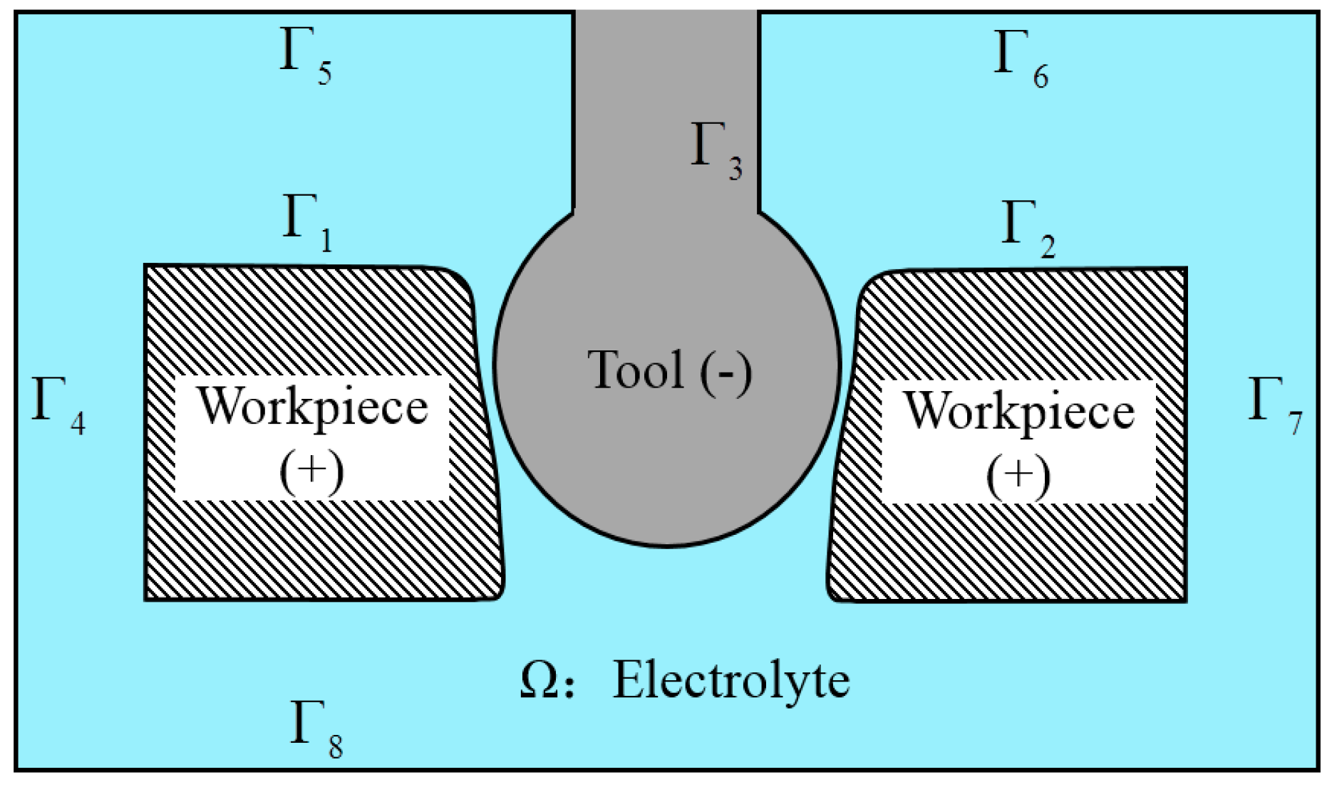
The material removal in ECG mainly depends on electrochemical reaction, about 90–95% of the workpiece material is removed by ECM in general [16]. Owing to the secondary electrolysis, it is hard to avoid hole taper in ECD [29]. To reduce the hole taper caused by secondary electrolysis, this paper proposed an abrasive electrode with a ball-end as tool cathode in UAECDG. A simulation is carried out to describe the current density distribution and electrochemical dissolution with machining process based on the assumption that the conductivity of electrolyte is constant. Figure 4 schematically depicts the diagram of the gap electric field in the process, and Table 1 shows the parameters applied in the simulation. The potential distribution of the electrolyte region satisfies Laplace equation.
where is electric potential, and is the electrolyte region. The boundaries of anode as well as cathode accord with Dirichlet boundary condition and the rest boundaries accord with Neumann boundary condition.
where is the applied voltage, and are the boundaries of workpiece, is the boundary of tool, – are the boundaries of electrolyte, and is the unit normal vector to the surface.
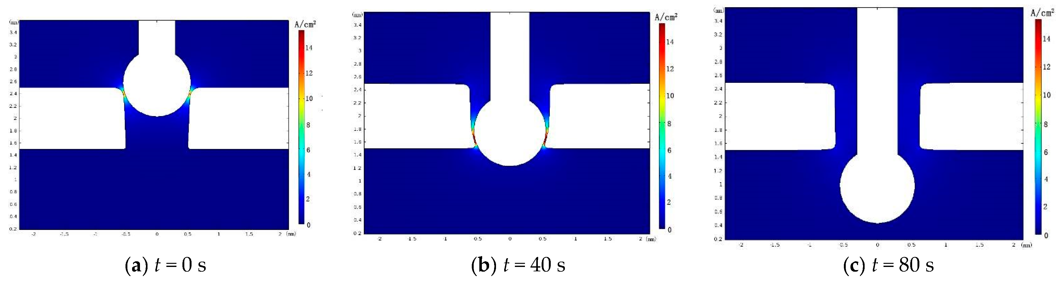
Figure 5 shows the electric field simulation of UAECDG. The large current density only appears around the ball-end so that the electrochemical reaction is restricted to the domain around the ball-end, which can reduce the influence of secondary electrolysis and improve the machining localization. In this way, with feeding down of tool electrode, the hole taper can be obviously reduced by limiting the electrochemical reaction to the zone near the ball-end of the electrode.
3. Material and Mathematical Model
3.1. Electrochemical Behavior of Materials
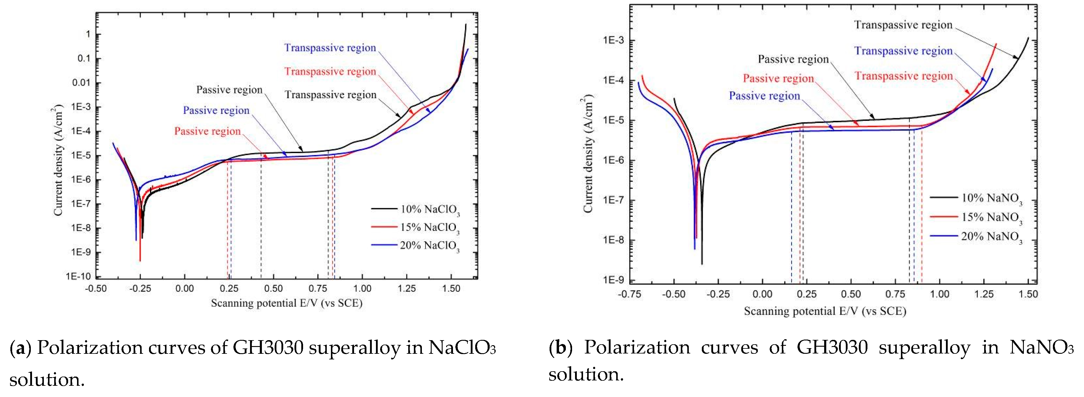
As a kind of nickel-based superalloy, GH3030 superalloy shows passivity in several passive solutions, for instance, NaNO3 solution and NaClO3 solution. When materials perform passive behavior, there is a passive oxide film generated adhering the surface of materials with electrochemical dissolution. This passive oxide film which counteractive at electrochemical reaction is a link between the ECM and abrasive grinding. It is indicated that the compact oxide film can protect materials surface from stray-current corrosion [30]. Additionally, the surface of the material becomes smooth and glossy after the electrochemical dissolution under the condition of passivation. Therefore, it is essential to investigate the electrochemical behavior of GH3030 superalloy in different electrolyte environments. Figure 6 shows the polarization curves of GH3030 superalloy in different passive electrolyte environments.
NaClO3 solution and NaNO3 solution are typical passive solutions. As shown in Figure 6, the polarization curves of GH3030 superalloy in NaClO3 solution as well as NaNO3 solution are characterized by active dissolution, passivation, and trans passivation. Within the passive region, the passive oxide film has been generated on the surface of metal material and the current density relatively remains constant. Figure 6a shows the polarization curves of GH3030 superalloy in 10–20% NaClO3 solutions. It is obvious that the passive potential ranges of GH3030 superalloy in 15% and 20% NaClO3 solutions are wider, meaning that the stable passivation is more likely to occur on the surface of GH3030 superalloy in 15% and 20% NaClO3 solutions. GH3030 superalloy has a passive potential range of 0.24 to 0.83 V in 15% NaClO3 solution and 0.26 to 0.84 V in 20% NaClO3 solution.
Figure 6b shows the polarization curves of GH3030 superalloy in 10–20% NaNO3 solutions. The passive potential ranges of GH3030 superalloy in 10–20% NaNO3 solutions are similar. However, with GH3030 superalloy in 15% and 20% NaNO3 solutions, the current density during the passive regions has less change with scanning potential, meaning that a more compact passive oxide film can be formed on the surface of GH3030 superalloy. The passive potential range of GH3030 superalloy is from 0.20 to 0.90 V in 15% NaNO3 solution and from 0.16 to 0.85 V in 20% NaNO3 solution.
By comparing the polarization curves of GH3030 superalloy in the NaClO3 solution and NaNO3 solution, it can be found that the passive potential range of GH3030 superalloy in NaNO3 solution is wider and the passive current density of GH3030 superalloy in 20% NaNO3 solution is lower, which means the stable passive oxide film is more easily generated on the surface of GH3030 superalloy in 20% NaNO3 solution. Therefore, this paper employs 20% NaNO3 solution as the electrolyte in UAECDG.
3.2. Mathematical Model
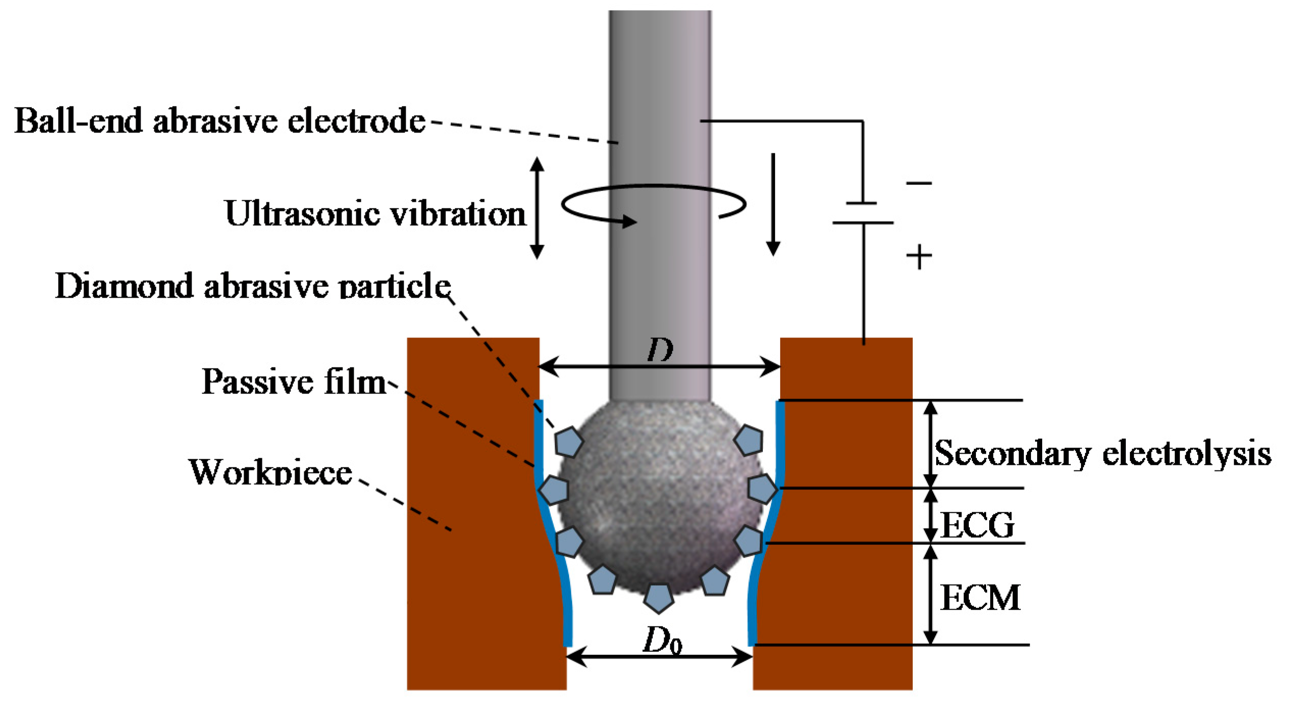
Figure 7 shows the schematic diagram of UAECDG. The diameter of pre-machined hole is slightly smaller than the diameter of the ball-end. The materials removal in UAECDG is determined by a compound machining process composed of ECM and mechanical machining. The machining gap of UAECDG can be divided into ECM stage, ECG stage, and secondary electrolysis stage. Only in the ECG stage, abrasive particle can remove the remove the passive oxide film which adverse to ECM, so that the most materials removal appears at the stage of ECG.
Figure 8 schematically depicts the diagram of machining gap in UAECDG. It can be assumed that the phase of ECG begins from point Q. The position of Q is mainly determined by the diameter of pre-machined hole, the diameter of ball-end, tool feed rate, and applied voltage. When the process of UAECDG at a stable state, the machining gap S0 at point Q can be approximately expressed as:
where is average machining gap, is ultrasonic amplitude, is ultrasonic period, is machining time and is related with the position of point . The rate of electrochemical reaction at point is expressed as
where is feed rate of the tool electrode, is current efficiency, is electrochemical equivalent volume of anode material, is electrical conductivity of the electrolyte, and is decomposition potential of anode material, the stable overpotential is approximately expressed as
where is applied voltage, is machining current, is resistance of electrolyte and is resistance of the passive oxide film.
According to (5) and (6), can be obtained as
During the phase of ECG, the relationship between the average machining gap and machining time can be expressed as
Equation (9) can be integrated as
At the initial time of the ECG, while . Thus
Because material removal mainly occurs in ECG phase, it can be assumed that the hole diameter is determined by the phase of ECG. Thus, the final machining gap can be approximately expressed as
where is ball-end diameter. The stable overpotential has been given in (7), and the initial machining gap has been given in (8). Therefore, the hole diameter after UAECDG can be expressed as
As shown in Equation (13), when the other machining conditions remain constant, the hole diameter increases with diameter of the ball-end, applied voltage and electrical conductivity of electrolyte but decreases with feed rate of tool electrode as well as the resistance of passive oxide film and electrolyte.
4. Experimental Results and Discussion
As the structures to be machined, the pre-machined holes directly determine the machining gap and cut depth in UAECDG. To ensure the diameter of the pre-machined holes constant, the pre-machined holes with high repeat machining precision are fabricated by ECD before the process of UAECDG. To maximize ultrasound energy, the output frequency of ultrasonic vibration is locked at the natural frequency of the tool electrode. Table 2 shows the parameters applied in the experiments.
4.1. Influence of Ultrasonic Amplitude
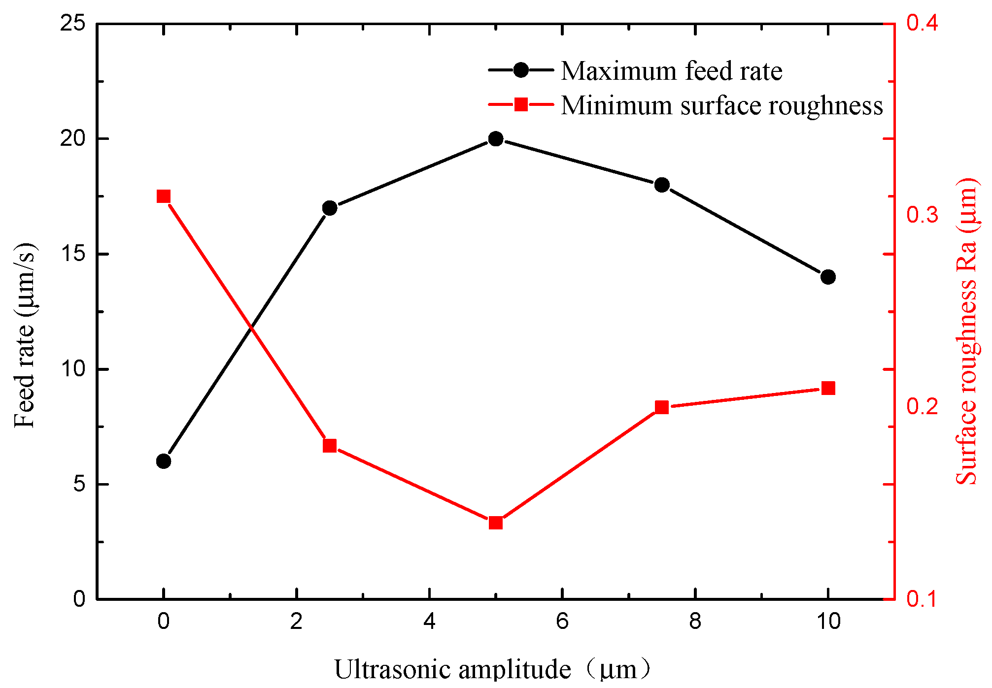
The tool electrode with ultrasonic vibration has a stirring effect on the electrolyte. To investigate the influence of ultrasonic amplitude on efficiency and surface quality, several experiments are carried out with constant voltage of 6 V and ultrasonic frequency of 25 kHz. Figure 9 shows the influence of ultrasonic amplitude on maximum feed rate and minimum surface roughness.
It is indicated from Figure 9 that the maximum feed rate allowed of electrode is significantly improved from 6 μm/s to 20 μm/s with ultrasonic amplitude from 0 to 5 μm. It is because the ultrasonic vibrating of the electrode is instrumental in the refreshment of electrolyte and the transport of heat, hydrogen bubbles, and other electrolysis products so that the electrochemical reactions are promoted. On the other hand, from Equations (8) and (11), the average machining gap increases with ultrasonic amplitude. The material removal rate of electrochemical reaction decreases with the average machining gap so that maximum feed rate is limited by the electrochemical reaction, which means that the maximum feed rate tends to decrease when ultrasonic amplitude is further than 5 μm.
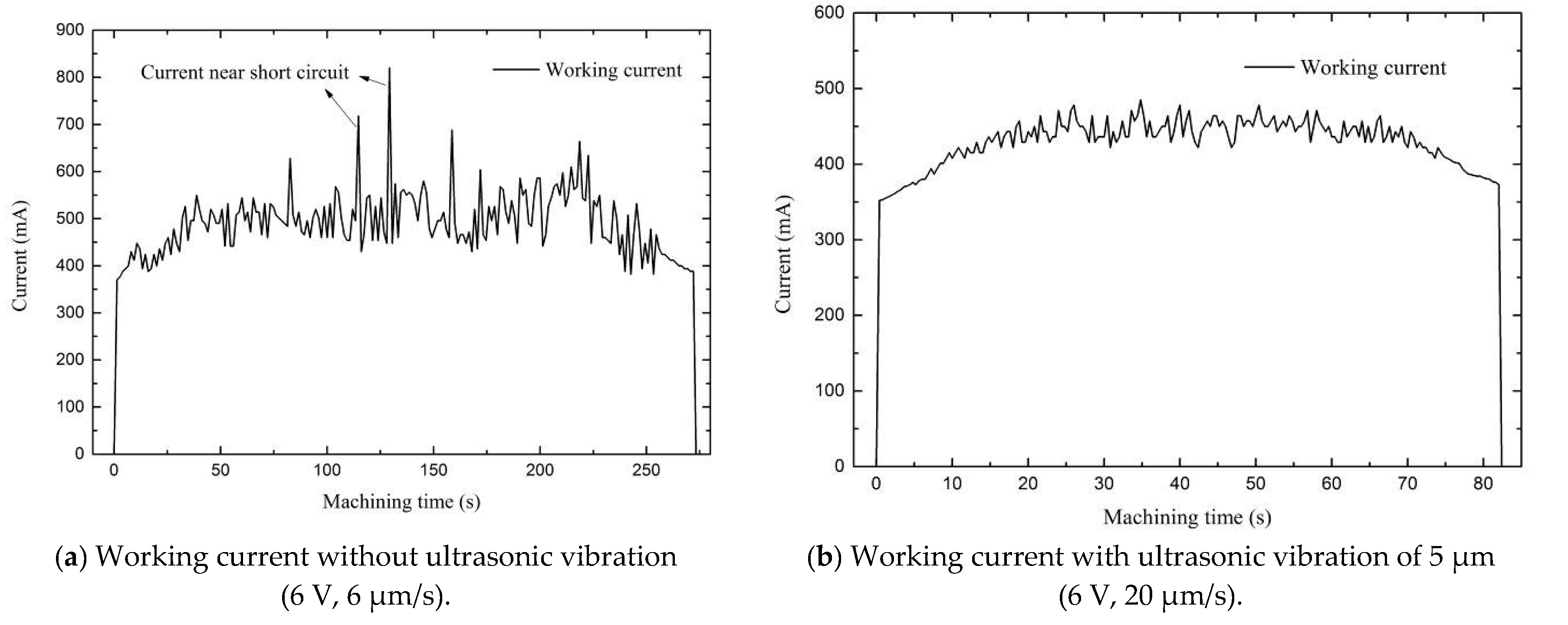
In addition, it is indicated from Figure 9 that the surface roughness decreases obviously by applying ultrasonic vibration to tool electrode. It is because the tool electrode with ultrasonic vibration can promote removing of electrolysis products and refreshment of the electrolyte in machining gap, which makes the flow field more uniform and improves the machining stability. Figure 10 shows the current signals in UAECDG with and without applying ultrasonic vibration on tool electrode. As shown in Figure 10a, the machining process without ultrasonic vibration applied is not stable enough because of the small machining gap and difficulty in taking away the electrolysis products in time. When ultrasonic vibration is applied to the tool electrode, the working current is more stable and a short circuit can be effectively avoided as shown in Figure 10b, therefore the holes with low surface roughness Ra can be obtained.
4.2. Influence of Ultrasonic Amplitude Influence of Applied Voltage and Feed Rate
In UAECDG, it is essential to keep a proper and stable machining gap. The balance of material removal between ECM and mechanical grinding is the key to obtain high precision and surface quality. ECM is mainly determined by applied voltage while the mechanical grinding is mainly influenced by feed rate. Therefore, the machining stability can be controlled by the applied voltage and feed rate. Several experiments are conducted to investigate the influence of applied voltage and feed rate on hole diameter and surface quality with constant ultrasonic amplitude of 5 μm.
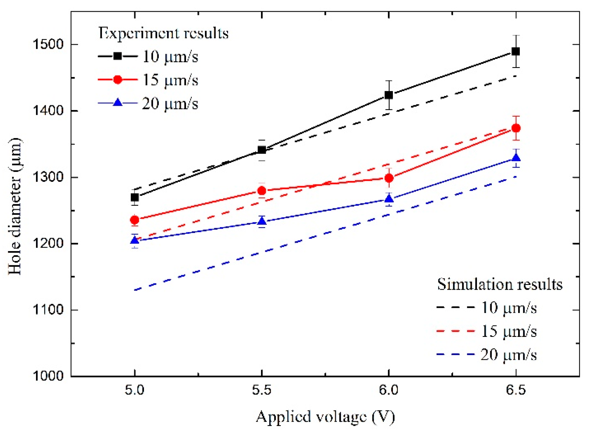
Figure 11 shows the impact of voltage and feed rate on hole diameter by simulation and experiments. Both simulation and experiments indicate that the hole diameter increases with applied voltage but decreases with feed rate, which is according with Equation (13). When the feed rate is constant, the higher applied voltage, the higher current density in the machining, and the ability of the electrochemical reaction is stronger to remove the materials so that the hole diameter is larger. On the contrary, when the applied voltage is constant, the machining time of the electrochemical reaction decreases with the feed rate so that the hole diameter decreases with feed rate. On the other hand, the experiment results show that the repeat machining precision is worse with higher applied voltage and lower federate because the machining gap increases with applied voltage but decreases with the feed rate which is consistent with Equation (12).
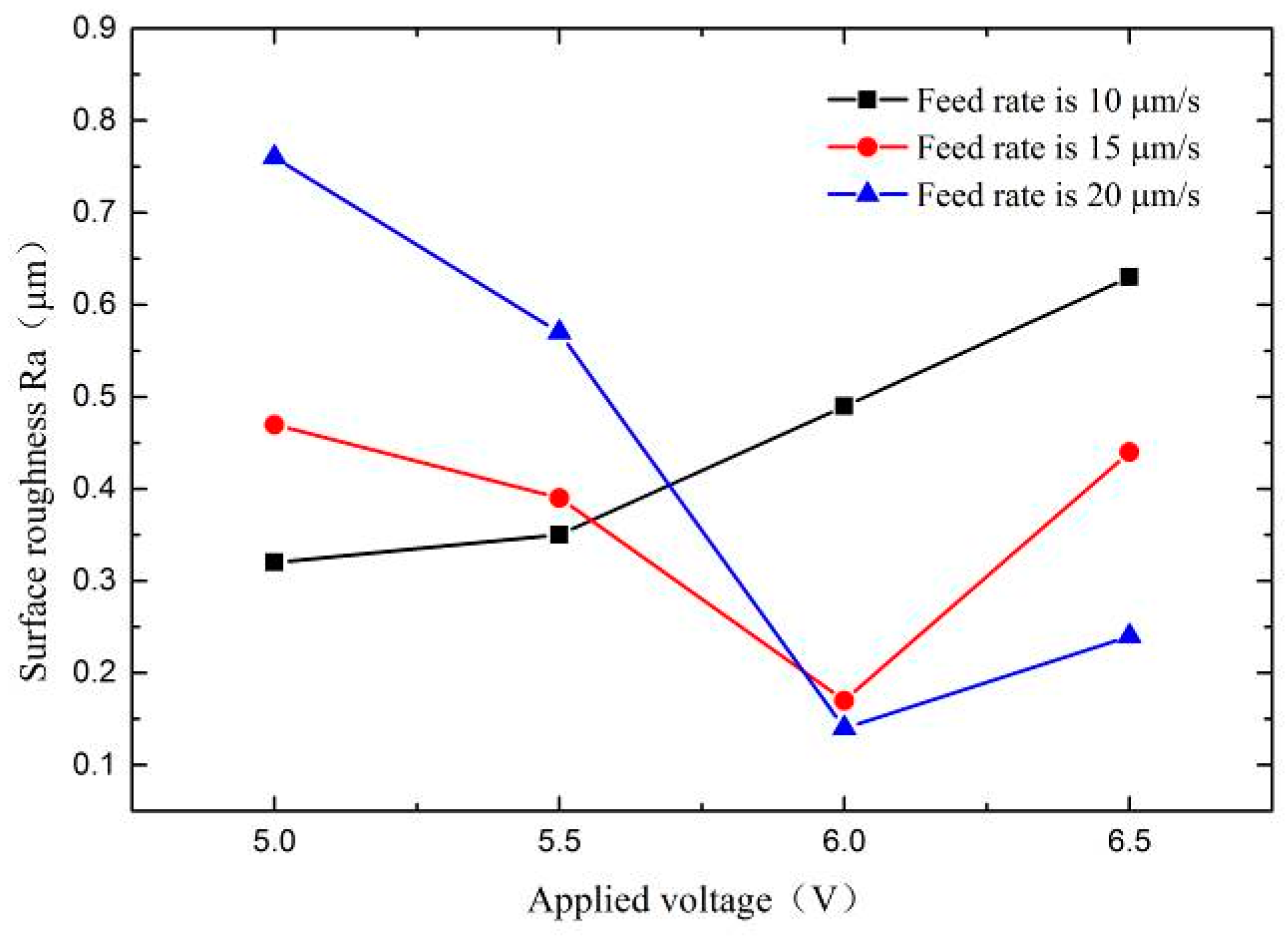
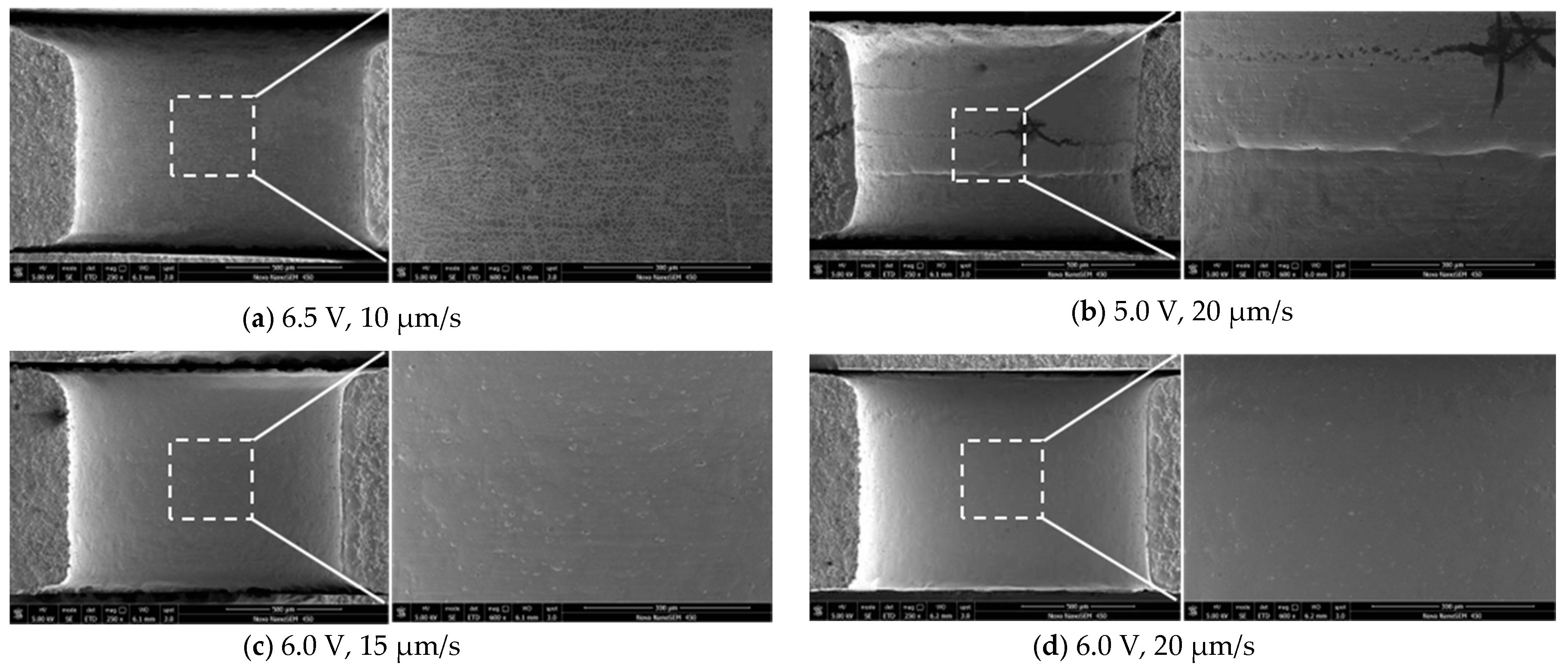
Figure 12 shows the effect of voltage and feed rate on the surface roughness of holes. It is indicated that the surface quality mainly depends on the matching between the applied voltage and feed rate. When low feed rate and high voltage are applied, the mechanical grinding in UAECDG is not working because the machining gap is too large, and the material is totally removed by electrochemical reaction.
The seriously stray corrosion occurs at the entrance of holes and the surface quality is suffered from the stray corrosion and pitting corrosion, which cause a poor surface quality as shown in Figure 13a. When high feed rate and low voltage are applied, the mechanical grinding is excessive and scraping the metal directly because of the too small machining gap, which cause an unstable machining process and even short circuit. The surface quality is damaged from the scratch produced by mechanical grinding as shown in Figure 13b. Only if the feed rate and voltage are balanced well will the holes have a good surface quality as shown in Figure 13c,d.
4.3. Experimental Result with Potimized Parameters
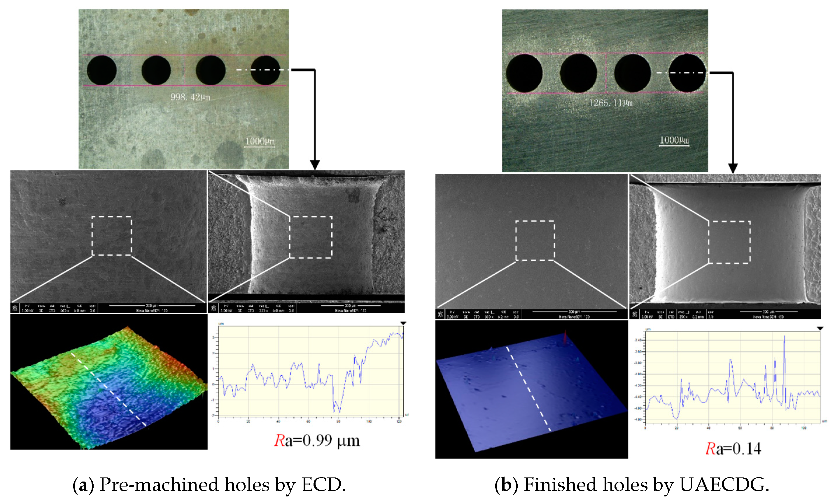
The parameters are optimized as follows: the applied voltage is 6 V, the feed rate is 20 μm/s, and the ultrasonic amplitude is 5 μm. By using the optimized parameters, a set of small holes with high repeat machining precision and surface quality are obtained. Figure 14 shows the diameter of the small holes is enlarged from 998 μm to 1265 μm. Benefiting from the applying of ball-end electrode, the machining localization is improved and the hole taper is obviously reduced by limiting the electrochemical reaction to the zone near the ball-end of electrode, which is consistent with simulation results. When the reasonable federate, voltage, and ultrasonic amplitude are applied, the UAECDG with a suitable machining gap has a good machining efficiency and stability. The side wall of the small hole is straighter and smoother after UAECDG along with the surface quality is improved from Ra 0.99 μm to Ra 0.14 μm. Figure 14a shows the pre-machined holes by ECD, Figure 14b shows the finished holes by UAECDG.
5. Conclusions
In this paper, an ultrasonic assisted electrochemical drill-grinding (UAECDG) technique is presented for the machining of GH3030 superalloy. To study passive behavior of GH3030 superalloy, the polarization curves of GH3030 superalloy in different passive electrolyte environments are investigated. The mathematical model and simulation of gap electric field are established to study the machining process of UAECDG. A series of experiments are conducted to study the effect of machining parameters on machining efficiency and quality. The machining parameters are optimized for fine machining of small holes on GH3030 superalloy with high machining efficiency and quality. The conclusions can be summarized as follows.
- (1)
- GH3030 superalloy has a passive behavior both in NaNO3 solution and NaClO3 solution. To obtain a stable passivation, the 20% NaNO3 solution is employed as an electrolyte in UAECDG because of the wider passive potential range, as well as the lower passive current density.
- (2)
- The electric field simulation of machining gap shows that electrochemical reaction can be restricted to the region around the ball-end of the tool electrode. By using the abrasive electrode with a ball-end, the machining localization can be improved and the hole taper can be reduced. In addition, the experiment results show that the hole wall is straighter after UAECDG by using the ball-end abrasive electrode.
- (3)
- The surface quality is determined by the balance of ECM and mechanical grinding. By applying an ultrasonic vibration with a proper amplitude on the tool electrode, the refreshment of the electrolyte is promoted and the machining efficiency and stability can be improved significantly. By optimizing the applied voltage, tool feed rate and ultrasonic amplitude, the small holes with high surface quality can be obtained. Compared with the surface machined by electrochemical drilling, the final surface machined by UAECDG is significantly improved with surface quality which demonstrates that the UAECDG is a highly promising technique to machine superalloy with high quality.
Author Contributions
Conceptualization, Y.L.; Formal analysis, T.P.; Investigation, H.K., X.Z., and T.P.; Project administration, Y.L.; Software, X.Z.; Writing—original draft, H.K.; Writing—review and editing, Y.L. All authors have read and agreed to the published version of the manuscript.
Funding
This research was funded by the National Key R&D Program of China 2018YFB1105900, the Key R&D Program of Shandong Province 2019GGX104023, the Natural Science Foundation of Shandong Province ZR2018MEE018, the China Postdoctoral Science Foundation 2018M630772, the Young Scholars Program of Shandong University, Weihai 2015WHWLJH03, and the Funding of Jiangsu Innovation Program for Graduate Education KYCX20_0181.
Conflicts of Interest
There is no conflict of interest.
References
- Zhan, T.; Chai, F.; Zhao, J.; Yan, F.; Wang, W. A study of microstructures and mechanical properties of laser welded joint in GH3030 alloy. J. Mech. Sci. Technol. 2018, 32, 2613–2618. [Google Scholar] [CrossRef]
- Xue, C.; Chen, W. Adhering layer formation and its effect on the wear of coated carbide tools during turning of a nickel-based alloy. Wear 2011, 270, 895–902. [Google Scholar] [CrossRef]
- Goswami, T. Conjoint bending torsion fatigue—Fractography. Mater. Des. 2002, 23, 385–390. [Google Scholar] [CrossRef]
- Imran, M.; Mativenga, P.; Gholinia, A.; Withers, P.J. Comparison of tool wear mechanisms and surface integrity for dry and wet micro-drilling of nickel-base superalloys. Int. J. Mach. Tools Manuf. 2014, 76, 49–60. [Google Scholar] [CrossRef]
- Zhu, D.; Zhang, X.; Ding, H. Tool wear characteristics in machining of nickel-based superalloys. Int. J. Mach. Tools Manuf. 2013, 64, 60–77. [Google Scholar] [CrossRef]
- Uçak, N.; Çiçek, A. The effects of cutting conditions on cutting temperature and hole quality in drilling of inconel 718 using solid carbide drills. J. Manuf. Process. 2018, 31, 662–673. [Google Scholar] [CrossRef]
- Sinha, M.K.; Setti, D.; Ghosh, S.; Rao, P.V. An investigation on surface burn during grinding of inconel 718. J. Manuf. Process. 2016, 21, 124–133. [Google Scholar] [CrossRef]
- Yılmaz, B.; Karabulut, Ş.; Güllü, A. Performance analysis of new external chip breaker for efficient machining of inconel 718 and optimization of the cutting parameters. J. Manuf. Process. 2018, 32, 553–563. [Google Scholar] [CrossRef]
- Wang, Y.L.; Chen, C.Y.; Liu, Z.C.; Ren, W.X.; Zhu, L.Z.; Wang, L. Machining and characterization of deep micro holes on super alloy processed by millisecond pulsed laser. Key Eng. Mater. 2016, 703, 34–38. [Google Scholar] [CrossRef]
- Pan, Z.; Feng, Y.; Hung, T.-P.; Jiang, Y.-C.; Hsu, F.-C.; Wu, L.-T.; Lin, C.-F.; Lu, Y.-C.; Liang, S.Y. Heat affected zone in the laser-assisted milling of inconel 718. J. Manuf. Process. 2017, 30, 141–147. [Google Scholar] [CrossRef]
- Lee, L.; Lim, L.; Narayanan, V.; Venkatesh, V. Quantification of surface damage of tool steels after EDM. Int. J. Mach. Tools Manuf. 1988, 28, 359–372. [Google Scholar] [CrossRef]
- Kliuev, M.; Florio, K.; Akbari, M.; Wegener, K. Influence of energy fraction in EDM drilling of inconel 718 by statistical analysis and finite element crater-modelling. J. Manuf. Process. 2019, 40, 84–93. [Google Scholar] [CrossRef]
- Rahman, Z.; Das, A.K.; Chattopadhyaya, S. Microhole drilling through electrochemical processes: A Review. Mater. Manuf. Process. 2017, 33, 1379–1405. [Google Scholar] [CrossRef]
- Maksoud, T.; Brooks, A. Electrochemical grinding of ceramic form tooling. J. Mater. Process. Technol. 1995, 55, 70–75. [Google Scholar] [CrossRef]
- Puri, A.B.; Banerjee, S. Multiple-response optimisation of electrochemical grinding characteristics through response surface methodology. Int. J. Adv. Manuf. Technol. 2012, 64, 715–725. [Google Scholar] [CrossRef]
- Curtis, D.; Soo, S.; Aspinwall, D.; Sage, C. Electrochemical superabrasive machining of a nickel-based aeroengine alloy using mounted grinding points. CIRP Ann. 2009, 58, 173–176. [Google Scholar] [CrossRef]
- Goswami, R.N.; Mitra, S.; Sarkar, S. Experimental investigation on electrochemical grinding (ECG) of alumina-aluminum interpenetrating phase composite. Int. J. Adv. Manuf. Technol. 2008, 40, 729–741. [Google Scholar] [CrossRef]
- Li, H.; Fu, S.; Zhang, Q.; Niu, S.; Qu, N. Simulation and experimental investigation of inner-jet electrochemical grinding of GH4169 alloy. Chin. J. Aeronaut. 2018, 31, 608–616. [Google Scholar] [CrossRef]
- Ming, P.M.; Zhu, D.; Xu, Z.Y. Electrochemical grinding for unclosed internal cylinder surface. Key Eng. Mater. 2007, 359, 360–364. [Google Scholar] [CrossRef]
- Zhu, D.; Zeng, Y.; Xu, Z.; Zhang, X. Precision machining of small holes by the hybrid process of electrochemical removal and grinding. CIRP Ann. 2011, 60, 247–250. [Google Scholar] [CrossRef]
- Qu, N.; Zhang, Q.; Fang, X.; Ye, E.; Zhu, D. Experimental investigation on electrochemical grinding of inconel 718. Procedia CIRP 2015, 35, 16–19. [Google Scholar] [CrossRef] [Green Version]
- Przystupa, K.; Litak, G. Electrochemical grinding of titanium-containing materials. Adv. Sci. Technol. Res. J. 2017, 11, 183–188. [Google Scholar] [CrossRef] [Green Version]
- Li, H.; Niu, S.; Zhang, Q.; Fu, S.; Qu, N. Investigation of material removal in inner-jet electrochemical grinding of GH4169 alloy. Sci. Rep. 2017, 7, 3482. [Google Scholar] [CrossRef] [PubMed] [Green Version]
- Li, H. Simulation and experimental investigation of electrochemical mill-grinding of GH4169 alloy. Int. J. Electrochem. Sci. 2018, 13, 6608–6625. [Google Scholar] [CrossRef]
- Niu, S.; Qu, N.; Yue, X.; Li, H. Effect of tool-sidewall outlet hole design on machining performance in electrochemical mill-grinding of inconel 718. J. Manuf. Process. 2019, 41, 10–22. [Google Scholar] [CrossRef]
- Niu, S.; Qu, N.; Li, H. Investigation of electrochemical mill-grinding using abrasive tools with bottom insulation. Int. J. Adv. Manuf. Technol. 2018, 97, 1371–1382. [Google Scholar] [CrossRef]
- Ge, Y.; Zhu, Z.; Wang, D.; Ma, Z.; Zhu, D. Study on material removal mechanism of electrochemical deep grinding. J. Mater. Process. Technol. 2019, 271, 510–519. [Google Scholar] [CrossRef]
- Zhu, X.; Liu, Y.; Zhang, J.; Wang, K.; Kong, H. Ultrasonic-assisted electrochemical drill-grinding of small holes with high-quality. J. Adv. Res. 2020, 23, 151–161. [Google Scholar] [CrossRef]
- Liu, Y.; Li, M.; Niu, J.; Lu, S.; Jiang, Y. Fabrication of taper free micro-holes utilizing a combined rotating helical electrode and short voltage pulse by ECM. Micromachines 2019, 10, 28. [Google Scholar] [CrossRef] [Green Version]
- Wang, D.; Zhu, Z.; Wang, N.; Zhu, D.; Wang, H. Investigation of the electrochemical dissolution behavior of inconel 718 and 304 stainless steel at low current density in NaNO3 solution. Electrochim. Acta 2015, 156, 301–307. [Google Scholar] [CrossRef]
Figure 1.
Experimental system for UAECDG.

Figure 2.
Tool electrode.

Figure 3.
Schematic diagram of machining process.

Figure 4.
Schematic diagram of gap electric field in the process.

Figure 5.
Simulation diagram of current density distribution and hole profile with UAECDG process.

Figure 6.
Polarization curves of GH3030 superalloy in different electrolyte environments.

Figure 7.
Schematic diagram of UAECDG.

Figure 8.
Schematic diagram of machining gap in UAECDG.

Figure 9.
Variation in maximum feed rate and minimum surface roughness Ra with ultrasonic amplitude.
Figure 9.
Variation in maximum feed rate and minimum surface roughness Ra with ultrasonic amplitude.

Figure 10.
Current signals during machining process with and without ultrasonic vibration.

Figure 11.
Variation in hole diameter with applied voltage and feed rate.

Figure 12.
Variation in hole surface roughness Ra with applied voltage and feed rate.

Figure 13.
Section view of small holes with different applied voltage and feed rate.

Figure 14.
Pre-machined hole by ECD and finished holes by UAECDG.


Table 1.
Parameters applied in the simulation
| Item | Value |
|---|---|
| Diameter of the pre-machined hole | 1 mm |
| Diameter of the ball-end | 1.1 mm |
| Diameter of the rod | 0.6 mm |
| Thickness of the workpiece | 1 mm |
| Electrical conductivity of the electrolyte | 11.6 S/m |
| Applied voltage | 6 V |
| Feed rate | 20 μm/s |
Table 2.
Parameters applied in the experiments.
| Item | Value |
|---|---|
| Diameter of the pre-machined hole | 1 mm |
| Diameter of tool electrode ball-end | 1.1 mm |
| Electrolyte | 20% NaNO3 solution |
| Rotating speed of tool electrode | 12,000 r/min |
| Applied voltage | 5.06.5 V |
| Feed rate | 10–20 μm/s |
| Ultrasonic amplitude | 0–10 μm |
| Ultrasonic frequency | 25 kHz |
© 2020 by the authors. Licensee MDPI, Basel, Switzerland. This article is an open access article distributed under the terms and conditions of the Creative Commons Attribution (CC BY) license (http://creativecommons.org/licenses/by/4.0/).
Share and Cite
MDPI and ACS Style
Kong, H.; Liu, Y.; Zhu, X.; Peng, T. Study on Ultrasonic Assisted Electrochemical Drill-Grinding of Superalloy. Chemosensors 2020, 8, 62. https://0-doi-org.brum.beds.ac.uk/10.3390/chemosensors8030062
AMA Style
Kong H, Liu Y, Zhu X, Peng T. Study on Ultrasonic Assisted Electrochemical Drill-Grinding of Superalloy. Chemosensors. 2020; 8(3):62. https://0-doi-org.brum.beds.ac.uk/10.3390/chemosensors8030062
Chicago/Turabian StyleKong, Huanghai, Yong Liu, Xiangming Zhu, and Tengfei Peng. 2020. "Study on Ultrasonic Assisted Electrochemical Drill-Grinding of Superalloy" Chemosensors 8, no. 3: 62. https://0-doi-org.brum.beds.ac.uk/10.3390/chemosensors8030062
Note that from the first issue of 2016, this journal uses article numbers instead of page numbers. See further details here.