Article

Corrosion Fatigue Behavior of Twin Wire Arc Sprayed and Machine Hammer Peened ZnAl4 Coatings on S355 J2C + C Substrate

1
Chair of Materials Test Engineering (WPT), TU Dortmund University, Baroper Str. 303, 44227 Dortmund, Germany
2
Institute of Machining Technology (ISF), TU Dortmund University, Baroper Str. 303, 44227 Dortmund, Germany
3
Chair of Materials Engineering (LWT), TU Dortmund University, Leonhard-Euler-Str. 2, 44227 Dortmund, Germany
*
Author to whom correspondence should be addressed.
Corros. Mater. Degrad. 2022, 3(1), 127-141; https://0-doi-org.brum.beds.ac.uk/10.3390/cmd3010007
Submission received: 23 December 2021 / Revised: 28 January 2022 / Accepted: 16 February 2022 / Published: 2 March 2022

Abstract

:
Offshore installations, e.g., offshore wind turbines and pipelines, are exposed to various mechanical loads due to wind or waves and corrosive loads such as seawater or mist. ZnAl-based thermal sprayed coatings, often in conjunction with organic coatings, provide sufficient corrosion protection and are well established for applications in marine environments. In this study, machine hammer peening (MHP) is applied after twin wire arc spraying to improve corrosion fatigue behavior through increased hardness, reduced porosity, and roughness compared to as-sprayed coatings. Mn-alloyed structural steel S355 J2 + C with and without ZnAl4 coating as well as with MHP post-treated ZnAl4 coating were cyclically loaded in 3.5% NaCl solution. MHP leads to a uniform coating thickness with lower porosity and roughness. ZnAl4 coating and MHP post-treatment improved corrosion fatigue behavior in the high cycle fatigue regime with an increase of the stress amplitude, applied to reach a number of cycles 1.2 × 10⁶, up to 115% compared to sandblasted specimens. Corrosive attack of the substrate steel was successfully avoided by using the coating systems. Stress- and microstructure-dependent corrosion fatigue damage mechanisms were evaluated by mechanical and electrochemical measurement techniques.

1. Introduction

Offshore wind turbines, pipelines, or bridges are examples of applications in the marine environment. In addition to requirements such as good weldability and cost-effectiveness, they must withstand various stresses resulting from superimposed mechanical and corrosive loads. Due to this, a combination of structural steel and corrosive metallic protective coatings has proved to be the best solution. Since repair costs offshore are up to 100 times higher than on land, reliable service life of at least 20 years should be guaranteed [1].
Corrosive protection of metallic coatings is based on various principles. Barrier coatings separate the substrate steel from the corrosive environment. Therefore, coatings must have sufficient adhesion to the substrate, adequate strength to resist first damage, and be suitably ductile to resist cracking [2]. Cathodic protection coatings additionally work as a sacrificial anode. Substrate material and coating form a galvanic couple with the metallic coating having a more negative electrode potential. If the coating is damaged and the substrate steel comes into contact with the corrosive medium, the coating will preferentially degrade. In marine applications, it is common to use organic coatings such as paintings as the second layer above the metallic coatings to improve the corrosion protection because it acts as a barrier coating [3]. If impressed cathodic protection is also applied, the coating requires a high electrical resistance [2]. In addition to corrosive stresses, various mechanical stresses act on structural elements in a marine environment, e.g., due to wind, waves, and tide. In case of offshore wind turbines, these mechanical stresses result in about 109 load cycles with an estimated service life of 20 years [4].
ZnAl-based coatings, which provide sufficient cathodic protection, are well established for applications in marine environments with additional organic coatings [5]. Besides Aluminum, other alloying elements such as Manganese or Silicon also improve the corrosion resistance of pure Zinc coatings [6,7,8]. Furthermore, the corrosion products of ZnAl coatings work as a barrier between the corrosive medium and coating or substrate [9].
ZnAl-based coatings can be applied by galvanization or thermal spraying processes. Due to the electroplating bath used during the galvanization process, the dimensions of the components to be coated are limited. Brittle Fe–Zn intermetallic phases formed during galvanization reduce the mechanical performance [9]. For the thermal spraying process, the dimensions of the parts to be coated are not limited and the heat supplied is lower than provided during galvanization [10]. The thermal spraying process produces coatings with higher porosity than galvanic coatings, a lamellar structure, and residual stresses [11]. Residual stresses can be introduced thermally or kinetically, whereas high temperatures lead to tensile residual stresses that reduce the fatigue strength of components and higher kinetic energy results in compressive stresses, which are known as beneficial for fatigue strength [12,13]. Thermal-sprayed ZnAl coatings produced by the twin wire arc spraying (TWAS) process also exhibit compressive residual stresses due to the effect of kinetic energy, as the impact of larger and not fully molten particles causes the thermal effect to surpass the kinetic effect [14].
Mechanical post-treatments of coatings can lead to improvement of the corrosion resistance by eliminating porosity, densification, and homogenization of the coating structure [15]. Machine hammer peening (MHP) generally reduces porosity, increases hardness, and introduces compressive residual stresses in near-surface areas [16,17]. This possibility of adjusting near-surface properties by MHP was also proven for ZnAl coatings [14,18].
In previous papers [19,20] of this study, the properties of the coating systems depending on the manufacturing process were investigated in detail. The use of argon and compressed air as atomizing gas in the TWAS process result in a lower oxide content in the case of compressed air [19]. Nevertheless, the oxides in form of small layers within the coating lead to cracks after MHP. Basically, Zn and Al rich regions can be distinguished and in addition oxide layers are formed. Thermally assisted MHP process have reduced and prevented this cracking by simultaneously increasing the hardness, introducing higher residual stresses, and reducing the porosity of ZnAl coatings compared to MHP processes conducted at room temperature [20].
Punchi-Carbera et al. [21] investigated the fatigue and corrosion fatigue resistance of Ni-based coatings deposited on a high strength steel by high-velocity oxygen fuel (HVOF). The fatigue life of coated specimens tested in air was lower compared to uncoated specimens due to the presence of alumina particles on the surface, which act as crack initiators. Comparative tests in NaCl solution showed an increase in the corrosion fatigue life of the coated specimens, as the coating served as a corrosion protection layer.
In previous fatigue tests in air of structural steel S355 JRC + C without and with ZnAl coating and with MHP post-treated ZnAl coating, the ZnAl-coated and MHP post-treated specimens showed better fatigue strength in the high fatigue regime.
The aim of this study was to improve the corrosion fatigue properties by adjusting the coating properties. Therefore, mechanical compacting by MHP was performed, which should induce a reduction of porosity and roughness, as well as an increase of compressive residual stresses and hardness. Instrumented corrosion fatigue tests were carried out in 3.5%NaCl solution at various stress amplitudes. Mechanical and electrochemical measuring techniques were applied to determine the corrosion fatigue damage mechanisms.

2. Materials and Methods

2.1. Materials and Manufacturing

Three specimen conditions I–III of the structural Mn-alloyed steel S355 J2C + C were investigated. The base material was sandblasted (I) before applying a ZnAl4-coating (II) and subsequently MHP post-treated (III). The manufacturing process of the conditions I–III is described in detail below. All tests were performed using specimens with a geometry according to Figure 1.

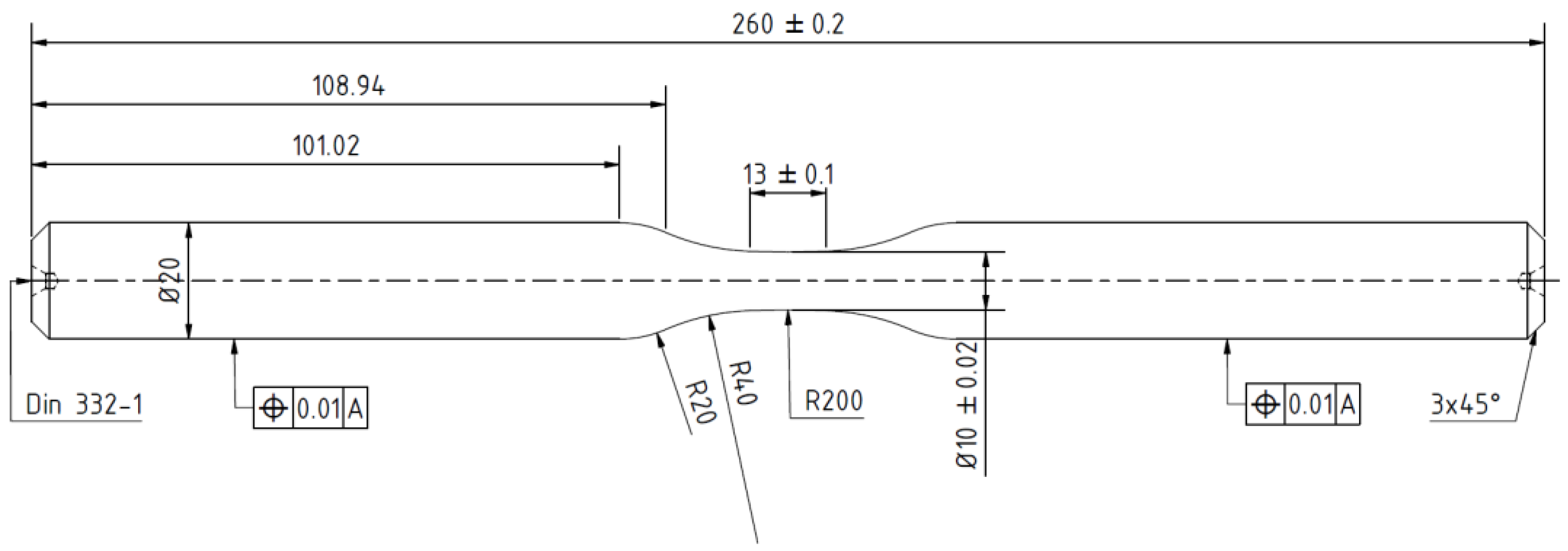
2.1.1. Substrate Material

The structural steel S355 J2C + C (1.0579) was sandblasted and used as substrate material for the coating systems. Table 1 and Table 2 show the chemical composition and material properties of the steel according to the datasheet of the manufacturer.
Sandblasting was carried out to ensure sufficient adhesion for the following ZnAl4 coating. Therefore, Alumina oxide powder with EKF 24 (600–850 µm) size fraction, 4 bar blasting pressure, 100 mm stand-off distance, and 45° blasting angle has been used for manufacturing. An ultrasonic ethanol bath enables the removal of dust residues and the final cleaning of the sandblasted surfaces.

2.1.2. Twin Wire Arc Spray Process

Twin-wire arc spraying (TWAS) process was carried out using a spray unit Durum Duraspray 450 (Durum, Germany) to apply ZnAl4 coatings on sandblasted specimens. Contaminations of the surface were removed using ethanol. The process was exclusively performed within the rejuvenated specimen area. The chemical composition of the feedstock wires made of ZnAl4 is given in Table 3.
The TWAS process was performed with 3.2 m/min wire feed rate, 22 V arc voltage, and 5 bar atomization gas pressure using atomization gas dry and compressed air. An industrial robot, ABB IRB 4600, and a rotating unit with the handling parameters 120 mm stand-off distance between the spray gun and substrate surface, vs = 18,000 mm/min axial gun velocity, and s = 4 mm meander spacing were used. Coatings were made in 4 gun overruns in total. The specimens were masked, except of the rejuvenated specimen area during the spraying process to avoid the coating of unwanted areas.

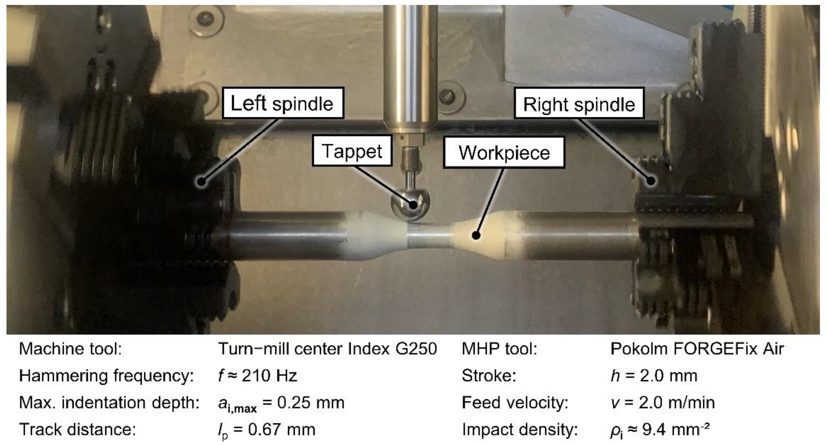
2.1.3. Machine Hammer Peening Process

Coated specimens were machine hammer-peened using a high-performance turn-mill center Index G250 (Index-Werke, Esslingen, Germany) with a Pokolm FORGEFix Air MHP tool using a spherical solid carbide tappet with diameter dp = 16 mm (Figure 2).
The process parameter settings were chosen based on former studies [14,22]. A compressed air pressure p = 6 bar resulted in a hammering frequency f ≈ 210 Hz with a stroke set to h = 2.0 mm. A feed speed vf = 2.0 m/min, a maximal indentation depth ai,max ≈ 0.25 mm, and a line pitch lp = 0.67 mm were used. The process parameter resulted in an impact density of about pi = 9.4 indents/mm2. Figure 3 shows the gauge length of sandblasted (I), ZnAl-coated (II), and MHP post-treated (III) specimens.

2.2. Material Characterization and Testing Methods

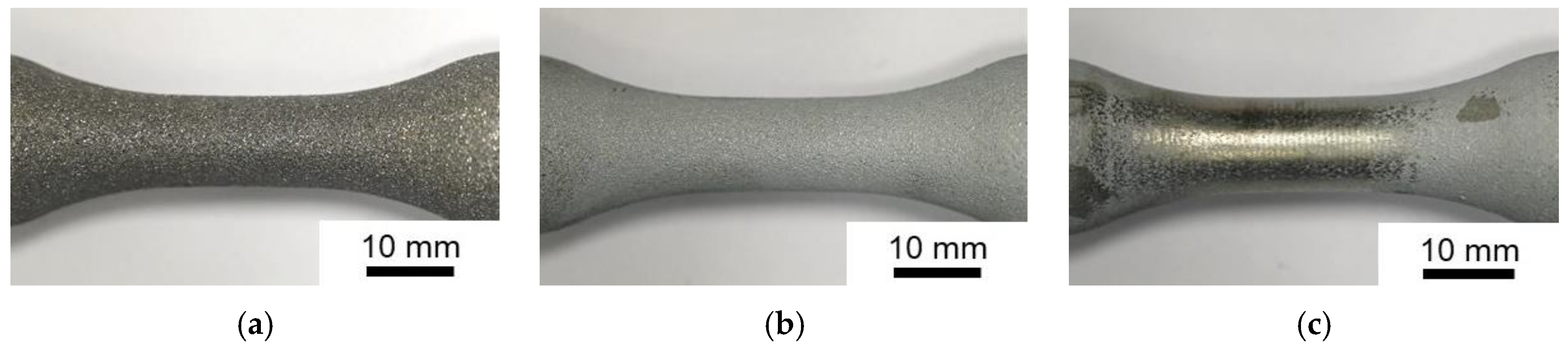
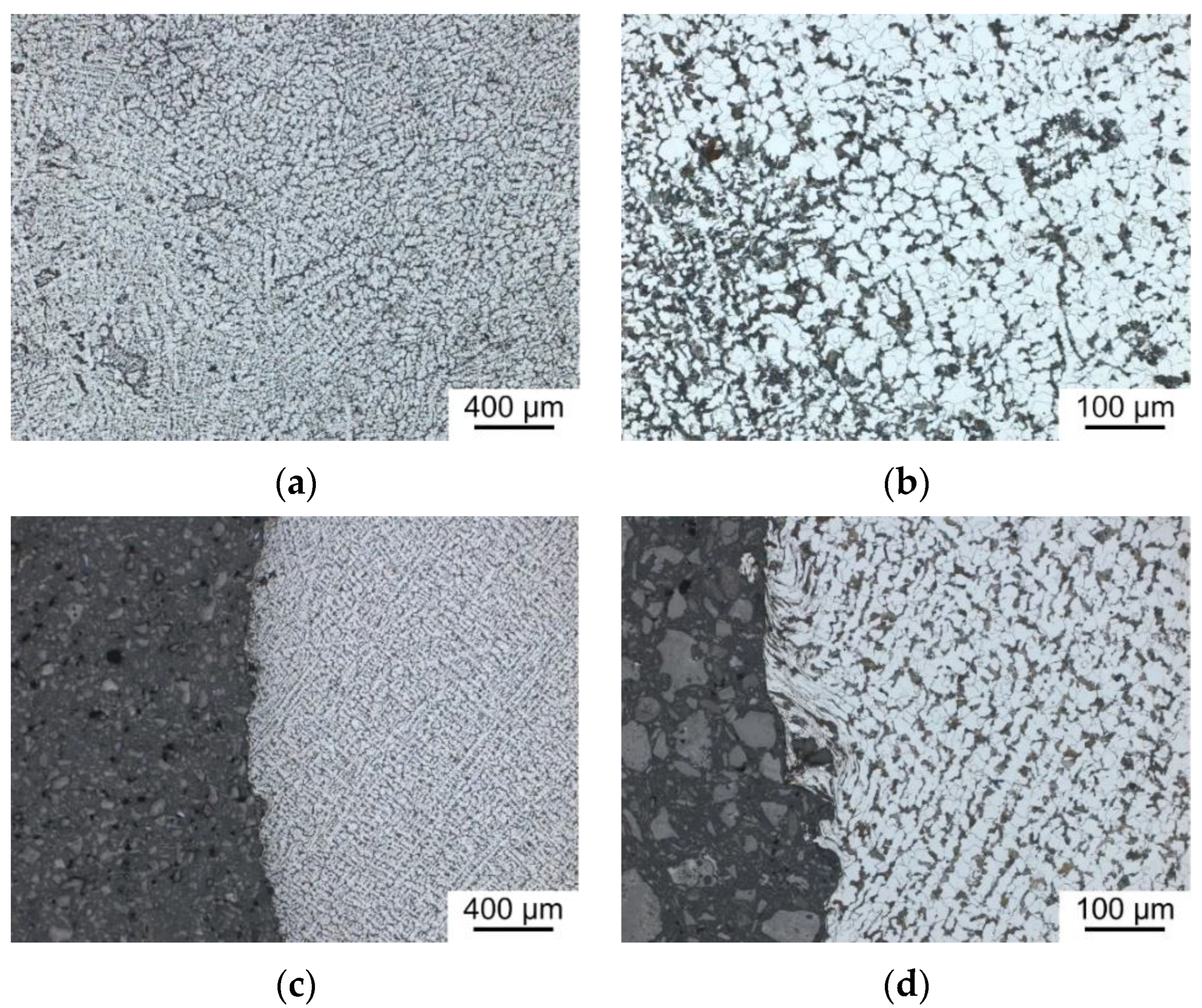
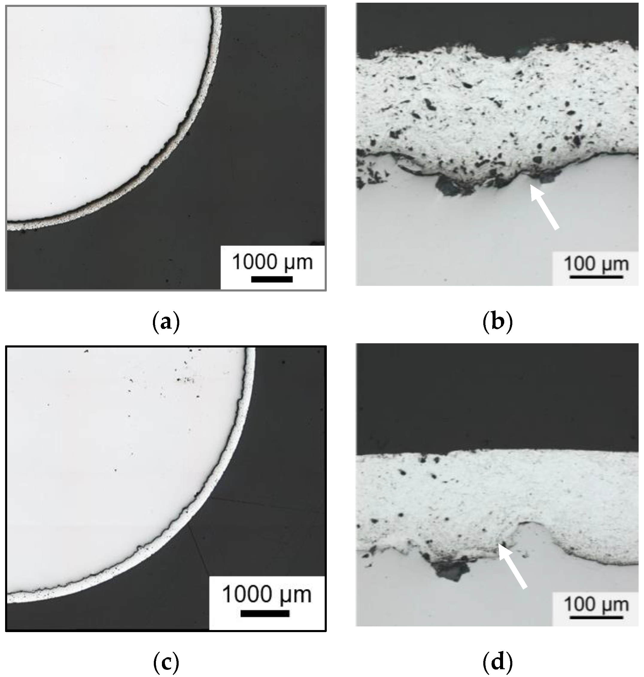
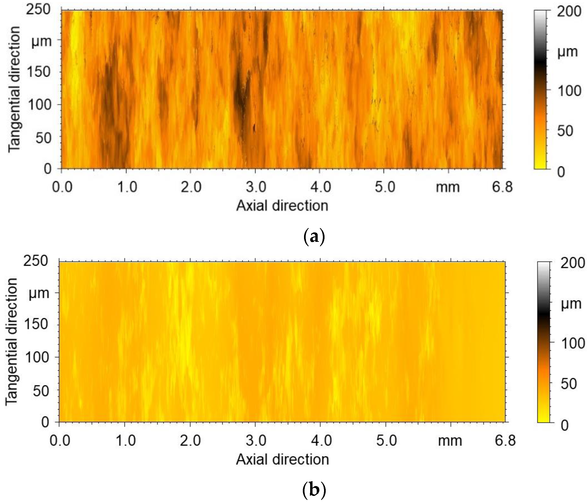
2.2.1. Macro- and Microstructure Investigations

Surface qualities of specimen conditions I–III were evaluated by roughness measurements and metallographic characterization. Mean roughness depth Rz, arithmetical mean roughness Ra, mean smoothing depth Rp, thickness, and hardness of the coatings were characterized before and after the MHP post-treatment. Roughness parameters were determined using a confocal white light microscope Nanofocus μsurf (Oberhausen, Germany) with a magnification 50× long objective and a robust Gaussian filter with a cutoff wavelength λc = 0.8 mm. Metallographically prepared cross-sections were used to determine substrate grain structure, coating morphology, and coating thickness by means of an Olympus BX51 optical microscope (Hamburg, Germany). For corrosion fatigue tests, the diameter of the gauge length was measured using the optical micrometer Keyence TM-040 (Neu-Isenburg, Germany). After each processing step, three measurements were carried out and the average values were calculated.

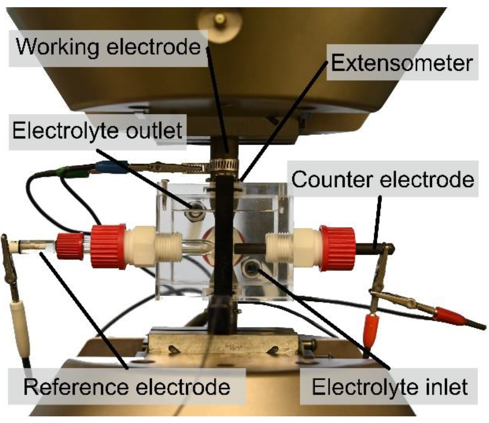
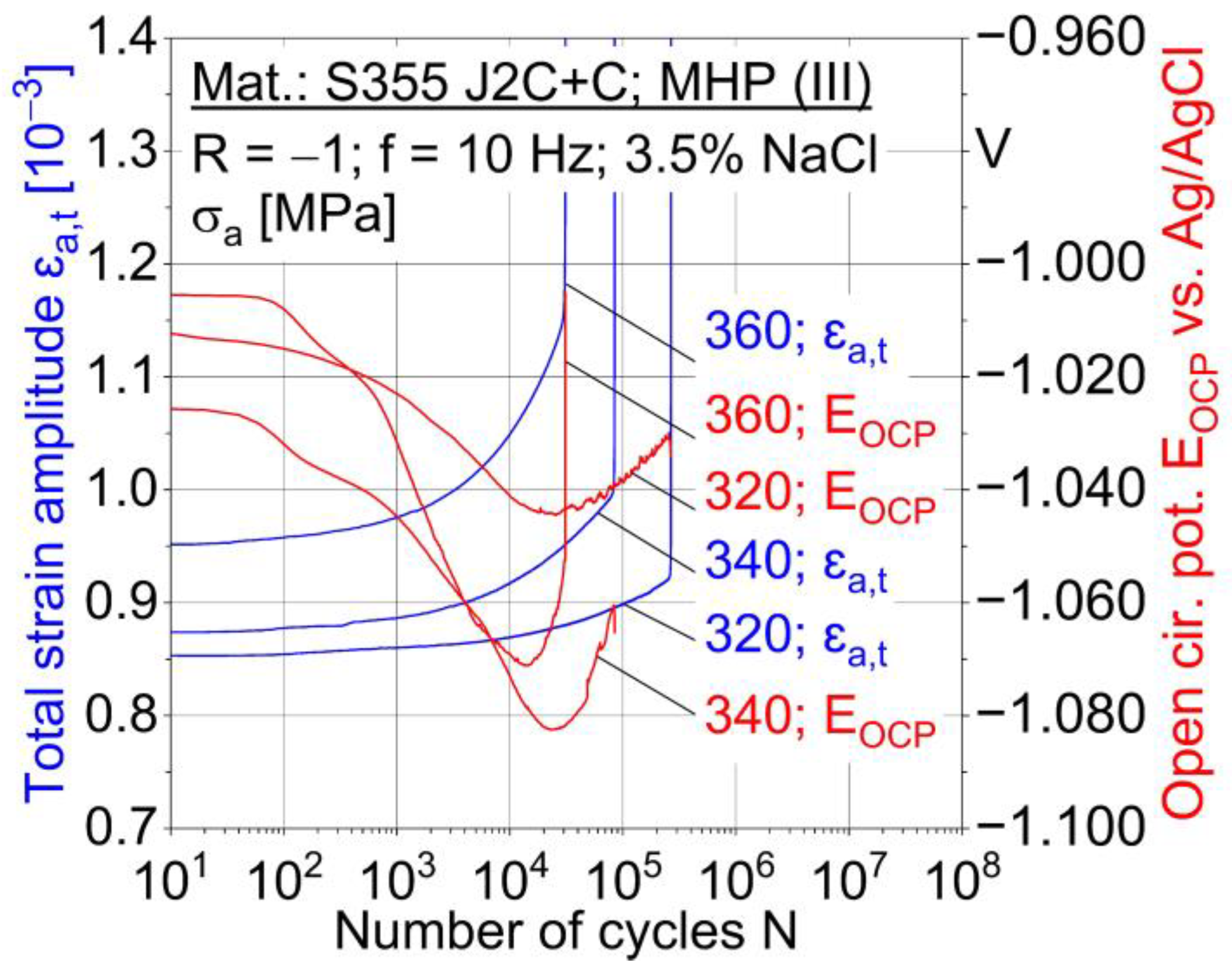
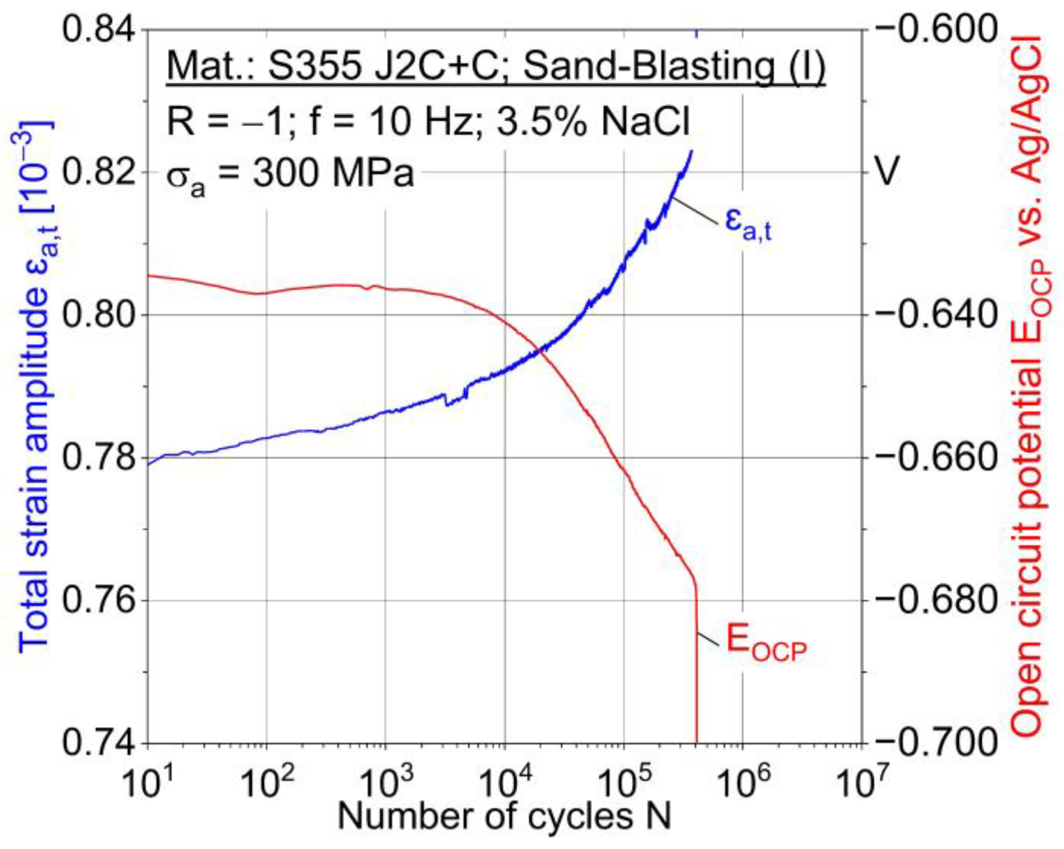
2.2.2. Corrosion Fatigue Testing

For corrosion fatigue characterization, constant amplitude tests (CAT) were performed stress-controlled with a sinusoidal load-time function at a stress ratio R = −1 (fully-reversed loading). According to previous tests, stress amplitudes in the range of 280 to 360 MPa were selected. The fatigue stresses were calculated based on the initial diameter of sandblasted specimens, for all specimen conditions I–III. CAT ended with failure or reaching the limited number of cycles Nlimit = 2 × 10⁶. The specimens were coated with polyurethane, except a 9 mm wide area in the middle of the gauge length, in order to create a defined test area for electrochemical measurements during fatigue loading.
A self-designed corrosion cell was used to perform corrosion fatigue tests in 3.5% NaCl solution, as shown in Figure 4. Continuous exchange and tempering of the corrosion medium was controlled by a pump and thermostat. Polymer seals were used to enable the sealing of the cell. As the installation of the extensometer inside the corrosion cell was not possible, an extensometer with 89 mm gauge length was applied at the specimens shafts outside the cell. Corrosion behavior and damage mechanisms during corrosion fatigue tests were evaluated using a three-electrode setup and a potentiostat interface 1000 (Gamry instruments, Warminster, PA, USA). Thereby, the specimen dealt as the working electrode, a silver chloride electrode was used as the reference electrode, and a graphite electrode served as the counter electrode. Before fatigue loading, the specimens were exposed for 30 to 60 min (30 min: sandblasted (I); 60 min: (ZnAl-coated (II), MHP post-treated (III)) to the medium in order to reach their specific open circuit potential (OCP).

3. Results and Discussion

3.1. Substrate Material and Coating Systems Characterization

The Mn-alloyed structural steel S355 J2C + C has a ferritic-pearlitic microstructure, as shown in light micrographs, Figure 5a,b. The sample was etched with 5% Nital solution. White areas are ferritic, dark areas pearlitice. The rough surface and plastic deformations at the specimen surface are a result of the sandblasting process, Figure 5c,d.
Light micrographs of ZnAl-coated (II) and MHP post-treated (III) specimens show an intact and continuous coating over the whole circumference, Figure 6a,c. A higher number of pores and a rougher surface can be determined for the ZnAl-coating (II) (Figure 6b) compared to the MHP post-treated (III) coating (Figure 6d). Furthermore, the adhesion of the coating to the substrate appears to be improved as a result of MHP process, as the width of gaps between the substrate and the coating (white arrows) are reduced, Figure 6b,d.
Three values of the coating thickness were determined at three locations for each specimen condition using light micrographs in order to calculate the average value and standard deviations; Table 4. The average coating thickness of all measurements differs by 9.9 µm. The significant value is the standard deviation, which is 13.1 µm higher for ZnAl-coated (II) specimens. Due to this, mechanical compacting by MHP leads to a more homogenous and constant coating thickness.
A smoothening of the surface by MHP, which was determined in optical micrographs (Figure 6), can be confirmed by axial roughness line scans for 250 µm width and 6.8 mm length (Figure 7). Two specimens were evaluated for each specimen condition I–III. Highest roughness values were determined for the sandblasted specimens; Table 4. The mean values of the arithmetical mean roughness Ra and mean roughness depth Rz have been reduced by more than 50% for MHP post-treated (III) specimen compared to the ZnAl-coated (II) specimen.

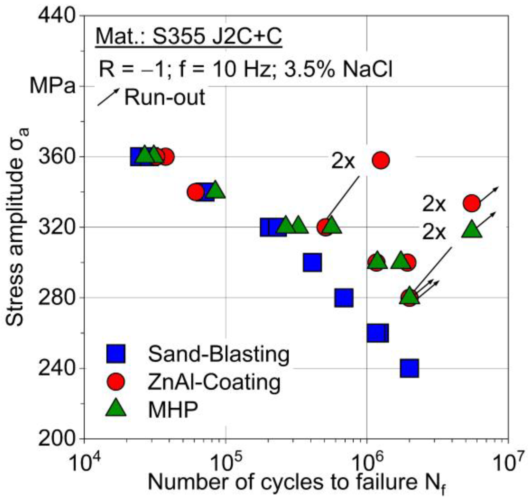
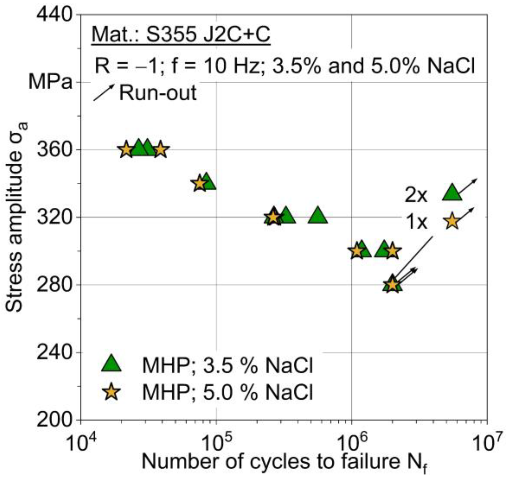
3.2. Corrosion Fatigue Testing

Corrosion fatigue tests were performed at five and six stress amplitudes, respectively, with a minimum of nine specimens tested per condition. Figure 8 shows the cyclic deformation curves for MHP post-treated (III) specimens at three stress amplitudes. As expected, higher stress amplitudes lead to increasing strain amplitudes and decreasing lifetimes.
OCP decreases at the test beginning because new deformation-induced surface areas are in contact with the electrolyte. The decrease is more pronounced for higher stress amplitudes. Minimum OCP values are reached at 104 to 3 × 10⁴ cycles. The following increase is expected to be a result of corrosion fatigue damage mechanisms within the substrate steel, which shows a significantly higher OCP than the coatings; Figure 8. After fatigue crack initiation in the substrate, the OCP increase is more pronounced for ongoing fatigue loading, as more deformation- and damage-induced surface areas of the substrate steel get into contact with the electrolyte. In comparison, OCP of sandblasted (I) specimens start at a higher level and constantly decreases until failure, as corrosion fatigue damage mechanisms of the substrate are exclusively relevant; Figure 9.
A higher deformation rate due to higher stress amplitude also leads to more pronounced OCP changes. Consequently, the correlation of mechanical and electrochemical measurement techniques is well suitable to describe corrosion fatigue damage mechanisms of the material S355 J2C + C without and with ZnAl-coating (II) and MHP post-treatment (III).
Based on the change in OCP, the stress-dependent corrosion fatigue damage behavior can be evaluated in detail; Figure 10. The change in open circuit potential ∆Eocp is calculated based on the specific potential after the exposure time without load and current potential. Higher stress amplitudes promote damage mechanisms, which can be related to the amount and width of cracks, leading to failure at lower lifetimes. The more pronounced decrease for higher stress amplitudes is expected to be a result of plastic deformation, crack initiation, and propagation within the coating. The following crack propagation within the substrate is also accelerated by higher stresses, resulting in a rapid OCP increase. The OCP minimum is reached earlier for higher stresses and is well suitable to indicate the beginning of corrosion fatigue damage within the substrate.
Figure 11 shows the S-N diagram for specimen conditions sandblasted (I), ZnAl-coated (II) and machine hammer-peened (III). In the low cycle fatigue (LCF) range, the lifetime is nearly independent of specimen conditions. Measured numbers of cycles to failure differ in a small range of 24,000 to 38,000 (360 MPa), and 60,000 to 85,000 (340 MPa).
For decreasing stress amplitude and increasing testing time in a corrosive environment, the improvement of the corrosion fatigue performance due to ZnAl-coating (II) and MHP post-treatment (III) is more pronounced. The stress amplitude, applied to reach a number of cycles to failure Nf = 1.2 × 10⁶ can be increased from 260 to 300 MPa, i.e., +15%, due to additional ZnAl-coating (II) and MHP post-treatment (III). While specimens II and III run-out at 280 MPa, specimen I failed at 260 MPa. On comparing the fatigue performance of ZnAl-coated and MHP post-treated specimens within the investigated loading range, no significant differences were determined. A further improvement of the performance for longer test durations and more aggressive media by the MHP process is expected, since the surface is smooth and the number and size of pores within the coating are decreased.
For evaluation of the test media influence, additional fatigue tests were carried out in 5% NaCl solution with MHP post-treated (III) specimens; Figure 12. This increase in NaCl content does not lead to significant difference in corrosion fatigue behavior.
After corrosion fatigue testing, sandblasted (I) specimens loaded at 320 MPa show a significant corrosive attack within the gauge length and on the fracture surface (Figure 13a,b). In comparison, the corrosive attack of MHP post-treated (III) specimens, also tested at 320 MPa, is limited to the coating, as white corrosive products of ZnAl had formed (Figure 13c,d). Due to this, the corrosive attacks on the substrate seem to be successfully avoided by using the coating as corrosion protection. After 56 h corrosion fatigue testing at 280 MPa without fracture, cracks in the coating and corrosion products of the ZnAl-coating (II) can be detected for MHP post-treated (III) specimens (Figure 13e). Consequently, the ZnAl-coating (II) is well suited to act as a sacrificial anode and protect the underlying substrate from corrosion.
On the fracture surface of MHP post-treated (III) specimens, which were tested at 300 MPa in 3.5% NaCl solution, the crack initiation can be located at the specimen surface (Figure 14b,c and Figure 15b). The fatigue fracture area, where the fatigue crack propagates under lower deformation features and with formation of fatigue striations (Figure 14d), can be distinguished from the region of sudden failure. The white arrows mark fatigue striations and a side crack along a fatigue striation. This behavior is characteristic for all specimen conditions and stress amplitudes (Figure 15a,b). The area of sudden failure is characterized by a ductile dimple fracture, which is common for structural steels (Figure 15c,d). A distinct corrosion attack cannot be observed for coated (II) and MHP post-treated (III) specimens.

4. Conclusions and Outlook

The combination of twin wire arc spraying (TWAS) and machine hammer peening (MHP) resulted in coating thicknesses above 200 µm, covering the entire substrate material S355 J2C + C without cracks vertical to the substrate. MHP improved the roughness of the ZnAl coatings with a reduction of the arithmetical mean roughness and mean roughness depth by over 50%. The MHP process also created a more consistent coating thickness throughout the specimen and less porosity.
Direct correlations of material reactions by means of mechanical and electrochemical measurement techniques and corrosion fatigue damage mechanisms were determined for the three conditions: sandblasted (I), ZnAl-coated (II), and MHP post-treated (III). Higher total strain amplitudes for higher stress amplitudes lead to a more significant change in the open circuit potential (OCP). As a result of plastic deformation, newly generated surface gets in contact with the electrolyte and reduces the OCP in case of the coating systems II and III. Therefore, the initial decrease in OCP of MHP-treated (III) samples is expected to be related to the change in coating properties due to deformation, microcrack formation, and crack propagation within the coating. A significant increase of OCP for ZnAl-coated (II) and MHP post-treated (III) specimens indicated crack propagation, which reached the substrate steel. Further increase in OCP is a result of more substrate material in contact with the electrolyte due to crack initiation and propagation. The assumptions will be confirmed by interrupted corrosion fatigue tests to verify the relationship between cyclic deformation, fatigue crack mechanisms, and electrochemical measurements.
ZnAl-coated (II) and MHP post-treated (III) coating systems significantly improved corrosion fatigue behavior at lower stress amplitudes (260 to 320 MPa) compared to sandblasted (I) specimens. ZnAl coating (II) and MHP post-treatment (III) can increase the stress amplitude applied to achieve a defined lifetime compared to sandblasted (I) specimens. In the low cycle fatigue (LCF) regime, the corrosion fatigue performance of all conditions was similar, as the corrosive attack was negligible. There is no difference in corrosion resistance between ZnAl-coated (II) and MHP post-treated (III) specimens, as condition II already provides sufficient corrosion protection. Consequently, a further improvement of the corrosion fatigue performance in the high cycle fatigue (HCF) regime is expected for more severe corrosive loading due to more aggressive media or longer test durations. This study presents the high potential of the ZnAl-coating and MHP post-treatment, as most applications in the maritime sector are subjected to HCF loading.
In future studies, fatigue tests in air will be evaluated in combination with potentiodynamic polarization measurements of the three conditions in order to separate mechanical and corrosion damage effects. Additional corrosion fatigue tests in more aggressive medium and under anodic polarization will be used to present further improvement of the corrosions fatigue performance achieved by MHP processing.

Author Contributions

Conceptualization, M.P.M., A.W., M.A., D.B., W.T. and F.W.; methodology, M.P.M.; software, M.P.M.; validation, M.P.M.; formal analysis, M.P.M.; investigation, M.P.M., A.W. and M.A.; resources, D.B., W.T. and F.W.; data curation, M.P.M.; writing—original draft preparation, M.P.M.; writing—review and editing, M.P.M., A.W., M.A., A.K., D.B., W.T. and F.W.; visualization, M.P.M. and A.K.; supervision, D.B., W.T. and F.W.; project administration, D.B., W.T. and F.W.; funding acquisition, D.B., W.T. and F.W. All authors have read and agreed to the published version of the manuscript.

Funding

The authors gratefully acknowledge the funding by the German Research Foundation (Deutsche Forschungsgemeinschaft, DFG) of the project “Process parameters correlated characterization of the corrosion fatigue behavior of post-treated ZnAl-coated arc-sprayed systems” (project number 426365081).

Institutional Review Board Statement

Not applicable.

Informed Consent Statement

Not applicable.

Data Availability Statement

Not applicable.

Conflicts of Interest

The authors declare no conflict of interest.

References

  1. Mühlberg, K. Corrosion protection of offshore wind turbines—A challenge for the steel builder and paint applicator. J. Prot. Coat. Linings 2010, 27, 20–33. [Google Scholar]
  2. Masi, G.; Matteucci, F.; Tacq, J.; Balbo, A. State of the Art Study on Materials and Solutions Against Corrosion in Offshore Structures, 3rd ed.; North Sea Solutions for Innovation in Corrosion for Energy, 2019; pp. 37–40. Available online: http://nessieproject.com/library/reports-and-researches/NeSSIE%20Report%20Study%20on%20Materials%20and%20Solutions%20in%20Corrosion (accessed on 22 December 2021).
  3. Momber, A.W.; Marquardt, T. Protective coatings for offshore wind energy devices (OWEAs): A review. J. Coat. Technol. Res. 2018, 15, 13–40. [Google Scholar] [CrossRef]
  4. Schaumann, P.; Lochte-Holtgreven, S.; Steppeler, S. Special fatigue aspects in support structures of offshore wind turbines. Mater. Werkst. 2011, 42, 1075–1081. [Google Scholar] [CrossRef]
  5. Panossian, Z.; Mariaca, L.; Morcillo, M.; Flores, S.; Rocha, J.; Peña, J.J.; Herrera, F.; Corvo, F.; Sanchez, M.; Rincon, O.D.; et al. Steel cathodic protection afforded by zinc, aluminium and zinc/aluminium alloy coatings in the atmosphere. Surf. Coat. Technol. 2005, 190, 244–248. [Google Scholar] [CrossRef]
  6. Choe, H.B.; Lee, H.S.; Shin, J.H. Experimental study on the electrochemical anti-corrosion properties of steel structures applying the arc thermal metal spraying method. Materials 2014, 7, 7722–7736. [Google Scholar] [CrossRef] [PubMed] [Green Version]
  7. Bobzin, K.; Oete, M.; Linke, T.F.; Schulz, C. Corrosion of wire arc sprayed ZnMgAl. Mater. Corros. 2015, 66, 520–526. [Google Scholar] [CrossRef]
  8. Sugimura, S.; Liao, J. Long-term corrosion protection of arc spray Zn-Al-Si coating system in dilute chloride solutions and sulfate solutions. Surf. Coat. Technol. 2016, 302, 398–409. [Google Scholar] [CrossRef]
  9. Shih, H.C.; Hsu, J.W.; Sun, C.N.; Chung, S.C. The lifetime assessment of hot-dip 5% Al-Zn coatings in chloride environments. Surf. Coat. Technol. 2002, 150, 70–75. [Google Scholar] [CrossRef]
  10. Syrek-Gerstenkorn, B.; Paul, S.; Davenport, A.J. Sacrificial thermally sprayed aluminium coatings for marine environments: A review. Coatings 2020, 10, 267. [Google Scholar] [CrossRef] [Green Version]
  11. Wielage, B.; Lampke, T.; Grund, T. Thermal spraying of wear and corrosion resistant surfaces. Key Eng. Mater. 2008, 384, 75–98. [Google Scholar] [CrossRef]
  12. Radaj, D.; Vormwald, M. Einflüsse auf die Schwingfestigkeit. In Ermüdungsfestigkeit Grundlagen für Ingenieure, 3rd ed.; Springer: Berlin/Heidelberg, Germany, 2007; pp. 110–121. [Google Scholar]
  13. Chen, Y.; Liang, X.; Liu, Y.; Xu, B. Prediction of residual stresses in thermally sprayed steel coatings considering the phase transformation effect. Mater. Des. 2010, 31, 3852–3858. [Google Scholar] [CrossRef]
  14. Tillmann, W.; Abdulgader, M.; Hagen, L.; Biermann, D.; Timmermann, A.; Wirtz, A.; Walther, F.; Milz, M. Mechanical and microstructural properties of post-treated Zn4Al sprayed coatings using twin wire arc spraying. In Proceedings of the International Thermal Spray Conference, Virtual, 24–28 May 2021; Azarmi, F., Chen, X., Cizek, J., Cojocaru, C., Jodoin, B., Koivuluoto, H., Lau, Y., Fernandez, R., Ozdemir, O., Salami Jazi, H., et al., Eds.; ASTM International: Novelty, OH, USA, 2021; pp. 750–757. [Google Scholar] [CrossRef]
  15. Wielage, B.; Grund, T.; Pokhmurska, H.; Rupprecht, C.; Lampke, T. Tailored surfaces by means of thermal spraying and post-treatment. Key Eng. Mater. 2008, 384, 99–116. [Google Scholar] [CrossRef]
  16. Hacini, L.; Van Lê, N.; Bocher, P. Effect of impact energy on residual stresses induced by hammer peening of 304L plates. J. Mater. Proc. Technol. 2008, 208, 542–548. [Google Scholar] [CrossRef]
  17. Adjassoho, B.; Kozeschnik, E.; Lechner, C.; Bleicher, F.; Goessinger, S.; Bauer, C. Induction of residual stresses and increase of surface hardness by machine hammer peening technology. In Annals of DAAAM for 2012 & Proceedings of the 23rd International DAAAM Symposium, Zadar, Croatia, 24–27 October 2012; DAAAM International: Vienna, Austria, 2012; Volume 23, pp. 697–702. [Google Scholar]
  18. Timmermann, A.; Abdulgader, M.; Hagen, L.; Milz, M.; Wirtz, A.; Biermann, D.; Tillmann, W.; Walther, F. Charakterisierung lichtbogengespritzter, mittels Machine Hammer Peening nachbehandelter Korrosionsschutzschichten. Therm. Spray Bull. 2021, 14, 46–52. [Google Scholar]
  19. Tillmann, W.; Abdulgader, M.; Wirtz, A.; Milz, M.; Biermann, D.; Walther, F. The effect of Argon as atomization gas on the microstructure, machine hammer peening post-treatment, and corrosion behavior of twin wire arc sprayed (TWAS) ZnAl4 coatings. Coatings 2022, 12, 32. [Google Scholar] [CrossRef]
  20. Wirtz, A.; Abdulgader, M.; Milz, M.; Tillmann, W.; Walther, F.; Biermann, D. Thermally assisted machine hammer peening of arc-sprayed ZnAl-based corrosion protective coatings. J. Manuf. Mater. Proc. 2021, 5, 109. [Google Scholar] [CrossRef]
  21. Puchi-Cabrera, E.S.; Staia, M.H.; Lesage, J.; Chicot, D.; La Barbera-Sosa, J.G.; Ochoa Pérez, E.A. Fatigue performance of a SAE 1045 steel coated with a Colmonoy 88 alloy deposited by HVOF thermal spraying. Surf. Coat. Technol. 2006, 201, 2038–2045. [Google Scholar] [CrossRef]
  22. Timmermann, A.; Abdulgader, M.; Hagen, L.; Koch, A.; Wittke, P.; Biermann, D.; Tillmann, W.; Walther, F. Effect of machine hammer peening on the surface integrity of a ZnAl-based corrosion protective coating. In Proceedings of the MATEC Web of Conferences, Thessaloniki, Greece, 2–3 July 2020; p. 1008. [Google Scholar] [CrossRef]
Figure 1. Specimen geometry, all dimensions in mm.
Cmd 03 00007 g001
Figure 2. Setup of the machine hammer peening (MHP) process using turn-mill center index G250.
Cmd 03 00007 g002
Figure 3. Gauge length of specimen conditions I–III: (a) sandblasted (I), (b) ZnAl-coated (II), (c) MHP post-treated (III).
Cmd 03 00007 g003
Figure 4. Experimental corrosion fatigue test setup.
Cmd 03 00007 g004
Figure 5. Polished cross-section of sandblasted (I) specimen, (a,b) microstructure of the center area, (c,d) microstructure of the edge area.
Cmd 03 00007 g005
Figure 6. Polished cross-section of ZnAl-coated (II) specimen as (a) overview and (b) detail and of the MHP post-treated (III) specimen as (c) overview and (d) detail.
Cmd 03 00007 g006
Figure 7. Axial roughness line scans for (a) ZnAl-coated (II) and (b) MHP post-treated (III) specimens.
Cmd 03 00007 g007
Figure 8. Cyclic deformation curves for corrosion fatigue tests of machine hammer-peened (III) specimens in 3.5% NaCl solution.
Cmd 03 00007 g008
Figure 9. Corrosion fatigue tests of sandblasted (I) specimens in 3.5% NaCl solution.
Cmd 03 00007 g009
Figure 10. Change in open circuit potential within corrosion fatigue tests of machine hammer-peened (III) specimens in 3.5% NaCl solution.
Cmd 03 00007 g010
Figure 11. S-N diagram for specimen conditions: Sand-Blasting (I), ZnAl-Coating (II), and machine hammer-peened (III).
Cmd 03 00007 g011
Figure 12. S-N diagram for 3.5% and 5.0% NaCl solution for specimen condition: Machine hammer-peened (III).
Cmd 03 00007 g012
Figure 13. Macrographs of specimens after corrosion fatigue testing, (a,b) sandblasted (I) loaded at 320 MPa, (c,d) MHP post-treated (III) loaded at 320 MPa, (e) machine hammer-peened (III) loaded at 280 MPa.
Cmd 03 00007 g013aCmd 03 00007 g013b
Figure 14. Fractography of machine hammer-peened (III) specimen loaded at 300 MPa and tested in 3.5% NaCl solution: (a) overview, (b) area of crack initiation with fatigue striations, (c) area of crack initiation with fatigue striations at higher magnification and (d) area of crack initiation with fatigue striations at higher magnification.
Cmd 03 00007 g014
Figure 15. Fractography of ZnAl-coated (II) specimen tested in 3.5% NaCl solution at 300 MPa and: (a) overview, (b) area of crack initiation, (c) area of sudden failure and ductile dimple fracture and (d) area of sudden failure and ductile dimple fracture at higher magnification.
Cmd 03 00007 g015
Table 1. Cast analysis of S355 J2C + C according to the datasheet of the manufacturer.
ElementFeCSiMnPSCuAlV
wt.-%Bal.0.15100.22351.26460.01340.00600.31310.02000.0043
Table 2. Physical properties of S355 J2C + C according to the datasheet of the manufacturer.
Tensile Strength
Rm in MPa
Yield Strength
Re in MPa
Elongation at Fracture A5 in%
67261512.7
Table 3. Chemical composition of ZnAl4 feedstock wires according to the datasheet of the manufacturer.
ElementZnAlSiFePbCuSn
wt.-%Bal.3.5–4.5≤0.030≤0.005≤0.003≤0.002≤0.001
Table 4. Average coating thickness of all measurements and roughness values in gauge length: sandblasted (I), ZnAl-coated (II), and machine hammer-peened (III) specimens.
Specimen SurfaceAverage Coating Thickness in µmMean Roughness Depth Rz in µmArithm. Mean Roughness Ra in µm
Sandblasted (I)-93.8 ± 9.8 | 106.0 ± 12.214.9 ± 1.68 | 14.2 ± 1.1
ZnAl-coated (II)224.5 ± 27.176.0 ± 6.4 | 79.1 ± 3.89.1 ± 0.7 | 9.6 ± 0.8
Machine hammer-peened (III)214.6 ± 14.024.3 ± 2.0 | 26.1 ± 1.84.4 ± 0.4 | 4.7 ± 0.2
Publisher’s Note: MDPI stays neutral with regard to jurisdictional claims in published maps and institutional affiliations.

