Nonlinear Dynamic Characteristic Analysis of a Coated Gear Transmission System


1
College of Engineering, Huazhong Agricultural University, Wuhan 430070, China
2
Key Laboratory of Agricultural Equipment in Mid-Lower Yangtze River, Ministry of Agriculture, Wuhan 430070, China
3
State Key Laboratory of Mechanical Transmission, Chongqing University, Chongqing 400044, China
4
Chongqing Yangjiang Machine Manufacture Co., Ltd., Chongqing 400000, China
*
Author to whom correspondence should be addressed.
Coatings 2020, 10(1), 39; https://0-doi-org.brum.beds.ac.uk/10.3390/coatings10010039
Submission received: 28 November 2019
/
Revised: 17 December 2019
/
Accepted: 24 December 2019
/
Published: 2 January 2020
Abstract
:Coatings can significantly improve the load-carrying performance of a gear surface, but how they affect the vibration characteristic of the system is an urgent issue to be solved. Taking into account the nonlinear factors like the variable mesh stiffness, friction, backlash, and transmission error, a six-degree-of-freedom spur gear transmission system with coatings is presented. Meanwhile, the finite element method is applied to acquire the time-varying mesh stiffness of the coated gear pair in the engagement process. With the support of the time-history curve, phase curve, Poincare map, and fast Fourier transform spectrum, the dynamic characteristics and the effects of the coating elastic modulus on vibration behaviors of a gear transmission system are minutely dissected by using a numerical integration approach. Numerical cases illustrate that the dynamic characteristic of a gear transmission system tends toward a one-period state under the given operating condition. They also indicate that, compared with softer coatings, stiffer ones can properly enhance the transmission performance of the coated gear pair. Numerical results are also compared with previous studies, and can establish a theoretical basis for dynamic design and vibration control of the coated gear transmission system.
1. Introduction
Due to the characteristics of compact structure, stable transmission, and constant speed ratio, the gear mechanism has been widely applied in various industrial fields, such as automobiles, ships, and aircrafts. With the progression of these fields, the geared system is developing in the direction of high speed, heavy load, and lightweight. It brings a new research task for developing innovative materials, in which the surface-strengthening technology is a key. Currently, coat plating has been extensively applied in gear components to obtain higher power densities and fatigue lives [1,2,3]. On the other hand, with the increasingly strict restriction on transmission noise, the prediction and control of its vibration have attracted tremendous attention. Although the coating can improve the load-carrying performance of gear surfaces, how will it affect the vibration behavior of the system? The vibration mechanism of a coated gear is quite complex, which is intimately related to the gear dynamic behavior [1,4,5,6]. Hence, it is essential to constitute an appropriate and accurate mathematical model to obtain the nonlinear dynamic characteristic for a coated gear transmission system, which can provide theoretical supports for its dynamic design and vibration control.
The internal dynamic excitation of gear transmission systems includes variable-mesh stiffness, transmission error, and mesh impact [7,8]. In all of the sources mentioned above, the time-varying mesh stiffness is one of the most important excitation factors of vibration. The analytical formula method, finite element (FE) method, and analytical-FE approach are applied to calculate the stiffness excitation [9], which is the basis in the investigation of mesh stiffness of a coated gear. It is a time-varying parameter related to the comprehensive elastic deformation of a gear tooth in the whole meshing region [9]. The software KISSsoft [10] and ROMAX [11] can also be used to calculate the mesh stiffness, but it cannot acquire the stiffness when the coating is deposited on the tooth. Another method from the ISO standard 6336-1-2006 [12] also has limitations in calculating the stiffness, as it can only get the single and average mesh stiffness. Fakher et al. [13] determined the mesh stiffness using the material mechanics method while comprehensively considering the bending, shear, radial compression, Hertz contact, and gear-body deformations. Chang et al. [14] obtained mesh stiffness of a helical gear pair using a combination of FE method and local contact analysis of elastic bodies. Howard et al. [15] evaluated the torsional mesh stiffness of a spur gear pair in a two-dimensional FE model. Ma et al. [16] applied the FE approach to simulate the mesh stiffness with tooth-pitting defects. Wan et al. [17] acquired the mesh stiffness of a gear rotor system with tooth root crack by using an analytic method based on energy theory. The analytical formula method generally simplifies the gear tooth as a cantilever beam with a variable cross-section and provides an efficient way to obtain the stiffness. However, it is difficult for the analytical method to solve the bending and contact problems of a coated gear system, because it involves the calculation of composite materials. Compared with the analytical method, the FE approach is time consuming but is close to the real situation [9]. Moreover, from the study of Liang et al. [18], we found that the accuracy of calculating stiffness by the FE method can be guaranteed.
A number of studies on the modeling of gear-rotor system dynamics have been proposed. Many dynamic models, from single-degree-of-freedom (SDOF) to multi-degree-of-freedom (MDOF), are put forward to predict the gear vibration behavior. In the early stages, the gear transmission was commonly analyzed by SDOF [19]. The nonlinear characteristics of gear systems have become increasingly refined with the development of dynamics theory. Taking the factors, like time-varying mesh stiffness, backlash, and transmission error, into consideration, the MDOF can demonstrate the strong nonlinear dynamic behavior of gear systems. Wang et al. [6] built a three-DOF torsional vibration model of the gear system for a railway locomotive in which the wheel/rail adhesion torque is not ignored. Wei et al. [20] developed a six-DOF dynamic model with coupled torsional, bending, and axial motions of a helical gear system. Wang et al. [5] built an eight-DOF spur gear system with bending and torsional coupling vibration, in which the nonlinear characteristic is visualized by bifurcation plot, Poincare maps, and frequency spectrums. Considering gear size, errors, and failures, Omar et al. [21] presented a nine-DOF model of a gear system. The purpose of the dynamic simulation plays a vital role in constructing and selecting a suitable model [22]. Mohammed et al. [23] found out which DOF model is more accurate for the vibration displacement of gears. Studying the influence of coating on the dynamic characteristic of a gear system is significant for the development of surface science. There exists a probability for a gear coating to affect the mesh stiffness and transmission error, which should be of concern.
Currently, the research on coated gears mainly focuses on its lubrication and failure behaviors [1,2,3,24] but lacks the investigation of its dynamic characteristics. From the information mentioned above, literature reviews demonstrate that many nonlinear numerical models have been constructed to study the gear dynamics, but rarely has research analyzed the effect on the dynamic response for coated gears. Thus, in the present work, the dynamic model covering the time-varying mesh stiffness, friction, backlash, and transmission error will be established to get the nonlinear vibration response characteristics of coated gears. To logically and coherently deal with the issue, the paper is arranged as follows. The description of the nonlinear dynamic model is presented in Section 2. The time-varying mesh stiffness is calculated in Section 3. The analysis of the nonlinear dynamic responses and perorations are organized in Section 4 and Section 5, respectively. Additionally, numerical results will be compared with other computational or experimental studies.
2. Nonlinear Dynamic Model
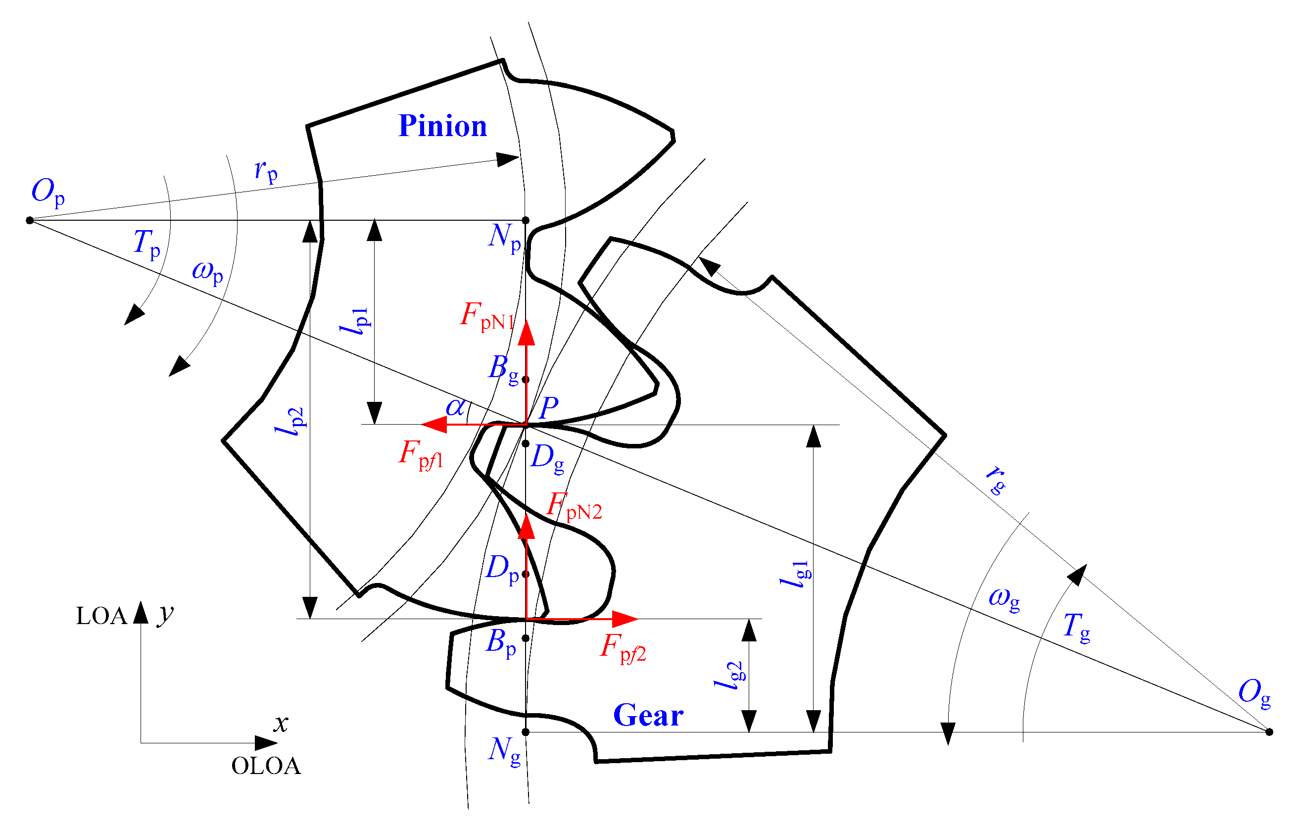
The engagement process of a spur gear pair is analyzed on a rigid system, which is shown in Figure 1. The tooth of the driving wheel (pinion) contacts the mating tooth of the driven one (gear) along the action line NpNg, which is the inner common tangent of two base circles. Due to the meshing characteristics of involute gear, the actual effective action line is BpBg, limited by each addendum circle [25]. Dp and Dg are the critical points of the meshing area of single and double teeth. P is the pitch point where the relative sliding speed between the tooth surfaces reverses, resulting in an inversive direction of the friction force. Based on the Coulomb friction law, the friction forces on pinion () and gear () in the meshing tooth pairs changing in time can be described as:
where i is equal to 1 and 2, representing single-tooth and double-tooth engagement areas, respectively. Theoretically, it is incorporated with the effects of both dry-contact and lubricant friction. However, lubricant friction has very minor impact on gear-pair torsional behaviors and the predicted motions are not prominent though different friction expressions [8,26]. Thus, a constant is still used in the current paper. is the direction coefficient of tooth friction, expressed by:
where “sgn” and “mod” are the sign and modulus functions, as defined in [8,27,28]. , , and are individually the involute outspread angles at points P, Bg, and Dp.
The friction arms of pinion and gear with ith tooth pair can be represented by:
where are the involute outspread angles at point Dg and is the pressure angle at the pitch point.
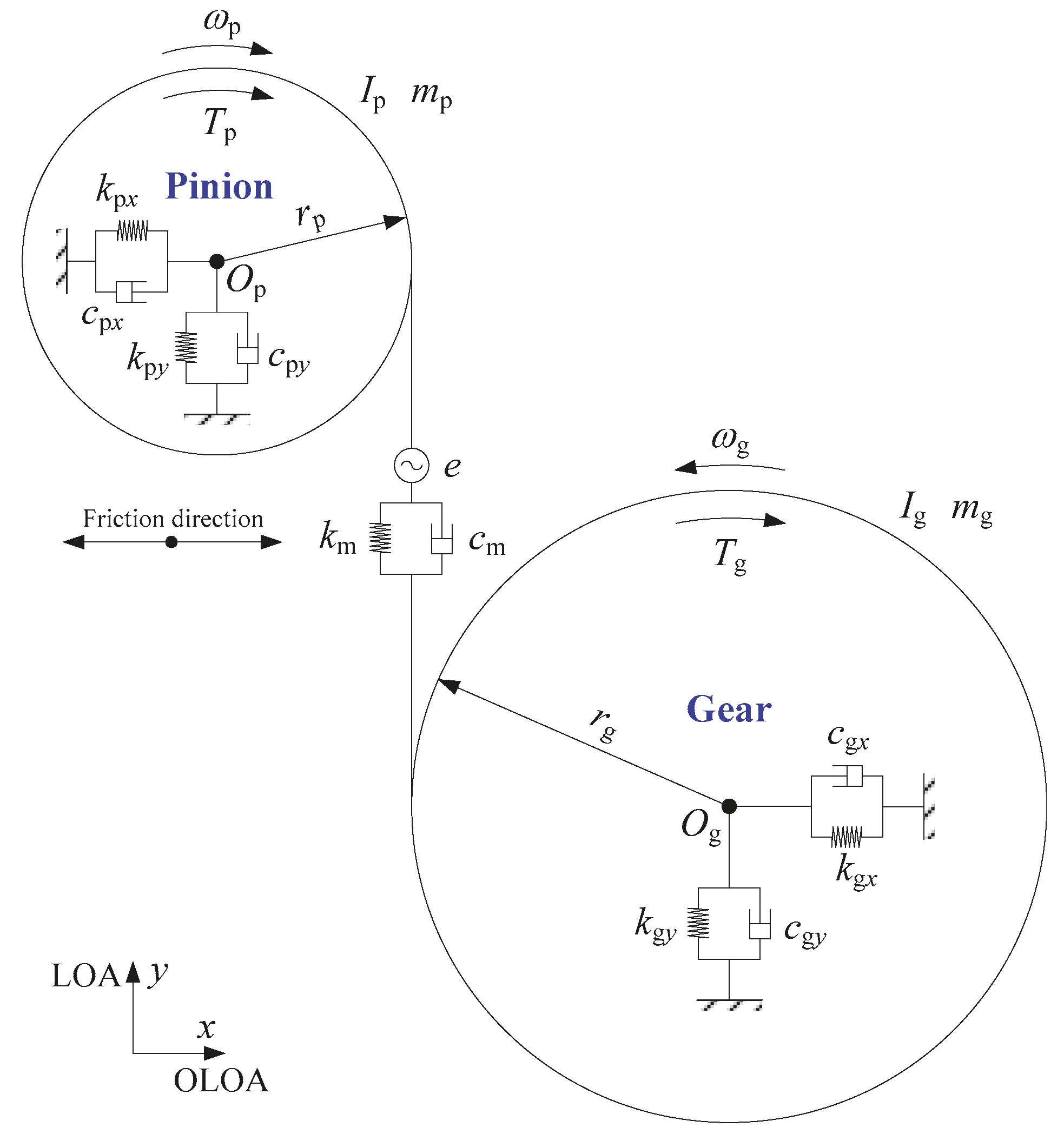
By simplifying the realistic gear system into a mass–spring damping system, a lumped parameter dynamic model having six-DOF (one rotational and two translational for each gear disc) is built [29]. The model schematic diagram with the time-varying mesh stiffness, transmission error, backlash, and friction force is shown in Figure 2, where the x- and y-axes are individually parallel to the off-line of action (OLOA) and line of action (LOA) directions of the gear pair. It is composed of a spur gear pair with masses (,), moments of inertia (,), and base circle radii (,), and the two gears are supported on roller bearings.
Both the torsional and transversal motions in the system are considered in the proposed nonlinear dynamic model. In light of the second Newtonian law, the equations of motion in the x, y, and θ directions for the pinion and gear can be individually formulated as follows:
where an overdot means differentiation with respect to time t.
The damping mechanisms in the gear mesh and bearings are assumed to have a linear feature, so the meshing forces are described in the following form:
where is the time-varying mesh stiffness, which will be discussed in Section 3. is the mesh damping which is proportional to the integral average stiffness and can be evaluated approximately using the following equation [23,30]:
where is the damping ratio (0.03–0.17).
The nonlinear displacement function can be expressed as the following:
where b is half of the total gear backlash. is the relative displacement along the LOA, which is also known as the dynamic transmission error (DTE), defined by:
where denotes the static transmission error (STE). It can commonly be approximated as a harmonic function:
where is the fundamental frequency of STE, .
The dynamic equations mentioned above contain time-varying mesh stiffness, friction, backlash, and static transmission error, which causes the strong nonlinear problem with parametric excitation in the system. A fourth- to fifth-order Runge–Kutta algorithm with a fixed time-step () is performed to numerically integrate these coupled nonlinear differential formulas [31]. The total integration time is supposed to be . Thus, the transient motion can be eliminated and the steady-state forced response can be gained.
3. Calculation of Time Varying Mesh Stiffness
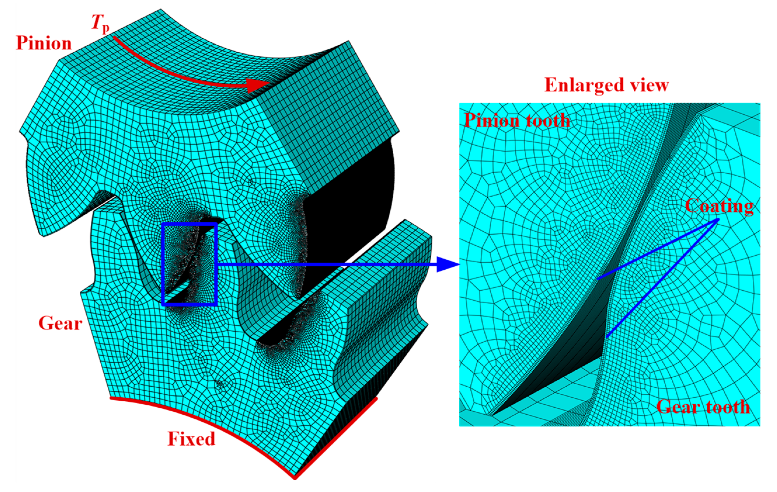
To find the connection between the rectilinear and the torsional mesh stiffness for gears, a method from [15,18] by using FE method is introduced. The current numerical calculations are performed via FE analysis code ABAQUS under a quasistatic condition. Table 1 lists parameters of a pair of Forschungsstelle für Zahnräder und Getriebebau (FZG) standard gear. The bore diameters of the pinion and gear are 45 and 65 mm, respectively. Since the contact ratio is 1.33, the three meshing teeth pairs of the FE model are applied to calculate the mesh stiffness. In order to decrease the element number in the model and reduce the calculation workload, it is necessary to refine the mesh locally. As seen in Figure 3, the gear-bore surface is fixed, and a torque is applied on the body of the pinion. There are 302,075 linear hexahedral elements of type C3D8R in the model. The total number of nodes is 380,284, and the average aspect ratio of the elements is 5.59. The gear and pinion surfaces are guaranteed to touch each other at any time. The thickness of the gear coating is 55 μm [32], and the coating is perfectly bonded on the gear substrate. The coefficient of friction (COF) between the coated gear surfaces is . The value of COF has been experimentally estimated and described afterwards.
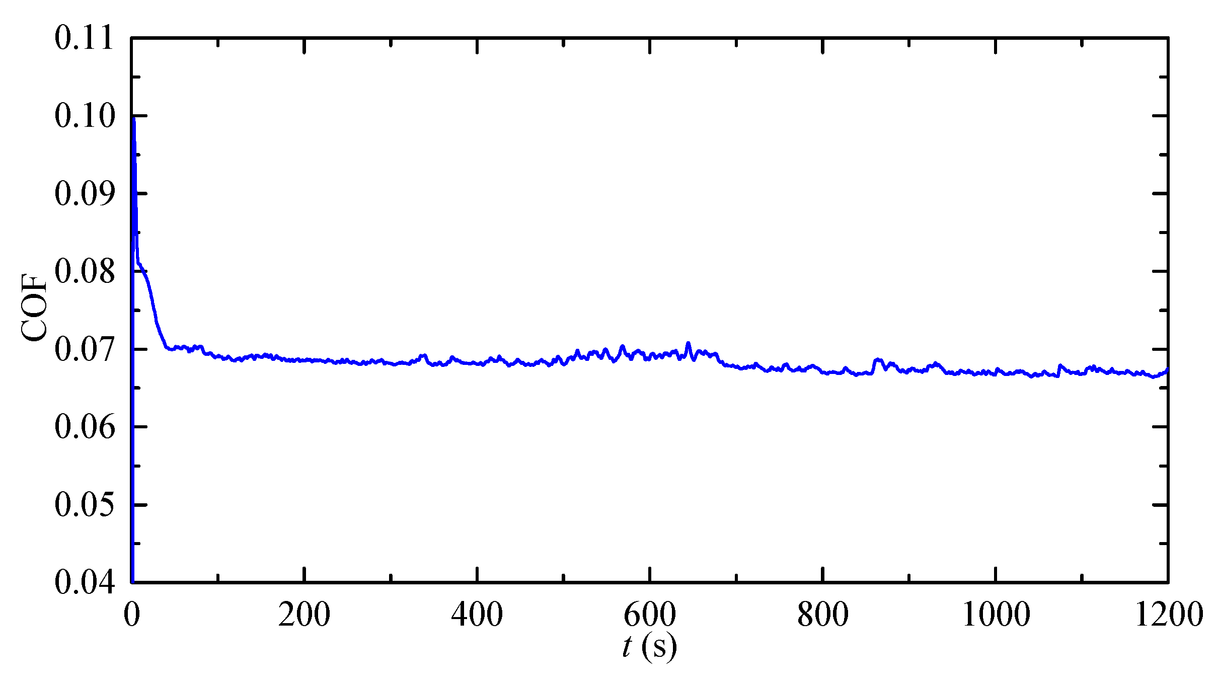
The material of the gear substrate is 20CrMnTi manufactured by Shandong Iron and Steel Company Ltd. Laiwu Company, China. Herein, a friction-reducing coating named diamond-like carbon (DLC), prepared by Southwest Institute of Physics, Mianyang, China, is deposited on the gear surfaces. Mechanical properties of the substrate and coating materials are shown in Table 2. For a DLC coating, the multiple variety of its structures as well as its diamond bond (sp3) and graphitic bond (sp2) content lead to a diversity of mechanical properties. Its elastic modulus fluctuates from 60 to 650 GPa [33]. To get the COF, the test is performed on a four-ball tribometer [34] using GL-5 heavy-duty extreme pressure gear oil (85w-90) as the lubricant. The friction curve of the DLC-coated sample is shown in Figure 4. It can be found that the COF during the stabilization period is individually about 0.067, which is imported into the above numerical calculation as a constant.
The angular deflections of the measurement points on the end surface circle of the pinion bore are obtained. The angular displacement of the pinion body is denoted by the minimal angular deflection . The rectilinear mesh stiffness can be evaluated as follows:
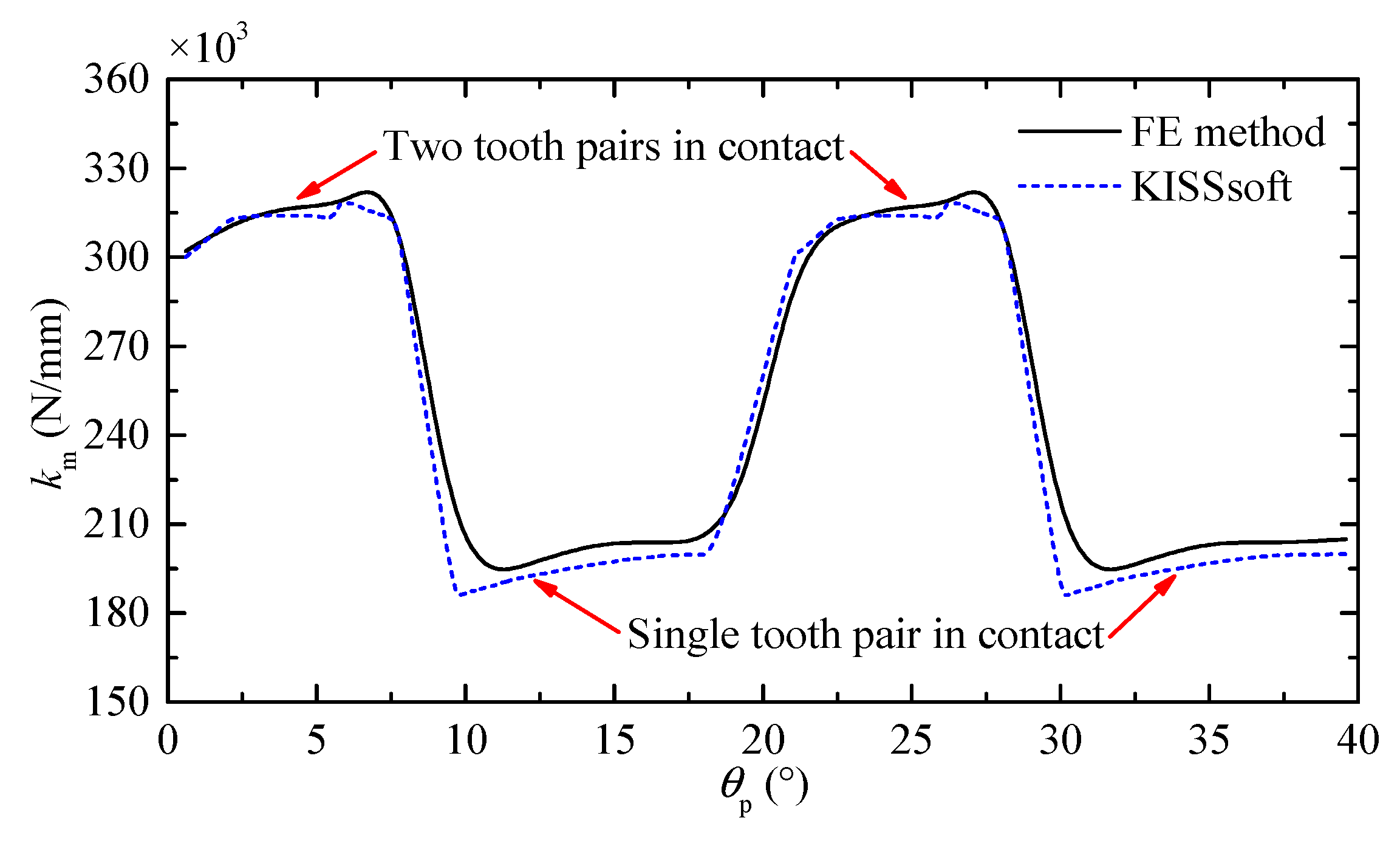
The time-varying mesh stiffness is calculated by selecting 20 meshing points (evenly distributed) from the tooth root to top. To verify the correctness of the current FE method, its result is compared with that of the commercial software KISSsoft (Gleason Company in Bubikon, Switzerland) [10]. It can be seen from Figure 5 that the two groups of results have good accuracy and coincide with each other.
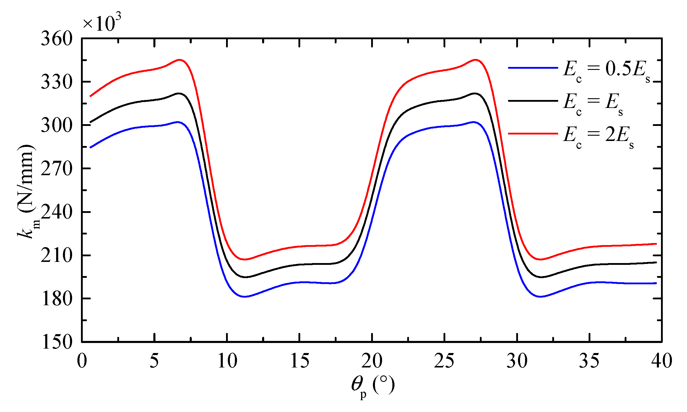
The curve-fitted plot of mesh stiffness variation along with the rotation angle is evinced in Figure 6. The meshing process of the gear pair inevitably appears to be alternating single and double teeth meshing. It is observed that the gear-mesh stiffness rises with the increase of coating elastic modulus. The main cause is that the deformation of the stiff coating is smaller than that of the soft one under the same load. Moreover, due to the influence of the substrate, when the coating elastic modulus is doubled, the mesh stiffness is not doubled, but the increase in amplitude is approximately the same.
4. Analysis of the Nonlinear Dynamic Responses
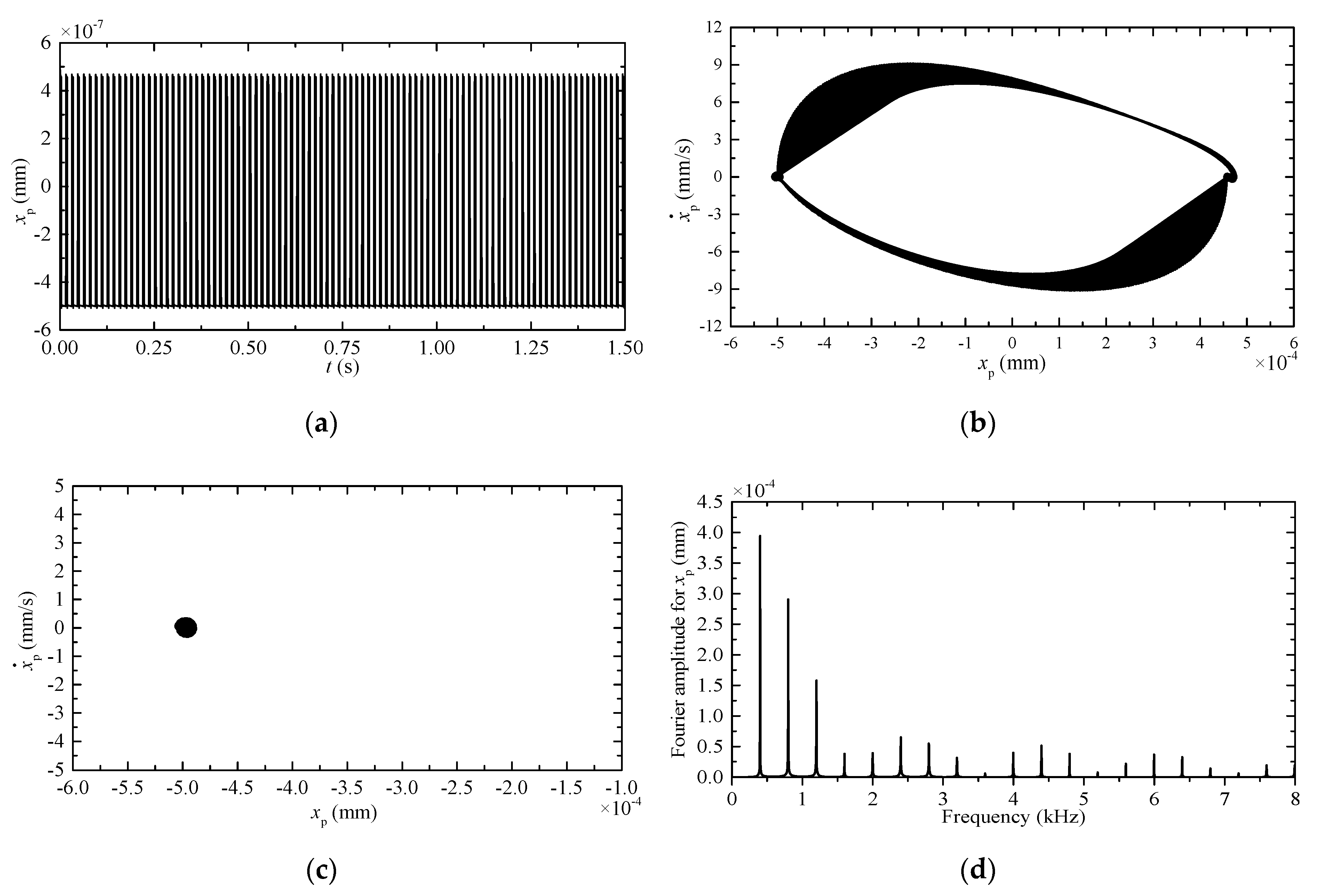
The main parameters in the current dynamic model are cited from [27], which are shown in Table 3. The present section describes the influence of coating on the nonlinear dynamic responses. It is a fact that the gear transmission system may exhibit multiperiod, quasiperiod, and chaos motion. To demonstrate the dynamic behaviors more visibly, different diagrams, such as the time-history curve, phase curve, Poincare map, and FFT (fast Fourier transform) spectrum, are shown as follows.
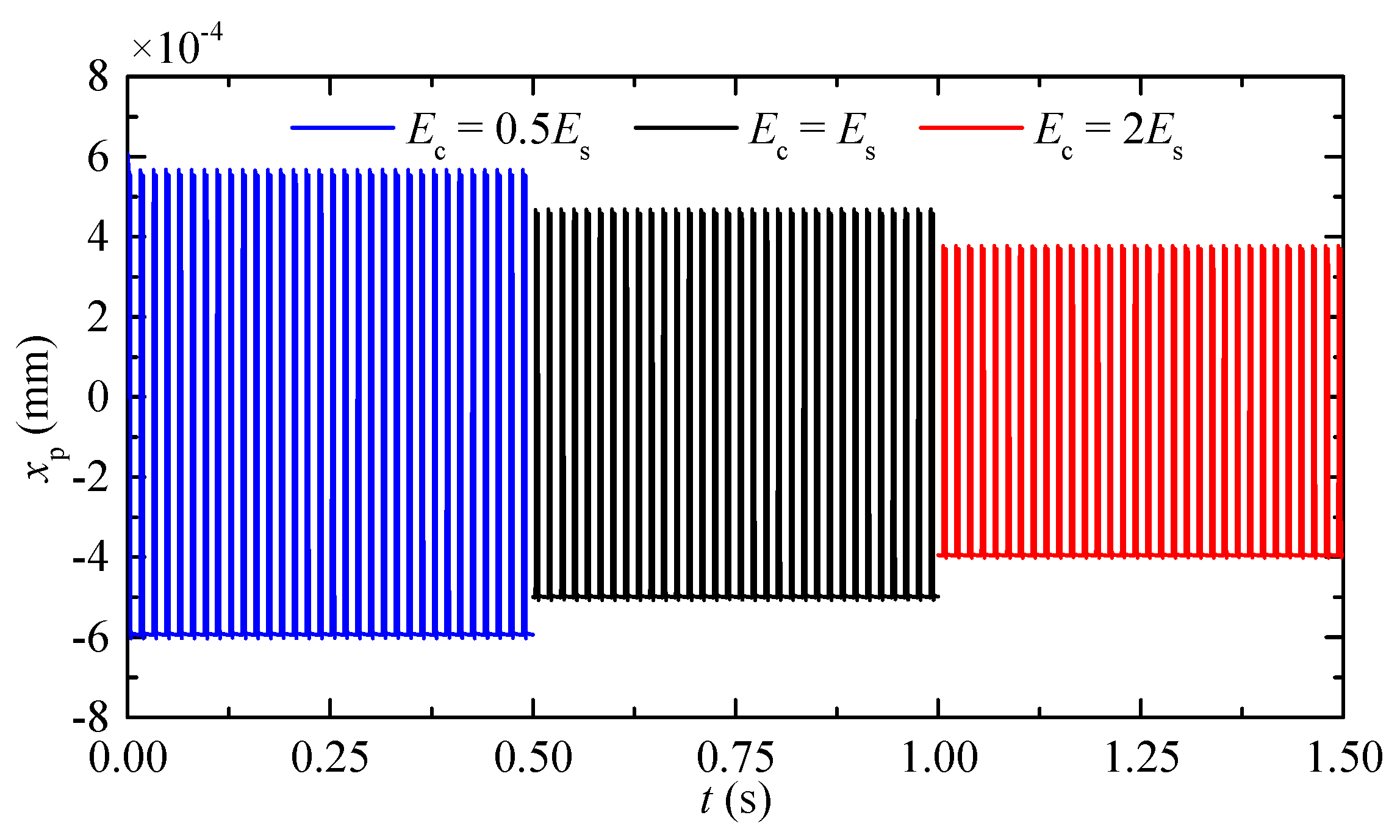
For the case of an uncoated gear pair (), it can be found from Figure 7a that the vibration displacement of the driving wheel along OLOA is symmetrical about , with quasiperiod characteristic, and difference between each cycle is small. The phase diagram (Figure 7b) is a two-piece space zone composed of several closed curves, some narrow and some wide, and approximately symmetrical about the center point. On the Poincare map (Figure 7c), the phase points gather in a small area, and the system tends toward a single periodic response. As shown in Figure 7d, the spectral lines of the spectrum map are distributed discretely on the points of the combined frequency. There are many superharmonic components in the system, and the amplitude components of the first three harmonic frequencies are higher. From Figure 8, we can find that the vibration amplitude along OLOA decreases with the growth of the coating elastic modulus.
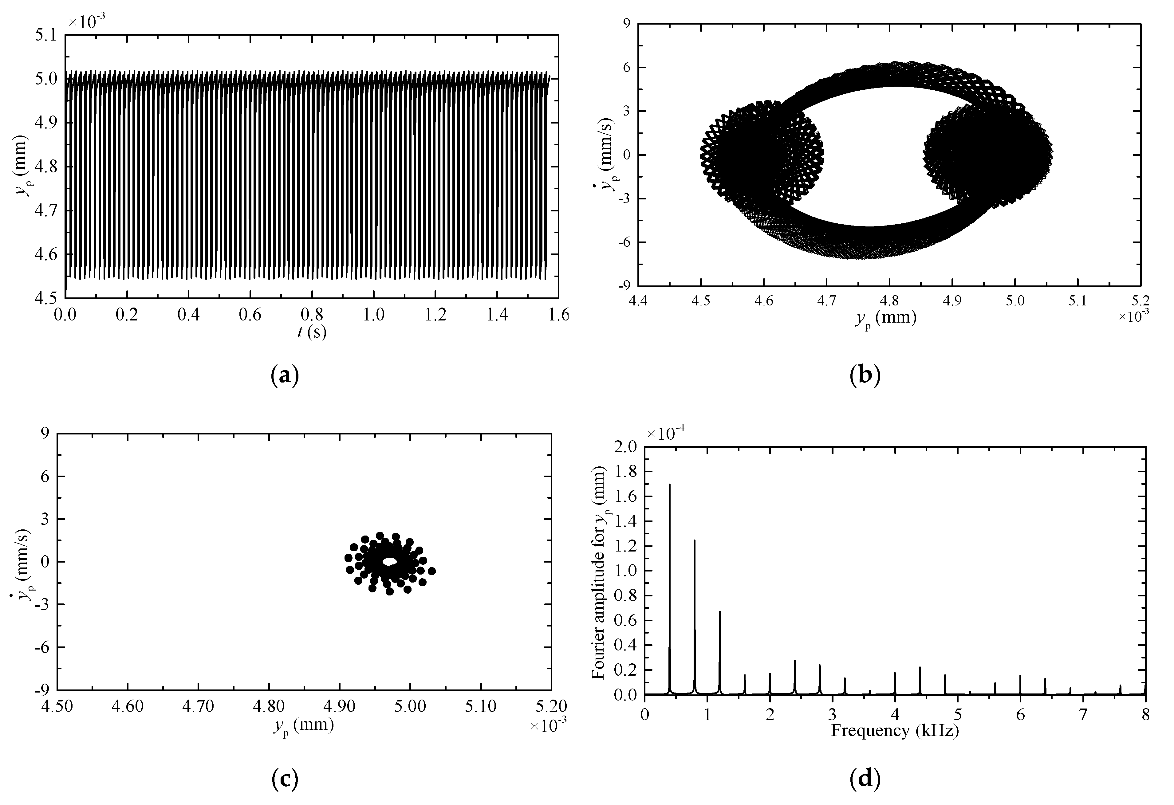
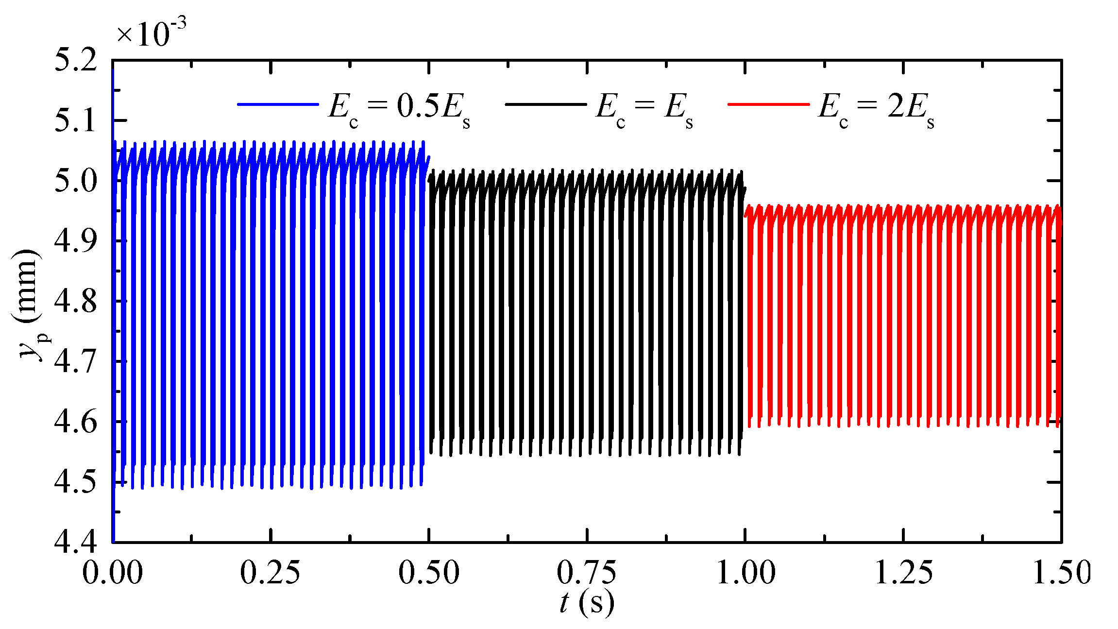
Figure 9 shows the time-history curve, phase curve, Poincare map, and FFT spectrum of the driving gear along LOA. It is manifest from the time-history curve that the vibration displacement along LOA fluctuates around 4.8 μm. Comparing Figure 9a with Figure 7a, the peak vibration amplitude along LOA is larger than that along the OLOA. The main reason is that the meshing force along LOA is greater than the friction along OLOA. The phase curve is a banded area which is neither repeated nor closed in the space, and it is clustered and distributed in a circular shape on both sides. It can be seen from the Poincare map that the phase points are radially distributed, but concentrated in a very narrow area, which shows that the response of the driving wheel along LOA is a one-period motion. Figure 9c demonstrates that the system also has many superharmonic components. Similar to Figure 8, Figure 10 exhibits that the vibration amplitude along LOA decreases with the increase in the coating elastic modulus.
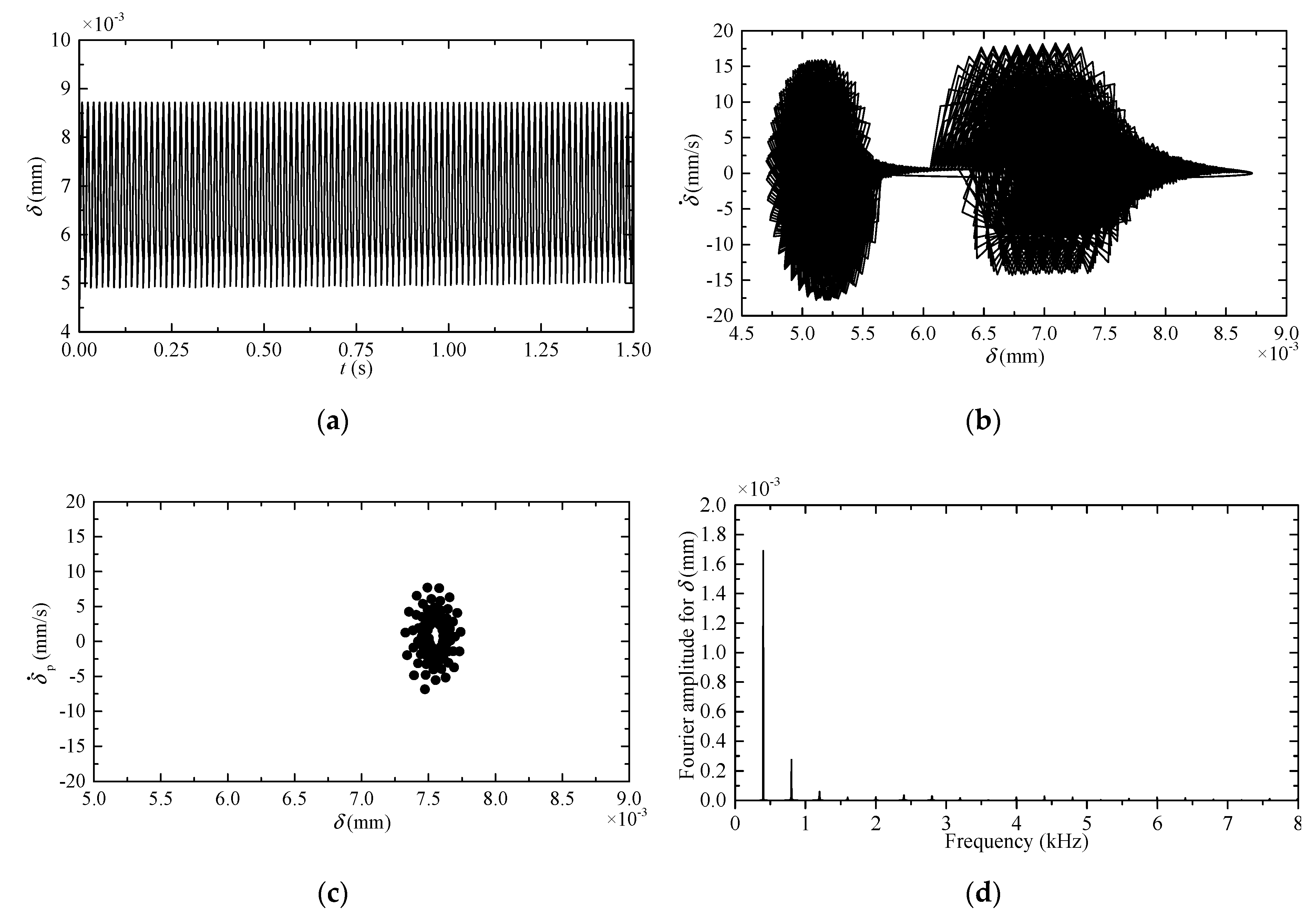
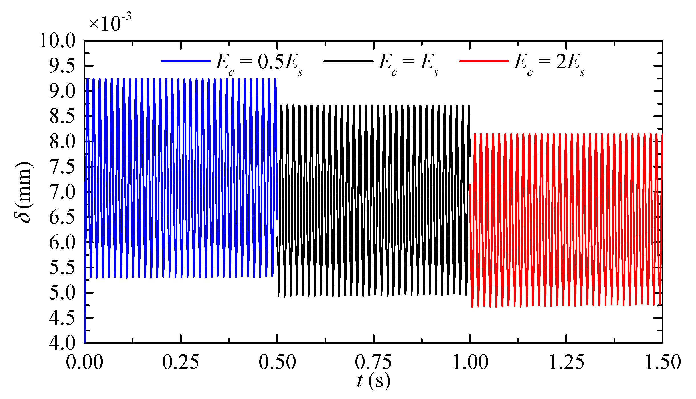
As shown in Figure 11, the DTE fluctuates between 4.5 and 9 μm. The phase diagram shows two concentrated areas, continuous but not repeated. According to the Poincare map, the system is still regarded as one-period motion. As seen from the FFT spectrum, the amplitudes of the first and second frequencies are larger, while the amplitudes of the remaining components are smaller. Figure 12 shows the DTE curve of coated gear models with different elastic moduli. When the coating elastic modulus increases, the DTE of the gear pair decreases as a whole.
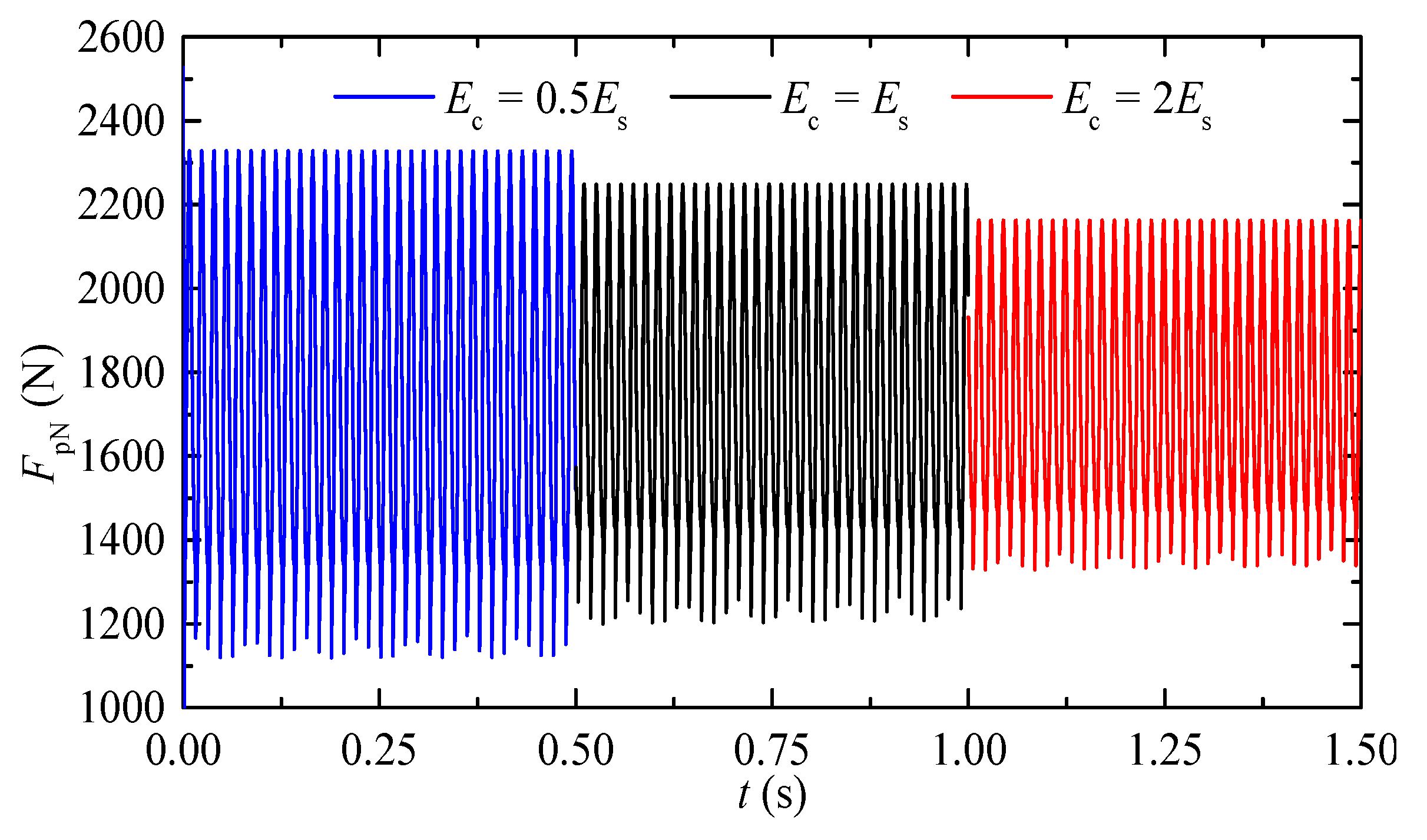
The dynamic meshing forces of coated gear pairs are influenced by the DTE and mesh stiffness based on Equation (5). Meshing forces under different coating elastic moduli are shown in Figure 13. The dynamic meshing force fluctuates around 1750 N. Its amplitude decreases with the increase of coating elastic modulus.
Meanwhile, the dynamic analysis method of the cracked gear can be applied to the coated gear, because both the crack and coating affect the time-varying mesh stiffness. Under the same external load, coatings with different elastic moduli have different time-varying mesh stiffness (Figure 6). The mesh stiffness decreases with the increased length of the tooth root crack [25,31]. It is found from [17] that the amplitude of the vibration displacement declines with the increase of mesh stiffness, which agrees well with the result of the current study (Figure 8 and Figure 10). From [35], the amplitude of DTE increases greatly when the impact of a crack on a gear body is involved. It verifies the law of the effect of the coating elastic modulus on DTE in the present work (Figure 12). Chen et al. [36] demonstrated that the tooth root crack could bring serious oscillations to the gear dynamic meshing force. This means that the fluctuation situation of the dynamic meshing force becomes more severe with the decrease of mesh stiffness, which is consistent with the conclusion of the research (Figure 13).
5. Conclusions
The nonlinear dynamic characteristic of a DLC-coated gear transmission system is analyzed by using a numerical integration approach. The effect of the coating elastic modulus on the dynamic response is investigated. Several illustrative numerical cases are introduced. According to the results, the following conclusions are put forward.
Under the given operating condition, the dynamic characteristic of a gear transmission system tends toward a one-period state, and there are many superharmonic components in the system. With the increase of coating elastic modulus, the gear-mesh stiffness and damping increase. The amplitudes of vibration displacements and velocities along OLOA and LOA decrease, respectively. Also, the oscillating curves of DTE move down as a whole. Moreover, increasing the coating elastic modulus can effectively reduce the amplitude of dynamic meshing force. It indicates that compared with softer coatings, stiffer ones can properly improve the transmission performance of the coated gear system.
Author Contributions
Conceptualization, Y.X. and J.L.; Methodology, Y.X. and L.F.; Software, Y.X. and L.F.; Validation, Y.X. and M.K.; Formal Analysis, J.L.; Investigation, M.K.; Resources, X.X.; Data Curation, Y.X.; Writing—Original Draft Preparation, L.F.; Writing—Review and Editing, Y.X.; Visualization, W.S.; Supervision, W.S.; Project Administration, Y.X.; Funding Acquisition, Y.X. All authors have read and agreed to the published version of the manuscript.
Funding
The research was funded by the National Natural Science Foundation of China (No. 51905204), the Hubei Provincial Natural Science Foundation of China (No. 2018CFB227), and the Fundamental Research Funds for the Central Universities (No. 2662017QD003).
Acknowledgments
The authors would like to acknowledge the Southwest Institute of Physics (P.R. China) for the preparation of the coatings.
Conflicts of Interest
The authors declare no conflict of interest. The funders had no role in the design of the study; in the collection, analyses, or interpretation of data; in the writing of the manuscript, or in the decision to publish the results.
Nomenclature
| half of total gear backlash | mass of pinion | ||
| radial damping in x direction of pinion | mass of gear | ||
| radial damping in y direction of pinion | base circle radius of pinion | ||
| radial damping in x direction of gear | base circle radius of gear | ||
| radial damping in y direction of gear | translational displacement of pinion along OLOA | ||
| mesh damping | translational displacement of pinion along LOA | ||
| STE | translational displacement of gear along OLOA | ||
| amplitude of STE | translational displacement of gear along LOA | ||
| time | angular displacement of pinion | ||
| drive torque applied on pinion | angular displacement of gear | ||
| brake torque applied on gear | tooth number of pinion | ||
| friction force of ith tooth pair on pinion | tooth number of gear | ||
| friction force of ith tooth pair on gear | direction coefficient of tooth friction | ||
| meshing force of ith tooth pair on pinion | COF of gear pair | ||
| meshing force of ith tooth pair on gear | pressure angle at pitch point | ||
| nonlinear displacement function | involute outspread angle at point j | ||
| moment of inertia of pinion | minimal angular deflection of pinion | ||
| moment of inertia of gear | phase angle of STE | ||
| radial stiffness in x direction of pinion | angular speed of pinion | ||
| radial stiffness in y direction of gear | angular speed of gear | ||
| radial stiffness in x direction of pinion | fundamental frequency of STE | ||
| radial stiffness in y direction of gear | substrate elastic modulus | ||
| time-varying mesh stiffness | coating elastic modulus | ||
| integral average stiffness | tooth face width | ||
| friction arm of pinion with ith tooth pair | DTE | ||
| friction arm of gear with ith tooth pair | damping ratio |
References
- Feng, L.; Wang, Z.; Shen, W. Effects of complex graphite-like carbon coating on gear vibration noise. Results Phys. 2019, 12, 1495–1499. [Google Scholar] [CrossRef]
- Liu, H.; Liu, H.; Zhu, C.; Wei, P.; Tang, J. Tribological behavior of coated spur gear pairs with tooth surface roughness. Friction 2019, 7, 117–128. [Google Scholar] [CrossRef] [Green Version]
- Bobzin, K.; Brögelmann, T.; Stahl, K.; Stemplinger, J.P.; Mayer, J.; Hinterstoißer, M. Influence of wetting and thermophysical properties of diamond-like carbon coatings on the frictional behavior in automobile gearboxes under elasto-hydrodynamic lubrication. Surf. Coat. Technol. 2015, 284, 290–301. [Google Scholar] [CrossRef]
- Yi, Y.; Huang, K.; Xiong, Y.; Sang, M. Nonlinear dynamic modelling and analysis for a spur gear system with time-varying pressure angle and gear backlash. Mech. Syst. Signal Process. 2019, 132, 18–34. [Google Scholar] [CrossRef]
- Wang, J.; Zhang, J.; Yao, Z.; Yang, X.; Sun, R.; Zhao, Y. Nonlinear characteristics of a multi-degree-of-freedom spur gear system with bending-torsional coupling vibration. Mech. Syst. Signal Process. 2019, 121, 810–827. [Google Scholar] [CrossRef]
- Wang, J.; He, G.; Zhang, J.; Zhao, Y.; Yao, Y. Nonlinear dynamics analysis of the spur gear system for railway locomotive. Mech. Syst. Signal Process. 2017, 85, 41–55. [Google Scholar] [CrossRef]
- Liu, L.; Xiong, Y.P. Dynamic characteristics of torus involute gear drive. J. Braz. Soc. Mech. Sci. Eng. 2017, 39, 3807–3819. [Google Scholar] [CrossRef] [Green Version]
- Liu, F.; Jiang, H.; Yu, X. Dynamic behavior analysis of spur gears with constant & variable excitations considering sliding friction influence. J. Mech. Sci. Technol. 2016, 30, 5363–5370. [Google Scholar]
- Ma, H.; Pang, X.; Zeng, J.; Wang, Q.; Wen, B. Effects of gear crack propagation paths on vibration responses of the perforated gear system. Mech. Syst. Signal Process. 2015, 62, 113–128. [Google Scholar] [CrossRef]
- Marafona, J.D.; Marques, P.M.; Martins, R.C.; Seabra, J.H. Towards constant mesh stiffness helical gears: The influence of integer overlap ratios. Mech. Mach. Theory 2019, 136, 141–161. [Google Scholar] [CrossRef]
- Zhou, X.; Shao, Y.; Lei, Y.; Zuo, M. Time-varying meshing stiffness calculation and vibration analysis for a 16dof dynamic model with linear crack growth in a pinion. J. Vib. Acoust. 2011, 134. [Google Scholar] [CrossRef]
- ISO Standard 6336-1: Calculation of Load Capacity of Spur and Helical Gears—Part 1: Basic Principles, Introduction and General Influence Factors; The international organization for standardization: Geneva, Switzerland, 2019.
- Chaari, F.; Fakhfakh, T.; Haddar, M. Analytical modelling of spur gear tooth crack and influence on gearmesh stiffness. Eur. J. Mech. Solids 2009, 28, 461–468. [Google Scholar] [CrossRef]
- Chang, L.; Liu, G.; Wu, L. A robust model for determining the mesh stiffness of cylindrical gears. Mech. Mach. Theory 2015, 87, 93–114. [Google Scholar] [CrossRef]
- Howard, I.; Jia, S.; Wang, J. The dynamic modelling of a spur gear in mesh including friction and a crack. Mech. Syst. Signal Process. 2001, 15, 831–853. [Google Scholar] [CrossRef]
- Ma, H.; Li, Z.; Feng, M.; Feng, R.; Wen, B. Time-varying mesh stiffness calculation of spur gears with spalling defect. Eng. Fail. Anal. 2016, 66, 166–176. [Google Scholar] [CrossRef]
- Wan, Z.; Cao, H.; Zi, Y.; He, W.; He, Z. An improved time-varying mesh stiffness algorithm and dynamic modeling of gear-rotor system with tooth root crack. Eng. Fail. Anal. 2014, 42, 157–177. [Google Scholar] [CrossRef]
- Liang, X.; Zhang, H.; Zuo, M.J.; Qin, Y. Three new models for evaluation of standard involute spur gear mesh stiffness. Mech. Syst. Signal Process. 2018, 101, 424–434. [Google Scholar] [CrossRef]
- De Souza, S.L.; Caldas, I.L.; Viana, R.L.; Balthazar, J.M. Sudden changes in chaotic attractors and transient basins in a model for rattling in gearboxes. Chaos Solitons Fractals 2004, 21, 763–772. [Google Scholar] [CrossRef]
- Wei, J.; Gao, P.; Hu, X.; Sun, W.; Zeng, J. Effects of dynamic transmission errors and vibration stability in helical gears. J. Mech. Sci. Technol. 2014, 28, 2253–2262. [Google Scholar] [CrossRef]
- Omar, F.K.; Moustafa, K.A.; Emam, S. Mathematical modeling of gearbox including defects with experimental verification. J. Vib. Control 2012, 18, 1310–1321. [Google Scholar] [CrossRef]
- Parey, A.; El Badaoui, M.; Guillet, F.; Tandon, N. Dynamic modelling of spur gear pair and application of empirical mode decomposition-based statistical analysis for early detection of localized tooth defect. J. Sound Vib. 2006, 294, 547–561. [Google Scholar] [CrossRef]
- Mohammed, O.D.; Rantatalo, M.; Aidanpää, J.O. Dynamic modelling of a one-stage spur gear system and vibration-based tooth crack detection analysis. Mech. Syst. Signal Process. 2015, 54, 293–305. [Google Scholar] [CrossRef]
- Xiao, Y.Y.; Zou, M.J.; Shi, W.K.; Kang, M.L. Analysis of the surface/interface damage evolution behavior of a coating–substrate system under heavy-load elastohydrodynamic lubrication. Coatings 2019, 9, 642. [Google Scholar] [CrossRef] [Green Version]
- Luo, Y.; Baddour, N.; Liang, M. Effects of gear center distance variation on time varying mesh stiffness of a spur gear pair. Eng. Fail. Anal. 2017, 75, 37–53. [Google Scholar] [CrossRef]
- Liu, F.; Theodossiades, S.; Bergman, L.; Vakakis, A.; McFarland, D. Analytical characterization of damping in gear teeth dynamics under hydrodynamic conditions. Mech. Mach. Theory 2015, 94, 141–147. [Google Scholar] [CrossRef] [Green Version]
- Chen, Z.G.; Shao, Y.M.; Lim, T.C. Non-linear dynamic simulation of gear response under the idling condition. Int. J. Automot. Technol. 2012, 13, 541–552. [Google Scholar] [CrossRef]
- He, S.; Gunda, R.; Singh, R. Effect of sliding friction on the dynamics of spur gear pair with realistic time-varying stiffness. J. Sound Vib. 2007, 301, 927–949. [Google Scholar] [CrossRef]
- Kahraman, A.; Singh, R. Interactions between time-varying mesh stiffness and clearance non-linearities in a geared system. J. Sound Vib. 1991, 146, 135–156. [Google Scholar] [CrossRef]
- Amabili, M.; Rivola, A. Dynamic analysis of spur gear pairs: Steady-state response and stability of the sdof model with time-varying meshing damping. Mech. Syst. Signal Process. 1997, 11, 375–390. [Google Scholar] [CrossRef]
- Yang, Y.; Xia, W.; Han, J.; Song, Y.; Wang, J.; Dai, Y. Vibration analysis for tooth crack detection in a spur gear system with clearance nonlinearity. Int. J. Mech. Sci. 2019, 648–661. [Google Scholar] [CrossRef]
- Rübig, B.; Heim, D.; Forsich, C.; Dipolt, C.; Mueller, T.; Gebeshuber, A.; Kullmer, R.; Holecek, R.; Lugmair, C.; Krawinkler, M.; et al. Tribological behavior of thick DLC coatings under lubricated conditions. Surf. Coat. Technol. 2017, 314, 13–17. [Google Scholar] [CrossRef]
- Vetter, J. 60 years of DLC coatings: Historical highlights and technical review of cathodic arc processes to synthesize various DLC types, and their evolution for industrial applications. Surf. Coat. Technol. 2014, 257, 213–240. [Google Scholar] [CrossRef]
- Uflyand, I.E.; Zhinzhilo, V.A.; Burlakova, V.E. Metal-containing nanomaterials as lubricant additives: State-of-the-art and future development. Friction 2019, 7, 93–116. [Google Scholar] [CrossRef] [Green Version]
- Jiang, H.; Liu, F. Analytical models of mesh stiffness for cracked spur gears considering gear body deflection and dynamic simulation. Meccanica 2019, 54, 1889–1909. [Google Scholar] [CrossRef]
- Chen, Z.; Zhai, W.; Wang, K. Vibration feature evolution of locomotive with tooth root crack propagation of gear transmission system. Mech. Syst. Signal Process. 2019, 115, 29–44. [Google Scholar] [CrossRef]
Figure 1.
Meshing process of a spur gear transmission.

Figure 2.
Nonlinear dynamic model of a spur gear transmission.

Figure 3.
FE boundary conditions of the gear transmission system.

Figure 4.
The friction curve of the DLC-coated sample.

Figure 5.
Validation of gear-mesh stiffness.

Figure 6.
Gear mesh stiffness under different coating elastic moduli.

Figure 7.
The vibration response of pinion () along OLOA is analyzed by comparing the (a) time-history curve, (b) phase curve, (c) Poincare map, and (d) FFT spectrum.
Figure 7.
The vibration response of pinion () along OLOA is analyzed by comparing the (a) time-history curve, (b) phase curve, (c) Poincare map, and (d) FFT spectrum.

Figure 8.
Vibration displacements along OLOA under different coating elastic moduli.

Figure 9.
The vibration response of pinion () along LOA is analyzed by comparing the (a) time history curve, (b) phase curve, (c) Poincare map, and (d) FFT spectrum.
Figure 9.
The vibration response of pinion () along LOA is analyzed by comparing the (a) time history curve, (b) phase curve, (c) Poincare map, and (d) FFT spectrum.

Figure 10.
Vibration displacements along LOA under different coating elastic moduli.

Figure 11.
The dynamic transmission error (DTE) () is analyzed by comparing the (a) time-history curve, (b) phase curve, (c) Poincare map, and (d) FFT spectrum.
Figure 11.
The dynamic transmission error (DTE) () is analyzed by comparing the (a) time-history curve, (b) phase curve, (c) Poincare map, and (d) FFT spectrum.

Figure 12.
DTEs under different coating elastic moduli.

Figure 13.
Dynamic meshing forces under different coating elastic moduli.


Table 1.
Geometrical parameters of the gear pair.
| Parameter | Pinion | Gear |
|---|---|---|
| Tooth number | 16 | 24 |
| Modulus (mm) | 4.5 | 4.5 |
| Center distance (mm) | 91.5 | |
| Pressure angle (°) | 20 | |
| Tooth face width (mm) | 20 | |
| Profile shift | +0.853 | −0.5 |
| Addendum diameter (mm) | 88.77 | 112.50 |
| Contact ratio | 1.33 | |
Table 2.
Mechanical properties of the substrate and coating materials.
| Parameter | 20CrMnTi Substrate | DLC Coating |
|---|---|---|
| Elastic modulus (GPa) | 210 | 105, 210, 420 |
| Poisson’s ratio | 0.3 | 0.3 |
Table 3.
Main parameters in dynamic model.
| Parameter | Pinion | Gear |
|---|---|---|
| Mass (kg) | 0.676 | 1.084 |
| Moment of inertia (kg·m²) | 4.07 × 10⁻⁴ | 1.168 × 10⁻³ |
| Angular speed (rad/s) | 50π | 50π/1.5 |
| Torque (N·m) | 60 | 90 |
| Support stiffness (N/m) | 6.56 × 10⁷ | 6.56 × 10⁷ |
| Support damping (N·s/m) | 1.8 × 10⁵ | 1.8 × 10⁵ |
| Amplitude of static transmission error (STE) (μm) | 10 | |
| Backlash (μm) | 20 | |
| Damping ratio | 0.07 | |
© 2020 by the authors. Licensee MDPI, Basel, Switzerland. This article is an open access article distributed under the terms and conditions of the Creative Commons Attribution (CC BY) license (http://creativecommons.org/licenses/by/4.0/).
Share and Cite
MDPI and ACS Style
Xiao, Y.; Fu, L.; Luo, J.; Shi, W.; Kang, M. Nonlinear Dynamic Characteristic Analysis of a Coated Gear Transmission System. Coatings 2020, 10, 39. https://0-doi-org.brum.beds.ac.uk/10.3390/coatings10010039
AMA Style
Xiao Y, Fu L, Luo J, Shi W, Kang M. Nonlinear Dynamic Characteristic Analysis of a Coated Gear Transmission System. Coatings. 2020; 10(1):39. https://0-doi-org.brum.beds.ac.uk/10.3390/coatings10010039
Chicago/Turabian StyleXiao, Yangyi, Liyang Fu, Jing Luo, Wankai Shi, and Minglin Kang. 2020. "Nonlinear Dynamic Characteristic Analysis of a Coated Gear Transmission System" Coatings 10, no. 1: 39. https://0-doi-org.brum.beds.ac.uk/10.3390/coatings10010039
Note that from the first issue of 2016, this journal uses article numbers instead of page numbers. See further details here.