Article

CoCrFeNi High-Entropy Alloy Thin Films Synthesised by Magnetron Sputter Deposition from Spark Plasma Sintered Targets

1
Institute of Physics, Faculty of Natural Sciences, TU Chemnitz, 09126 Chemnitz, Germany
2
Institute of Materials Science and Engineering, Faculty of Mechanical Engineering, TU Chemnitz, 09125 Chemnitz, Germany
3
Center for Materials, Architectures and Integration of Nanomembranes (MAIN), TU Chemnitz, 09126 Chemnitz, Germany
4
Institute of Ion Beam Physics and Materials Research, Helmholtz-Zentrum Dresden-Rossendorf, Bautzner Landstrasse 400, 01328 Dresden, Germany
*
Authors to whom correspondence should be addressed.
Submission received: 15 March 2021 / Revised: 12 April 2021 / Accepted: 15 April 2021 / Published: 17 April 2021

Abstract

:
Two magnetron sputter targets of CoCrFeNi High-Entropy Alloy (HEA), both in equal atomic ratio, were prepared by spark plasma sintering. One of the targets was fabricated from a homogeneous HEA powder produced via gas atomisation; for the second target, a mixture of pure element powders was used. Economic benefits can be achieved by mixing pure powders in the intended ratio in comparison to the gas atomisation of the specific alloy composition. In this work, thin films deposited via magnetron sputtering from both targets are analysed. The surface elemental composition is investigated by X-ray photoelectron spectroscopy, whereas the bulk stoichiometry is measured by X-ray fluorescence spectroscopy. Phase information and surface microstructure are investigated using X-ray diffraction and scanning electron microscopy, respectively. It is demonstrated that the stoichiometry, phase composition and microscopic structure of the as-deposited HEA thin films are almost identical if the same deposition parameters are used.

1. Introduction

Compositionally complex alloys were defined and reported for the first time by Cantor et al. [1] and are often referred to as High-Entropy Alloys (HEAs) [2,3]. In this class of materials, an equimolar or near-equimolar mixture of four or more elements is created, in contrast to common alloys, with one primary element, e.g., steels [1]. It is predicted that the high configurational entropy and low mixing enthalpy of such a compound will lead to a preferential formation of single-phase solid solutions [2]. Extensive research on this new class of materials revealed numerous remarkable properties, like high wear resistance [4], high corrosion resistance [5], or high hardness [6,7]. A significant change in various physical and mechanical properties as a consequence of variation in the elemental composition has been reported for different HEAs [2]. Like most metals and alloys, HEAs can be fabricated and processed in many ways. A suitable method to form homogeneous, large area thin films is magnetron sputtering. HEAs have already been successfully sputtered from mosaic targets [8,9], loosely pressed powder targets [10,11,12] or sintered targets [13,14,15]. However, to the best of our knowledge, a direct comparison of HEA films fabricated from two differently prepared sputter targets used in the same system under equal conditions has not been reported so far. In the present work, the fabrication of sputter targets sintered from a homogeneous CoCrFeNi HEA powder prepared via gas atomisation and from an equimolar powder mixture of pure elements is described. The stoichiometry, phase composition and surface structure of the two targets and thin films prepared from each target via magnetron sputtering are analysed and compared.

2. Materials and Methods

The sputtering targets were produced by spark plasma sintering (SPS) in vacuum in an SPS KCE FCT-HP D 25-SI (FCT Systeme GmbH, Frankenblick, Germany) system. The sintering tool consists of two cylindrical pistons made of graphite, which are pressed against the powders from both sides inside a graphite mould. Graphite foils are used as a separator between the pistons and the powder. In this process, the powders were sintered to form discs with a diameter of 50   mm and a thickness of 5   mm . The pressure during sintering was kept constant at 50   MPa . After a heat-up time of 10   min , the sintering temperature of 1050   C was maintained for 5   min . Two different types of targets were sintered in order to compare the properties of the targets as well as of the coatings. The first target discussed in this work (”Alloytarget”) was produced using an alloy powder of CoCrFeNi (Nanoval GmbH, Berlin, Germany) with a grain size of 20–50 μm, which was produced by gas atomisation. Inside this powder, the alloying elements are expected to be distributed uniformly on a microscopic scale. A second target (”Blendtarget”) was produced using a blend of pure element powders with purity > 99.5 % and a particle size ranging between 20 and 74 μm, which were uniformed in a tumble mixer for 10   min prior to the sintering process. Due to this mixing process, a heterogeneous distribution of the pure elements on a microscopic scale was expected for the resulting macroscopically homogeneous target.
Both targets were used to prepare thin films of CoCrFeNi by DC magnetron sputtering on Si(100) and stainless-steel (type EN 1.4404) substrates. Before being mounted into the sputter chamber, the substrates were cleaned with isopropanol and acetone in an ultrasonic bath for 15   min each and rinsed with deionised water afterwards. In each sputter process, one substrate of each type was coated simultaneously. The deposition was carried out in an INOVAP CF503 system (INOVAP GmbH, Radeberg, Germany) with a base pressure of 5   ×   10 7   mbar . Prior to the depositions, the substrates were cleaned by radio-frequency (RF) etching in pure Ar atmosphere with a pressure of 1.5 Pa and an Ar-flow rate of 50   sccm for 5   min . The targets were presputtered before each deposition for 5   min in the same Ar atmosphere to remove contaminants from the target surface and to achieve a balance of the sputter rates for all elements. After that, the substrates were rotated towards the target and deposition took place for 60   min with a distance of 160   mm between substrate and sputtering target. We discuss four samples prepared using different sputtering power. The deposition parameters are summarised in Table 1. The thickness of the HEA thin films was measured using a Dektak 8.35 Profiler (Bruker Corporation, Billerica, MA, USA).
In order to investigate the surface stoichiometry, the as-sintered targets used for deposition as well as the HEA coatings were investigated using X-ray photoelectron spectroscopy (XPS). All presented XPS measurements were carried out at a base pressure of 2   ×   10 10   mbar using Al K α radiation ( 1486.6   eV ) from a Specs XR50M X-ray source monochromatised with a Specs Focus 500 monochromator and a Specs Phoibos 150 analyser (SPECS Surface Nano Analysis GmbH, Berlin, Germany). In order to reduce surface contamination, the samples were treated with Ar + bombardment for 15   min ( I emission = 10   mA , U   =   2.5   kV , p = 2   ×   10 7   mbar ). An angle of 40 with respect to the sample normal was used for the bombardment. Since XPS is only sensitive to the topmost few nm of a sample, X-ray fluorescence (XRF) measurements were conducted as well to get an insight into the bulk composition of all the specimens discussed. For the XRF measurements, a FISCHERSCOPE XRAY XAN spectrometer (HELMUT FISCHER GmbH, Sindelfingen, Germany) with an anode voltage of 30   kV , Ni-filter, and 0.6   mm collimator was used. With the help of the Fischer XAN-WinFTM 6.33 software, the elemental composition of the specimens was determined from spectra measured on six positions across the sample. To compare the phase composition of the HEA thin films and the used targets, X-ray diffraction (XRD) measurements were carried out with a Rigaku SmartLab 9 kW instrument equipped with a HyPix-3000 detector (Rigaku Corporation, Tokyo, Japan). All XRD data were obtained using Cu K α radiation ( 1.5406   Å ). The sputtering targets were measured in Bragg–Brentano geometry. For the thin films, a parallel beam measurement was been conducted in 2 θ / ω geometry, since it offers the potential to suppress the reflection of the Si substrate. The microscopic surface structure of the sputtered HEA thin films was investigated using a Nova NanoSEM 200 system (FEI, Hillsboro, Oregon, USA) with a voltage of 5   kV . Information about the grain structure was obtained with WsxM 4.0 [16]. The distribution of constituents in the sputtering targets was analysed by energy-dispersive X-ray spectroscopy (EDX) using an Ametek Genesis MK2 detector (EDAX Inc., Mahwah, NJ, USA).

3. Results and Discussion

We begin with an analysis of the sputtering targets. XPS survey spectra of both targets are shown in Figure 1. While all four of the expected HEA elements can be identified in the spectra of the pristine targets, it can be seen that the surface shows significant contamination with oxygen and carbon. Traces of nitrogen were detected in the case of the Alloytarget at E B = 398   eV . The amount of oxygen indicates a high level of surface oxidation and explains the comparably small metal core level signals. A strong reduction of the oxygen signal due to the Ar + bombarding can be noted, and likewise, the carbon and nitrogen contaminations almost vanish. The remaining carbon signal can be attributed to residuals from the graphite foils used in the sintering process. Due to ion implantation, weak signals of Ar2s at E B = 320   eV and Ar2p at E B = 243   eV were detected after the bombardment step. Subsequent repetition of this process for up to 45   min of total bombardment time did not lead to a further change of the oxygen signal. The stoichiometric ratio of the HEA elements remained unchanged even for higher bombardment times. The 2p core levels of the involved HEA elements Co, Cr, Fe and Ni were measured with higher resolution. The 2p 3 / 2 core level spectra of Cr, Fe and Ni, and the Co2p 1 / 2 line were fitted using an asymmetric Mahan peak shape for metallic components, and symmetric Voigt peaks for satellite features and multiplet split oxide components, as suggested by Biesinger et al. [17,18,19]. The presence of Ni auger lines in the region of the Fe2p and Co2p lines was taken into account as well. From a pure Ni specimen, the ratio of the Ni L 3 M 23 M 45 ( 1 P) and L 3 M 23 M 45 ( 3 P) Auger lines relative to the Ni2p 3 / 2 signal was obtained. By applying this ratio to the fitted Ni signal of each of the discussed specimens, it was possible to subtract the influence of the Ni Auger signals from the Fe2p 3 / 2 region. Since the Co2p 3 / 2 region is not only overlapping with the Ni L 3 M 23 M 23 signal but also partially with the L 3 M 45 M 45 Auger peak of iron, the Co2p 1 / 2 signal was used for stoichiometric calculations instead. The integrated intensities I of the HEA core level signals were corrected for their photoionisation cross sections σ taken from Scoffield [20] as well as the spectrometer transmission function T ( E kin ) and the electron inelastic mean free path λ ( E kin ) . With these values the corrected intensity I c can be calculated for element X using Equation (1).
I c , X = I X σ X · T X ( E kin ) · λ X ( E kin )
Relating the corrected intensities of the different elements can be used to obtain the samples stoichiometric composition. The same procedure was applied to the sputtered HEA thin films listed in Table 1. We note that the thickness of all sputtered films discussed here is > 700   nm , and therefore the influence of the substrate during XPS measurements can be neglected.
In Figure 2, the elemental composition measured by XPS and XRF is shown for both of the targets. The deviation of the XPS results from the expected equimolar stoichiometry is quite high, with values up to 5.7 % difference. In the case of the Alloytarget, the XRF results are much closer to the expectation than the XPS data, and the standard deviation is below 0.3 % for all elements, indicating a homogeneous equimolar bulk composition of the alloy target. Differences between both methods can partially be attributed to the influence of residual surface contaminations as well as a changed surface composition due to the Ar + bombardment step before XPS, which is known to have different yield for each element. While this is also true for the Blendtarget, both methods show a Ni content of circa 30 % , while the Cr and Co percentage is below expectations. Cr content values obtained from XRF vary in a range of 15%–25% for different positions across the target, resulting in a standard deviation of 3.7 % . In general, the deviation across the sample is much higher for the XRF measurements of the Blendtarget, which implies a more inhomogeneous elemental distribution most likely caused by the target fabrication from a powder mixture.
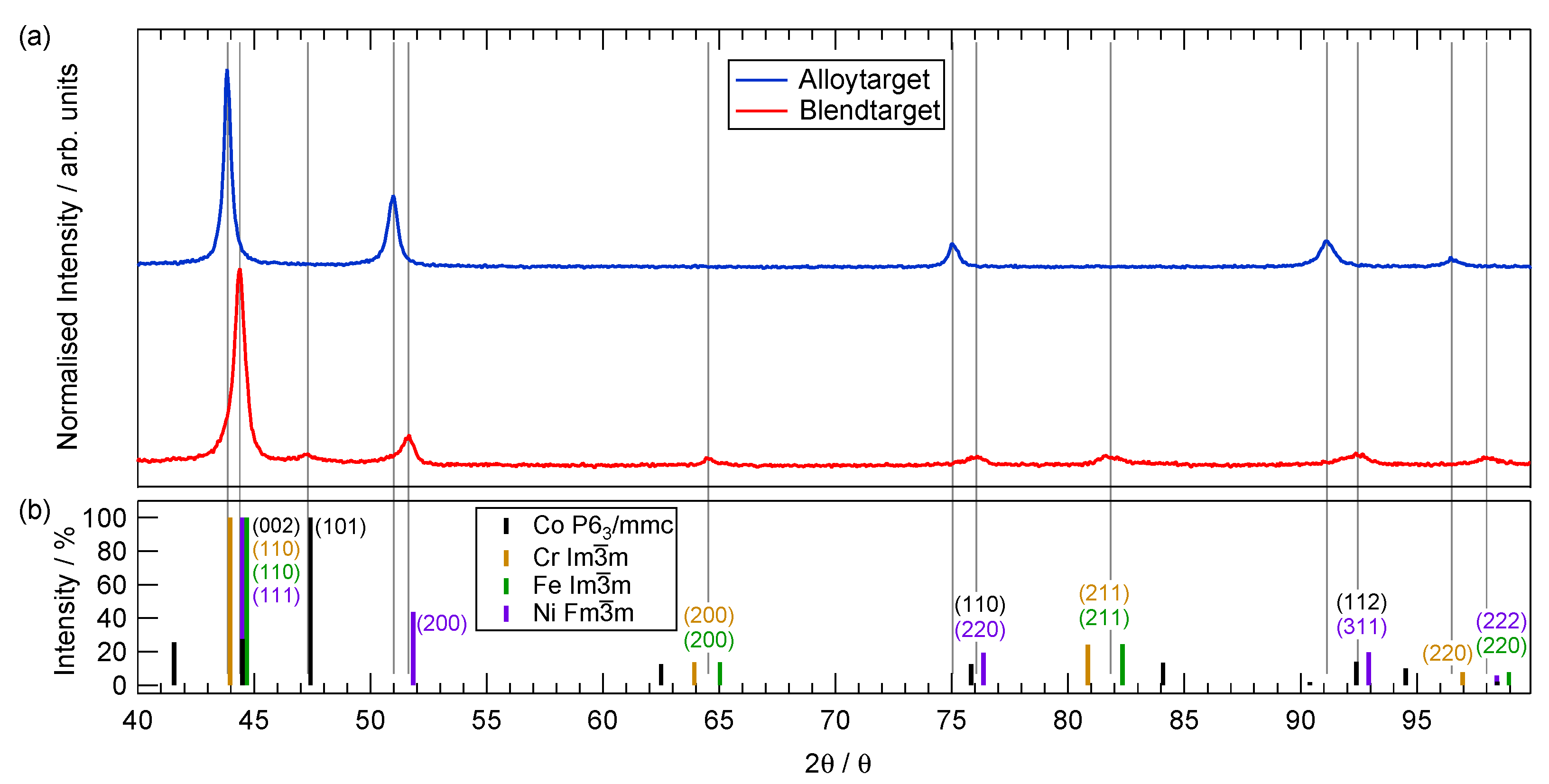
The X-ray diffraction patterns obtained for both sputtering targets used in this work are shown in Figure 3a. To compare the obtained data with the structure of the pure elements used for target fabrication, the peak positions and expected intensity ratio for the fcc structure of Ni, bcc structure of Cr and Fe as well as the hcp structure of Co taken from Crystallography Open Database (COD) are shown in Figure 3b. Lattice plane indices are added for signals where a peak in at least one diffraction pattern was observed. It can be seen that the Alloytarget shows five peaks with decreasing intensity for higher scattering angles. The intensities measured follow a trend very similar to the expectation for the Ni F m 3 ¯ m structure (purple bars), indicating that the Alloytarget has formed a single-phase fcc structure. The lattice constant for CoCrFeNi alloyed in this case has been determined from the diffraction pattern to be 3.575   Å . Similar data have already been reported for CoCrFeNi HEA specimen [21,22,23] and lattice constants for this structure were measured to be in a range of 3.564   Å [24] to 3.58   Å [21]. The Blendtarget shows the characteristic peaks for the Ni fcc structure as well but does not follow the same trend for the intensities. Further, the (101) signal of the Co hcp structure as well as several peaks for the Fe and/or Cr bcc type are clearly visible.
The observation of peaks for the individual elements indicates a separation of the constituents in the Blendtarget, most likely due to the fabrication from a powder mixture leaving the original structure of the pure materials partly unchanged.
To get an insight into the homogeneity of elemental distribution in the sputtering targets, back-scattering electron (BSE) and EDX measurements have been conducted and the results are shown in Figure 4. The Alloytarget clearly shows a uniform distribution of the four main elements involved across an area of several hundreds of μm as illustrated in Figure 4a. The corresponding BSE image does not show areas of different contrast, which again indicates a single phase structure for the Alloytarget. On the contrary, it can be seen that the Blendtarget exhibits clear differences in elemental contribution and BSE contrast (see Figure 4b). The EDX mapping shows localised signals for all four elements, and the shape of the respective structures can be found in the corresponding BSE image as well. The size of the areas with equal intensity is in the range of several 10   μ m for all elements involved, which fits well to the size of the powders used for sintering the Blendtarget. This is a strong hint that the elements in case of this target indeed form a mixture of individual crystals as indicated by the XRD and XRF measurements.
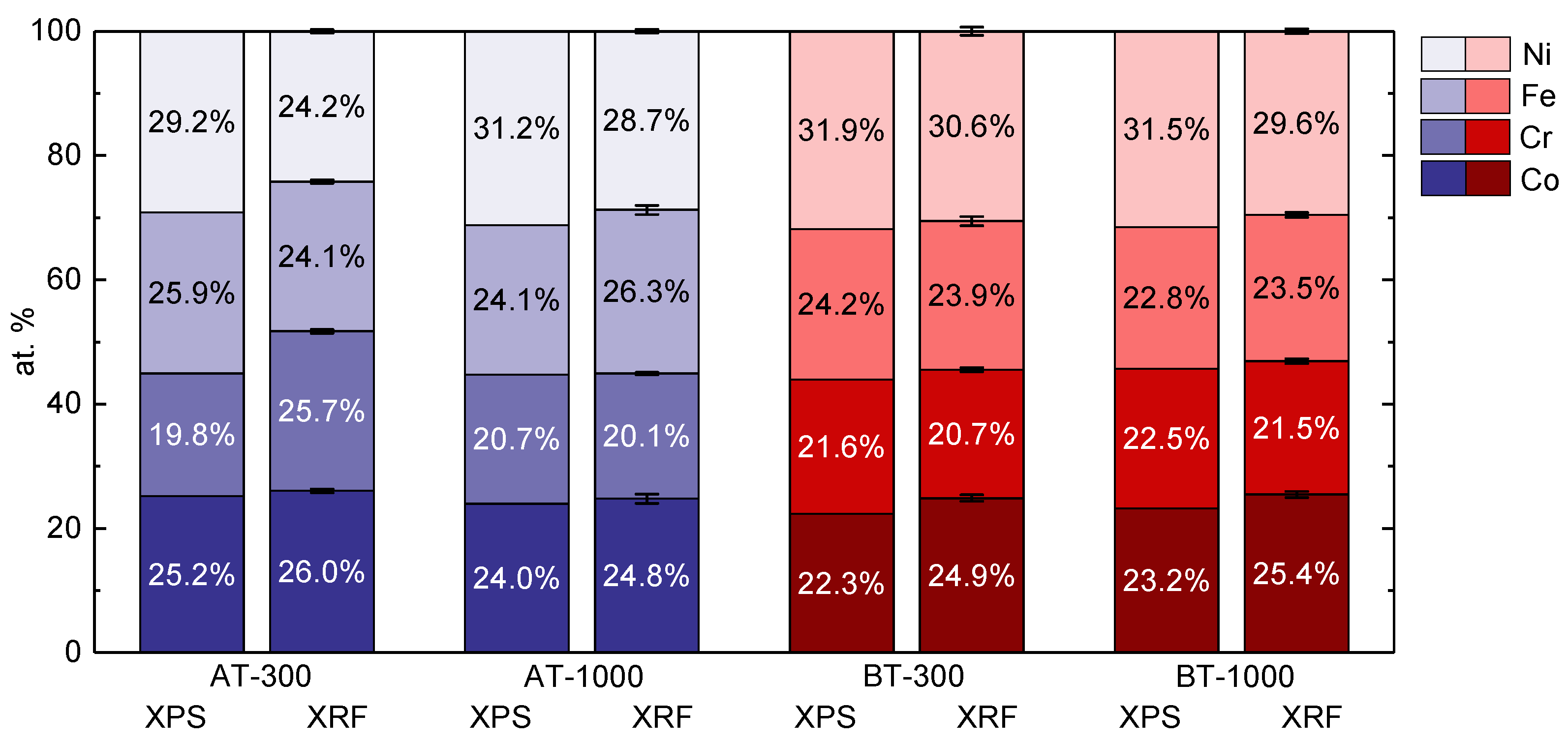
We now discuss the properties of the thin films prepared by sputtering using the two different targets. The compositions of four HEA films were determined in the same way as described for the sputtering targets, and the results are presented in Figure 5. For the XPS measurements, the films on EN 1.4404 stainless-steel substrate were investigated, whereas for XRF, the samples with Si(100) substrates were measured. Overall, the two methods used show a good agreement regarding the atomic concentration of the elements, as was the case for the sputter targets. With the exception of the Ni and Cr content of AT-300, the differences between XPS and XRF results is not more than 3.6 % for all elements. As a general trend, the Ni content is in the range of 30 % for all measurements, which is slightly higher than desired. With a similar difference from the desired value of 25 % , the concentration of Cr is lowered to approximately 20 % . These trends were also observed for both sputter targets as discussed above. This indicates that the composition of the thin films grown by magnetron sputtering under the conditions used in this study is determined by the stoichiometry of the sputter targets and not by the sputtering process. This means that differences in the composition of the films cannot be explained with different sputter rates of the elements, which is the highest for Cr, almost equal for Ni and Fe and the least for Co [25]. If there were a significant influence of the sputter rates on the composition of the films, the Cr content would be expected to be the highest and the Ni to Fe ratio should be almost 1.
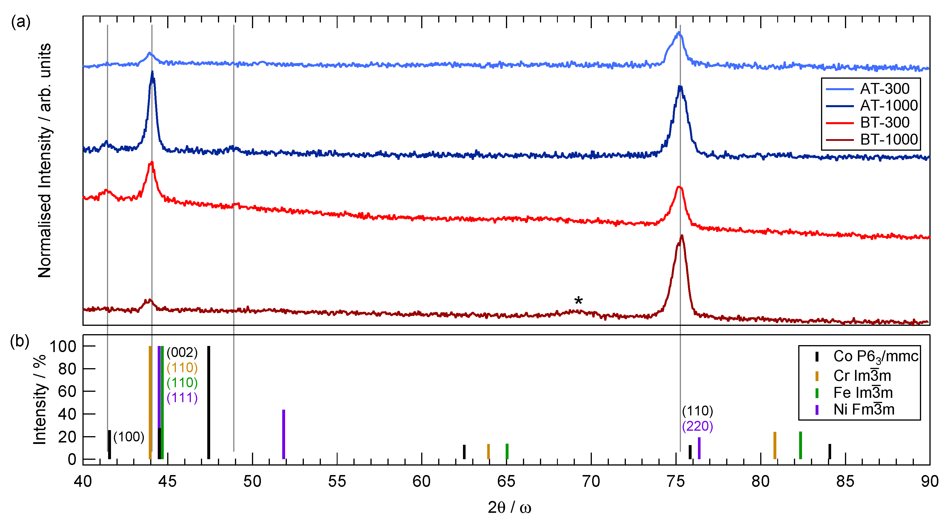
X-ray diffraction patterns obtained from the thin films are shown in Figure 6a. The diffraction pattern labelled AT-300 shows data taken from the film grown on the EN 1.4404 stainless-steel substrate after scaling and subtraction of the substrate diffraction pattern taken in advance. The curves AT-1000, BT-1000 and BT-300 represent data from the thin films deposited on Si(100) substrates. To eliminate the influence of the very intense Si(400) reflection at 69.1 , an offset angle for θ was chosen and the measurements were performed in 2 θ / ω geometry with ω = θ + 2.5 . It is noted that a weak Si(400) signal, marked by an asterisk, is still visible for BT-1000. Two peaks can be found in each of the diffraction patterns at 43.9 and 75.2 with varying intensity ratio. In comparison with the expectations of the underlying pure element data shown in Figure 6b, those signals are identified as the (111) and (220) planes of an fcc lattice similar to the shown Ni signal. The diffraction angles under which the signals show up is very close to those of the Alloytarget where a single-phase fcc structure was identified, and similar values were reported for magnetron sputtered CoCrFeNi on silicon [26]. However, it can be seen that only the (111) and (220) orientation of this phase was measured in the sputtered HEA thin films, which indicates two preferential growth directions with respect to the surface plane. Samples AT-1000 and BT-300 do show a small signal at 2 θ = 41.3 , which can be attributed to the hcp (100) plane of cobalt. Although signals of the Co hcp phase were observed in the XRD data of the Blendtarget as well, the Co(100) peak is not one of them. An additional weak signal can be found around 48.8 in sample AT-1000 that cannot be explained with similarities to the pure element structures. A wider angular range was measured but did not show further peaks.
The surface structure of the sputter deposited CoCrFeNi thin films on Si(001) substrate is shown in Figure 7 for the samples with preparation conditions as mentioned in Table 1. All samples show a fine-grained structure with deviations of individual grain sizes. For samples AT-300 and AT-1000, the grains were measured to have an average dimension of ( 148 ± 25 )   nm and ( 210 ± 24   ) nm , respectively. The thin films BT-300 and BT-1000 deposited from the Blendtarget exhibit structures with mean size in the range of ( 86 ± 12 )   nm and ( 237 ± 28 )   nm . Accordingly, for both targets, the thin films deposited with sputtering power of 300   W (AT-300 and BT-300) show a significantly lower grain size compared to the samples prepared with 1000   W . We find that, independently of the target and power used, the average grain size scales with the deposited thickness of the layers up to a certain critical thickness of about 2–3 micrometer, before the grain size saturates and does not change any more significantly with further increasing film thickness. In the SEM images taken, no indication of separated phases was observed in the form of a strong contrast.

4. Conclusions

In conclusion, it can be said that the thin films prepared by magnetron sputtering from the two sputter targets presented in this work are very similar regarding their investigated properties. No significant differences were found in either elemental composition, phase constitution, or surface structure with the techniques used here. The stoichiometry of all shown samples is in a range of 20–30% for each element as confirmed by XPS and XRF, which resembles the original composition of the used sputtering targets. From XRD measurements, we can conclude that all the films show a primary fcc structure of space group F m 3 ¯ m , although the Blendtarget did show weak XRD signals of the different space groups for the four elements used. The surface has been investigated using SEM, and a homogeneous grainy structure for all HEA thin films could be confirmed, with a reasonable relation between film thickness and grain size. This leads to the final conclusion that both ways of fabrication are suitable to produce sputter targets from which HEA coatings with similar microstructure and homogeneity can be deposited. From an economic point of view, the target fabrication via powder mixture is favourable, because it allows a fast preparation of the materials and leaves out the alloying step, which is time consuming and expensive. Based on these findings, it is obvious that more complex alloy systems must be tested for a similar behaviour.

Author Contributions

Conceptualisation, H.S., T.U., T.L. (Thomas Lindner) and T.S.; methodology, H.S., T.L. (Thomas Lindner); formal analysis, H.S. and N.R.; investigation, H.S., N.R., F.G. and T.L. (Thomas Lindner); resources T.S., T.L. (Thomas Lampke), O.H. and G.W.; writing—original draft preparation, H.S.; writing—review and editing, H.S., F.G., T.U., T.L. (Thomas Lindner) and T.S.; visualisation, H.S.; supervision, T.L. (Thomas Lindner), T.L. (Thomas Lampke), O.H., G.W. and T.S.; project administration, T.L. (Thomas Lindner); funding acquisition, T.L. (Thomas Lindner), T.L. (Thomas Lampke), G.W., T.S. All authors have read and agreed to the published version of the manuscript.

Funding

This study was funded via Sächsische Aufbaubank - Förderbank/SAB-100382175 by the European Social Fund ESF and the Free State of Saxony. The publication of this article was funded by Chemnitz University of Technology.

Informed Consent Statement

Not applicable.

Data Availability Statement

Data available on request.

Acknowledgments

H.S. acknowledges the introduction to the SEM system by Susanne Wolff and Doreen Dentel. The instruction to the magnetron sputter system by Siegfried Peter as well as fruitful discussions are hereby thankfully dignified.

Conflicts of Interest

The authors declare no conflict of interest.

References

  1. Cantor, B.; Chang, I.; Knight, P.; Vincent, A. Microstructural development in equiatomic multicomponent alloys. Mater. Sci. Eng. A 2004, 375–377, 213–218. [Google Scholar] [CrossRef]
  2. Miracle, D.; Senkov, O. A critical review of high entropy alloys and related concepts. Acta Mater. 2017, 122, 448–511. [Google Scholar] [CrossRef] [Green Version]
  3. Miracle, D.B. High-Entropy Alloys: A Current Evaluation of Founding Ideas and Core Effects and Exploring “Nonlinear Alloys”. JOM 2017, 69, 2130–2136. [Google Scholar] [CrossRef] [Green Version]
  4. Wu, J.M.; Lin, S.J.; Yeh, J.W.; Chen, S.K.; Huang, Y.S.; Chen, H.C. Adhesive wear behavior of AlxCoCrCuFeNi high-entropy alloys as a function of aluminum content. Wear 2006, 261, 513–519. [Google Scholar] [CrossRef] [Green Version]
  5. Fazakas, E.; Varga, B.; Geantă, V.; Berecz, T.; Jenei, P.; Voiculescu, I.; Coșniță, M.; Ștefănoiu, R. Microstructure, Thermal, and Corrosion Behavior of the AlAgCuNiSnTi Equiatomic Multicomponent Alloy. Materials 2019, 12, 926. [Google Scholar] [CrossRef] [PubMed] [Green Version]
  6. Li, C.; Li, J.; Zhao, M.; Jiang, Q. Effect of alloying elements on microstructure and properties of multiprincipal elements high-entropy alloys. J. Alloy. Compd. 2009, 475, 752–757. [Google Scholar] [CrossRef]
  7. Kao, Y.F.; Chen, T.J.; Chen, S.K.; Yeh, J.W. Microstructure and mechanical property of as-cast, -homogenized, and -deformed AlxCoCrFeNi (0 ≤ x ≤ 2) high-entropy alloys. J. Alloy. Compd. 2009, 488, 57–64. [Google Scholar] [CrossRef]
  8. Dolique, V.; Thomann, A.L.; Brault, P. High-Entropy Alloys Deposited by Magnetron Sputtering. IEEE Trans. Plasma Sci. 2011, 39, 2478–2479. [Google Scholar] [CrossRef] [Green Version]
  9. Dolique, V.; Thomann, A.L.; Brault, P.; Tessier, Y.; Gillon, P. Complex structure/composition relationship in thin films of AlCoCrCuFeNi high entropy alloy. Mater. Chem. Phys. 2009, 117, 142–147. [Google Scholar] [CrossRef] [Green Version]
  10. Braeckman, B.; Boydens, F.; Hidalgo, H.; Dutheil, P.; Jullien, M.; Thomann, A.L.; Depla, D. High entropy alloy thin films deposited by magnetron sputtering of powder targets. Thin Solid Films 2015, 580, 71–76. [Google Scholar] [CrossRef]
  11. Kim, Y.S.; Park, H.J.; Mun, S.C.; Jumaev, E.; Hong, S.H.; Song, G.; Kim, J.T.; Park, Y.K.; Kim, K.S.; Jeong, S.I.; et al. Investigation of structure and mechanical properties of TiZrHfNiCuCo high entropy alloy thin films synthesized by magnetron sputtering. J. Alloy. Compd. 2019, 797, 834–841. [Google Scholar] [CrossRef]
  12. Kim, H.; Nam, S.; Roh, A.; Son, M.; Ham, M.H.; Kim, J.H.; Choi, H. Mechanical and electrical properties of NbMoTaW refractory high-entropy alloy thin films. Int. J. Refract. Met. Hard Mater. 2019, 80, 286–291. [Google Scholar] [CrossRef]
  13. Alvi, S.; Jarzabek, D.M.; Kohan, M.G.; Hedman, D.; Jenczyk, P.; Natile, M.M.; Vomiero, A.; Akhtar, F. Synthesis and Mechanical Characterization of a CuMoTaWV High-Entropy Film by Magnetron Sputtering. ACS Appl. Mater. Interfaces 2020, 12, 21070–21079. [Google Scholar] [CrossRef] [PubMed]
  14. Liang, J.T.; Cheng, K.C.; Chen, Y.C.; Chiu, S.M.; Chiu, C.; Lee, J.W.; Chen, S.H. Comparisons of plasma-sprayed and sputtering Al0.5CoCrFeNi2 high-entropy alloy coatings. Surf. Coat. Technol. 2020, 403, 126411. [Google Scholar] [CrossRef]
  15. Medina, L.Z.; Riekehr, L.; Jansson, U. Phase formation in magnetron sputtered CrMnFeCoNi high entropy alloy. Surf. Coat. Technol. 2020, 403, 126323. [Google Scholar] [CrossRef]
  16. Horcas, I.; Fernández, R.; Gómez-Rodríguez, J.M.; Colchero, J.; Gómez-Herrero, J.; Baro, A.M. WSXM: A software for scanning probe microscopy and a tool for nanotechnology. Rev. Sci. Instrum. 2007, 78, 013705. [Google Scholar] [CrossRef] [PubMed]
  17. Biesinger, M.C.; Brown, C.; Mycroft, J.R.; Davidson, R.D.; McIntyre, N.S. X-ray photoelectron spectroscopy studies of chromium compounds. Surf. Interface Anal. 2004, 36, 1550–1563. [Google Scholar] [CrossRef]
  18. Biesinger, M.C.; Payne, B.P.; Lau, L.W.M.; Gerson, A.; Smart, R.S.C. X-ray photoelectron spectroscopic chemical state quantification of mixed nickel metal, oxide and hydroxide systems. Surf. Interface Anal. 2009, 41, 324–332. [Google Scholar] [CrossRef]
  19. Biesinger, M.C.; Payne, B.P.; Grosvenor, A.P.; Lau, L.W.; Gerson, A.R.; Smart, R.S. Resolving surface chemical states in XPS analysis of first row transition metals, oxides and hydroxides: Cr, Mn, Fe, Co and Ni. Appl. Surf. Sci. 2011, 257, 2717–2730. [Google Scholar] [CrossRef]
  20. Scofield, J. Hartree-Slater subshell photoionization cross-sections at 1254 and 1487 eV. J. Electron Spectrosc. Relat. Phenom. 1976, 8, 129–137. [Google Scholar] [CrossRef]
  21. Zaddach, A.J.; Niu, C.; Koch, C.C.; Irving, D.L. Mechanical Properties and Stacking Fault Energies of NiFeCrCoMn High-Entropy Alloy. JOM 2013, 65, 1780–1789. [Google Scholar] [CrossRef]
  22. He, F.; Wang, Z.; Wu, Q.; Li, J.; Wang, J.; Liu, C. Phase separation of metastable CoCrFeNi high entropy alloy at intermediate temperatures. Scr. Mater. 2017, 126, 15–19. [Google Scholar] [CrossRef] [Green Version]
  23. Zhang, A.; Han, J.; Su, B.; Meng, J. A novel CoCrFeNi high entropy alloy matrix self-lubricating composite. J. Alloy. Compd. 2017, 725, 700–710. [Google Scholar] [CrossRef]
  24. Lucas, M.S.; Mauger, L.; Muñoz, J.A.; Xiao, Y.; Sheets, A.O.; Semiatin, S.L.; Horwath, J.; Turgut, Z. Magnetic and vibrational properties of high-entropy alloys. J. Appl. Phys. 2011, 109, 07E307. [Google Scholar] [CrossRef] [Green Version]
  25. Matsunami, N.; Yamamura, Y.; Itikawa, Y.; Itoh, N.; Kazumata, Y.; Miyagawa, S.; Morita, K.; Shimizu, R.; Tawara, H. Energy dependence of the ion-induced sputtering yields of monatomic solids. At. Data Nucl. Data Tables 1984, 31, 1–80. [Google Scholar] [CrossRef]
  26. Shi, Y.; Yang, B.; Rack, P.D.; Guo, S.; Liaw, P.K.; Zhao, Y. High-throughput synthesis and corrosion behavior of sputter-deposited nanocrystalline Al (CoCrFeNi)100- combinatorial high-entropy alloys. Mater. Des. 2020, 195, 109018. [Google Scholar] [CrossRef]
Figure 1. X-ray photoelectron spectroscopy survey spectra obtained for the two sputter targets before and after Ar + bombardment. The inset shows a zoom-in of the binding energy range up to 120   eV , which is densely populated by the 3s and 3p core level signals of the involved metals.
Coatings 11 00468 g001
Figure 2. Stoichiometric composition of the Alloytarget and Blendtarget derived from X-ray photoelectron spectroscopy (XPS) and X-ray fluorescence (XRF). The error bars for the latter represent the standard deviation of different measurement positions.
Coatings 11 00468 g002
Figure 3. X-ray diffraction data for the Alloytarget (blue) and the Blendtarget (red) (a) and expected signals for powder diffraction of pure Co, Cr, Fe and Ni (b). The height of the bars represents the expected intensity relative to the most intense signal. Diffraction planes with a corresponding signal in one of the diffraction pattern (vertical lines) are labelled accordingly.
Coatings 11 00468 g003
Figure 4. Backscatter electron images and energy-dispersive X-ray spectroscopy elemental maps of (a) the Alloytarget and (b) the Blendtarget.
Coatings 11 00468 g004
Figure 5. Composition of the deposited thin films as determined by X-ray photoelectron spectroscopy (XPS) and X-ray fluorescence (XRF). The error bars for XRF data represent the standard deviation obtained from several measurements across the samples.
Coatings 11 00468 g005
Figure 6. (a) X-ray diffraction pattern for the sputtered films deposited from the Alloytarget (blue colour code) and from the Blendtarget (red colour code). The expected XRD signals for pure elements are shown in (b). The metallic phases identified in the measurements are marked in the graph. The asterisk marks the residual Si substrate signal.
Coatings 11 00468 g006
Figure 7. Scanning electron microscopy images of (a,b) the samples AT-300 and AT-1000 deposited from the Alloytarget and (c,d) samples BT-300 and BT-1000 sputtered using the Blendtarget.
Coatings 11 00468 g007
Table 1. Deposition parameters for the discussed samples (the time values refer to the actual deposition time excluding presputtering).
SampleTargetPower (W)Time (min)Film Thickness (nm)
AT-300Alloytarget300601210
AT-1000Alloytarget1000601922
BT-300Blendtarget30060737
BT-1000Blendtarget1000603571
Publisher’s Note: MDPI stays neutral with regard to jurisdictional claims in published maps and institutional affiliations.

