
TiO2 Microparticles Incorporation in Coatings Produced by Plasma Electrolytic Oxidation (PEO) on Titanium


Abstract
:1. Introduction
2. Materials and Methods
2.1. PEO Treatment
2.2. Coating Characterization
3. Results
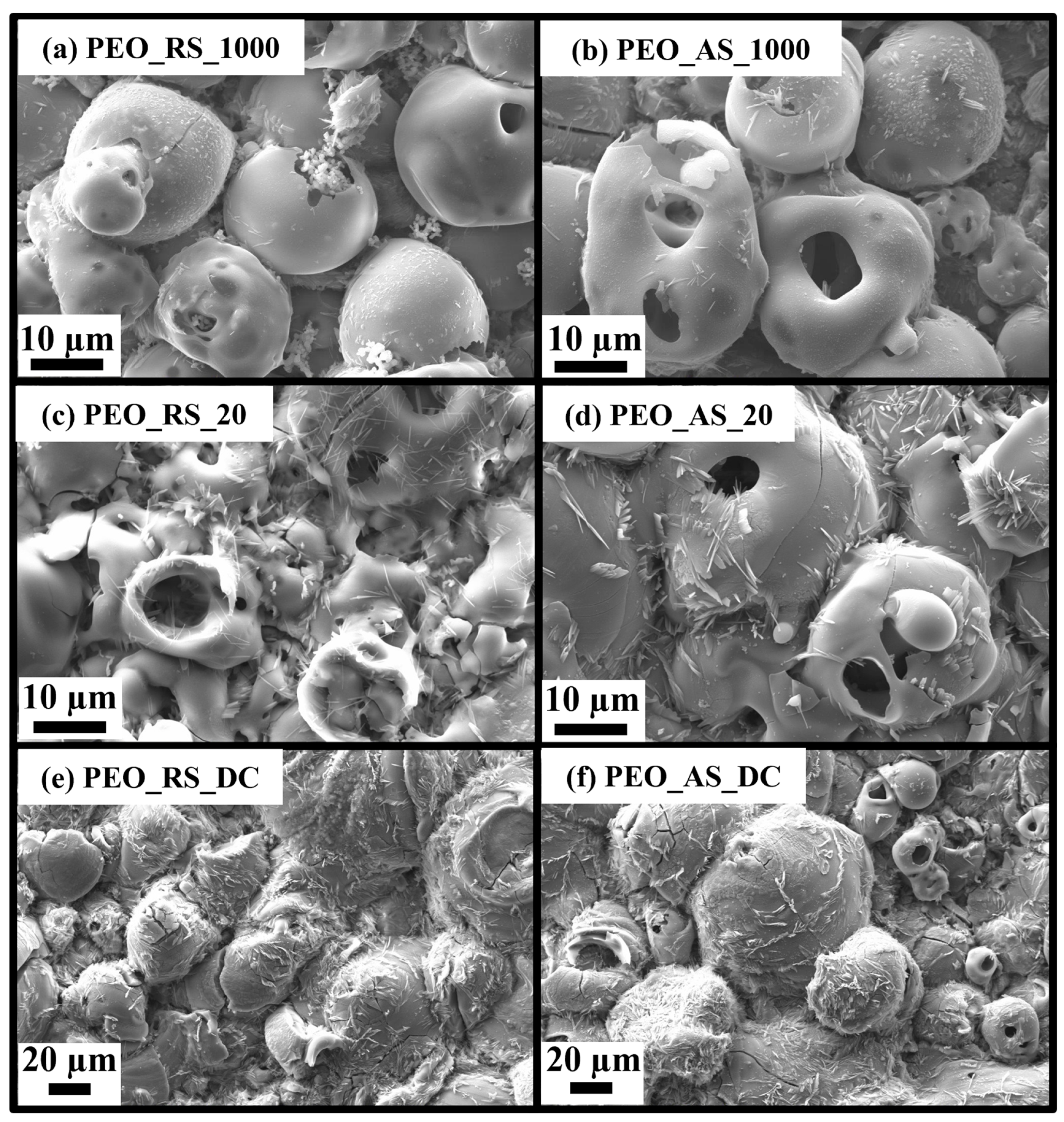
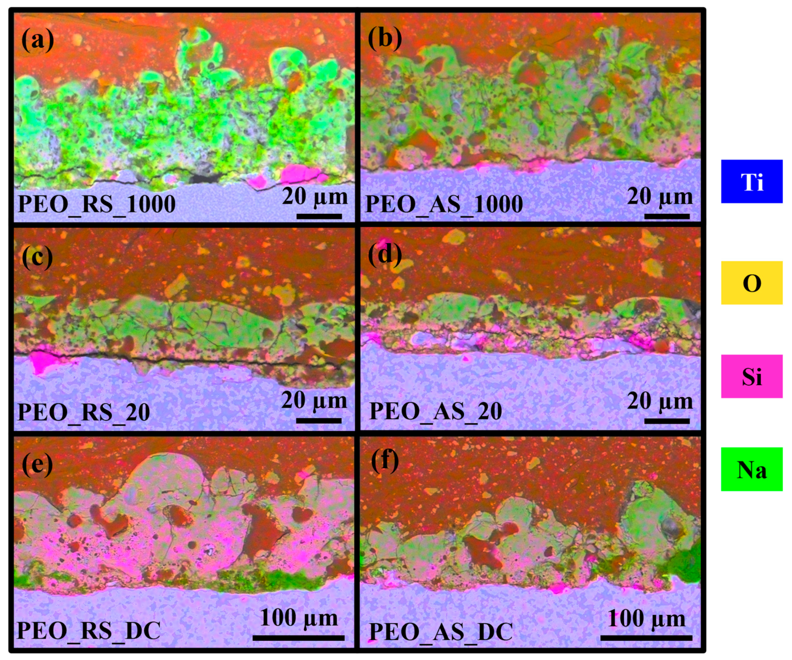
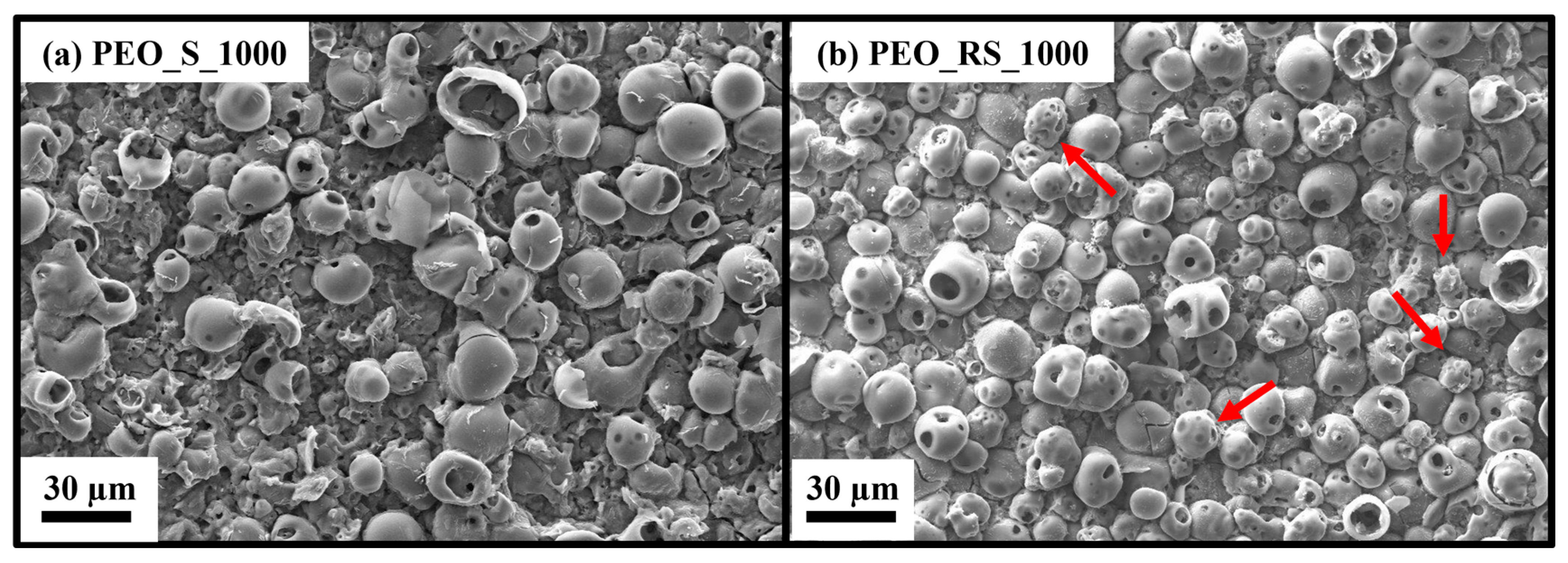
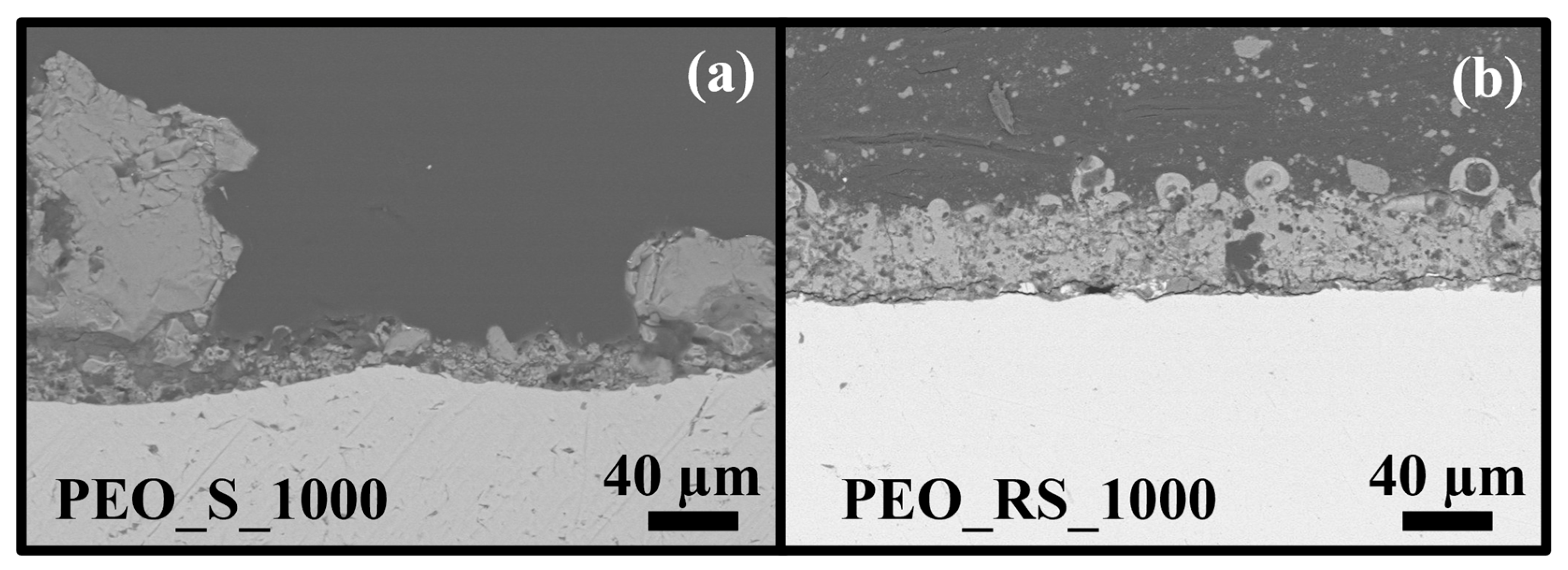
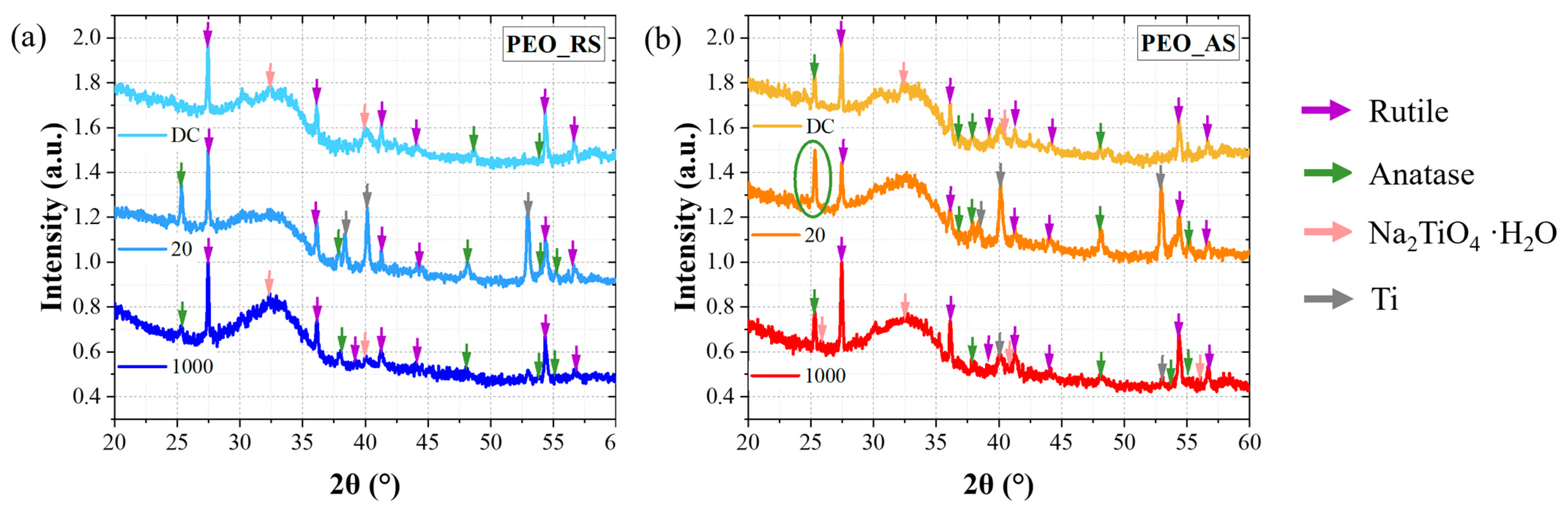
3.1. Morphology, Structure, and Chemical Composition
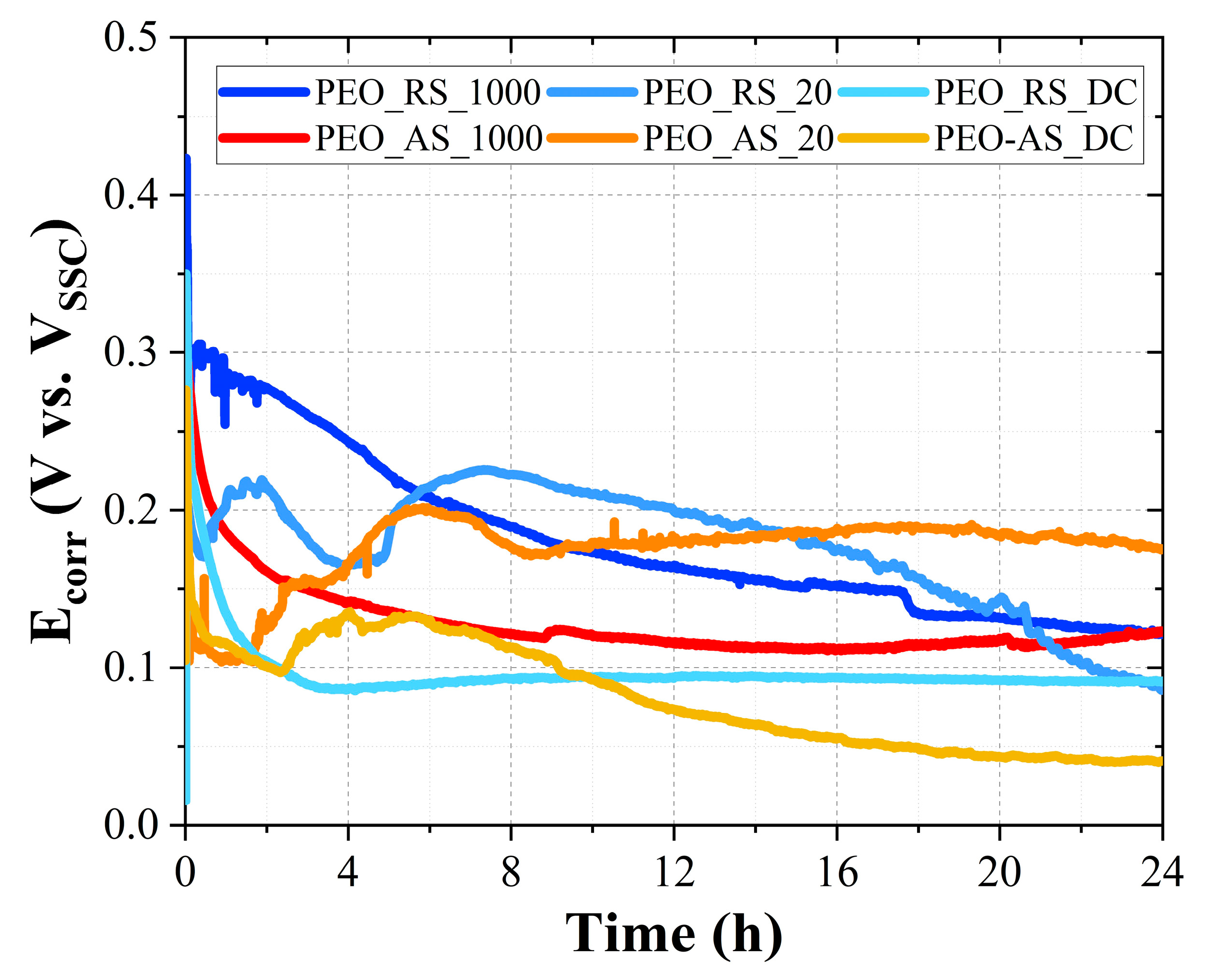
3.2. Free Corrosion Potential
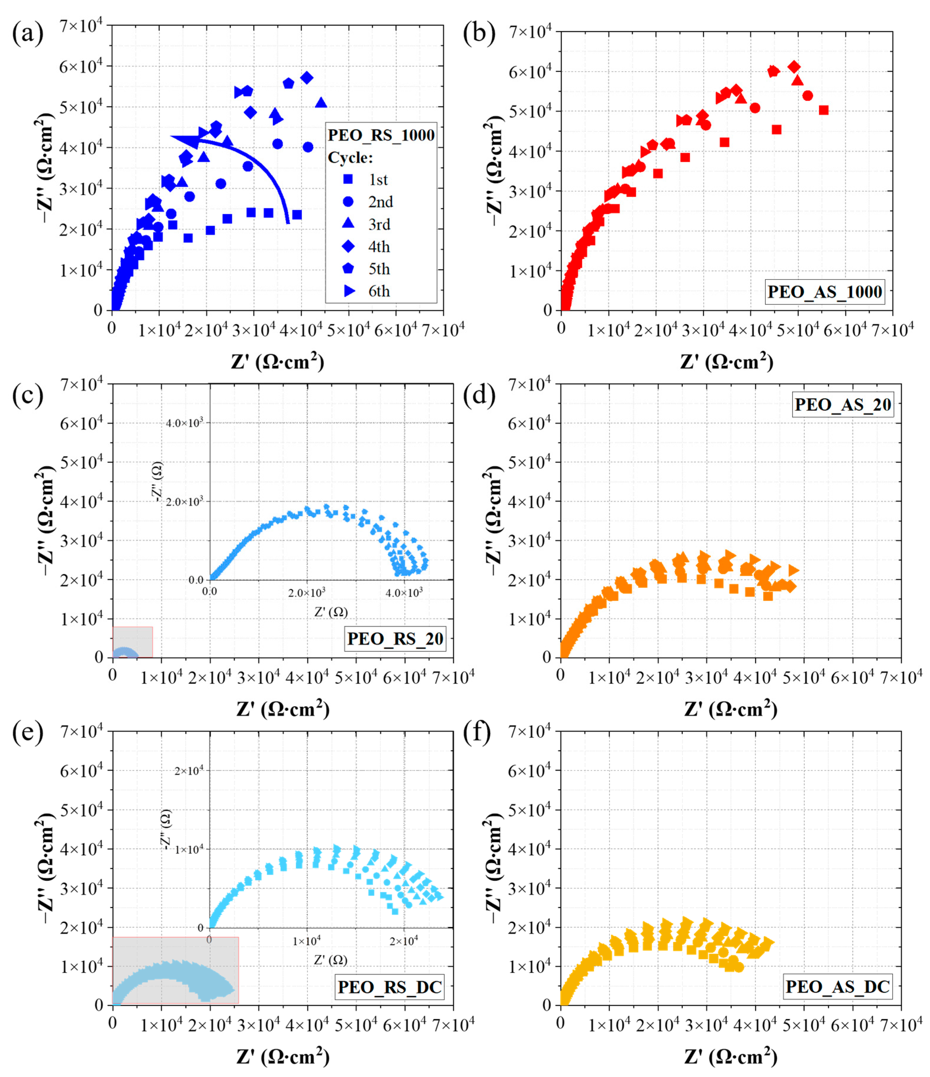
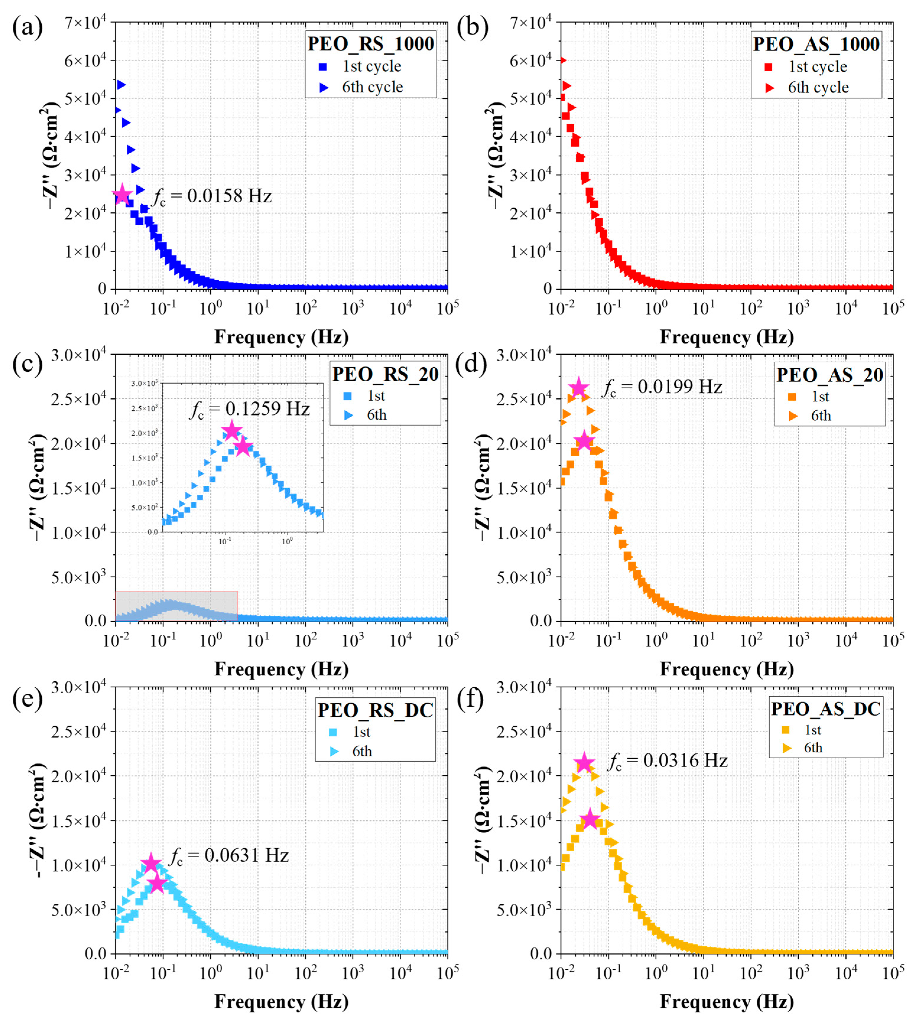
3.3. Electrochemical Impedance Spectroscopy
4. Discussion
4.1. Morphology, Structure, and Chemical Composition
4.2. Free Corrosion Potential
4.3. Electrochemical Impedance Spectroscopy
5. Conclusions
Supplementary Materials
Author Contributions
Funding
Institutional Review Board Statement
Informed Consent Statement
Data Availability Statement
Conflicts of Interest
References
- Sikdar, S.; Menezes, P.V.; Maccione, R.; Jacob, T.; Menezes, P.L. Plasma Electrolytic Oxidation (Peo) Process—Processing, Properties, and Applications. Nanomaterials 2021, 11, 1375. [Google Scholar] [CrossRef]
- Pesode, P.; Barve, S. Surface Modification of Titanium and Titanium Alloy by Plasma Electrolytic Oxidation Process for Biomedical Applications: A Review. Mater. Today Proc. 2021, 46, 594–602. [Google Scholar] [CrossRef]
- Casanova, L.; Gruarin, M.; Pedeferri, M.P.; Ormellese, M. A Comparison between Corrosion Performances of Titanium Grade 2 and 7 in Strong Reducing Acids. Mater. Corros. 2021, 72, 1506–1517. [Google Scholar] [CrossRef]
- Casanova, L.; Ceriani, F.; Pedeferri, M.; Ormellese, M. Addition of Organic Acids during PEO of Titanium in Alkaline Solution. Coatings 2022, 12, 143. [Google Scholar] [CrossRef]
- Lu, X.; Blawert, C.; Zheludkevich, M.L.; Kainer, K.U. Insights into Plasma Electrolytic Oxidation Treatment with Particle Addition. Corros. Sci. 2015, 101, 201–207. [Google Scholar] [CrossRef]
- Lu, X.; Mohedano, M.; Blawert, C.; Matykina, E.; Arrabal, R.; Kainer, K.U.; Zheludkevich, M.L. Plasma Electrolytic Oxidation Coatings with Particle Additions—A Review. Surf. Coat. Technol. 2016, 307, 1165–1182. [Google Scholar] [CrossRef]
- O’Hara, M.; Troughton, S.C.; Francis, R.; Clyne, T.W. The Incorporation of Particles Suspended in the Electrolyte into Plasma Electrolytic Oxidation Coatings on Ti and Al Substrates. Surf. Coat. Technol. 2020, 385, 125354. [Google Scholar] [CrossRef]
- Fattah-alhosseini, A.; Chaharmahali, R.; Babaei, K. Effect of Particles Addition to Solution of Plasma Electrolytic Oxidation (PEO) on the Properties of PEO Coatings Formed on Magnesium and Its Alloys: A Review. J. Magnes. Alloy. 2020, 8, 799–818. [Google Scholar] [CrossRef]
- Aliofkhazraei, M.; Macdonald, D.D.; Matykina, E.; Parfenov, E.V.; Egorkin, V.S.; Curran, J.A.; Troughton, S.C.; Sinebryukhov, S.L.; Gnedenkov, S.V.; Lampke, T.; et al. Review of Plasma Electrolytic Oxidation of Titanium Substrates: Mechanism, Properties, Applications and Limitations. Appl. Surf. Sci. Adv. 2021, 5, 100121. [Google Scholar] [CrossRef]
- Shokouhfar, M.; Allahkaram, S.R. Formation Mechanism and Surface Characterization of Ceramic Composite Coatings on Pure Titanium Prepared by Micro-Arc Oxidation in Electrolytes Containing Nanoparticles. Surf. Coat. Technol. 2016, 291, 396–405. [Google Scholar] [CrossRef]
- Fattah-alhosseini, A.; Molaei, M.; Babaei, K. The Effects of Nano- and Micro-Particles on Properties of Plasma Electrolytic Oxidation (PEO) Coatings Applied on Titanium Substrates: A Review. Surf. Interfaces 2020, 21, 100659. [Google Scholar] [CrossRef]
- Lu, X.; Blawert, C.; Mohedano, M.; Scharnagl, N.; Zheludkevich, M.L.; Kainer, K.U. Influence of Electrical Parameters on Particle Uptake during Plasma Electrolytic Oxidation Processing of AM50 Mg Alloy. Surf. Coat. Technol. 2016, 289, 179–185. [Google Scholar] [CrossRef]
- Casanova, L.; La Padula, M.; Pedeferri, M.P.; Diamanti, M.V.; Ormellese, M. An Insight into the Evolution of Corrosion Resistant Coatings on Titanium during Bipolar Plasma Electrolytic Oxidation in Sulfuric Acid. Electrochim. Acta 2021, 379, 138190. [Google Scholar] [CrossRef]
- Casanova, L.; Arosio, M.; Hashemi, M.T.; Pedeferri, M.; Botton, G.A.; Ormellese, M. Influence of Stoichiometry on the Corrosion Response of Titanium Oxide Coatings Produced by Plasma Electrolytic Oxidation. Corros. Sci. 2022, 203, 110361. [Google Scholar] [CrossRef]
- Aliasghari, S.; Skeleton, P.; Thompson, G.E. Plasma Electrolytic Oxidation of Titanium in a Phosphate/Silicate Electrolyte and Tribological Performance of the Coatings. Appl. Surf. Sci. 2014, 316, 463–476. [Google Scholar] [CrossRef]
- Kamaluddin, H.S.; Basahel, S.N.; Narasimharao, K.; Mokhtar, M. H-ZSM-5 Materials Embedded in an Amorphous Silica Matrix: Highly Selective Catalysts for Propylene in Methanol-to-Olefin Process. Catalysts 2019, 9, 364. [Google Scholar] [CrossRef]
- Wojcieszak, D.; Mazur, M.; Kaczmarek, D.; Poniedziałek, A.; Osekowska, M. An Impact of the Copper Additive on Photocatalytic and Bactericidal Properties of TiO2 Thin Films. Mater. Sci. Pol. 2017, 35, 421–426. [Google Scholar] [CrossRef]
- Lu, X.; Shih, K.; Li, X.Y.; Liu, G.; Zeng, E.Y.; Wang, F. Accuracy and Application of Quantitative X-Ray Diffraction on the Precipitation of Struvite Product. Water Res. 2016, 90, 9–14. [Google Scholar] [CrossRef]
- Kalapathy, U.; Proctor, A.; Shultz, J. Silicate Thermal Insulation Material from Rice Hull Ash. Ind. Eng. Chem. Res. 2003, 42, 46–49. [Google Scholar] [CrossRef]
- Qin, J.; Shi, X.; Li, H.; Zhao, R.; Li, G.; Zhang, S.; Ding, L.; Cui, X.; Zhao, Y.; Zhang, R. Performance and Failure Process of Green Recycling Solutions for Preparing High Degradation Resistance Coating on Biomedical Magnesium Alloys. Green Chem. 2022, 24, 8113–8130. [Google Scholar] [CrossRef]
- Zhang, X.; Aliasghari, S.; Němcová, A.; Burnett, T.L.; Kuběna, I.; Šmíd, M.; Thompson, G.E.; Skeldon, P.; Withers, P.J. X-ray Computed Tomographic Investigation of the Porosity and Morphology of Plasma Electrolytic Oxidation Coatings. ACS Appl. Mater. Interfaces 2016, 8, 8801–8810. [Google Scholar] [CrossRef]
- Dehnavi, V.; Luan, B.L.; Shoesmith, D.W.; Liu, X.Y.; Rohani, S. Effect of Duty Cycle and Applied Current Frequency on Plasma Electrolytic Oxidation (PEO) Coating Growth Behavior. Surf. Coat. Technol. 2013, 226, 100–107. [Google Scholar] [CrossRef]
- Yue, Y.; Exarhos, S.; Nam, J.; Lee, D.; Linic, S.; Bruggeman, P.J. Quantification of Plasma Produced OH and Electron Fluxes at the Liquid Anode and Their Role in Plasma Driven Solution Electrochemistry. Plasma Sources Sci. Technol. 2022, 31, 125008. [Google Scholar] [CrossRef]
- Mortazavi, G.; Jiang, J.; Meletis, E.I. Investigation of the Plasma Electrolytic Oxidation Mechanism of Titanium. Appl. Surf. Sci. 2019, 488, 370–382. [Google Scholar] [CrossRef]
- Rogov, A.B.; Matthews, A.; Yerokhin, A. Role of Cathodic Current in Plasma Electrolytic Oxidation of Al: A Quantitative Approach to in-Situ Evaluation of Cathodically Induced Effects. Electrochim. Acta 2019, 317, 221–231. [Google Scholar] [CrossRef]
- Quintero, D.; Galvis, O.; Calderón, J.A.; Castaño, J.G.; Echeverría, F. Effect of Electrochemical Parameters on the Formation of Anodic Films on Commercially Pure Titanium by Plasma Electrolytic Oxidation. Surf. Coat. Technol. 2014, 258, 1223–1231. [Google Scholar] [CrossRef]
- Hyoung, G.L.; Zuo, J.M. Growth and Phase Transformation of Nanometer-Sized Titanium Oxide Powders Produced by the Precipitation Method. J. Am. Ceram. Soc. 2004, 87, 473–479. [Google Scholar] [CrossRef]
- Li, M.J.; Chi, Z.Y.; Wu, Y.C. Morphology, Chemical Composition and Phase Transformation of Hydrothermal Derived Sodium Titanate. J. Am. Ceram. Soc. 2012, 95, 3297–3304. [Google Scholar] [CrossRef]
- Durdu, S.; Usta, M. The Tribological Properties of Bioceramic Coatings Produced on Ti6Al4V Alloy by Plasma Electrolytic Oxidation. Ceram. Int. 2014, 40, 3627–3635. [Google Scholar] [CrossRef]
- Hanaor, D.A.H.; Sorrell, C.C. Review of the Anatase to Rutile Phase Transformation. J. Mater. Sci. 2011, 46, 855–874. [Google Scholar] [CrossRef]
- Lasheen, T.A. Hydrometallurgy Soda Ash Roasting of Titania Slag Product from Rosetta Ilmenite. Hydrometallurgy 2008, 93, 124–128. [Google Scholar] [CrossRef]
- Dubenko, A.V.; Nikolenko, M.V.; Aksenenko, E.V.; Kostyniuk, A.; Likozar, B. Mechanism, Thermodynamics and Kinetics of Rutile Leaching Process by Sulfuric Acid Reactions. Processes 2020, 8, 640. [Google Scholar] [CrossRef]
- Casanova, L.; Menegazzo, M.; Goto, F.; Pedeferri, M.; Duò, L.; Ormellese, M.; Bussetti, G. Investigating the Activation of Passive Metals by a Combined In-Situ AFM and Raman Spectroscopy System: A Focus on Titanium. Sci. Rep. 2023, 13, 6117. [Google Scholar] [CrossRef]
- Shokouhfar, M.; Dehghanian, C.; Montazeri, M.; Baradaran, A. Preparation of Ceramic Coating on Ti Substrate by Plasma Electrolytic Oxidation in Different Electrolytes and Evaluation of Its Corrosion Resistance: Part II. Appl. Surf. Sci. 2012, 258, 2416–2423. [Google Scholar] [CrossRef]


| Label | Base Solution | Additives | Frequency (Hz) |
|---|---|---|---|
| PEO_RS_1000 | 5 gL−1 RP + 4 gL−1 Na2SiO3 | 1000 | |
| PEO_AS_1000 | 5 gL−1 AP + 4 gL−1 Na2SiO3 | 1000 | |
| PEO_RS_20 | 5 gL−1 RP + 4 gL−1 Na2SiO3 | 20 | |
| PEO_AS_20 | 1 M NaOH | 5 gL−1 AP + 4 gL−1 Na2SiO3 | 20 |
| PEO_RS_DC | 5 gL−1 RP + 4 gL−1 Na2SiO3 | - | |
| PEO_AS_DC | 5 gL−1 AP + 4 gL−1 Na2SiO3 | - | |
| PEO_S_1000 | 4 gL−1 Na2SiO3 | 1000 |
| Sample | Porosity % | Average Pore Diameter (μm) |
|---|---|---|
| PEO_RS_1000 | 28 | 3.1 2.2 |
| PEO_AS_1000 | 31 | 7.2 3.7 |
| PEO_RS_20 | 41 | 5.6 2.6 |
| PEO_AS_20 | 43 | 6.4 2.7 |
| PEO_RS_DC | 26 | 23.5 8.2 |
| PEO_AS_DC | 35 | 18.9 9.3 |
| Sample | Rp 1st Cycle (Ω·cm−2·105) | Rp 6th Cycle (Ω·cm−2·105) |
|---|---|---|
| PEO_RS_1000 | 0.58 | 1.32 |
| PEO_AS_1000 | 1.05 | 1.47 |
| PEO_RS_20 | 0.04 | 0.05 |
| PEO_AS_20 | 0.49 | 0.64 |
| PEO_RS_DC | 0.20 | 0.25 |
| PEO_AS_DC | 0.40 | 0.52 |
| Sample | fc 1st Cycle (Hz) | fc 6th Cycle (Hz) |
|---|---|---|
| PEO_RS_1000 | 0.0158 | <10−2 |
| PEO_AS_1000 | <10−2 | <10−2 |
| PEO_RS_20 | 0.1995 | 0.1259 |
| PEO_AS_20 | 0.0316 | 0.0199 |
| PEO_RS_DC | 0.0794 | 0.0631 |
| PEO_AS_DC | 0.0398 | 0.0316 |
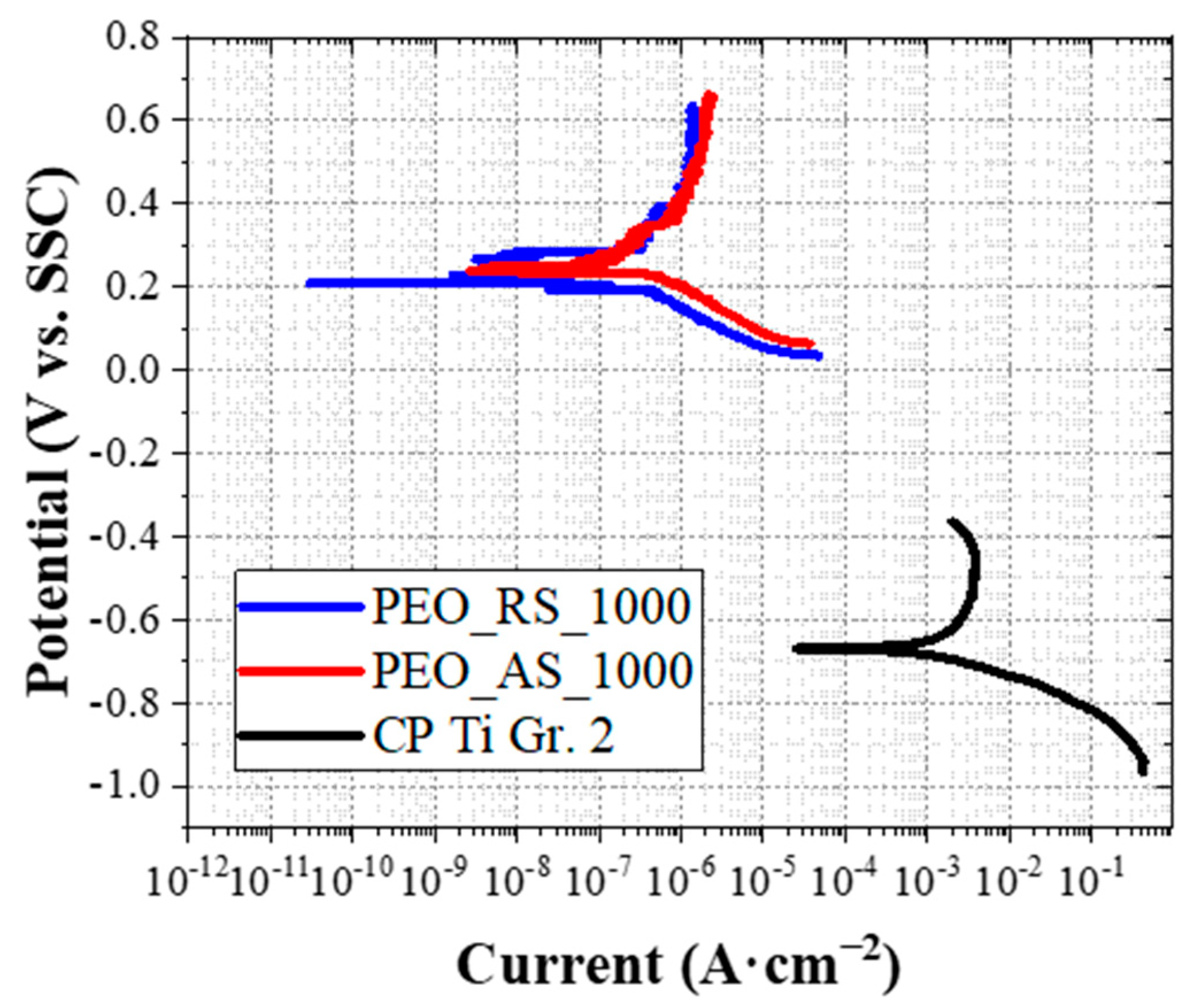
| Sample | Ecorr (mV vs. SSC) | icorr (μA·cm−2) | (mV·dec−1) | (mV·dec−1) |
|---|---|---|---|---|
| CP Ti Gr. 2 | −668 | 5431 | 336 | 754 |
| PEO_RS_1000 | 209 | 0.33 | 541 | 110 |
| PEO_AS_1000 | 238 | 0.59 | 665 | 119 |
Disclaimer/Publisher’s Note: The statements, opinions and data contained in all publications are solely those of the individual author(s) and contributor(s) and not of MDPI and/or the editor(s). MDPI and/or the editor(s) disclaim responsibility for any injury to people or property resulting from any ideas, methods, instructions or products referred to in the content. |
© 2023 by the authors. Licensee MDPI, Basel, Switzerland. This article is an open access article distributed under the terms and conditions of the Creative Commons Attribution (CC BY) license (https://creativecommons.org/licenses/by/4.0/).
Share and Cite
Ceriani, F.; Casanova, L.; Massimini, L.; Brenna, A.; Ormellese, M. TiO2 Microparticles Incorporation in Coatings Produced by Plasma Electrolytic Oxidation (PEO) on Titanium. Coatings 2023, 13, 1718. https://0-doi-org.brum.beds.ac.uk/10.3390/coatings13101718
Ceriani F, Casanova L, Massimini L, Brenna A, Ormellese M. TiO2 Microparticles Incorporation in Coatings Produced by Plasma Electrolytic Oxidation (PEO) on Titanium. Coatings. 2023; 13(10):1718. https://0-doi-org.brum.beds.ac.uk/10.3390/coatings13101718
Chicago/Turabian StyleCeriani, Federica, Luca Casanova, Luca Massimini, Andrea Brenna, and Marco Ormellese. 2023. "TiO2 Microparticles Incorporation in Coatings Produced by Plasma Electrolytic Oxidation (PEO) on Titanium" Coatings 13, no. 10: 1718. https://0-doi-org.brum.beds.ac.uk/10.3390/coatings13101718