
Structural Damage Detection Based on Static and Dynamic Flexibility: A Review and Comparative Study

1
College of Civil Engineering and Architecture, Zhejiang University, Hangzhou 310058, China
2
School of Civil and Transportation Engineering, Ningbo University of Technology, Ningbo 315211, China
3
Ningbo Roaby Technology Industrial Group Co., Ltd., Ningbo 315800, China
4
Key Laboratory of New Technology for Construction of Cities in Mountain Area, Ministry of Education, School of Civil Engineering, Chongqing University, Chongqing 400045, China
5
School of Architectural Engineering, Shaoxing University Yuanpei College, Shaoxing 312000, China
*
Authors to whom correspondence should be addressed.
Coatings 2024, 14(1), 31; https://0-doi-org.brum.beds.ac.uk/10.3390/coatings14010031
Submission received: 28 November 2023
/
Revised: 21 December 2023
/
Accepted: 25 December 2023
/
Published: 26 December 2023
(This article belongs to the Special Issue Development and Characterization of New Construction Materials and Coatings)
Abstract
:Material damage in structures must be detected in a timely manner to prevent engineering accidents. Damage detection based on structural flexibility has attracted widespread attention in recent years due to its simplicity and practicality. This article provides a detailed overview of damage detection methods based on structural flexibility. Depending on the calculation method and data used, flexibility-based methods can be divided into the following categories: flexibility difference, flexibility derivative index, flexibility sensitivity, flexibility decomposition, static flexibility, and combinations of flexibility with other methods. The basic principles and main calculation formulas of various flexibility methods are explained, and their advantages and disadvantages are analyzed. For the method using flexibility difference, the advantage is that the calculation is very simple and does not require the construction of a finite element model of the structure. The disadvantage is that it requires the measurement of modal data of the intact structure, and this method cannot quantitatively assess the degree of damage. For the method using the flexibility derivative index, the advantage is that it only requires the modal data of the damaged structure to locate the damage, but this method is particularly sensitive to noise in the data and is prone to misjudgment. For methods based on flexibility sensitivity and flexibility decomposition, the advantage is that they can simultaneously obtain the location and degree of damage in the structure, but the disadvantage is that they require the establishment of accurate finite element models in advance. Static flexibility methods can compensate for the shortcomings of dynamic flexibility methods, but they usually affect the normal use of the structure during static testing. Combining flexibility-based methods with advanced intelligent algorithms and other methods can further improve their accuracy and efficiency in identifying structural damage. Finally, this article discusses the challenges that have not yet been solved among damage detection methods based on structural flexibility.
1. Introduction
All kinds of engineering structures, such as buildings, bridges, biomimetic structures, spacecraft, and mechanical equipment, will inevitably be damaged during their service life due to environmental corrosion, aging of the material, excessive loads, and other adverse effects. Local damage in the structure may lead to the rapid destruction of the whole structure, thus leading to serious engineering accidents. Therefore, it is an inevitable requirement to evaluate the damage to engineering structures during their use. Because the static and dynamic responses of a structure are functions of the physical structural parameters (such as the elastic modulus and cross-sectional area), structural damage (a reduction in the elastic modulus or cracking) will inevitably lead to changes in the structural response parameters. Therefore, by measuring the static or dynamic response parameters of the structure, it is possible to evaluate whether damage has occurred, the location of damage, and the severity of damage. In recent decades, many structural damage assessment methods using changes in the static or dynamic response have been developed [1,2,3,4,5,6,7,8,9]. Among the existing methods, flexibility-based damage assessment methods have been widely studied because of their outstanding advantages: the structural flexibility matrix can be obtained accurately through dynamic or static testing of the structure; structural flexibility is more sensitive to structural damage than other response parameters, such as vibration frequencies and mode shapes; and sensitivity analyses of structural flexibility are simpler than those of other dynamic parameters. At present, there is no report of a review specifically targeting flexibility-based damage assessment methods. In view of this, a thematic review of flexibility-based damage identification methods published in the last few decades is presented in this work. The existing damage assessment methods based on flexibility are divided into six categories, and the basic principles of each category are expounded in detail. Moreover, this work also provides a concise comparative study of the various flexibility-based methods through several numerical examples to further validate the advantages and disadvantages of these flexibility-based methods. At the same time, the problems existing in the damage assessment methods based on structural flexibility are also pointed out, which will provide a reference for future research.
2. Definition of Structural Flexibility and Testing Methods
It is known that the stiffness matrix and mass matrix of a structure with degrees of freedom (DOFs) can be easily obtained from structural finite element model (FEM). The flexibility matrix of a structure is defined in Equation (1) as the inverse of the stiffness matrix; that is [4],
In engineering practice, structural flexibility can be obtained through two methods: static testing or dynamic testing. The basic principles of the two methods are explained as follows. For static testing, the displacement of a structure under a certain static load can be calculated by Equations (2) or (3) as [10]
When the load vector is taken as a single-point load , Equation (3) becomes
where is the number of DOFs of structural FEM. From Equation (4), the -th column vector in the flexibility matrix is the displacement generated when a unit force is applied at the -th DOF in the structure. In practice, the displacement can be easily measured in a static experiment by the displacement meters. As a result, structural flexibility can be obtained through a series of static single-point loading tests. Figure 1 shows the process of obtaining the flexibility matrix through static testing using a beam structure as an example. In Figure 1, the static concentrated load is sequentially moved to each node, and then the corresponding static displacement data of all nodes are measured. These static displacement data can be combined to obtain the flexibility matrix .
On the other hand, structural flexibility can also be approximately obtained through structural free-vibration tests. Using the system matrices and , the free-vibration modes can be computed through the following generalized eigenvalue problem as [11]:
where is the -th eigenvalue (i.e., angular frequency, ) and is the mass-normalized eigenvector (i.e., mode shape). In practice, the eigenvalue and the eigenvector can be measured by the structural free-vibration experiment. Equations (5) and (6) can be rewritten for vibration modes as [12]:
where is an -dimensional identity matrix. In Equations (7) and (8), is the mode shape matrix and is the angular frequency matrix, as follows:
From Equation (8), one obtains
From Equations (7) and (11), one obtains
Using Equation (13), the flexibility matrix can be expressed as:
From Equations (11), (12) and (14), one has
Using Equations (9) and (10), Equation (15) can be expressed as [13]:
Due to , structural flexibility can be approximated from Equation (16) as [12,13]:
where denotes the number of the measured modes. Equation (17) shows that the structural flexibility can be approximated when the first few vibration modes ( and , ) are measured through a structural dynamic experiment. Figure 2 shows the process of obtaining the flexibility matrix through dynamic testing using a beam structure as an example.
3. Flexibility-Based Damage Assessment
After obtaining the structural flexibility through static or dynamic tests, the potential damage in the structure can be evaluated on the basis of the changes in or the inherent characteristics of the structural flexibility. In recent literature reviews [1,2,3,4,5,6,7,8,9], the damage identification methods have usually been classified according to the type of data used and the algorithm used for processing the data. According to this principle, flexibility-based damage assessment methods can be divided into six types, as shown in Figure 3.
3.1. Localizing Damage Using Differences in the Flexibility
Pandey and Biswas [14,15] first proposed a method for identifying the locations of damage by utilizing changes in the flexibility matrices before and after damage. Meng et al. [16] used the method of the differences in the dynamic flexibility for detecting damage in suspension bridge cables. Xi et al. [17] used the changes in the diagonal elements of the flexibility matrix to identify damage in crane girders. Wang et al. [18] used the difference in the modal flexibility for identifying damage in the pile foundations of a high-piled wharf. Lu et al. [19] made a scale model of a masonry pagoda and conducted dynamic testing to obtain the flexibility matrix, and then they used the differences in the flexibility to identify damage in the tower’s structure. For the undamaged and damaged structures, Equation (17) can be rewritten as
where and denote the undamaged and damaged flexibility matrices, and denote the -th vibration mode of the undamaged structure, and denote the -th vibration mode of the damaged structure, and is the number of the measured modes. From Equations (18) and (19), the flexibility change can be obtained as
After is calculated by Equation (20), the element with the highest absolute value in each column vector of is taken to locate the damage. Pandey and Biswas validated the feasibility of the flexibility change method for damage localization through numerical and experimental analyses of cantilever beams, simply supported beams, and free beams. Toksoy and Aktan [20,21] used the flexibility matrix obtained from the measured modes to evaluate the state of bridge structures. Through numerical and experimental research on a three-span, concrete bridge, Raghavedrachar and Aktan [22] verified that the structural flexibility was more sensitive to local damage than the vibration frequencies and mode shapes. The research conducted by Zhao and Dewolf [23] also reached the same conclusion. Ko [24] studied a multi-stage method for identifying structural damage using the rate of changes in the diagonal elements of the flexibility matrix. The rate of changes in the diagonal elements of the flexibility matrix before and after damage can be calculated through Equation (21), as follows:
Catbas et al. [25] found that modal flexibility can be obtained by measuring the frequency response function of the structure. Random errors and modal truncation can have adverse effects on the results of assessing the damage. Tomaszewska [26] discussed the impact of data noise on the modal flexibility and the curvature of the mode shape. Koo et al. [27] and Sung et al. [28] used the modal flexibility measured through environmental vibration to estimate deflection in the interlayer caused by damage. Hu et al. [29] extracted a damage indicator by calculating the local modal flexibility before and after damage to wood. Altunışık et al. [30] compared the accuracy of localizing the damage between the modal flexibility method and the modal curvature method. They found that the method using the change in the modal flexibility was superior to the modal curvature method for estimating a crack’s location on the basis of a small amount of experimental data. Meng et al. [31] applied the method using the change in the modal flexibility to detect damage to a suspension bridge’s suspension rods. Wickramasinghe et al. [32] developed a vertical damage index and a lateral damage index from the modal flexibility to detect and locate damage in the main cables and hangers of suspension bridges. It was found that the proposed vertical damage index could accurately detect actual damage to the suspension bridge using only the first few modes. For large-scale structures, the use of manual excitation in a structural dynamic test is time-consuming and labor-intensive, and, in some cases, it is completely impossible. Online monitoring of these structures can only obtain the modal data of structural vibrations under environmental excitation. In this case, the structural flexibility matrix cannot be directly obtained because only non-normalized vibration modes can be obtained under environmental excitation. To solve this problem, Doebling et al. [33] studied a method for calculating the structural flexibility matrix using modal data under environmental excitation and discussed four methods of modal normalization. Duan et al. [34,35] used the proportional flexibility matrix to solve problems of detecting damage under environmental excitation.
These methods using changes in the flexibility can be divided into three categories: (1) those using the element with the highest absolute value in each column vector of to locate the damage, (2) those using the absolute values of the diagonal elements to locate the damage, and (3) those using the rate of change in the diagonal elements in to locate the damage. From the published research results, it can be seen that the recognition effect of using the rates of change in diagonal elements of is relatively good. Overall, the advantages of this type of method are that (1) the process of finite element modeling can be avoided because is directly obtained from structural dynamic tests before and after damage, (2) the accuracy of recognition is only affected by the accuracy of the modal testing, and (3) incompletely measured vibration modes can be directly used in calculations without the need for expansion of the mode. The disadvantages of this type of method are that (1) only the location of the damage can be determined by using this method, and the extent of the damage cannot be quantitatively determined, and (2) the results of recognition depend strongly on the number and location of the measurement points. Damage in areas without measurement points is prone to be missed in the diagnosis.
3.2. Localization of Damage Using Flexibility-Derived Indices
The flexibility-derived indices used for localizing damage mainly include flexibility curvature, strain flexibility, proportional flexibility, virtual displacement, and so on. Zhang and Aktan [36] proposed the flexibility curvature method to locate structural damage. According to the central differencing method, the flexibility curvature of the damaged structure can be calculated through Equation (22) as follows:
where represents the element in the flexibility matrix of the damaged structure and is the distance between the adjacent calculation points. From a mathematical perspective, the curvature reflects the degree of the function’s variation with the independent variable. Generally, the flexibility curvature in the damaged area is greater than that of the undamaged area. Thus, the local peaks of the flexibility curvature indicate the locations of damage. Zhang and Aktan found that structural flexibility curvature is a very sensitive damage indicator. Lu et al. [37] further used the flexibility curvature to determine the location of damage in a beam structure when multiple damages had occurred. The curvature method only requires information from a modal test of the damaged structure to determine the location of the damage, without the need for information on the undamaged structure. Therefore, the curvature method is more suitable for engineering applications because many engineering structures lack data from tests in an undamaged state. The main drawback of the flexibility curvature method is its poor robustness, because the results strongly depend on the accuracy of modal testing and the density of measurement points. Zhang et al. [38] developed two flexibility-based damage indices named the uniform load surface (ULS) and the curvature of ULS for detecting structural damage. Their method can be applied without knowing the mass of the structure. Hsu et al. [39] proposed a method for detecting damage for rotating wind turbine blades, which used a local flexibility method based on dynamic strain signals measured via long-gauge fiber Bragg grating (FBG) sensors. Lee and Eun [40] extended incomplete measurement data to construct the flexibility matrix of a damaged structure. They found that the updated flexibility matrix could extract more information about the structural health status. Using output-only data, Bernagozzi et al. [41] developed a proportional modal flexibility method for detecting damage in buildings. Their method was based on the principle that the estimation of modal flexibility based on the deflection of buildings is necessarily proportional to the corresponding true deflection. Li et al. [42] proposed a virtual curvature method based on modal flexibility to determine the location of damage in beam structures. The virtual displacement was first generated by applying a virtual force to the structure as follows:
In Equation (23), the virtual force is assumed based on the support conditions of the structure. Li et al. provided the specific forms of the virtual forces for a simply supported beam, a cantilevered beam, and a free beam. Based on the virtual displacement, the virtual curvature was defined by Li et al. [43] as
In Equation (24), represents the virtual curvature, represents the element of , and denotes the distance between the adjacent calculation points. Using changes in strain flexibility, Liu et al. [44] proposed an optimized placement algorithm for strain sensors and identified damage on a plate structure. Tang et al. [45] proposed a norm difference index based on the curvature of the flexibility matrix for locating damage in a three-span, continuous beam. The authors of [46] also discussed the impact of normalizing the mode on the flexibility curvature index of damage. Li et al. [47] combined the improved reduction method based on the Guyan model with two indicators—namely, the difference in the flexibility curvature and the rate of change in the flexibility curvature—to successfully locate the damage in a truss structure. Wang and Zhao [48] developed an index combining the differences in and the rate of change in the flexibility curvature for identifying damage in the suspenders and stiffening beams of a suspension bridge. He et al. [49] proposed a method for detecting damage in beam structures based on the deflection estimated via the modal flexibility. The change in the deflection curvature was defined as the damage index for locating the damage. Aulakh and Bhalla [50] developed a method based on the strain of modal flexibility for detecting structural damage with only the output data. The modal flexibility was measured using piezo sensors with operational modal analysis. Liu [51] developed an index based on the difference in the area of flexibility curvature for assessing the damage in a continuous, three-span beam structure with a variable cross-section. The results indicated that their method has good resistance to interference and could successfully determine the location of structural damage.
A variable cross-section beam, as shown in Figure 4, is employed as an example to compare the flexibility difference method, flexibility curvature method, and virtual curvature method mentioned above. The elastic modulus and density of the structure are 200 GPa and 7800 kg/m3, respectively. The total length of this beam is 2.4 m, and each element length is 0.1 m. The cross-sectional height of this beam is 2 mm. Without loss of generality, the elastic modulus of element 12 is reduced by 20% to simulate the damage scenario. Using the first two modes with no noise or a 3% error level, Figure 5, Figure 6 and Figure 7 show the damage localization results obtained through the flexibility difference method, flexibility curvature method, and virtual curvature method, respectively. Table 1, Table 2 and Table 3 provide the corresponding data sources for Figure 5, Figure 6 and Figure 7, calculated using these three methods. The tolerable error is simulated by adding an evenly distributed random number to the initial value as follows:
In Equation (25), and are the -th coefficients of with and without error, and represents a random number between −1 and 1.
As shown in Figure 5, using data without or containing noise, the flexibility difference method can determine the presence of damage in element 12, as the flexibility difference curves peak between DOFs 12 and 13. From Figure 6, the flexibility curvature method can determine the presence of damage in element 12 when using noiseless data, as the flexibility curvature peaks between DOFs 12 and 13. However, when using noisy data, the flexibility curvature method cannot determine that element 12 is the only damaged unit, as the flexibility curvature curve exhibits two local peaks. From Figure 7, the virtual curvature method cannot determine that element 12 is the only damaged element, as multiple local peaks also appear on the virtual curvature curve. These results indicate that the flexibility difference method has a greater ability to resist data noise interference, while the flexibility curvature and virtual curvature methods are both sensitive to data noise and prone to misjudgment. In addition, the number of modes used in the calculation has a significant impact on the virtual curvature method, but it has a relatively small impact on the flexibility curvature method. Because only the first two modes are used in this example, the peak of the curve in Figure 7 obtained using the virtual curvature method is not as obvious as that of the curve in Figure 6 obtained using the flexibility curvature method. This is the reason for the different behavior, as observed in Figure 6 and Figure 7.
3.3. Assessing Damage Using Flexibility Sensitivity
The methods in Section 3.1 and Section 3.2 can only determine the location of the damage because these methods do not use the FEM of the structure. However, it is necessary to quantitatively determine the extent of the damage in a structure to evaluate the remaining life of the structure. To achieve this goal, the flexibility sensitivity methods were developed to simultaneously determine the location and severity of structural damage with the help of FEM. According to different calculation methods, the flexibility sensitivity can be roughly divided into two categories. The first type of flexibility sensitivity [52,53] is derived from the sensitivity of the frequency and vibration mode, as follows:
In Equations (26) and (27), is defined as the -th modal flexibility and is the damage parameter of the -th element. The damage parameter is a proportional coefficient used to measure various types of damage, such as the reduction of the elastic modulus caused by fatigue and the reduction of the inertia moment of the cross-section caused by cracks. Yan and Ren [54] developed a closed-form modal flexibility sensitivity method to eliminate errors in modal truncation to improve the accuracy of damage assessments. Sarmadi et al. [55] developed the derivative of the eigenvalue and then established a more relevant flexibility sensitivity function for assessing damage.
The second type of flexibility sensitivity [56,57] is derived via Neumann series expansion as follows:
where is the number of elements in the structural FEM. By solving Equation (28), the damage parameter of each element can be obtained for assessing damage. Compared with Equation (26), Equation (29) is more convenient and requires less calculation to obtain flexibility sensitivity. In order to reduce the modal truncation error, Li et al. [58,59] proposed a generalized flexibility sensitivity method and derived the corresponding formula as follows:
In Equations (30) and (31), denotes the -th generalized flexibility. The numerical examples show that this method can effectively reduce the computational errors caused by the high-order modal truncation and significantly improve the computational accuracy of the flexibility sensitivity method. Katebi et al. [60] extended the generalized flexibility sensitivity method to identify the damage in an airplane’s truss and frame structures. Liu et al. [61,62] further improved the generalized flexibility sensitivity method by reducing the number of unknowns and optimizing the calculation process. Peng and Yang [63] used the generalized flexibility for placing sensors and assessing damage under environmental excitation. They proposed a formula to estimate the number of accelerometers used in dynamic testing based on the number of elements in the FEM, as follows:
In Equation (32), denotes the amount of accelerometers. Li et al. [64] found that the diagonal index of the curvature matrix of generalized flexibility was very sensitive to structural damage. Hanumanthappa [65] presented a generalized flexibility quotient difference method for detecting damage in cantilevered beam structures, which only required the first vibration mode. Tang et al. [66] developed a method for identifying damage to a truss by combining the reciprocal variable and the generalized flexibility matrix. The results showed that their method performed better than the original generalized flexibility matrix method. Liu et al. [67] proposed a generalized index of the information on the entropy of the flexibility curvature and applied it to identify the damage in a slab track void. Cao et al. [68] proposed a frequency-shift flexibility sensitivity method that can significantly reduce the adverse impact of high-order modal truncation on assessments of damage. The frequency-shift of flexibility and its sensitivity are calculated as follows:
In Equations (33) and (34), is the frequency-shift flexibility and is the frequency-shift distance. Overall, the advantage of the flexibility sensitivity method is that this method can be used for both localization and quantification of the damage, and the incomplete vibration modes can be directly used without the need for mode expansion or model condensation. The disadvantage is that the flexibility sensitivity depends greatly on the accuracy of the structural FEM, and high-order sensitivity or iterative computation are required in the case of significant damage, which will significantly increase the computational costs.
A beam, as shown in Figure 8, is employed as an example to compare the conventional flexibility sensitivity, generalized flexibility sensitivity, and frequency-shift flexibility sensitivity methods mentioned above. The elastic modulus and density of the structure are 193 GPa and 7850 kg/m3, respectively. Without loss of generality, the elastic modulus of elements 3 and 10 are reduced by 8% and 12%, respectively, to simulate the damage scenario. The FEM technology is used to perform modal truncation for simulating incomplete measurements. Using the first two modes with no errors and a 3% error level, Figure 9 and Figure 10 show the damage assessment results obtained through conventional flexibility sensitivity, generalized flexibility sensitivity, and frequency-shift flexibility sensitivity methods, respectively. The tolerable error is also simulated by Equation (25). From Figure 9, it can be seen that when a model error is not considered, both the generalized flexibility sensitivity and frequency-shift flexibility sensitivity methods can identify the presence of damage in elements 3 and 10 because the calculated damage parameters for elements 3 and 10 are very large, while the conventional flexibility sensitivity method cannot determine the presence of damage in element 3 because the calculated damage parameter for element 3 is very small. This indicates that both the generalized flexibility sensitivity and frequency-shift flexibility sensitivity methods can effectively overcome the adverse effects of modal truncation on damage assessment. From Figure 10, it can be seen that when considering data errors, the calculation results of the generalized flexibility sensitivity and frequency-shift flexibility sensitivity methods are not ideal, as many elements have relatively large damage parameters, making it difficult to determine that only elements 3 and 10 have damage. This indicates that all methods based on flexibility sensitivity are highly dependent on the accuracy of the used data. It is necessary to use algorithms with strong anti-noise ability to further improve the accuracy of damage identification.
3.4. Assessing Damage by Decomposing the Flexibility
The inherent relationship between changes in structural flexibility and structural damage can be better revealed through the decomposition of the flexibility matrix. Bernal [69] proposed a damage-locating vector (DLV) method based on single-value decomposition of the changes in the flexibility matrix, as follows:
According to Equation (35), the column vectors in the matrix are applied to the structure as the static loads. Under these specific static loads, the elements with an internal force of 0 in the structure are the possible damage elements. Gao [70] improved the DLV method with traditional acceleration testing. Spencer et al. [71] conducted an experimental verification of the DLV method based on wireless sensor networks. Bernal [72] validated the DLV method with actual statistical data. Gao et al. [73] validated the DLV method through several experiments. Bernal [74] and Gao [75] both studied the DLV method for locating damage under environmental excitation. Sim et al. [76] proposed a multi-scale DLV method, which simultaneously used the acceleration signals and dynamic strain signals to locate the structural damage.
Yang and Liu [77] proposed a new method based on matrix decomposition to determine the number, location, and degree of the damaged elements. They derived a decomposition formula for the change in the global stiffness matrix before and after damage by using decomposition and a combination of the elements of the stiffness matrices, as follows:
In Equation (36), is used as the stiffness connection matrix, which remains unchanged before and after damage. In Equation (37), is a diagonal matrix composed of stiffness perturbation parameters. They also proved that the rank of the stiffness change equals the rank of the flexibility change , which is shown in Equation (38) as
Using similar operations, Yang [78] developed a new flexibility disassembly perturbation (FDP) formula:
In Equations (39) and (40), is called the flexibility connection matrix and denotes the generalized inverse matrix of . In Equation (41), is the flexibility-perturbed parameter of the -th element. The relationship between the stiffness-perturbed parameter and the flexibility-perturbed parameter is shown in Equation (42) as
Based on the variation in the flexibility, the intermediate variable can be calculated first, and then the perturbed stiffness parameter (i.e., the parameter of damage) can be obtained using the relationship above. The proposed method is fundamentally different from the existing flexibility sensitivity methods and can be applied to both large and small amounts of damage. Especially in cases of large amounts of damage, this method only requires one round of calculation to obtain good results, while the existing sensitivity methods must use high-order sensitivity or iterative computation to obtain results with the same accuracy. Weng et al. [79] proposed a damage assessment method based on the decomposition of the substructure’s flexibility and found that the characteristic parameters obtained from decomposition of the substructure’s flexibility were more sensitive to structural damage. Yang et al. [80] improved the method based on the perturbation of flexibility by using spectral decomposition and obtained more accurate results from the model corrected through the method of using multiple feedback and truncation of singular values. Qi et al. [81] constructed a damage localization index based on lower and upper (LU) decomposition of the proportional flexibility matrix and applied it to detect damage in composite beams. Li et al. [82] applied the quickly orthogonal and right (QR) decomposition to the proportional flexibility matrix of a structure under environmental excitation to construct the indicators for the localization of the damage. They used model condensation technology to overcome the problem of incomplete measurement of the flexibility matrix. By decomposing the flexibility, Sun et al. [83] first determined the number of damaged elements through rank analysis of the matrices, then they determined the location of damage via gradual screening, and, finally, they revealed the extent of the damage through sensitivity analysis.
A spatial truss structure, as shown in Figure 11, is used to illustrate the DLV and FDP methods mentioned above. The elastic modulus and density of the structure are 80 GPa and 2800 kg/m3, respectively. The cross-sectional area of all bars is 1.256 × 10⁻³ m2. Without loss of generality, the elastic modulus of bar 15 is reduced by 20% to simulate the damage scenario. Using the complete modal data, Table 4 and Figure 12 present the internal force values of all bars calculated using the DLV method. From Table 4 and Figure 12, it can be seen that only bar 15 corresponds to an internal force value of 0, indicating that only bar 11 is damaged. This demonstrates the correctness of the DLV method for damage localization. Furthermore, the rank of the flexibility change can be calculated as . This once again confirms that only one bar has damage, which is consistent with the judgment result of the DLV method. The damage extent of bar 15 can be obtained using the FDP method as = 0.2, which is the same as the assumed value (0.2). This demonstrates the correctness of the FDP method for damage quantification.
3.5. Assessing Damage Using Static Flexibility
The flexibility methods above all utilize the modal data of structural vibration; therefore, they belong to the class of dynamic methods. Currently, the dynamic methods for identifying damage still have the following shortcomings. (1) Most dynamic methods ignore the influence of structural damping on the structural vibrations. (2) For huge civil engineering structures, it is often difficult to obtain accurate vibration modes. In contrast, static testing costs less and is more accurate than dynamic testing. Therefore, in recent years, methods for detecting structural damage based on data from static tests have begun to receive renewed attention. Sanayei et al. [84,85] proposed an iterative method for correcting the structural stiffness parameters using data from static tests. Banan et al. [86,87] classified optimization methods based on static data into two types, depending on their objectives—namely, force error and displacement error—and discussed the influence of the initial parameters’ values and grouping on the optimization of the results of the calculation. Hjelmstad et al. [88] proposed an adaptive method of static damage detection based on Banan’s research. Byung et al. [89] used a combination of data from static test and modal data to construct error functions for identifying damage. Numerical examples and experimental results showed that this combined method improved the accuracy of identification. Wang et al. [90] proposed a two-stage method for identifying damage, which first used the ratio of the difference in static displacement to the difference in the frequency for determining the location of the damage and then used the iterative optimization method to calculate the extent of the damage. Chou et al. [91] used data from static tests to establish an error function and then used the genetic algorithm to solve the parameter of damage for each element. Hu et al. [92] proposed a method to identify the location and degree of structural damage by utilizing changes in the structural strain under a dead load. They discussed the impact of damage areas exceeding the area of the element grid on the results of this identification. Shinae Jang [93] validated the DLV method on the basis of data from a static strain test. Overall, the static method still has the following main problems: (1) the normal working state of the structure needs to be temporarily interrupted during static loading, so online monitoring cannot be implemented; (2) some static loading schemes may have blind spots during identification; and (3) the number of measurement points in static testing is relatively small due to the limitations of the equipment. Bakhtiari Nejad et al. [94] studied the static loading scheme and arrangement of measurement points for assessing damage. They defined the static strain energy of each element as
In Equation (43), denotes the -th elementary strain energy under the -th static load. Then, the distribution variance of static strain energy for all elements is calculated through Equations (44) and (45), as follows:
The static loading scheme corresponding to the smaller variance can be selected to assess the damage. However, their methods may still theoretically have blind spots in recognition. In addition, the complete static displacement vector used to calculate the static strain energy of the elements is also difficult to obtain in practice. Yang and Sun [95] introduced a formula for decomposing the flexibility into the static response equation and proposed a new criterion for selecting the static loading scheme. Their method first introduced an energy vector for the th static load as follows:
From Equation (46), the ratio of the minimum and maximum absolute values of the coefficients in the energy vector is defined as the deviation index (DI) for judging the quality of the static loading scheme, that is
Based on Equation (47), the static loading scheme corresponding to the larger can be selected for damage assessment. The advantage of their method is that: (1) it can theoretically completely avoid ineffective static loading methods (as long as is met); and (2) only the static load vector is required during the calculation process, so it can be implemented even in the case of incomplete measurement. Chen et al. [96] proposed a static method for identifying damage based on grey correlation theory, which only requires a small amount of data from static tests. Kouchmeshky et al. [97] used static equations to establish an objective function and then used coevolutionary algorithms to solve the parameters of damage for each element. Zhao and Shenton [98] used data from static tests of structures under a dead load to identify structural damage based on the nearest approximation theory. Ma et al. [99] combined wavelet analysis with static flexibility to locate damage using the maximum line of the wavelets and then evaluated their severity on the basis of the damage index obtained from the wavelets’ coefficients along the corresponding maximum line. Fang et al. [100] used the static flexibility method for detecting damage to stay cables in a cable-stayed bridge. The advantage of their proposed method is that it did not require specialized static loading. Peng and Yang [101] developed a method for redistributing the static strain energy for locating damage in beam structures. From the perspective of data statistics, the location of the strain energy of mutation is the location where the damage occurs. Xiao et al. [102] used the static flexibility method to identify damage in semi-rigid frames with slender beams. The proposed method could successfully identify damage to structural nodes as well as damage to combinations of the nodes and components of the structure. Yang et al. [103,104] used technology for the decomposition of the flexibility matrix to quickly calculate the sensitivity of static displacement and applied it in combination with the sensitivity of the mode shape for identifying structural damage. They found that the combination of static and dynamic sensitivity could obtain more reliable assessments of damage.
3.6. Combinations of Flexibility Methods and Other Methods
Many researchers combine flexibility methods with other methods, such as using changes in the flexibility to roughly determine the location of damage, and then use other methods to accurately locate and solve the extent of damage. The combination of flexibility methods and other methods can fully leverage the advantages of each method and overcome the shortcomings of using a particular method alone. Yan and Golival [105] combined the flexibility and stiffness methods to determine the location of damage by utilizing the changes in the flexibility and stiffness matrices before and after damage. Jaishi et al. [106] used test data under environmental excitation to modify the structural finite element model by using the structural flexibility as one of the objective functions. Grande and Imbimbo [107] proposed a multi-stage method based on the Dempster–Shafer evidence theory, with modal flexibility as the main objective function for assessing damage. Yan et al. [108] used the method based on the differences in the flexibility for locating the damage and then used a Bayesian FEM updating algorithm to evaluate the severity of the damage.
Recently, intelligent optimization algorithms, represented by genetic algorithms and artificial neural networks, have been introduced for identifying structural damage [109,110,111,112]. A genetic algorithm (GA) is based on the evolutionary laws of organisms in nature. It is a computational model that simulates the natural selection and genetic mechanisms of Darwin’s biological evolution theory, and it is a method for searching for the optimal solutions by simulating the process of natural evolution. Perera et al. [113] constructed a multi-objective function based on modal correlation and flexibility correlation and then used a GA to find the parameters of damage. Case studies have shown that their method improved the accuracy of the identifications made by the flexibility method. The authors of [114] further validated the method for identifying damage by using data from the modal test of a real bridge. Na et al. [115] developed a new method for assessing damage based on a GA, which utilized a structural flexibility matrix and dynamic analysis to identify structural damage in shear buildings. Greco et al. [116] used data from static tests as the objective function and used the GA to identify damage caused by multiple cracks in beam structures. Aghaeidoost et al. [117] used the generalized flexibility matrix as the objective function and utilized the optimal GA to evaluate the damage in jacket-type offshore platforms.
In addition to genetic algorithms, the biomimetic intelligent algorithms also include particle swarm optimization (PSO), ant colony optimization (ACO), the artificial fish algorithm, and so on. Liu et al. [118] proposed a method for identifying damage to bridges using modal flexibility and PSO neural networks. Their method consisted of two stages: determining the location of damage with modal flexibility and identifying the severity of the damage by using PSO neural networks. Amiri et al. [119] developed a democratic PSO algorithm for assessing structural damage, which had generalized flexibility as the objective function. Hosseinzadeh et al. [120] utilized the democratic PSO algorithm to optimize the model to evaluate structural damage, with modal flexibility as the objective function. Wei et al. [121] proposed an improved PSO algorithm for detecting damage in a beam, a truss, and a plate structure. Nadjafi et al. [122] evaluated the damage in a beam structure using the PSO algorithm with the curvature of modal flexibility as the objective function. Minh et al. [123] proposed a variable velocity strategy particle swarm optimization (VVS-PSO) algorithm, which further improved the computational efficiency and accuracy of the PSO method for identifying structural damage. Daei and Mirmohammadi [124] proposed a continuous ACO algorithm for identifying structural damage with modal flexibility as the objective function. Majumdar and Nanda [125] compared the computational efficiency and accuracy of the ACO and PSO methods for identifying structural damage. It was found that the ACO algorithm had a faster computational speed, but the PSO method had higher computational accuracy. Yang et al. [126] first utilized the curvature of the difference in flexibility to locate damage and then used an improved whale algorithm to determine the severity of the damage. Khatir et al. [127] constructed an enhanced damage index function based on modal flexibility and used two optimization techniques, atomic search optimization and the salp swarm optimizer, to resolve the damage parameters for identifying damage.
Artificial neural networks (ANNs) are nonlinear and adaptive information processing systems composed of a large number of interconnected processing units. They were proposed on the basis of the results of modern neuroscientific research, and they attempt to process information by simulating the processing and memory of the brain’s neural networks. Kourehli [128] proposed a method for identifying structural damage using the static response and ANN, which took the static response as the input parameter of the back-propagation ANN. Tran-Ngoc et al. [129] proposed a new method for detecting damage in composite structures based on ANN and the cuckoo search (CS) algorithm. The results indicated that compared with the ANN-GA algorithm, ANN-CS was more accurate and required less computational time for the localization and quantification of structural damage. Ahmadi-Nedushan et al. [130] proposed a two-stage structural method for detecting damage that utilized the modal flexibility, the strain energy, and a modified teaching–learning optimization algorithm. Mei et al. [131] combined the improved differential evolution algorithm (IDE) and back-propagation ANN to identify structural damage, which further improved the accuracy of assessments of damage by the traditional back-propagation neural network.
4. Conclusions
In recent years, flexibility-based methods for assessing damage have been the subject of ongoing and in-depth research. The advantage of these methods is that the flexibility of the structure can be obtained by using static and dynamic tests, and they are very sensitive to damage to the structure. According to the type of the data and algorithm, flexibility-based damage assessment methods can be divided into six types: differences in flexibility, flexibility-derived indices, flexibility sensitivity, the decomposition of flexibility, static flexibility, and the combination of a flexibility method and other methods. These flexibility-based methods of assessing damage can be summarized as follows. The calculation involved in methods based on the differences in flexibility is very simple, and it does not need an FEM of the structure, but it needs the data from tests of the structure in the undamaged state. The methods based on the differences in flexibility can only be used to determine the location of the structural damage but cannot quantitatively evaluate the degree of damage. Flexibility-derived index methods, represented by flexibility curvature and virtual curvature, can locate the damage only by using the experimental data of the structure in the damaged state, but this kind of method is particularly sensitive to noise in the data and is prone to misjudgment. The flexibility sensitivity methods can accomplish the tasks of locating and quantifying the damage at the same time, but there is a need to establish an accurate FEM in advance. The generalized flexibility sensitivity method and frequency-shift-based flexibility sensitivity method can effectively reduce the errors caused by higher-order modal truncation. Various methods for identifying damage based on decomposing the flexibility reflect the internal relationship between changes in flexibility and structural damage from different sides. Through use of the DLV method, it was found that when certain single-value vectors of the matrix of the differences in flexibility are applied to an undamaged structure, the internal force of the damaged element is 0. Through use of the FDP method, it was found that the number of elements with structural damage can be determined from the rank of the matrix of the differences in flexibility. The three-stage strategy of first determining the number of damaged units, then determining the location of damage, and finally solving the degree of damage, is helpful for improving the accuracy and efficiency of assessments of damage. A static test can make up for the deficiencies of dynamic tests, so methods for identifying damage based on static flexibility have also been widely used in engineering practice. However, static experiments usually need to interrupt the normal use of the structure, which is not conducive to online monitoring of its health. In contrast, dynamic testing using environmental excitation does not usually interfere with the normal use of the structure. Combining flexibility methods with other methods, such as intelligent optimization algorithms, is helpful for improving the accuracy and reliability of assessments of damage. However, intelligent optimization algorithms generally need a large amount of calculation, which is not conducive to assessing damage to large-scale structures.
The directions of future research into flexibility-based methods for assessing damage mainly include the following: (1) developing more advanced experimental flexibility analysis techniques, such as machine vision displacement measurement and laser vibration measurement, to obtain structural flexibility more quickly and accurately, (2) developing more sensitive flexibility-derived indicators to evaluate minor damage (where the parameter of damage is less than 10%), (3) improving the anti-noise ability of the flexibility-based methods, which can be realized by using the experimental data of the damaged structure only, (4) improving the computational efficiency of biomimetic intelligent optimization algorithms for application in identifying damage to large-scale structures, and (5) developing nonlinear flexibility methods for analyzing the nonlinear responses caused by relatively extensive structural damage.
Funding
This work is supported by Natural Science Foundation of China (52008215, 52192663), the Chongqing Transportation Science and Technology Project (Grant No. 2022-01), the Zhejiang public welfare technology application research project (LGF22E080021), and the major special science and technology project (2019B10076) of “Ningbo science and technology innovation 2025”.
Conflicts of Interest
Xi Peng was employed by the company Ningbo Roaby Technology Industrial Group Co., Ltd. The remaining authors declare that the research was conducted in the absence of any commercial or financial relationships that could be construed as a potential conflict of interest.
References
- Ciang, C.C.; Lee, J.R.; Bang, H.J. Structural health monitoring for a wind turbine system: A review of damage detection methods. Meas. Sci. Technol. 2008, 19, 122001. [Google Scholar] [CrossRef]
- Li, D.; Ho, S.C.M.; Song, G.; Ren, L.; Li, H. A review of damage detection methods for wind turbine blades. Smart Mater. Struct. 2015, 24, 033001. [Google Scholar] [CrossRef]
- Das, S.; Saha, P.; Patro, S.K. Vibration-based damage detection techniques used for health monitoring of structures: A review. J. Civ. Struct. Health Monit. 2016, 6, 477–507. [Google Scholar] [CrossRef]
- Moughty, J.J.; Casas, J.R. A state of the art review of modal-based damage detection in bridges: Development, challenges, and solutions. Appl. Sci. 2017, 7, 510. [Google Scholar] [CrossRef]
- Feng, D.; Feng, M.Q. Computer vision for SHM of civil infrastructure: From dynamic response measurement to damage detection–A review. Eng. Struct. 2018, 156, 105–117. [Google Scholar] [CrossRef]
- Du, Y.; Zhou, S.; Jing, X.; Peng, Y.; Wu, H.; Kwok, N. Damage detection techniques for wind turbine blades: A review. Mech. Syst. Signal Process. 2020, 141, 106445. [Google Scholar] [CrossRef]
- Sun, L.; Shang, Z.; Xia, Y.; Bhowmick, S.; Nagarajaiah, S. Review of bridge structural health monitoring aided by big data and artificial intelligence: From condition assessment to damage detection. J. Struct. Eng. 2020, 146, 04020073. [Google Scholar] [CrossRef]
- Azimi, M.; Eslamlou, A.D.; Pekcan, G. Data-driven structural health monitoring and damage detection through deep learning: State-of-the-art review. Sensors 2020, 20, 2778. [Google Scholar] [CrossRef]
- Avci, O.; Abdeljaber, O.; Kiranyaz, S.; Hussein, M.; Gabbouj, M.; Inman, D.J. A review of vibration-based damage detection in civil structures: From traditional methods to Machine Learning and Deep Learning applications. Mech. Syst. Signal Process. 2021, 147, 107077. [Google Scholar] [CrossRef]
- Peng, X.; Tian, C.; Yang, Q. Structural Damage Identification Using the Optimal Achievable Displacement Variation. Materials 2022, 15, 8440. [Google Scholar] [CrossRef]
- Yang, Q.W.; Peng, X. A highly efficient method for structural model reduction. Int. J. Numer. Methods Eng. 2023, 124, 513–533. [Google Scholar] [CrossRef]
- Doebling, S.W.; Farrar, C.R.; Prime, M.B.; Shevitz, D.W. Damage Identification and Health Monitoring of Structural and Mechanical Systems from Changes in Their Vibration Characteristics: A Literature Review; Los Alamos National Laboratory: Los Alamos, NM, USA, 1996. [Google Scholar]
- Stutz, L.T.; Castello, D.A.; Rochinha, F.A. A flexibility-based continuum damage identification approach. J. Sound Vib. 2005, 279, 641–667. [Google Scholar] [CrossRef]
- Pandey, A.K.; Biswas, M. Damage detection in structures using changes in flexibility. J. Sound Vib. 1994, 169, 3–17. [Google Scholar] [CrossRef]
- Pandey, A.K.; Biswas, M. Experimental verification of flexibility difference method for locating damage in structures. J. Sound Vib. 1995, 184, 311–328. [Google Scholar] [CrossRef]
- Meng, F.; Yu, J.; Ma, W. Cable damage detection of a suspension bridge in terms of dynamically measured flexibility matrix. J. Vib. Shock 2019, 38, 267–275. [Google Scholar]
- Xi, H.; Zhou, J.; Zhou, Y.; Li, X. Damage identification of crane girder based on diagonal element change of flexibility matrix. J. Test Meas. Technol. 2020, 34, 208–214. [Google Scholar]
- Wang, Q.; Zhu, R.; Wang, N.; Luo, M.; Che, Y. Damage detection of pile foundation in high-pile wharf based on modal flexibility. Port Waterw. Eng. 2020, 10, 46–51. [Google Scholar]
- Lu, J.; Qiao, L.; Zhang, C.; Li, Z.; Tian, Y. Research on damage identification of masonry pagodas based on modal flexibility curvature. Chin. J. Comput. Mech. 2023. Available online: https://kns.cnki.net/kcms/detail/21.1373.o3.20230412.1046.004.html (accessed on 13 April 2023).
- Toksoy, T.; Aktan, A.E. Bridge-condition assessment by modal flexibility. Exp. Mech. 1994, 34, 271–278. [Google Scholar] [CrossRef]
- Aktan, A.E.; Lee, K.L.; Chuntavan, C.; Aksel, T. Modal testing for structural identification and condition assessment of constructed facilities. In Proceedings of the 12th International Modal Analysis Conference, Honolulu, HI, USA, 31 January–3 February 1994; pp. 462–468. [Google Scholar]
- Raghavendrachar, M.; Aktan, A.E. Flexibility by multireference impact testing for bridge diagnostics. J. Struct. Eng. 1992, 118, 2186–2203. [Google Scholar] [CrossRef]
- Zhao, J.; DeWolf, J.T. Sensitivity study for vibrational parameters used in damage detection. J. Struct. Eng. 1999, 125, 410–416. [Google Scholar] [CrossRef]
- Ko, J.M.; Sun, Z.G.; Ni, Y.Q. Multi-stage identification scheme for detecting damage in cable-stayed Kap Shui Mun bridge. Eng. Struct. 2002, 24, 857–868. [Google Scholar] [CrossRef]
- Catbas, F.N.; Brown, D.L.; Aktan, A.E. Use of modal flexibility for damage detection and condition assessment: Case studies and demonstrations on large structures. J. Struct. Eng. 2006, 132, 1699–1712. [Google Scholar] [CrossRef]
- Tomaszewska, A. Influence of statistical errors on damage detection based on structural flexibility and mode shape curvature. Comput. Struct. 2010, 88, 154–164. [Google Scholar] [CrossRef]
- Koo, K.Y.; Sung, S.H.; Park, J.W.; Jung, H.J. Damage detection of shear buildings using deflections obtained by modal flexibility. Smart Mater. Struct. 2010, 19, 115026. [Google Scholar] [CrossRef]
- Sung, S.H.; Koo, K.Y.; Jung, H.J. Modal flexibility-based damage detection of cantilever beam-type structures using baseline modification. J. Sound Vib. 2014, 333, 4123–4138. [Google Scholar] [CrossRef]
- Hu, C.; Xiao, M.; Zhou, H.; Wen, W.; Yun, H. Damage detection of wood beams using the differences in local modal flexibility. J. Wood Sci. 2011, 57, 479–483. [Google Scholar] [CrossRef]
- Altunışık, A.C.; Okur, F.Y.; Karaca, S.; Kahya, V. Vibration-based damage detection in beam structures with multiple cracks: Modal curvature vs. modal flexibility methods. Nondestruct. Test. Eval. 2019, 34, 33–53. [Google Scholar] [CrossRef]
- Meng, F.; Yu, J.; Alaluf, D.; Mokrani, B.; Preumont, A. Modal flexibility based damage detection for suspension bridge hangers: A numerical and experimental investigation. Smart Struct. Syst. 2019, 23, 15–29. [Google Scholar]
- Wickramasinghe, W.R.; Thambiratnam, D.P.; Chan, T.H.T. Damage detection in a suspension bridge using modal flexibility method. Eng. Fail. Anal. 2020, 107, 104194. [Google Scholar] [CrossRef]
- Doebling, S.W.; Farrar, C.R. Computation of structural flexibility for bridge health monitoring using ambient modal data. In Proceedings of the 11th ASCE Engineering Mechanics Conference, Fort Lauderdale, FL, USA, 20–22 May 1996; pp. 1114–1117. [Google Scholar]
- Duan, Z.D.; Yan, G.R.; Ou, J.P.; Spencer, B.F. Damage localization in ambient vibration by constructing proportional flexibility matrix. J. Sound Vib. 2005, 284, 455–466. [Google Scholar] [CrossRef]
- Duan, Z.D.; Yan, G.R.; Ou, J.P.; Spencer, B.F. Damage detection in ambient vibration using proportional flexibility matrix with incomplete measured DOFs. Struct. Control Health Monit. 2007, 14, 186–196. [Google Scholar] [CrossRef]
- Zhang, Z.; Atkan, A.E. The damage indices for constructed facilities. In Proceedings of the 13th International Modal Analysis Conference, Nashville, TN, USA, 13–16 February 1995; pp. 1520–1529. [Google Scholar]
- Lu, Q.; Ren, G.; Zhao, Y. Multiple damage location with flexibility curvature and relative frequency change for beam structures. J. Sound Vib. 2002, 253, 1101–1114. [Google Scholar] [CrossRef]
- Zhang, J.; Xu, J.C.; Guo, S.L.; Wu, Z.S. Flexibility-based structural damage detection with unknown mass for IASC-ASCE benchmark studies. Eng. Struct. 2013, 48, 486–496. [Google Scholar] [CrossRef]
- Hsu, T.Y.; Shiao, S.Y.; Liao, W.I. Damage detection of rotating wind turbine blades using local flexibility method and long-gauge fiber Bragg grating sensors. Meas. Sci. Technol. 2017, 29, 015108. [Google Scholar] [CrossRef]
- Lee, E.T.; Eun, H.C. Damage detection approach based on the second derivative of flexibility estimated from incomplete mode shape data. Appl. Math. Model. 2017, 44, 602–613. [Google Scholar] [CrossRef]
- Bernagozzi, G.; Mukhopadhyay, S.; Betti, R.; Landi, L.; Diotallevi, P.P. Output-only damage detection in buildings using proportional modal flexibility-based deflections in unknown mass scenarios. Eng. Struct. 2018, 167, 549–566. [Google Scholar] [CrossRef]
- Li, C.H.; Yang, Q.W.; Sun, B.X.; Liang, C.F. A Virtual Load Method for Damage Identification of Beam Structures. Recent Pat. Eng. 2018, 12, 117–126. [Google Scholar] [CrossRef]
- Li, C.H.; Yang, Q.W.; Liang, C.F.; Lu, C. Study on damage assessment for beam type structures by virtual load method. J. Mech. Strength 2019, 45, 1194–1200. [Google Scholar]
- Liu, M.; Lv, J.; Wang, Z.; Zhou, F. Research on optimal placement of strain sensor and damage detection based on strain flexibility. J. Wuhan Univ. Technol. 2019, 41, 99–108. [Google Scholar]
- Tang, S.; Luo, C.; Fang, Z.; Su, B.; Zhang, X.; Chu, J. Structural damage identification method based on curvature norm difference of modal flexibility matrix. Chin. J. Appl. Mech. 2020, 37, 982–989. [Google Scholar]
- Tang, S.; Luo, C.; Fang, Z.; Zhang, X.; Chu, J. Influence of mode shape normalization on flexibility curvature damage index of beam structure. Chin. J. Comput. Mech. 2020, 37, 340–348. [Google Scholar]
- Li, G.; Luo, S.; Zhang, L. Damage diagnosis of modal flexibility based on degree of freedom reduction. Chin. Q. Mech. 2020, 41, 554–561. [Google Scholar]
- Wang, X.; Zhao, Q. Analysis of damage identification of suspension bridges based on variation rate of flexibility curvature difference. J. Lanzhou Inst. Technol. 2021, 28, 5–8. [Google Scholar]
- He, W.Y.; Ren, W.X.; Cao, L.; Wang, Q. FEM free damage detection of beam structures using the deflections estimated by modal flexibility matrix. Int. J. Struct. Stab. Dyn. 2021, 21, 2150128. [Google Scholar] [CrossRef]
- Aulakh, D.S.; Bhalla, S. Piezo sensor based multiple damage detection under output only structural identification using strain modal flexibility. Mech. Syst. Signal Process. 2023, 194, 110272. [Google Scholar] [CrossRef]
- Liu, R. Damage identification method of variable cross-section continuous beam bridge based on flexibility curvature area difference. J. Jiamusi Univ. (Nat. Sci. Ed.) 2023, 41, 113–116. [Google Scholar]
- Wu, D.; Law, S.S. Model error correction from truncated modal flexibility sensitivity and generic parameters. I: Simulation. Mech. Syst. Signal Process. 2004, 18, 1381–1399. [Google Scholar] [CrossRef]
- Wu, D.; Law, S.S. Eigen-parameter decomposition of element matrices for structural damage detection. Eng. Struct. 2007, 29, 519–528. [Google Scholar]
- Yan, W.J.; Ren, W.X. Closed-form modal flexibility sensitivity and its application to structural damage detection without modal truncation error. J. Vib. Control 2014, 20, 1816–1830. [Google Scholar] [CrossRef]
- Sarmadi, H.; Entezami, A.; Ghalehnovi, M. On model-based damage detection by an enhanced sensitivity function of modal flexibility and LSMR-Tikhonov method under incomplete noisy modal data. Eng. Comput. 2022, 38, 111–127. [Google Scholar] [CrossRef]
- Yang, Q.W. A mixed sensitivity method for structural damage detection. Commun. Numer. Methods Eng. 2009, 25, 381–389. [Google Scholar] [CrossRef]
- Yang, Q.W. A flexibility-based method for structural damage identification using ambient modal data. Int. J. Space Struct. 2009, 24, 153–159. [Google Scholar] [CrossRef]
- Li, J.; Wu, B.; Zeng, Q.C.; Lim, C.W. A generalized flexibility matrix based approach for structural damage detection. J. Sound Vib. 2010, 329, 4583–4587. [Google Scholar] [CrossRef]
- Li, J.; Li, Z.; Zhong, H.; Wu, B. Structural damage detection using generalized flexibility matrix and changes in natural frequencies. AIAA J. 2012, 50, 1072–1078. [Google Scholar] [CrossRef]
- Katebi, L.; Tehranizadeh, M.; Mohammadgholibeyki, N. A generalized flexibility matrix-based model updating method for damage detection of plane truss and frame structures. J. Civ. Struct. Health Monit. 2018, 8, 301–314. [Google Scholar] [CrossRef]
- Liu, H.; Li, Z. An improved generalized flexibility matrix approach for structural damage detection. Inverse Probl. Sci. Eng. 2020, 28, 877–893. [Google Scholar] [CrossRef]
- Liu, H.; Wu, B.; Li, Z. The generalized flexibility matrix method for structural damage detection with incomplete mode shape data. Inverse Probl. Sci. Eng. 2021, 29, 2019–2039. [Google Scholar] [CrossRef]
- Peng, X.; Yang, Q.W. Sensor placement and structural damage evaluation by improved generalized flexibility. IEEE Sens. J. 2021, 21, 11654–11664. [Google Scholar] [CrossRef]
- Li, J.; Pang, D.; Zhang, J.; Du, G. Structural damage identification of beam bridges based on diagonal index of generalized flexibility curvature matrix. J. Railw. Sci. Eng. 2022, 19, 722–732. [Google Scholar]
- Hanumanthappa, S. A new structural damage detection method for cantilever beam using generalized flexibility quotient difference method. J. Vib. Eng. Technol. 2023, 11, 1525–1533. [Google Scholar] [CrossRef]
- Tang, G.; Wu, B.; Tang, P. Truss damage identification based on reciprocal variable and generalized flexibility matrix. Chin. J. Appl. Mech. 2023. Available online: https://kns.cnki.net/kcms/detail//61.1112.O3.20230223.1334.006.html (accessed on 23 February 2023).
- Liu, Y.; Zhao, P.; Xu, T.; Liu, W.; Yao, L. Void damage identification of slab track based on generalized flexibility curvature information entropy. Railw. Stand. Des. 2023. Available online: https://kns.cnki.net/kcms/detail/11.2987.u.20230314.1441.018.html (accessed on 15 March 2023).
- Cao, S.S.; Yang, Q.W.; Peng, X. Structural Damage Identification Using the First-Order Vibration-Mode-Based Frequency-Shift Flexibility Sensitivity Algorithm. Axioms 2023, 12, 551. [Google Scholar] [CrossRef]
- Bernal, D. Load vectors for damage localization. J. Eng. Mech. 2002, 128, 7–14. [Google Scholar] [CrossRef]
- Gao, Y. Structural Health Monitoring Strategies for Smart Sensor Networks; University of Illinois at Urbana-Champaign: Champaign, IL, USA, 2005. [Google Scholar]
- Spencer, B.F., Jr.; Nagayama, T. Smart sensor technology: A new paradigm for structural health monitoring. In Proceedings of the Asia-Pacific Workshop on Structural Health Monitoring, Yokohama, Japan, 7–9 December 2006. [Google Scholar]
- Bernal, D. Flexibility-based damage localization from stochastic realization results. J. Eng. Mech. 2006, 132, 651–658. [Google Scholar] [CrossRef]
- Gao, Y.; Spencer, B.F.; Bernal, D. Experimental verification of the flexibility-based damage locating vector method. J. Eng. Mech. 2007, 133, 1043–1049. [Google Scholar] [CrossRef]
- Bernal, D.; Gunes, B. Damage localization in output-only systems: A flexibility based approach. In Proceedings of the International Modal Analysis Conference IMAC-XX, Los Angeles, CA, USA, 4–7 February 2002; pp. 1185–1191. [Google Scholar]
- Gao, Y.; Spencer, B.F. Damage localization under ambient vibration using changes in flexibility. Earthq. Eng. Eng. Vib. (Engl. Version) 2002, 1, 136–144. [Google Scholar] [CrossRef]
- Sim, S.H.; Spencer, B.F., Jr. Multi-scale smart sensing for monitoring civil infrastructure. In Proceedings of the World Forum on Smart Materials and Smart Structures Technology, Chongqing/Nanjing, China, 22–27 May 2008. [Google Scholar]
- Yang, Q.W.; Liu, J.K. Damage identification by the eigenparameter decomposition of structural flexibility change. Int. J. Numer. Methods Eng. 2009, 78, 444–459. [Google Scholar] [CrossRef]
- Yang, Q.W. A new damage identification method based on structural flexibility disassembly. J. Vib. Control 2011, 17, 1000–1008. [Google Scholar] [CrossRef]
- Weng, S.; Zhu, H.P.; Xia, Y.; Mao, L. Damage detection using the eigenparameter decomposition of substructural flexibility matrix. Mech. Syst. Signal Process. 2013, 34, 19–38. [Google Scholar] [CrossRef]
- Yang, Q.W.; Sun, B.X.; Lu, C. An improved spectral decomposition flexibility perturbation method for finite element model updating. Adv. Mech. Eng. 2018, 10, 1687814018814920. [Google Scholar] [CrossRef]
- Qi, X.; Yang, T.; Du, Y. Damage detection of composite beams based on proportional flexibility matrix. Compos. Sci. Eng. 2021, 3, 33–37. [Google Scholar]
- Li, G.; Luo, S.; Su, R.; Wang, Z.; Wang, C. Research on Damage Diagnosis Based on Flexibility Matrix Decomposition. Appl. Math. Mech. 2021, 42, 292–298. [Google Scholar]
- Sun, Y.; Yang, Q.W.; Peng, X. Structural Damage Assessment Using Multiple-Stage Dynamic Flexibility Analysis. Aerospace 2022, 9, 295. [Google Scholar] [CrossRef]
- Sanayei, M.; Scampoli, S.F. Structural element stiffness identification from static test data. J. Eng. Mech. 1991, 117, 1021–1036. [Google Scholar] [CrossRef]
- Sanayei, M.; Onipede, O. Damage assessment of structures using static test data. AIAA J. 1991, 29, 1174–1179. [Google Scholar] [CrossRef]
- Banan, M.R.; Banna, M.R.; Hjelmstad, K.D. Parameter estimation of structures from static response, I: Computational aspects. J. Struct. Eng. 1994, 120, 3243–3258. [Google Scholar] [CrossRef]
- Banan, M.R.; Banna, M.R.; Hjelmstad, K.D. Parameter estimation of structures from static response, II: Numerical simulation studies. J. Struct. Eng. 1994, 120, 3259–3283. [Google Scholar] [CrossRef]
- Hjelmstad, K.D.; Shin, S. Damage detection and assessment of structures from static response. J. Eng. Mech. 1997, 123, 568–576. [Google Scholar] [CrossRef]
- Oh, B.H.; Jung, B.S. Structural damage assessment with combined data of static and modal tests. J. Struct. Eng. 1998, 124, 956–965. [Google Scholar] [CrossRef]
- Wang, X.; Hu, N.; Fukunaga, H.; Yao, Z.H. Structural damage identification using static test data and changes in frequencies. Eng. Struct. 2001, 23, 610–621. [Google Scholar] [CrossRef]
- Chou, J.H.; Ghaboussi, J. Genetic algorithm in structural damage detection. Comput. Struct. 2001, 79, 1335–1353. [Google Scholar] [CrossRef]
- Hu, X.F.; Shenton, H.W., III. Structural damage identification using static dead load strain measurements. In Proceedings of the 15th ASCE Engineering Mechanics Conference, New York, NY, USA, 2–5 June 2002. [Google Scholar]
- Jang, S.A.; Sim, S.H.; Spencer, B.F., Jr. Structural health monitoring using static strain. In Proceedings of the World Forum on Smart Materials and Smart Structures Technology, Chongqing/Nanjing, China, 22–27 May 2008. [Google Scholar]
- Bakhtiari-Nejad, F.; Rahai, A.; Esfandiari, A. A structural damage detection method using static noisy data. Eng. Struct. 2005, 27, 1784–1793. [Google Scholar] [CrossRef]
- Yang, Q.W.; Sun, B.X. Structural damage localization and quantification using static test data. Struct. Health Monit. 2011, 10, 381–389. [Google Scholar] [CrossRef]
- Chen, X.Z.; Zhu, H.P.; Chen, C.Y. Structural damage identification using test static data based on grey system theory. J. Zhejiang Univ. Sci. A 2005, 6, 790–796. [Google Scholar] [CrossRef]
- Kouchmeshky, B.; Aquino, W.; Bongard, J.C.; Lipson, H. Co-evolutionary algorithm for structural damage identification using minimal physical testing. Int. J. Numer. Methods Eng. 2007, 69, 1085–1107. [Google Scholar] [CrossRef]
- Zhao, L.; Shenton, H.W., III. Structural damage detection using best approximated dead load redistribution. Struct. Health Monit. 2005, 4, 319–339. [Google Scholar] [CrossRef]
- Ma, Q.; Solís, M.; Galvín, P. Wavelet analysis of static deflections for multiple damage identification in beams. Mech. Syst. Signal Process. 2021, 147, 107103. [Google Scholar] [CrossRef]
- Fang, R.; Wu, Y.; Wei, W.; Na, L.; Biao, Q.; Jiang, P.; Yang, Q. An improved static residual force algorithm and its application in cable damage identification for cable-stayed bridges. Appl. Sci. 2022, 12, 2945. [Google Scholar] [CrossRef]
- Peng, X.; Yang, Q.W. Damage detection in beam-like structures using static shear energy redistribution. Front. Struct. Civ. Eng. 2022, 16, 1552–1564. [Google Scholar] [CrossRef]
- Xiao, F.; Meng, X.; Zhu, W.; Chen, G.S.; Yan, Y. Combined joint and member damage identification of semi-rigid frames with slender beams considering shear deformation. Buildings 2023, 13, 1631. [Google Scholar] [CrossRef]
- Yang, Q.W.; Peng, X. A Fast Calculation Method for Sensitivity Analysis Using Matrix Decomposition Technique. Axioms 2023, 12, 179. [Google Scholar] [CrossRef]
- Yang, Q.W.; Qin, F.J.; Peng, X. Structural Fault Diagnosis Based on Static and Dynamic Response Parameters. Coatings 2023, 13, 920. [Google Scholar] [CrossRef]
- Yan, A.; Golinval, J.C. Structural damage localization by combining flexibility and stiffness methods. Eng. Struct. 2005, 27, 1752–1761. [Google Scholar] [CrossRef]
- Jaishi, B.; Ren, W.X. Structural finite element model updating using ambient vibration test results. J. Struct. Eng. 2005, 131, 617–628. [Google Scholar] [CrossRef]
- Grande, E.; Imbimbo, M. A multi-stage approach for damage detection in structural systems based on flexibility. Mech. Syst. Signal Process. 2016, 76, 455–475. [Google Scholar] [CrossRef]
- Yan, T.; Zhou, G.; Wu, Z.; Wang, W. Research on structural damage identification of the offshore platform based on modal flexibility and FEM updating. J. Mach. Des. 2021, 38, 14–21. [Google Scholar]
- Hakim, S.J.S.; Razak, H.A. Modal parameters based structural damage detection using artificial neural networks-a review. Smart Struct. Syst. 2014, 14, 159–189. [Google Scholar] [CrossRef]
- Gomes, G.F.; Mendéz, Y.A.D.; Alexandrino, P.D.S.L.; da Cunha, S.S., Jr.; Ancelotti, A.C., Jr. The use of intelligent computational tools for damage detection and identification with an emphasis on composites—A review. Compos. Struct. 2018, 196, 44–54. [Google Scholar] [CrossRef]
- Gomes, G.F.; Mendez, Y.A.D.; da Silva Lopes Alexandrino, P.; da Cunha, S.S.; Ancelotti, A.C. A review of vibration based inverse methods for damage detection and identification in mechanical structures using optimization algorithms and ANN. Arch. Comput. Methods Eng. 2019, 26, 883–897. [Google Scholar] [CrossRef]
- Das, M.; Sahu, S.; Parhi, D.R. Composite materials and their damage detection using AI techniques for aerospace application: A brief review. Mater. Today Proc. 2021, 44, 955–960. [Google Scholar] [CrossRef]
- Perera, R.; Ruiz, A.; Manzano, C. An evolutionary multiobjective framework for structural damage localization and quantification. Eng. Struct. 2007, 29, 2540–2550. [Google Scholar] [CrossRef]
- Perera, R.; Ruiz, A. A multistage FE updating procedure for damage identification in large-scale structures based on multiobjective evolutionary optimization. Mech. Syst. Signal Process. 2008, 22, 970–991. [Google Scholar] [CrossRef]
- Na, C.; Kim, S.P.; Kwak, H.G. Structural damage evaluation using genetic algorithm. J. Sound Vib. 2011, 330, 2772–2783. [Google Scholar] [CrossRef]
- Greco, A.; Pluchino, A.; Cannizzaro, F.; Caddemi, S.; Caliò, I. Closed-form solution based genetic algorithm software: Application to multiple cracks detection on beam structures by static tests. Appl. Soft Comput. 2018, 64, 35–48. [Google Scholar] [CrossRef]
- Aghaeidoost, V.; Afshar, S.; Tajaddod, N.Z.; Asgarian, B.; Shokrgozar, H.R. Damage detection in jacket-type offshore platforms via generalized flexibility matrix and optimal genetic algorithm (GFM-OGA). Ocean Eng. 2023, 281, 114841. [Google Scholar] [CrossRef]
- Liu, H.; Song, G.; Jiao, Y.; Zhang, P.; Wang, X. Damage Identification of Bridge Based on Modal Flexibility and Neural Network Improved by Particle Swarm Optimization. Math. Probl. Eng. 2014, 2014, 640925. [Google Scholar] [CrossRef]
- Amiri, G.G.; Hosseinzadeh, A.Z.; Razzaghi, S.A.S. Generalized flexibility-based model updating approach via democratic particle swarm optimization algorithm for structural damage prognosis. Int. J. Optim. Civ. Eng. 2015, 5, 445–464. [Google Scholar]
- Hosseinzadeh, A.Z.; Amiri, G.G.; Razzaghi, S.S.; Koo, K.Y.; Sung, S.H. Structural damage detection using sparse sensors installation by optimization procedure based on the modal flexibility matrix. J. Sound Vib. 2016, 381, 65–82. [Google Scholar] [CrossRef]
- Wei, Z.; Liu, J.; Lu, Z. Structural damage detection using improved particle swarm optimization. Inverse Probl. Sci. Eng. 2018, 26, 792–810. [Google Scholar] [CrossRef]
- Nadjafi, S.; Ghodrati Amiri, G.; Zare Hosseinzadeh, A.; Seyed Razzaghi, S.A. An effective approach for damage identification in beam-like structures based on modal flexibility curvature and particle swarm optimization. J. Rehabil. Civ. Eng. 2020, 8, 109–120. [Google Scholar]
- Minh, H.L.; Khatir, S.; Rao, R.V.; Abdel Wahab, M.; Cuong-Le, T. A variable velocity strategy particle swarm optimization algorithm (VVS-PSO) for damage assessment in structures. Eng. Comput. 2023, 39, 1055–1084. [Google Scholar] [CrossRef]
- Daei, M.; Mirmohammadi, S.H. A flexibility method for structural damage identification using continuous ant colony optimization. Multidiscip. Model. Mater. Struct. 2015, 11, 186–201. [Google Scholar] [CrossRef]
- Majumdar, A.; Nanda, B. A comparative study on inverse vibration based damage assessment techniques in beam structure using ant colony optimization and particle swarm optimization. Adv. Sci. Eng. Med. 2020, 12, 918–923. [Google Scholar] [CrossRef]
- Yang, Y.; Cheng, X.; Zhu, Z.; Luo, J.; Huang, M. Two stage structural damage identification method based on improved whale algorithm and modal flexibility. J. Civ. Eng. Manag. 2021, 38, 71–77. [Google Scholar]
- Khatir, S.; Tiachacht, S.; Le Thanh, C.; Tran-Ngoc, H.; Mirjalili, S.; Wahab, M.A. A new robust flexibility index for structural damage identification and quantification. Eng. Fail. Anal. 2021, 129, 105714. [Google Scholar] [CrossRef]
- Kourehli, S.S. Damage quantification method using artificial neural network and static response with limited sensors. J. Vibroeng. 2015, 17, 1317–1325. [Google Scholar]
- Tran-Ngoc, H.; Khatir, S.; De Roeck, G.; Bui-Tien, T.; Wahab, M.A. An efficient artificial neural network for damage detection in bridges and beam-like structures by improving training parameters using cuckoo search algorithm. Eng. Struct. 2019, 199, 109637. [Google Scholar] [CrossRef]
- Ahmadi-Nedushan, B.; Fathnejat, H. A modified teaching–learning optimization algorithm for structural damage detection using a novel damage index based on modal flexibility and strain energy under environmental variations. Eng. Comput. 2022, 38, 847–874. [Google Scholar] [CrossRef]
- Mei, J.; Wu, L.; Chen, E.; Xiao, W.; Zhong, L.; Guo, J.; Li, W. A novel structural damage detection method using a hybrid IDE–BP model. Knowl.-Based Syst. 2023, 273, 110606. [Google Scholar] [CrossRef]
Figure 1.
Process of obtaining the flexibility matrix through static testing.

Figure 2.
Process of obtaining a flexibility matrix through dynamic testing.

Figure 3.
Classification of flexibility methods.

Figure 4.
A variable cross-section beam.

Figure 5.
Damage localization results obtained using the flexibility difference method using two modes.
Figure 5.
Damage localization results obtained using the flexibility difference method using two modes.

Figure 6.
Damage localization results obtained using the flexibility curvature method using two modes.
Figure 6.
Damage localization results obtained using the flexibility curvature method using two modes.

Figure 7.
Damage localization results obtained using the virtual curvature method using two modes.

Figure 8.
A uniform beam. (The number in the beam denotes the element number of FEM).

Figure 9.
Damage extents obtained through conventional flexibility sensitivity, generalized flexibility sensitivity, and frequency-shift flexibility sensitivity methods without model errors.
Figure 9.
Damage extents obtained through conventional flexibility sensitivity, generalized flexibility sensitivity, and frequency-shift flexibility sensitivity methods without model errors.

Figure 10.
Damage extents obtained through conventional flexibility sensitivity, generalized flexibility sensitivity, and frequency-shift flexibility sensitivity methods with model errors.
Figure 10.
Damage extents obtained through conventional flexibility sensitivity, generalized flexibility sensitivity, and frequency-shift flexibility sensitivity methods with model errors.

Figure 11.
A spatial truss structure. (The number in the truss denotes the element number of FEM).

Figure 12.
Internal force histogram obtained through DLV using the complete modes (Unit: N).


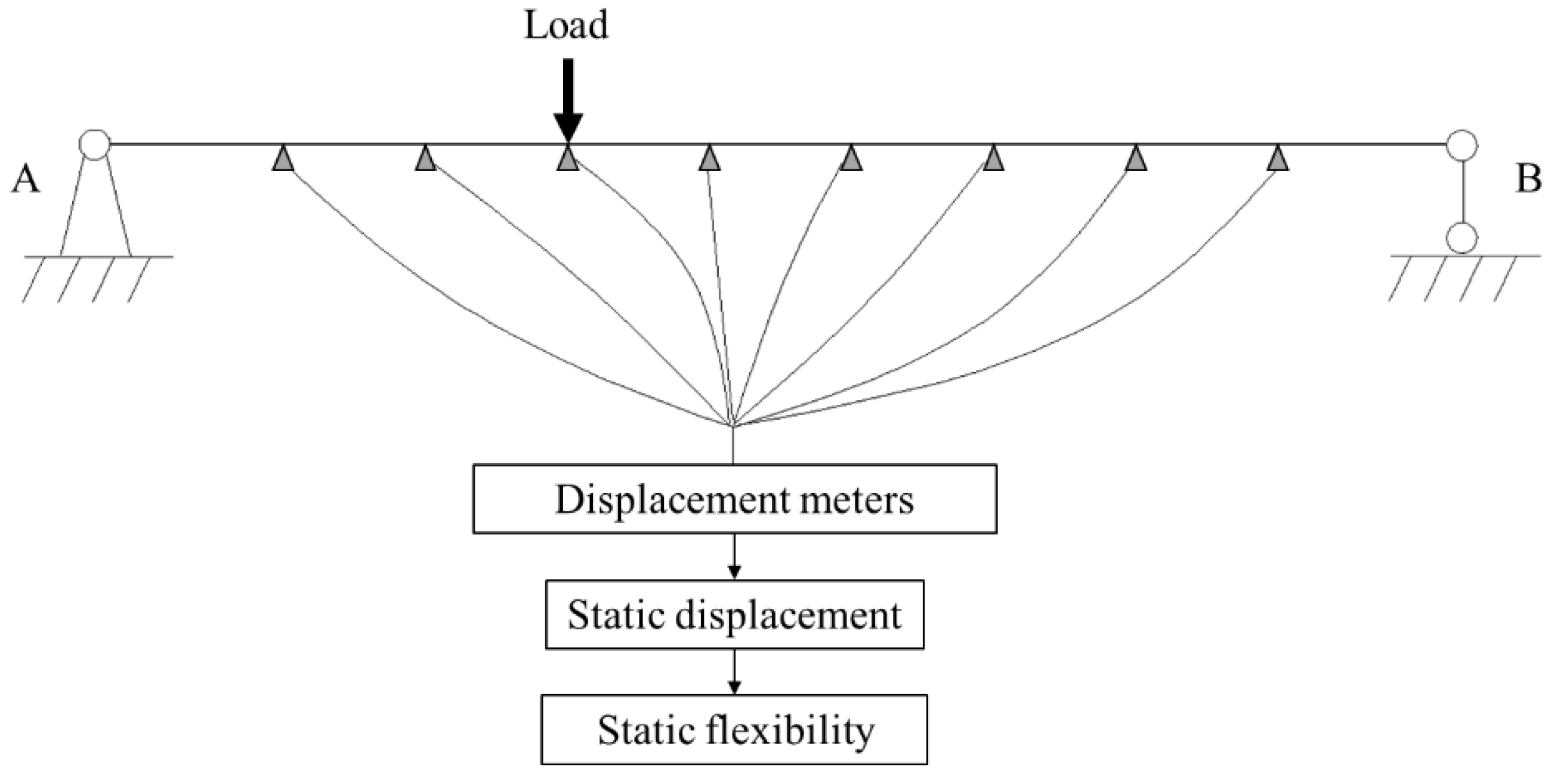
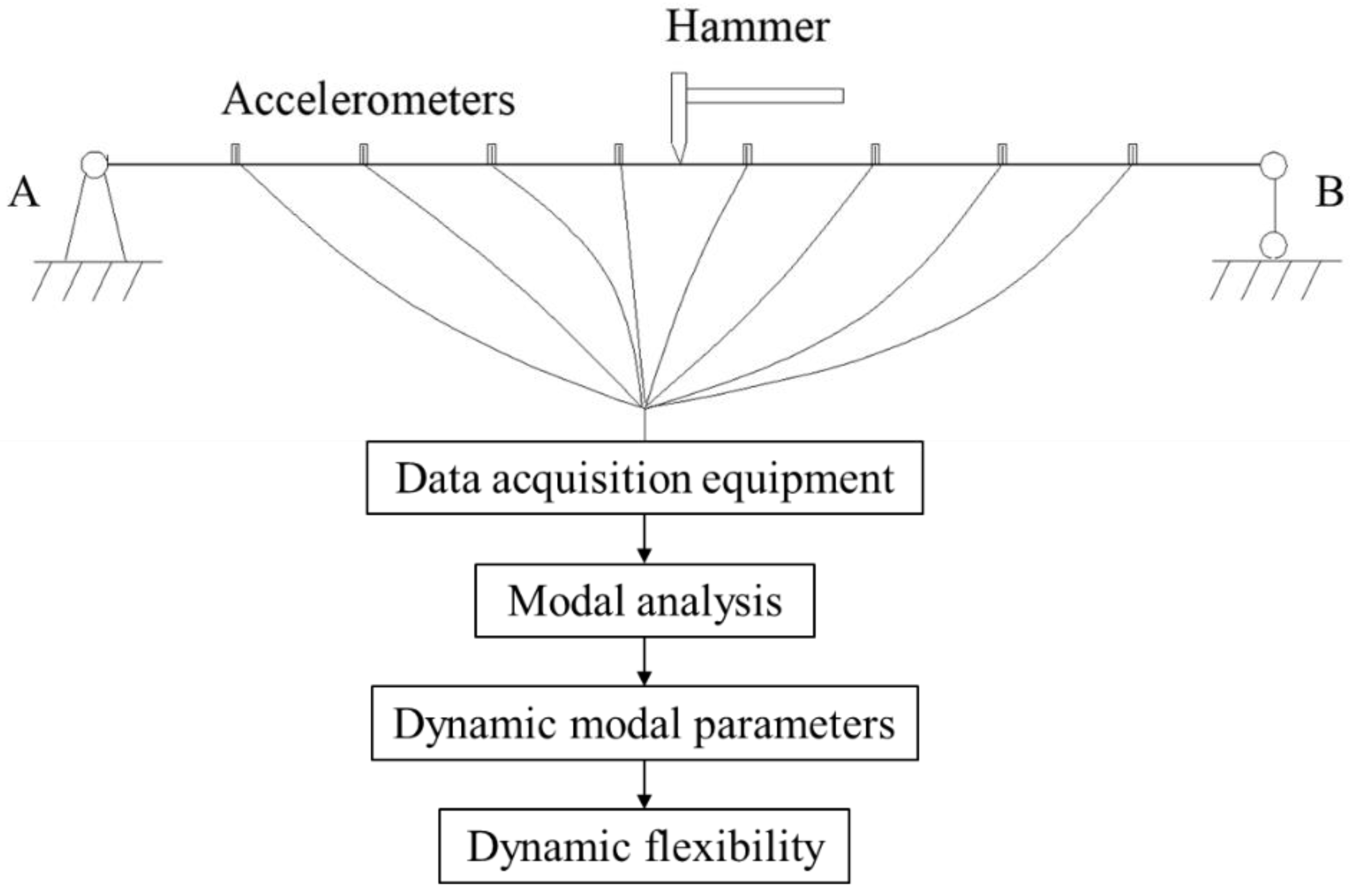
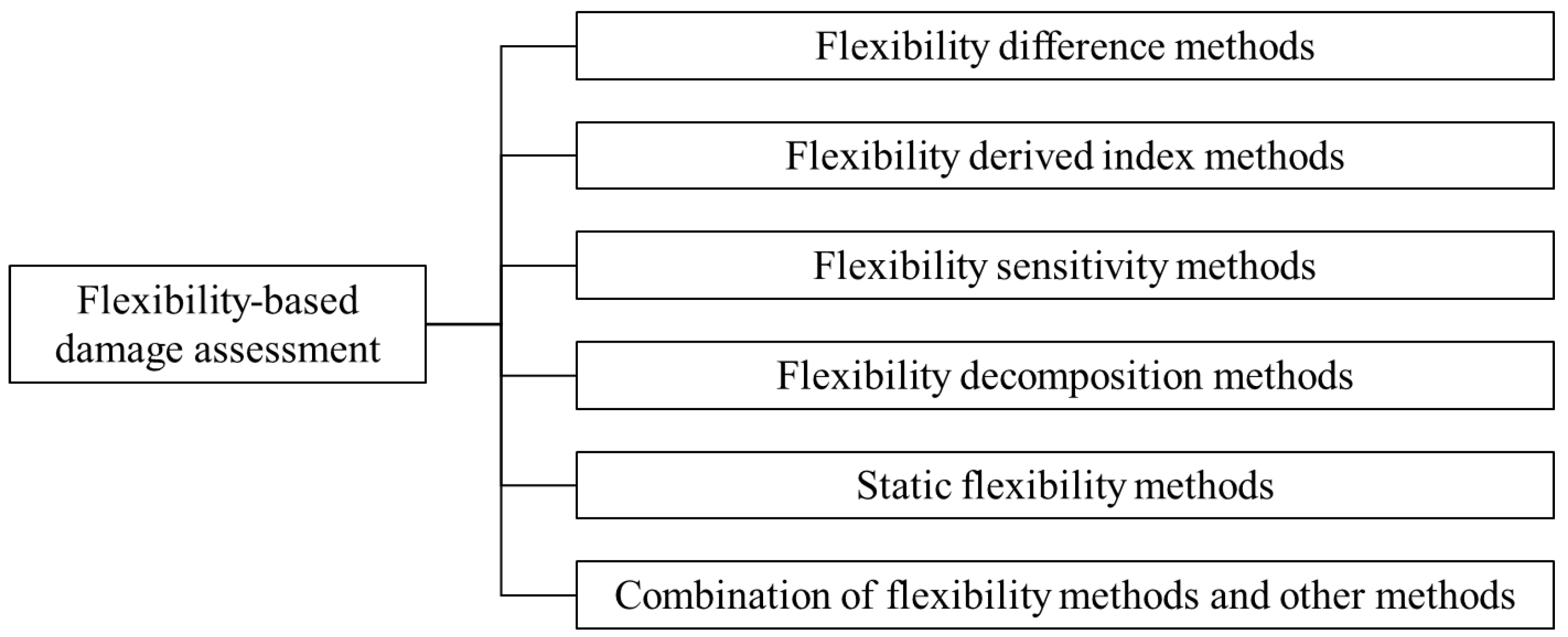
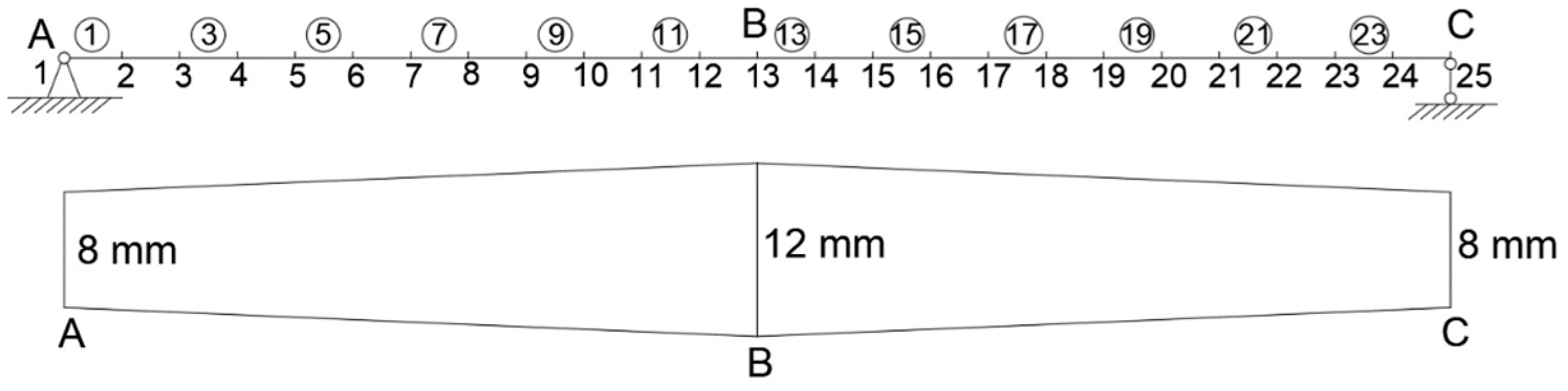
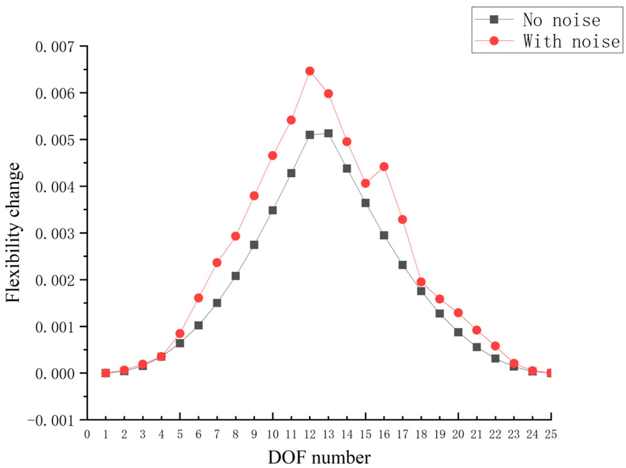
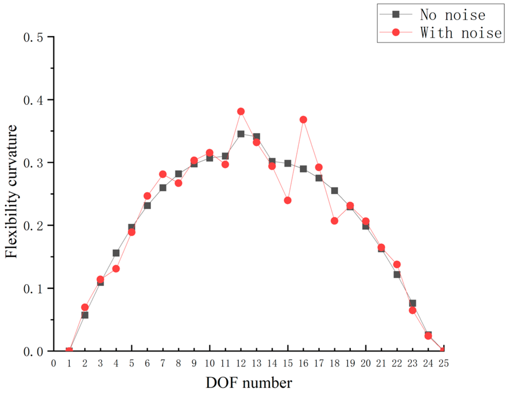
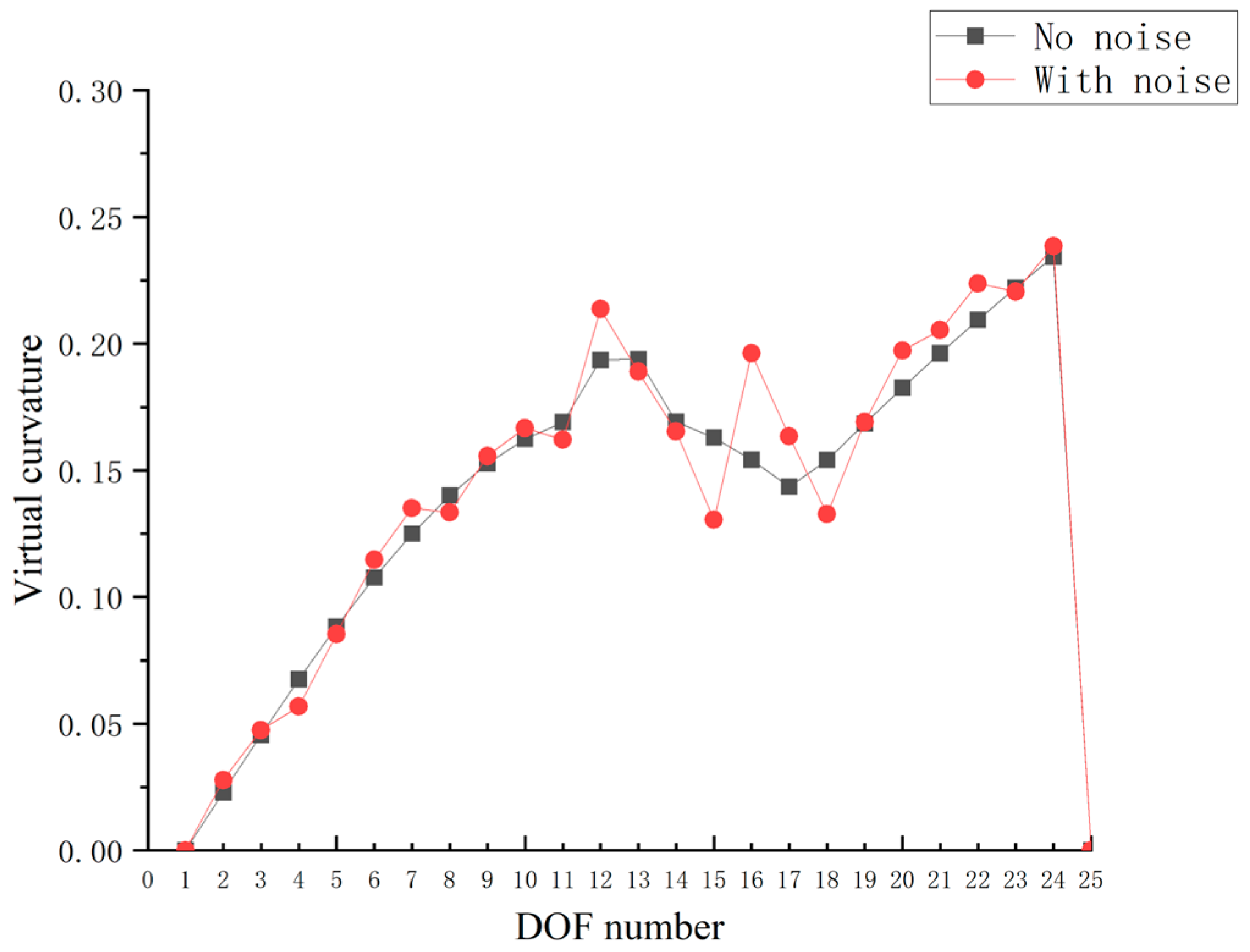
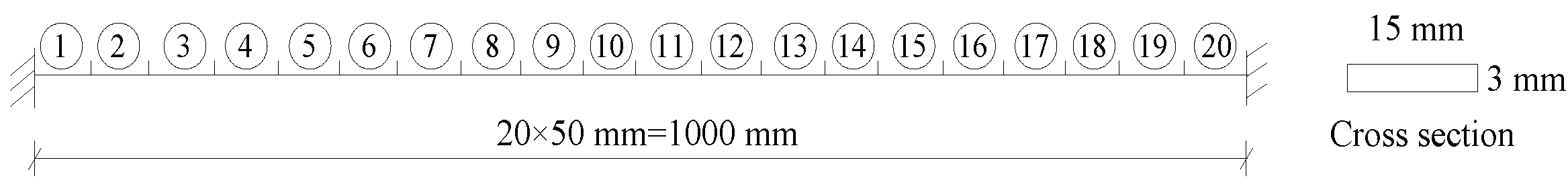
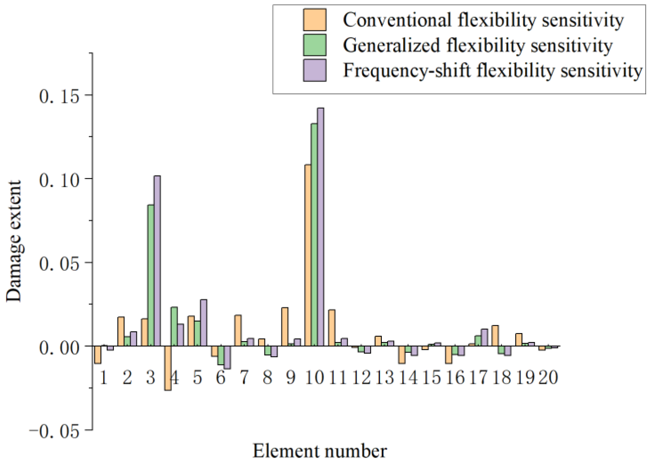
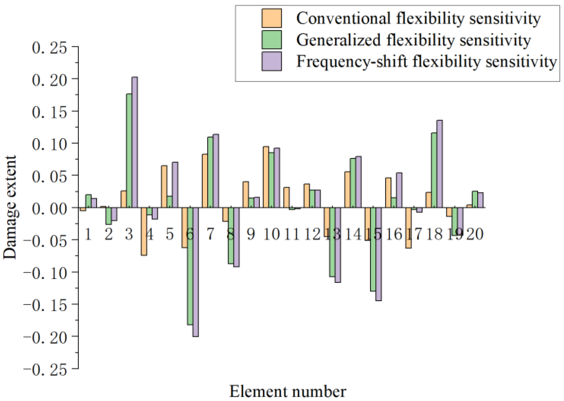
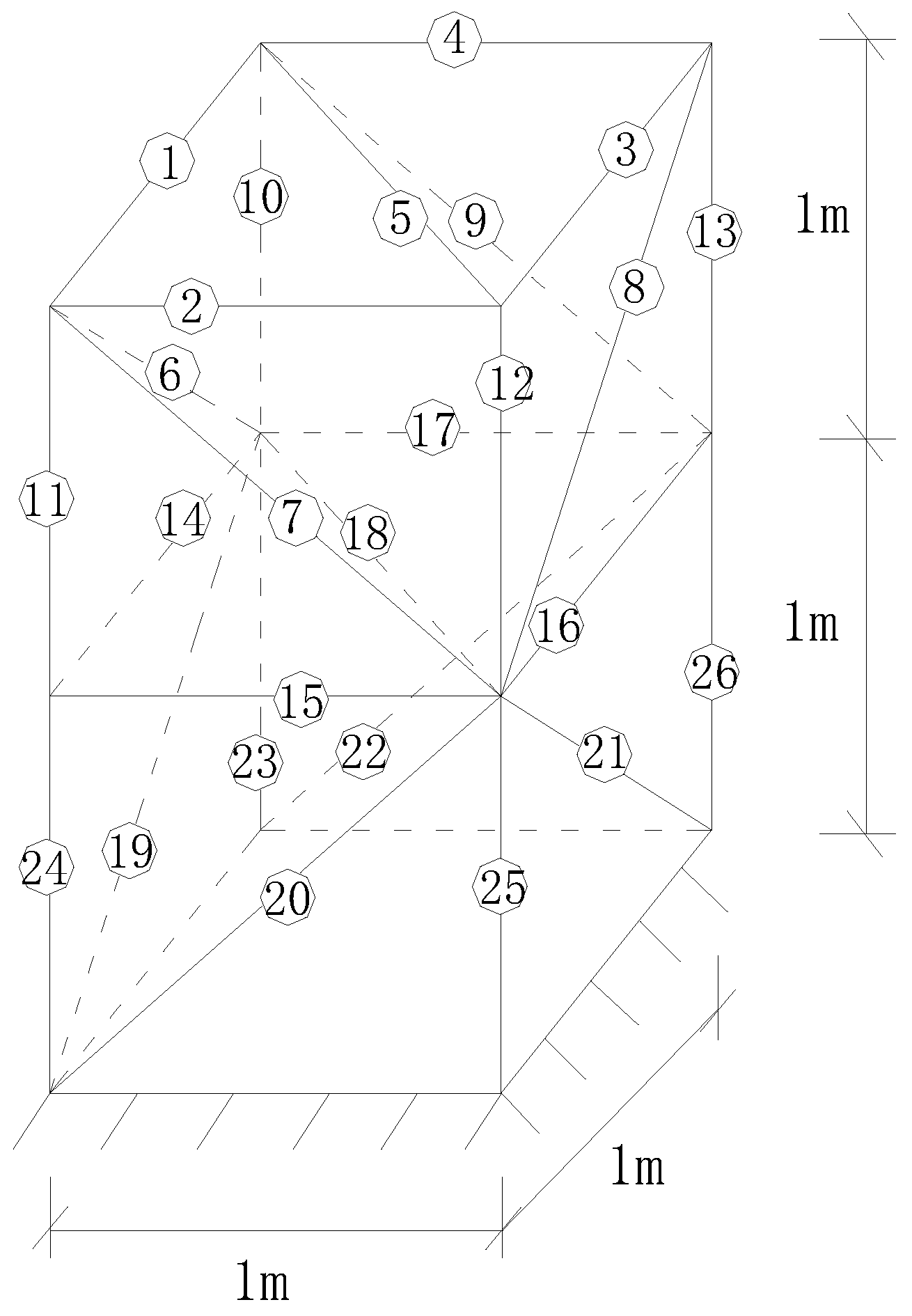
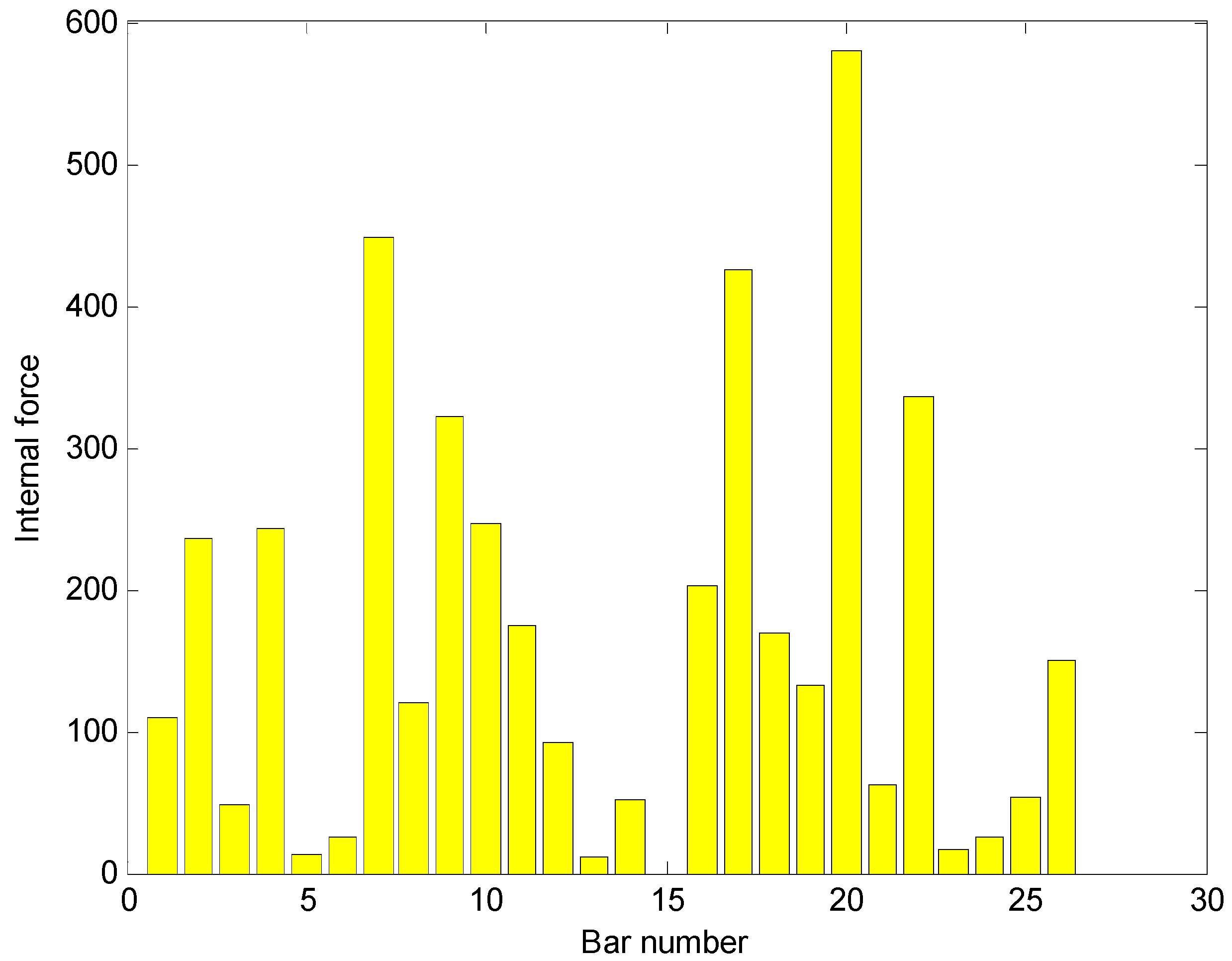
Table 1.
Calculation results obtained using the flexibility difference method (×10−3).
| DOF Number | Flexibility Change | |
|---|---|---|
| No Noise | With Noise | |
| 1 | 0 | 0 |
| 2 | 0.038 | 0.065 |
| 3 | 0.154 | 0.191 |
| 4 | 0.352 | 0.353 |
| 5 | 0.639 | 0.847 |
| 6 | 1.021 | 1.606 |
| 7 | 1.501 | 2.363 |
| 8 | 2.078 | 2.928 |
| 9 | 2.744 | 3.795 |
| 10 | 3.485 | 4.655 |
| 11 | 4.279 | 5.416 |
| 12 | 5.099 | 6.467 |
| 13 | 5.133 | 5.982 |
| 14 | 4.378 | 4.954 |
| 15 | 3.642 | 4.059 |
| 16 | 2.947 | 4.419 |
| 17 | 2.314 | 3.286 |
| 18 | 1.754 | 1.951 |
| 19 | 1.274 | 1.584 |
| 20 | 0.875 | 1.289 |
| 21 | 0.555 | 0.917 |
| 22 | 0.311 | 0.578 |
| 23 | 0.138 | 0.208 |
| 24 | 0.035 | 0.051 |
| 25 | 0 | 0 |
Table 2.
Calculation results obtained using the flexibility curvature method.
| DOF Number | Flexibility Change | |
|---|---|---|
| No Noise | With Noise | |
| 1 | 0 | 0 |
| 2 | 0.057 | 0.069 |
| 3 | 0.109 | 0.114 |
| 4 | 0.156 | 0.131 |
| 5 | 0.197 | 0.189 |
| 6 | 0.231 | 0.247 |
| 7 | 0.260 | 0.281 |
| 8 | 0.282 | 0.267 |
| 9 | 0.298 | 0.303 |
| 10 | 0.307 | 0.315 |
| 11 | 0.310 | 0.297 |
| 12 | 0.345 | 0.381 |
| 13 | 0.341 | 0.332 |
| 14 | 0.302 | 0.294 |
| 15 | 0.299 | 0.240 |
| 16 | 0.290 | 0.368 |
| 17 | 0.275 | 0.292 |
| 18 | 0.255 | 0.207 |
| 19 | 0.229 | 0.231 |
| 20 | 0.199 | 0.207 |
| 21 | 0.163 | 0.165 |
| 22 | 0.122 | 0.138 |
| 23 | 0.076 | 0.065 |
| 24 | 0.026 | 0.024 |
| 25 | 0 | 0 |
Table 3.
Calculation results obtained using the virtual curvature method.
| DOF Number | Flexibility Change | |
|---|---|---|
| No Noise | With Noise | |
| 1 | 0 | 0 |
| 2 | 0.023 | 0.028 |
| 3 | 0.046 | 0.048 |
| 4 | 0.068 | 0.057 |
| 5 | 0.088 | 0.085 |
| 6 | 0.108 | 0.115 |
| 7 | 0.125 | 0.135 |
| 8 | 0.140 | 0.133 |
| 9 | 0.153 | 0.156 |
| 10 | 0.162 | 0.167 |
| 11 | 0.169 | 0.162 |
| 12 | 0.194 | 0.214 |
| 13 | 0.194 | 0.189 |
| 14 | 0.169 | 0.165 |
| 15 | 0.163 | 0.130 |
| 16 | 0.154 | 0.196 |
| 17 | 0.144 | 0.163 |
| 18 | 0.154 | 0.133 |
| 19 | 0.169 | 0.169 |
| 20 | 0.183 | 0.197 |
| 21 | 0.196 | 0.205 |
| 22 | 0.209 | 0.224 |
| 23 | 0.222 | 0.221 |
| 24 | 0.234 | 0.238 |
| 25 | 0 | 0 |
Table 4.
Internal force values obtained through the DLV method using the complete modes (×102, Unit: N).
Table 4.
Internal force values obtained through the DLV method using the complete modes (×102, Unit: N).
| Bar Number | 1 | 2 | 3 | 4 | 5 | 6 | 7 | 8 | 9 | 10 | 11 | 12 | 13 |
|---|---|---|---|---|---|---|---|---|---|---|---|---|---|
| Internal force | 1.097 | 2.365 | 0.480 | 2.429 | 0.136 | 0.247 | 4.489 | 1.207 | 3.225 | 2.467 | 1.745 | 0.917 | 0.109 |
| Bar number | 14 | 15 | 16 | 17 | 18 | 19 | 20 | 21 | 22 | 23 | 24 | 25 | 26 |
| Internal force | 0.515 | 0.000 | 2.021 | 4.253 | 1.687 | 1.317 | 5.796 | 0.618 | 3.366 | 0.166 | 0.260 | 0.541 | 1.497 |
Disclaimer/Publisher’s Note: The statements, opinions and data contained in all publications are solely those of the individual author(s) and contributor(s) and not of MDPI and/or the editor(s). MDPI and/or the editor(s) disclaim responsibility for any injury to people or property resulting from any ideas, methods, instructions or products referred to in the content. |
© 2023 by the authors. Licensee MDPI, Basel, Switzerland. This article is an open access article distributed under the terms and conditions of the Creative Commons Attribution (CC BY) license (https://creativecommons.org/licenses/by/4.0/).
Share and Cite
MDPI and ACS Style
Peng, X.; Yang, Q.; Qin, F.; Sun, B. Structural Damage Detection Based on Static and Dynamic Flexibility: A Review and Comparative Study. Coatings 2024, 14, 31. https://0-doi-org.brum.beds.ac.uk/10.3390/coatings14010031
AMA Style
Peng X, Yang Q, Qin F, Sun B. Structural Damage Detection Based on Static and Dynamic Flexibility: A Review and Comparative Study. Coatings. 2024; 14(1):31. https://0-doi-org.brum.beds.ac.uk/10.3390/coatings14010031
Chicago/Turabian StylePeng, Xi, Qiuwei Yang, Fengjiang Qin, and Binxiang Sun. 2024. "Structural Damage Detection Based on Static and Dynamic Flexibility: A Review and Comparative Study" Coatings 14, no. 1: 31. https://0-doi-org.brum.beds.ac.uk/10.3390/coatings14010031
Note that from the first issue of 2016, this journal uses article numbers instead of page numbers. See further details here.