Performance Investigation of an Exhaust Thermoelectric Generator for Military SUV Application


1
Agricultural Mechanical Engineering Research and Design Institute, Hubei University of Technology, Wuhan 430068, China
2
School of Automation, Wuhan University of Technology, Wuhan 430070, China
3
School of Automobile Engineering, Wuhan University of Technology, Wuhan 430070, China
*
Author to whom correspondence should be addressed.
Coatings 2018, 8(1), 45; https://0-doi-org.brum.beds.ac.uk/10.3390/coatings8010045
Submission received: 4 December 2017
/
Revised: 16 January 2018
/
Accepted: 17 January 2018
/
Published: 22 January 2018
(This article belongs to the Special Issue Novel Thin Film Materials for Thermoelectric Applications)
Abstract
:To analyze the thermoelectric power generation for sports utility vehicle (SUV) application, a novel thermoelectric generator (TEG) based on low-temperature Bi2Te3 thermoelectric modules (TEMs) and a chaos-shaped brass heat exchanger is constructed. The temperature distribution of the TEG is analyzed based on an experimental setup, and the temperature uniformity optimization method is performed by chipping peak off and filling valley is taken to validate the improved output power. An automobile exhaust thermoelectric generator (AETEG) using four TEGs connected thermally in parallel and electrically in series is assembled into a prototype military SUV, its temperature distribution, output voltage, output power, system efficiency, inner resistance, and backpressure is analyzed, and several important influencing factors such as vehicle speed, clamping pressure, engine coolant flow rate, and ambient temperature on its output performance are tested. Experimental results demonstrate that higher vehicle speed, larger clamping pressure, faster engine coolant flow rate and lower ambient temperature can enhance the overall output performance, but the ambient temperature and coolant flow rate are less significant. The maximum output power of AETEG is 646.26 W, the corresponding conversion efficiency is 1.03%, and the increased backpressure changes from 1681 Pa to 1807 Pa when the highest vehicle speed is 125 km/h.
1. Introduction
Continuously updated development of green energy techniques is a good alternative to resolve global energy crisis and environmental protection. Owing to several advantages such as having little vibration, being highly reliable and durable, and having no moving parts, there have been considerable emphases on the development of thermoelectric modules (TEMs) for a variety of photovoltaic, automotive, military and aerospace applications over the past years [1,2,3,4]. With the rapid development of economy and society, automobiles have become a necessity. For the internal combustion engine used in traditional automobiles, only about 25% of its fuel energy is converted to mechanical energy, whereas approximately 40% of the fuel energy is wasted through exhaust gas, 30% is dissipated in the engine coolant, apart from friction and parasitic losses [5]. Thus, recovery of exhaust heat energy via thermoelectric technology for use in the vehicle system is important and can significantly enhance both fuel economy and system performance. To achieve this goal, use of thermoelectric generators (TEGs) based on single, low, and intermediate temperature TEMs has been a novel research focus [6]. Since the first automobile exhaust thermoelectric generator (AETEG) emerged in 1963, in the open literature, many research groups have made great efforts to install the TEMs in automobile exhaust pipes to study the potential use of TEG systems in exhaust gas heat recovery. For instance, Hi-Z technology began the development in 1991 of AETEG system to recover the exhaust wasted heat, but it can generate only 126.6 W of electrical power from the Cummins L-10 engine exhaust [7]. In 1998, Nissan constructed the first TEG based on Si-Ge elements for automobiles [8]. The Bell Solid State Thermoelectrics (BSST) team developed a high-efficiency thermoelectric waste energy recovery system for passenger vehicle applications in 2004 [9]. In 2007, Thacher et al. [10] analyzed the performance of an exhaust-mounted TEG in a truck, whereas it generated about 180 W of electrical energy at 113 km/h. Hussain et al. [11] tested a TEG in a 2.5 L gas–electric hybrid vehicle in 2009, about 300 W of electrical energy was obtained under US Environmental Protection Agency (EPA) highway drive cycle conditions. Hsu et al. [12] constructed a TEG mounted with eight Bi2Te3 TEMs and employed eight air-cooled heat-sink assemblies, obtaining a maximum output power of 44 W in 2011. Kim et al. [13] recovered a maximum of 350 W using some heat pipes in TEG systems as a heat sink based on Bi2Te3 TEMs in 2011. Liu et al. [14] proposed a prototype TEG whose maximum power was about 250 W when the hot side temperature was 473 K.
Review of the above literature shows that the development of various TEGs for vehicles application based on experimental setup is in progress. However, very a few works focus on the road test performance based on real vehicle after 2010. According to the above research achievements, the maximum power of most of the TEGs is almost below 400 W, which cannot meet the electrical requirements (usually above 600 W) for automotive applications such as turn signals, stop lamps, electric windows, air conditioners, seat heaters, etc. To enhance the maximum power and improve the AETEG, a number of studies have shown that well-designed inner topology of heat exchanger contributes to the efficient heat transfer and large temperature difference [15,16,17,18,19,20,21], and the optimized design of heat sink (cold side) [22] and geometry of TEMs [23,24,25] is also significant. In our previous work, we had designed various heat exchangers, including maze-shaped, fishbone-shaped, chaos-shaped and dimple-shaped heat exchangers, to analyze their thermal characteristics. Su et al. [26] proposed fishbone-shaped heat exchangers and tested their acoustic characteristics, and finally chose a “fishbone” finned internal structure with 12 mm interior thickness. Liu et al. [27] discussed the thermal performance of heat exchangers with different internal structures and thickness and concluded that a plate-shaped heat exchanger with chaos-shaped internal structure and thickness of 5 mm achieves a relatively ideal thermal performance. Wang et al. [28] assessed the influence of different fin distributions of a heat exchanger on the temperature uniformity and the pressure drop in AETEG, and firstly used the dimples in the heat exchanger, the simulated results showed that the heat transfer could be enhanced and the backpressure quite low [29].
Different types of heat exchanger have been constructed, the heat uniformity and the overall output power have been improved after optimization since 2010, the lack of comprehensive performance evaluation regarding thermoelectric efficiency, generation capacity, temperature distribution, inner resistance, backpressure of AETEG and their significant influence factors in both test bench and real prototype vehicle need to be further evaluated. Based on previously reported results [30], the main objective of the present study is to comprehensively investigate the road test performance characteristics of AETEG assembled into a prototype military sports utility vehicle (SUV) due to its large chassis space based on the performance analysis of TEG with experimental setup, including maximum output power, output voltage, conversion efficiency, temperature distribution, inner resistance, backpressure, and the influences of different SUV speeds, clamping pressures, coolant flow rates, ambient temperatures as well as temperature uniformity of heat exchangers on the maximum output power and conversion efficiency were discussed in the further work.
2. Experimental Setup of a TEG System
2.1. TEG Architecture
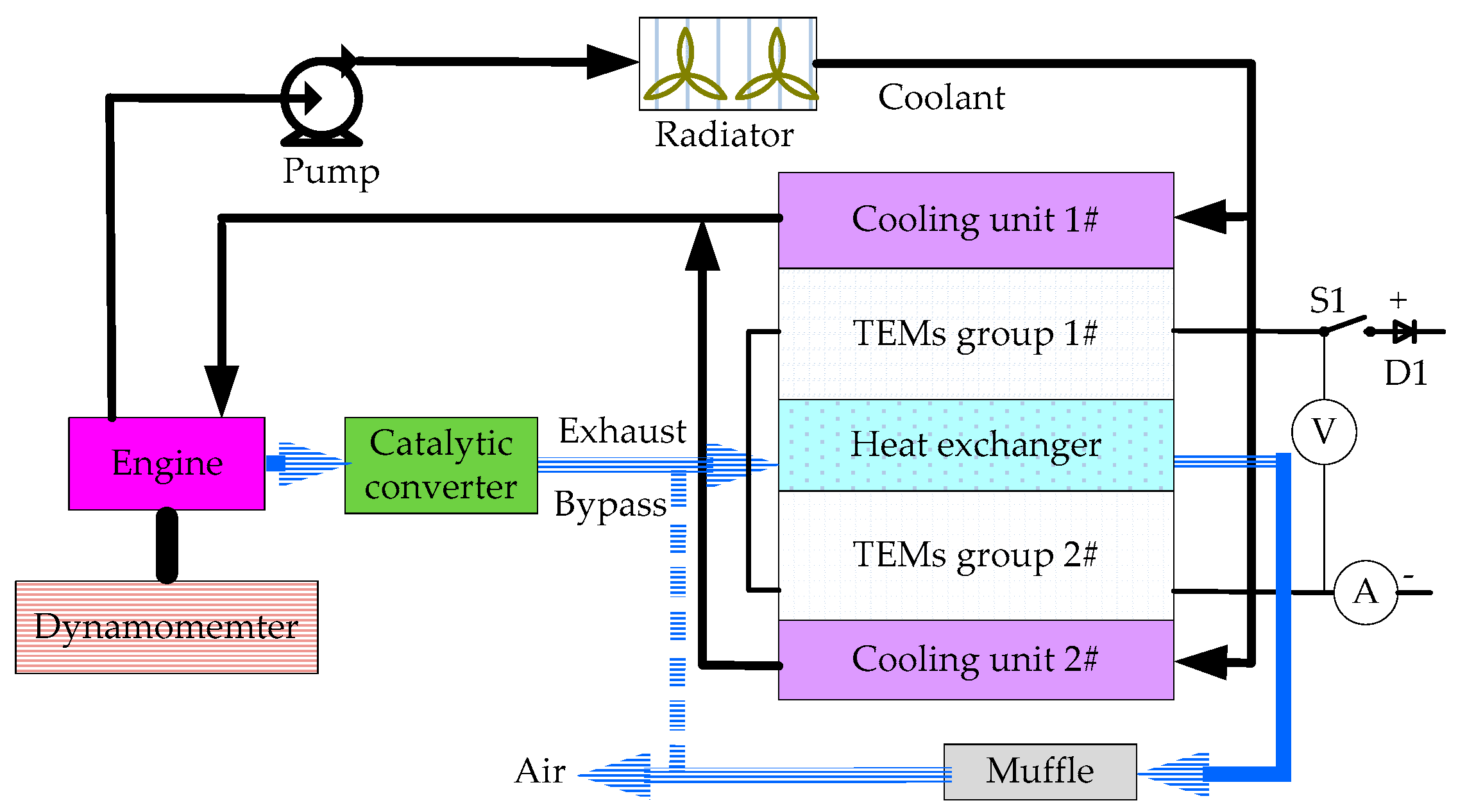
The schematic diagram of an experimental setup of TEG used to recover the engine waste heat is shown in Figure 1. A dynamometer is adopted to simulate the driving cycles of vehicles by adjusting the operation conditions of engine such as torque and revolution rate. Once the engine works, exhaust gas flows into the heat exchanger to provide hot side temperature, and the engine cooling water is pumped into each cooling box to form the cold side. Thus, electricity is generated due to the temperature difference between the hot side and cold side of each TEM. For the engine coolant temperature is around 90 °C, the temperature difference of each TEM is proportional to its hot side temperature. To obtain higher temperature difference in experimental setup, the radiator can be controlled to precool the inlet coolant of cooling units.
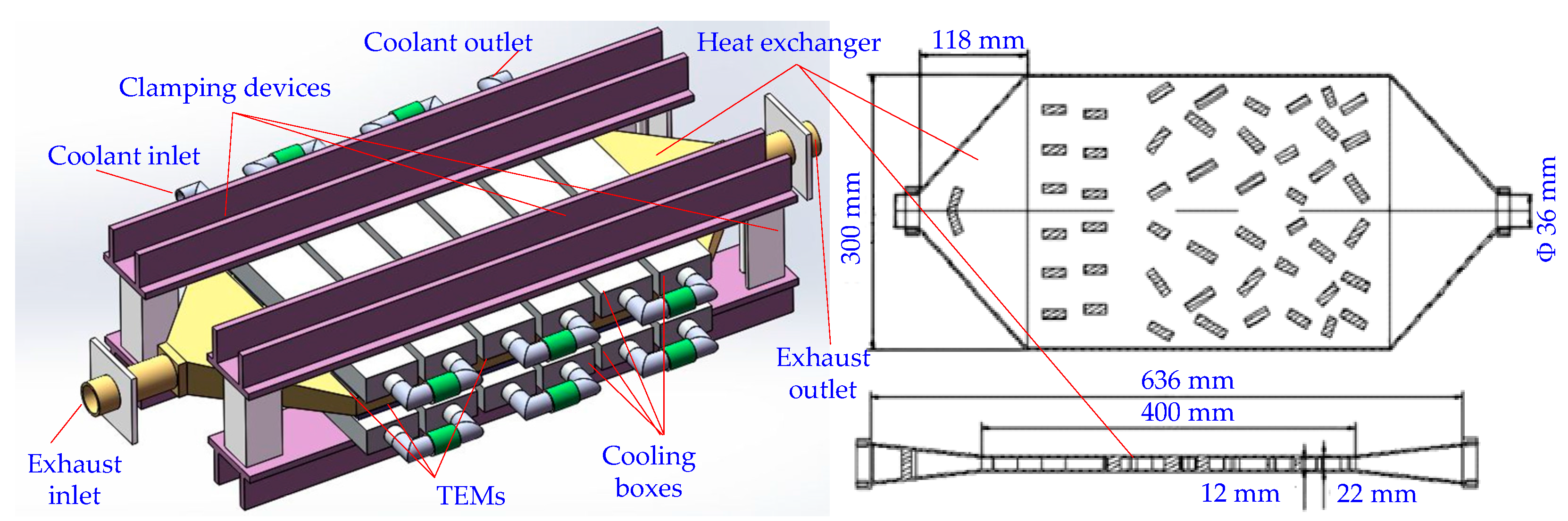
The specific TEG as illustrated in Figure 2 consists of TEMs, brass heat exchanger, cooling units, engine, catalytic converter, and so on. All the TEMs are sandwiched between both two surfaces of a heat exchanger connected to engine exhaust pipe and cooling units consisting of six pairs of water tanks called single-row cooling boxes, and they are clamped with adjustable force using four concave type steel and torque wrench. In total, there are 60 TEMs of Bi2Te3-based materials arranged on both surfaces of the heat exchanger in six rows, i.e., five TEMs in each row are fixed with a common water tank. All the water tanks of each TEG are connected in series.
Furthermore, to guarantee uniform temperature distribution and improve the heat transfer performance, a chaos-shaped heat exchanger [27] is adopted, and its effective heat transfer size is 400 mm in length and 300 mm in width. For each cooling unit above one surface of the heat exchanger, six single-row cooling boxes are connected in series for the sake of convenient assembly. The relevant parameters of the principal components of the experimental setup are listed in Table 1. For the maximum operating temperature of conventional Bi2Te3 TEM is 200–250 °C, in this study, the adopted Bi2Te3 TEMs are manufactured by Thermonamic Electronics (Jiangxi, China) Corp. Ltd., the high conductivity graphite paper whose maximum operating temperature is 400 °C is used as the thermally conductive interface material of Bi2Te3 TEM.
2.2. Temperature Distribution
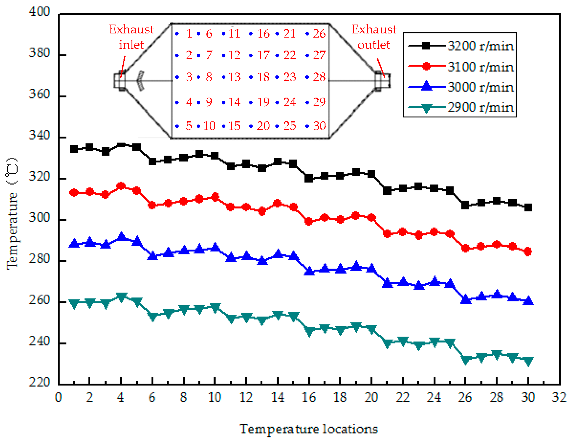
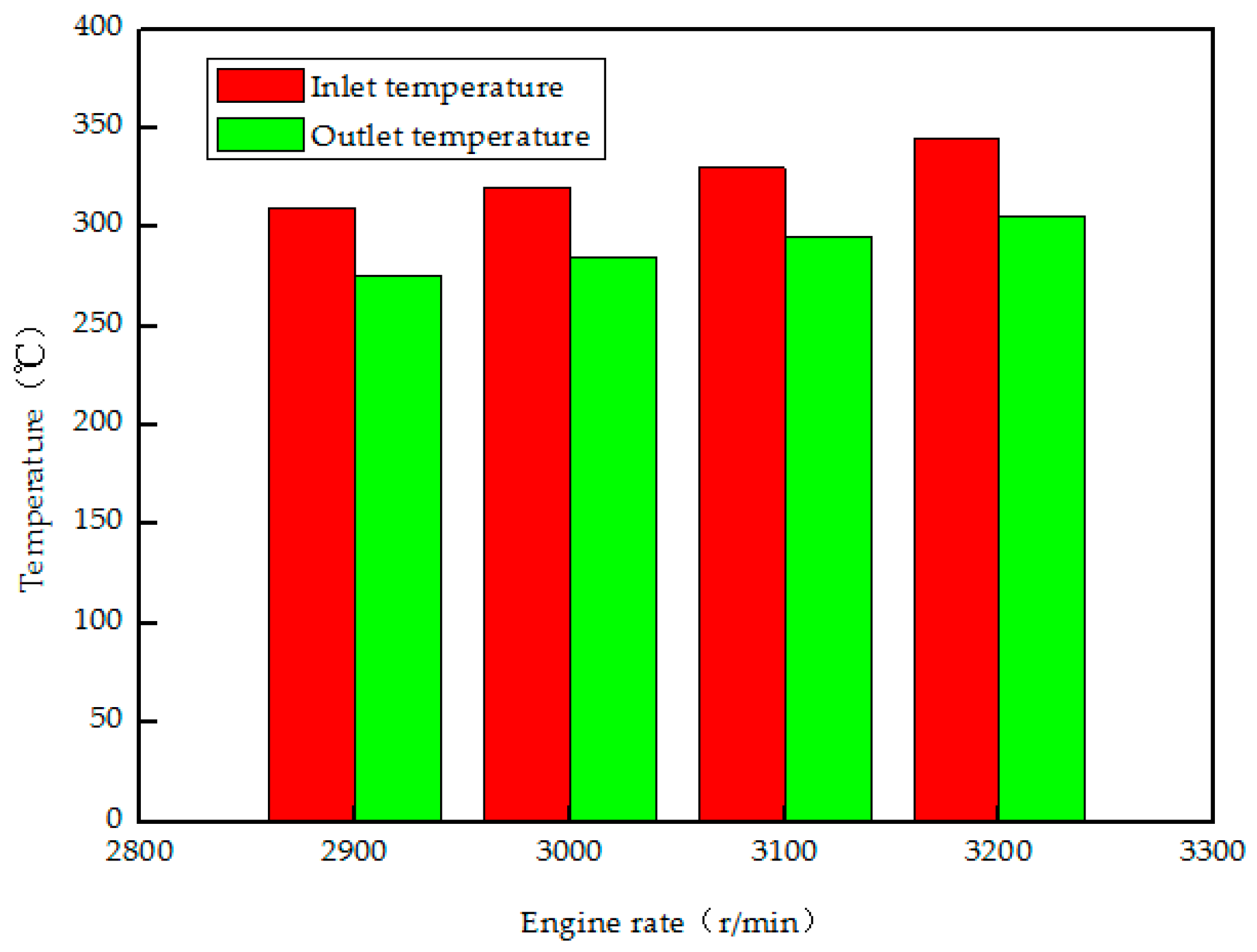
The performance of TEM is influenced by the temperature difference between its hot side and cold side, for the experimental setup of TEG presented in Figure 1, the cooling units of TEG is connected to the engine cooling system with coolant temperature being about 90 °C, the temperature difference is mainly affected by the surface temperature of heat exchanger. Considering the maximum operating temperature of TEM is 350 °C and the symmetrical structure of the chaos-shaped heat exchanger, the surface temperature distribution of temperature locations corresponding to the top 30 TEMs with different engine revolution rates is shown in Figure 3. The corresponding inlet and outlet temperature of the heat exchanger is provided in Figure 4.
With the increasing of engine revolution rates, the temperature of the top 30 locations, inlet, and outlet gas of heat exchanger increased, the temperature of front rows is much higher than that of rear rows, and the central zone is slightly higher than that of marginal area. The temperature difference between inlet and outlet gas temperature increases from 31 °C (2900 r/min) to 40 °C (3200 r/min). When the engine revolution rate is 3200 r/min, the inlet temperature is 350 °C, the outlet temperature is 310 °C, the maximum temperature of all the top 30 temperature locations is 337 °C (No. 4 location), while the minimum temperature is 303 °C (No. 30 location). Thus, to protect TEMs from burning out due to long-playing high temperature, the maximum engine revolution rate is limited to 3200 r/min.
2.3. Influence of Temperature Uniformity
For a single TEM, its internal resistance (denoted Rm) can be expressed as follows [30]:
where lp, σp, Ap are the leg length (m), electricity resistivity (Ωm) and cross-sectional area (m2) of a p-type semiconductor galvanic arm, respectively, n is the semiconductor pairs number, while ln, σn, An are the leg length, electricity resistivity and cross-sectional area of an n-type semiconductor galvanic arm, respectively. σp and σn can be treated as constants during a long time when the working condition is stable.
Rm = nlp/(σpAp) + nln/(σnAn)
For the open-circuit voltage (denoted Voc) of a single TEM, it can be described in Equation (2) [30].
where αPN is the relative Seebeck coefficient (V/K), αp and αn are the Seebeck coefficients of the p-type and n-type semiconductor galvanic arms, respectively. TH and TL are the hot side and cold side temperature (K), respectively.
Voc = nαPN(TH − TL) = n (αp − αn)(TH − TL)
When several TEMs are electrically connected in series (N denotes the number), the overall open-circuit voltage (denoted Uoc) and internal resistance (denoted R) are given in Equations (3) and (4), respectively, and the practical output power (denoted Pout) is calculated in Equation (5) when external load resistance (denoted RL) is connected to its overall output port. Basic circuit theory demonstrated that the output power of the TEMs (denoted Pmax) reaches their maximum value when the external load resistance is equal to their inner resistance [31], Pmax can be calculated using Equation (6).
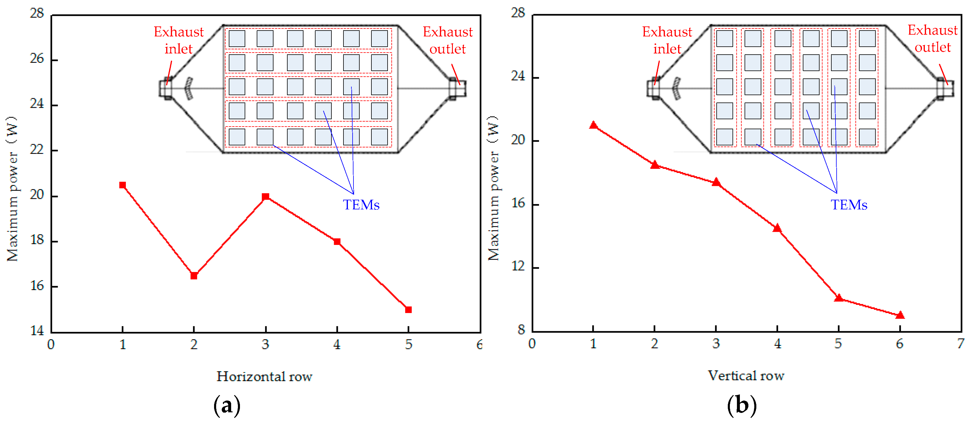
The maximum power of five TEMs in series of each vertical row and six TEMs in series of each horizontal row is shown in Figure 5 (the engine revolution is 3200 r/min, the clamping pressure is 300 kg/m2, and the coolant flow rate is 9.27 L/min). The maximum power of the front three vertical rows TEMs is much larger than that of the rear three vertical rows, and maximum power of the middle horizontal rows is more than other rows due to the gas flow gathering in both the middle and front area of the chaos-shaped heat exchanger. The maximum power sum of the rear two vertical rows TEMs is only 19.1 W, while the one of the front four vertical rows TEMs is 71.4 W. Thus, if the number of TEMs in the vertical rows is increased from four to six, the maximum output power is improved by 21.1%, but the overall volume and weight will be increased by about 30%. Moreover, one of the worst possible situations is that when the maximum hot side temperature of TEM is very close to its maximum heat resistance (350 °C), and the minimum hot side temperature of TEM is less than 300 °C or even lower, the thermoelectric potentials of those TEMs with smaller temperature difference due to their lower hot side temperature is restricted.
Even though the surface temperature distribution of the chaos-shaped heat exchanger is more superior to that of the fish-bone-shaped one, based on both Figure 3 and Figure 5, the unsatisfactory surface temperature distribution of heat exchanger still needs ongoing optimization of the inner topology. To make full use of the thermoelectric generation potential of each TEM, the hot side temperature uniformity should be improved as much as possible based on current the chaos-shaped heat exchanger.
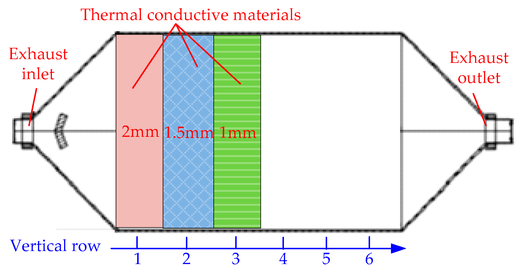
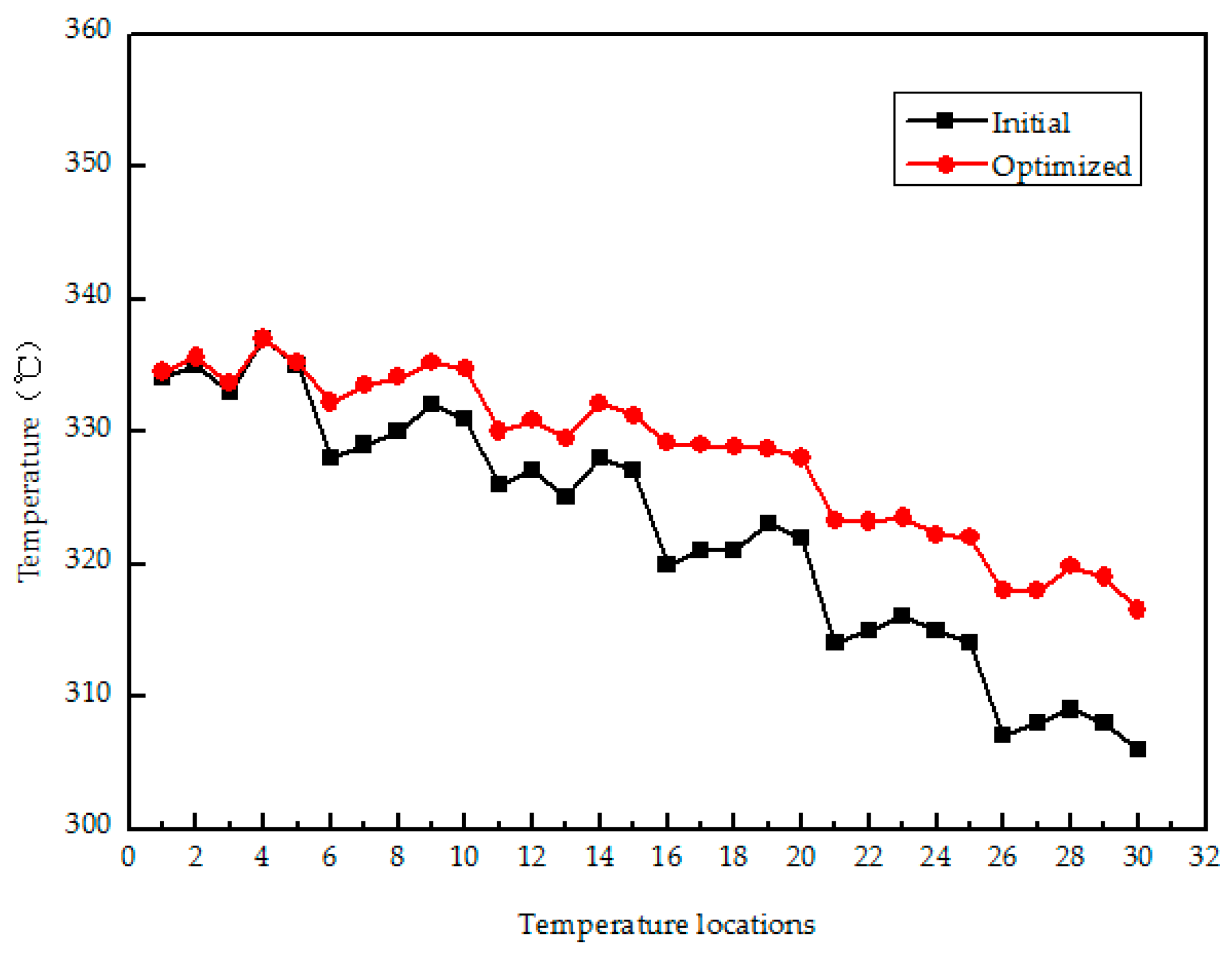
As shown in Figure 6, the surface of the front three vertical rows is covered with high-performance thermal conductive material of large temperature resistance (above 450 °C) whose thermal conductivity is about 3 W/(mK) and thickness is 2 mm, 1.5 mm, 1 mm, respectively. On this occasion, the engine revolution rate is increased to be 3310 r/min until the maximum temperature of the 30 temperature locations is equal to the initial case (337 °C), and the surface temperature distribution comparison of temperature locations is shown in Figure 7. The surface temperature corresponding to the rear two vertical rows is higher after optimization than that of the initial heat exchanger without any covered thermal conductive materials, the minimum temperature (315 °C) is increased by 12 °C compared with that of the initial heat exchanger, and the maximum temperature difference among the 30 temperature locations is within 22 °C.
Figure 8 shows the maximum output power of vertical and horizontal rows of TEMs of the two distributions when the maximum temperature of all the 30 temperature locations is 337 °C after the temperature uniformity is optimized above. The maximum output power sum of the vertical and horizontal rows of TEMs are 108.3 W and 104.5 W, respectively, compared with that of initial heat exchanger (100.1 W in Figure 5a and 98.2 W in Figure 5b), they are increased by 7.2% and 6.4%, respectively. Thus, the overall maximum output power of TEG can be slightly enhanced when the surface temperature uniformity is improved with the method of chipping peak off and filling valley up according to the temperature locations above, but higher engine revolution rate and larger amount of exhaust flow are needed, which requires much larger output power of engine and sacrifice the exhaust waste heat recovery efficiency.
3. Road Test of AETEG System
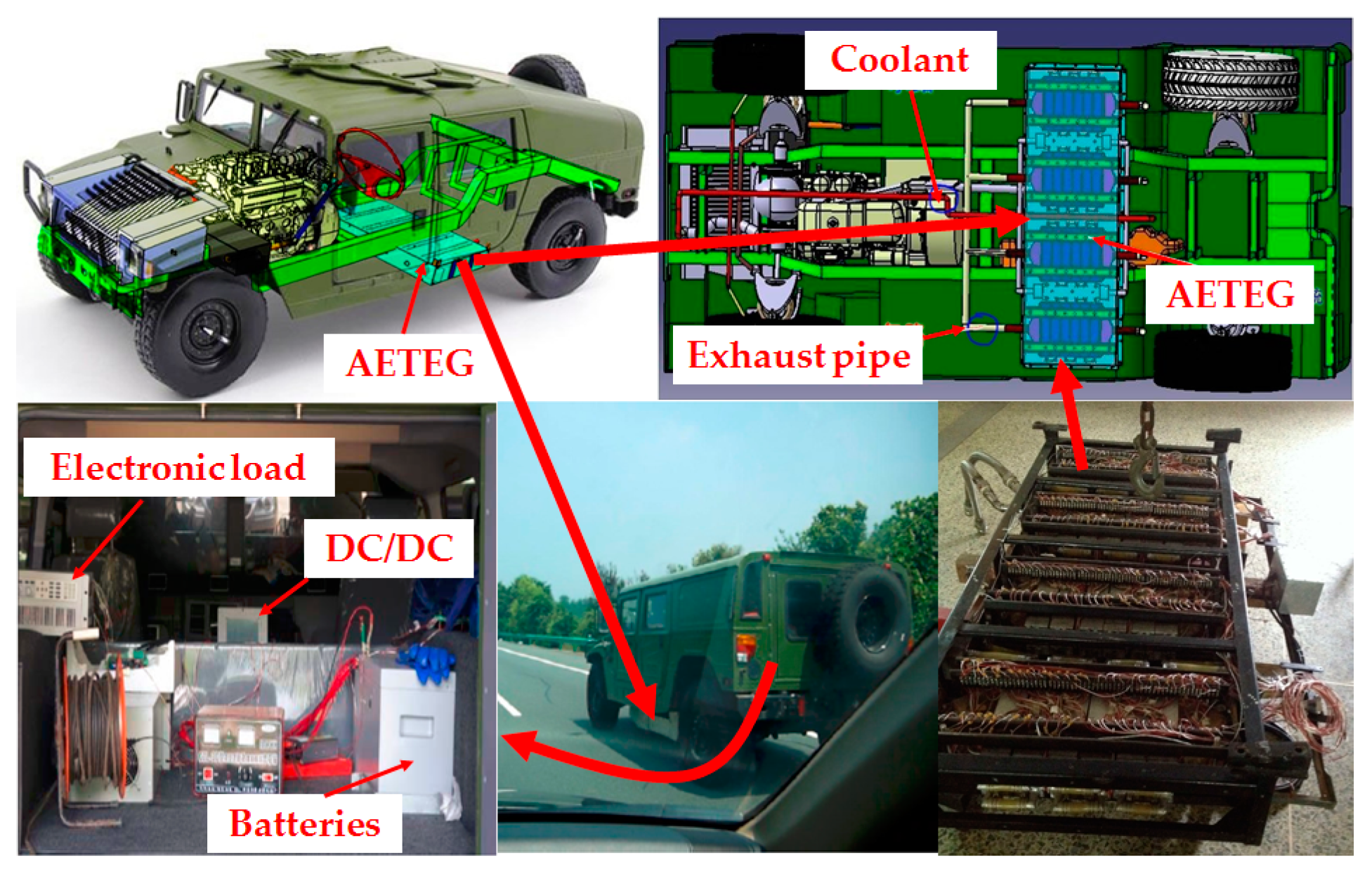
Considering the wide space under the chassis of prototype military SUV, as shown in Figure 9, an AETEG system with four above TEGs thermally connecting in parallel (i.e., all the inlets of four heat exchangers and cooling system of each TEG are connected in parallel) and electrically connecting in series is constructed, it includes 240 single TEMs in total, its dimensions are 1420 mm × 670 mm × 185 mm, and its terrain clearance is 315 mm. For the cooling system, a branch circle of engine coolant is adopted without pump and radiator for the sake of saving installation space and reducing extra consumed power.
According to the analysis results based on experimental setup above, the temperature uniformity of the front three vertical rows during each heat exchanger is optimized by the method of chipping peak off and filling valley up shown in Figure 6, the inlet and outlet temperatures of both four above heat exchangers and cooling systems are detected with K-type thermocouple. To reduce system complexity, only the maximum and minimum temperature locations are selected to evaluate the temperature difference. The road test is carried out on the “Wuhan–Huangshi” highway of China whose maximum speed limitation is 120 km/h, the main parameters of SUV are listed in Table 2.
3.1. Influence of SUV Speed
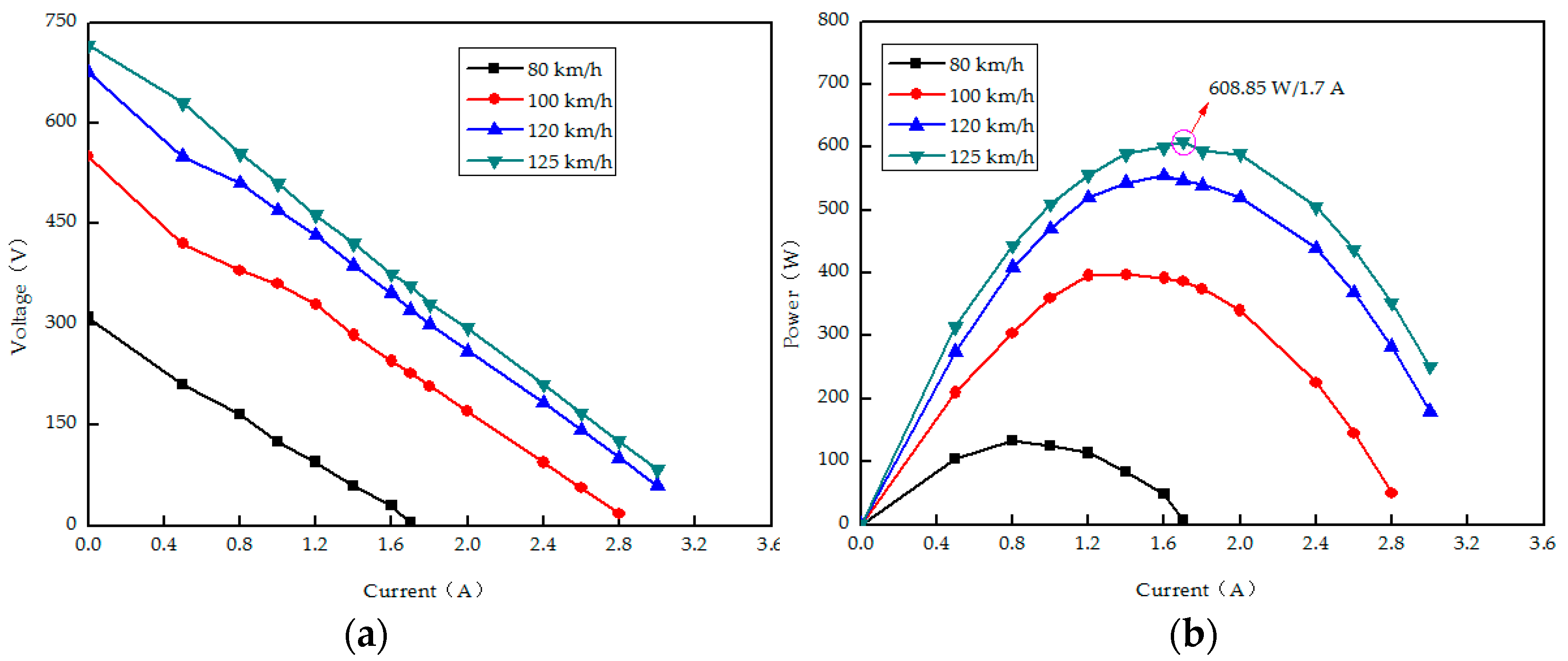
To ensure a large amount of absorbed heat for AETEG, considering the highest speed limitation on the highway of China, the specific SUV speed was used in the test as follows: working condition 1: SUV speed, 80 km/h; engine rotation speed, 1600 r/min; engine power, 19 kW; working condition 2: SUV speed, 100 km/h; engine rotation speed, 2000 r/min; engine power, 30 kW; working condition 3: SUV speed, 120 km/h; engine rotation speed, 2400 r/min; engine power, 42 kW; working condition 4: SUV speed, 125 km/h; engine rotation speed, 2500 r/min; engine power, 47 kW. Figure 10 shows the measured characteristics curves of output voltage and power versus current with different SUV speeds when the ambient temperature was 25 °C, the clamping pressure is 300 kg/m2, and the engine coolant flow rate is 40.8 L/min. It is obvious that the output voltage and power are in direct proportion to SUV speeds, increased both output voltage and power with the same external load are accompanied with the augment of SUV speeds. When the highest SUV speed is 125 km/h, the measured maximum power of AETEG is 608.85 W, and its corresponding current is 1.7 A.
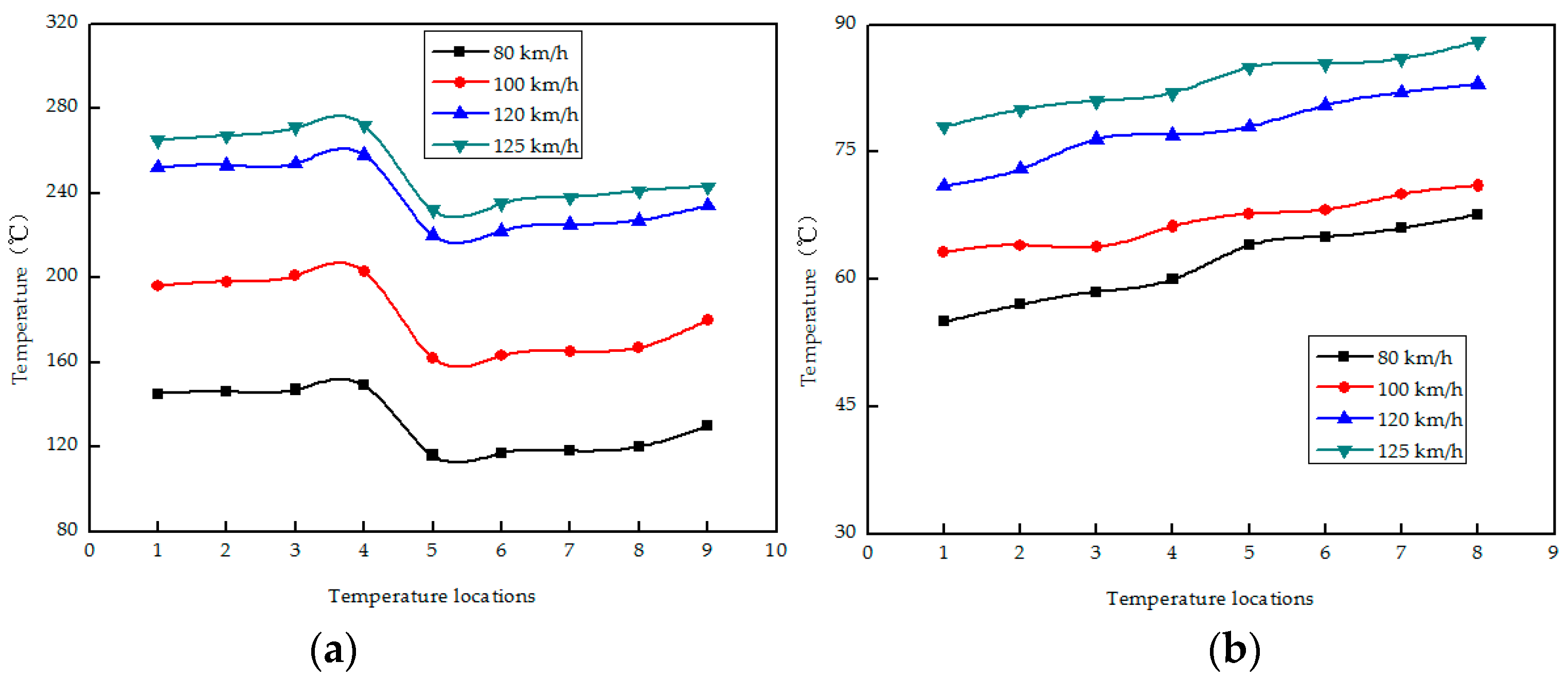
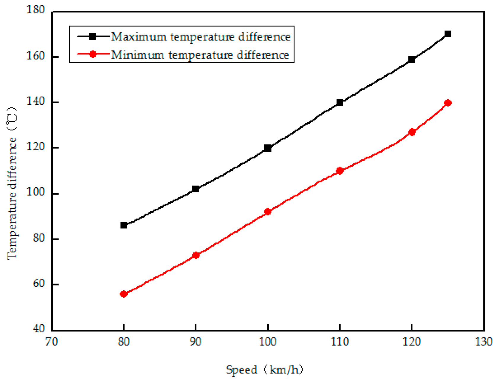
Figure 11 shows both the hot side temperatures of the four heat exchangers and cold side temperatures of the four cooling systems based on the four above working conditions. For Figure 11a, No. 1 to No. 4 temperature locations correspond to the inlet gas temperatures of No. 1 to No. 4 heat exchanger (hot side), respectively, No. 5 to No. 8 temperature locations correspond to the outlet gas temperatures of No. 1 to No. 4 heat exchanger, respectively, while No. 9 temperature location is the maximum surface temperature of the four heat exchangers. For Figure 11b, No. 1 to No. 4 temperature locations correspond to the inlet coolant temperatures of No. 1 to No. 4 cooling systems (cold side), No. 5 to No. 8 temperature locations correspond to the outlet coolant temperatures of No. 1 to No. 4 cooling systems, respectively. The hot side and cold side temperatures increase as the SUV speed accelerates, when the highest SUV speed is 125 km/h, the average inlet exhaust and outlet exhaust temperatures are 270 °C and 238 °C, respectively; the average inlet and outlet coolant temperatures are 80 °C and 85 °C, respectively; the maximum surface temperature of heat exchanger is 247 °C. Figure 12 shows the corresponding maximum and minimum temperature difference of TEMs with different SUV speeds of 80 km/h, 90 km/h, 100 km/h, 110 km/h, 120 km/h and 125 km/h, respectively. The increased SUV speed leads to a sharp rise of both the maximum and minimum temperature difference of TEMs for the increased amplitude of surface temperature of the heat exchanger is much large than that of coolant (within 5 °C). The maximum temperature difference is about 172 °C at the highest SUV speed, according to the measured maximum power in Figure 10, it can be concluded that if the maximum surface temperature of heat exchanger can be raised to above 300 °C, the maximum temperature difference will be below 200 °C, and the obtained maximum power of AETEG be about 700 W.
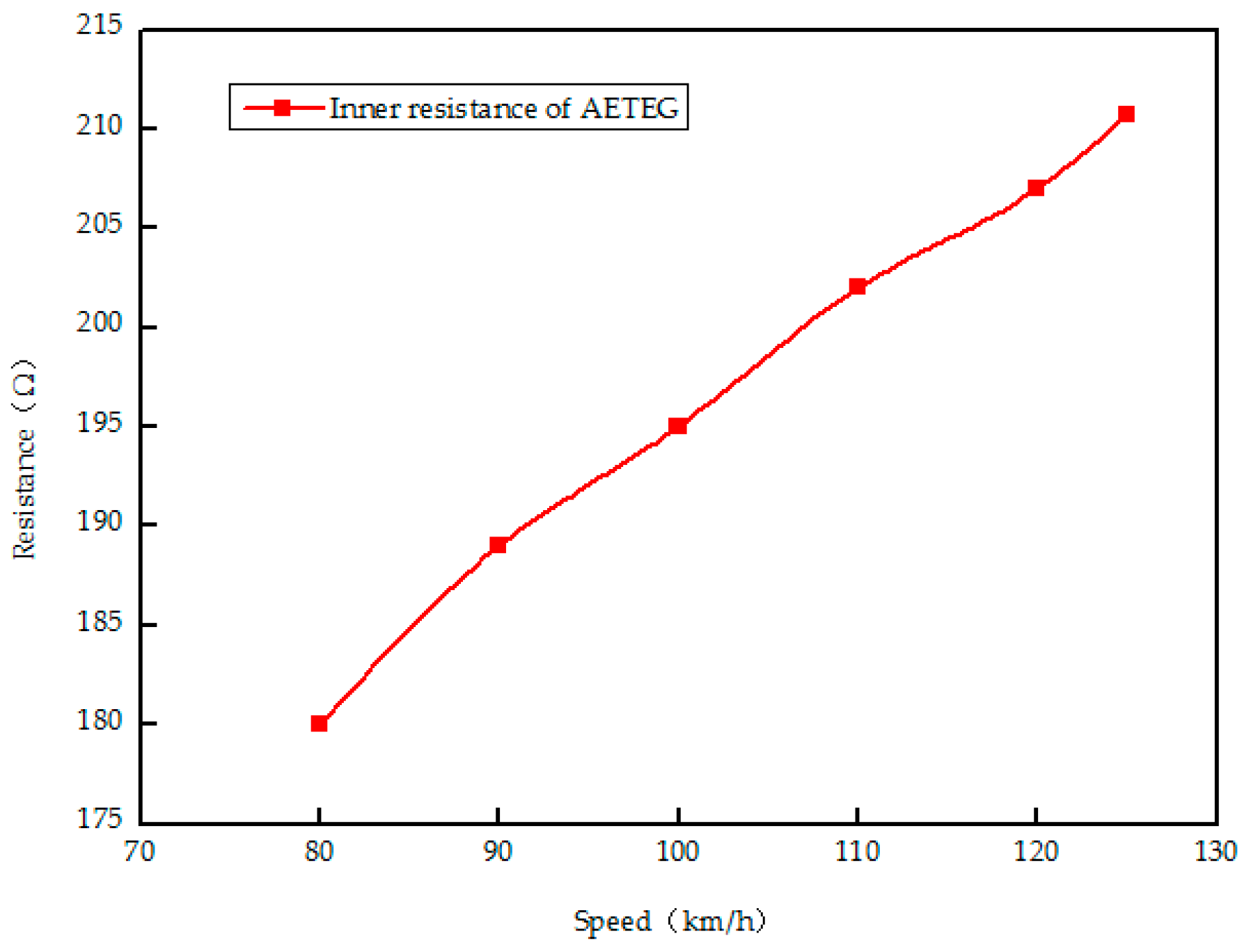
On this occasion, the inner resistance (i.e., electric resistance) of AETEG in Figure 13 increases from 180.1 Ω to 210.7 Ω when the SUV speed changes from 70 km/h to 125 km/h. For the temperature difference of AETEG is directly affected by SUV speed, it can be concluded that the inner resistance is also proportional to SUV speed (temperature difference).
In all, the output voltage, output power and the inner resistance of AETEG is in direct proportion to SUV speeds for the increased temperature difference is accompanied by the augment of SUV speeds. Thus, enlarging the temperature differences of TEMs within the highest speed limitation, such as applying the closer connection distance between heat exchangers and engine exhaust pipe, precooling inlet coolant, insulating heat radiation of uncovered areas to increase the maximum power of AETEG will be the endeavor in the next generation.
3.2. Influence of Clamping Pressure
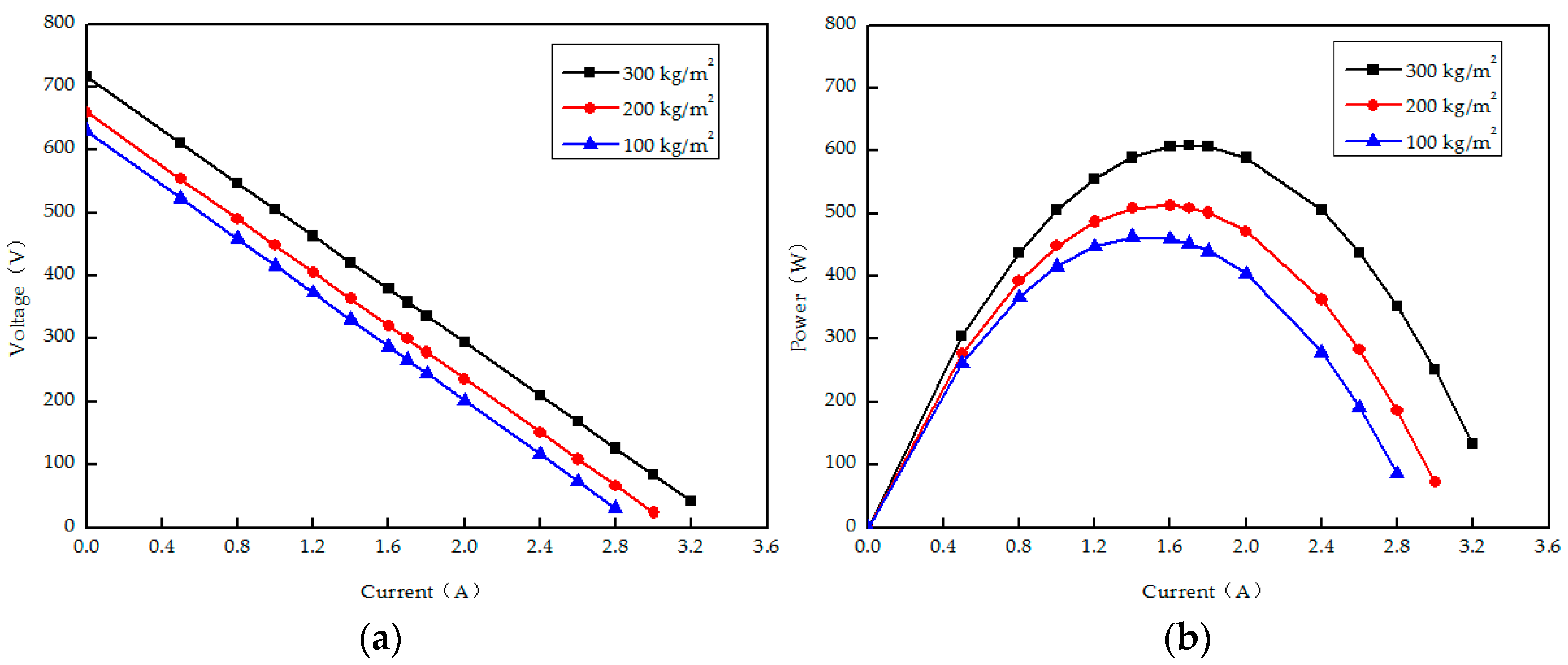
Considering the performance of TEM is influenced by its thermal contact resistance, the effect of different clamping pressures on the overall performance of AETEG is shown in Figure 14. On this occasion, the SUV operates at 125 km/h, the ambient temperature is 25 °C, and the engine coolant flow rate is 40.8 L/min. When the clamping pressure increases from 100 kg/m2 to 300 kg/m2, the maximum power sharply changes from 462.56 W to 608.85 W.
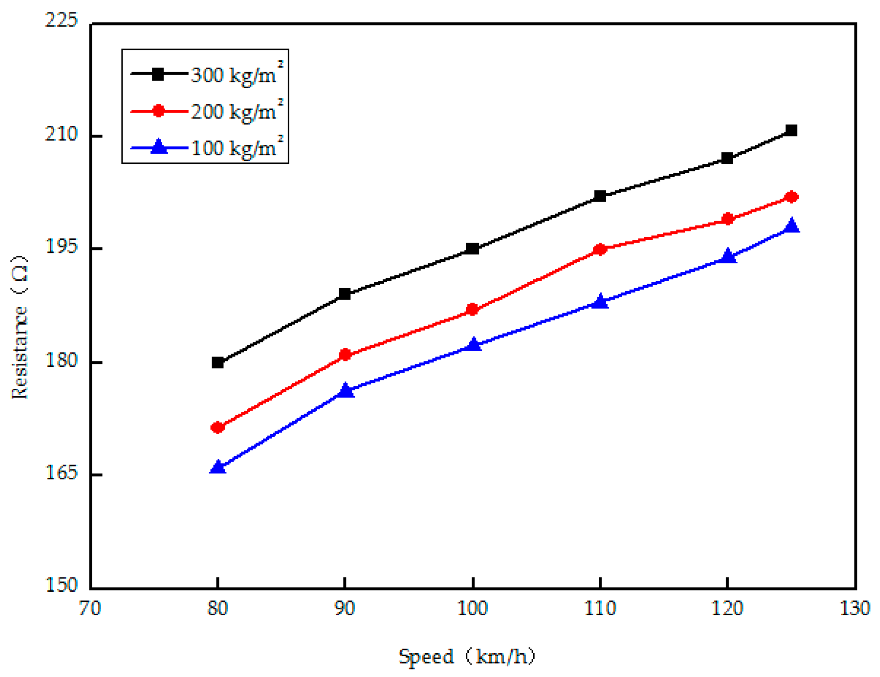
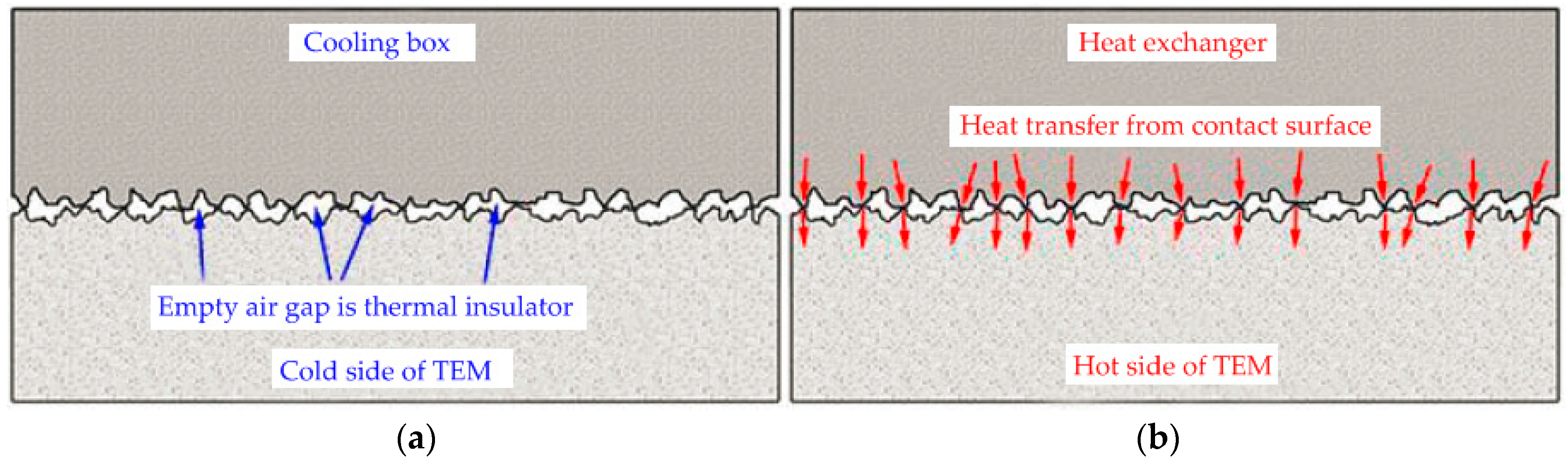
From the separate characteristics curves shown in Figure 14a, the slope of voltage versus current decreases sharply with the increased clamping pressure. Figure 15 shows the specific inner resistance of AETEG with different clamping pressures when the SUV speeds change according to the above constant ambient temperature and engine coolant flow rate. From the surface structure schematic figure of heat exchanger, a TEM and cooling box magnified by 1000 times with optical microscope shown in Figure 16, the empty air gap is an equivalent thermal insulator during the heat transfer. Combined with the presented results both in Figure 14 and Figure 15, Figure 16 demonstrates that the thermal contact resistance of AETEG can be reduced for the empty air gap among both sides of TEMs, heat exchanger and cooling boxes is narrower when the clamping pressure increases as large as possible. Thus, more of the exhaust heat can be absorbed by the hot sides of TEMs from heat exchanger, and increasing heat is brought off from the cold sides of TEMs with the rise of clamping pressure and decreasing of thermal insulator, the output performance can be enhanced accompanied with the lower inner resistance caused by larger clamping pressure. Therefore, to ensure larger output power and high efficiency, AETEG should be clamped as tight as possible within the allowable pressure of each TEM.
3.3. Influence of Engine Coolant Flow Rate
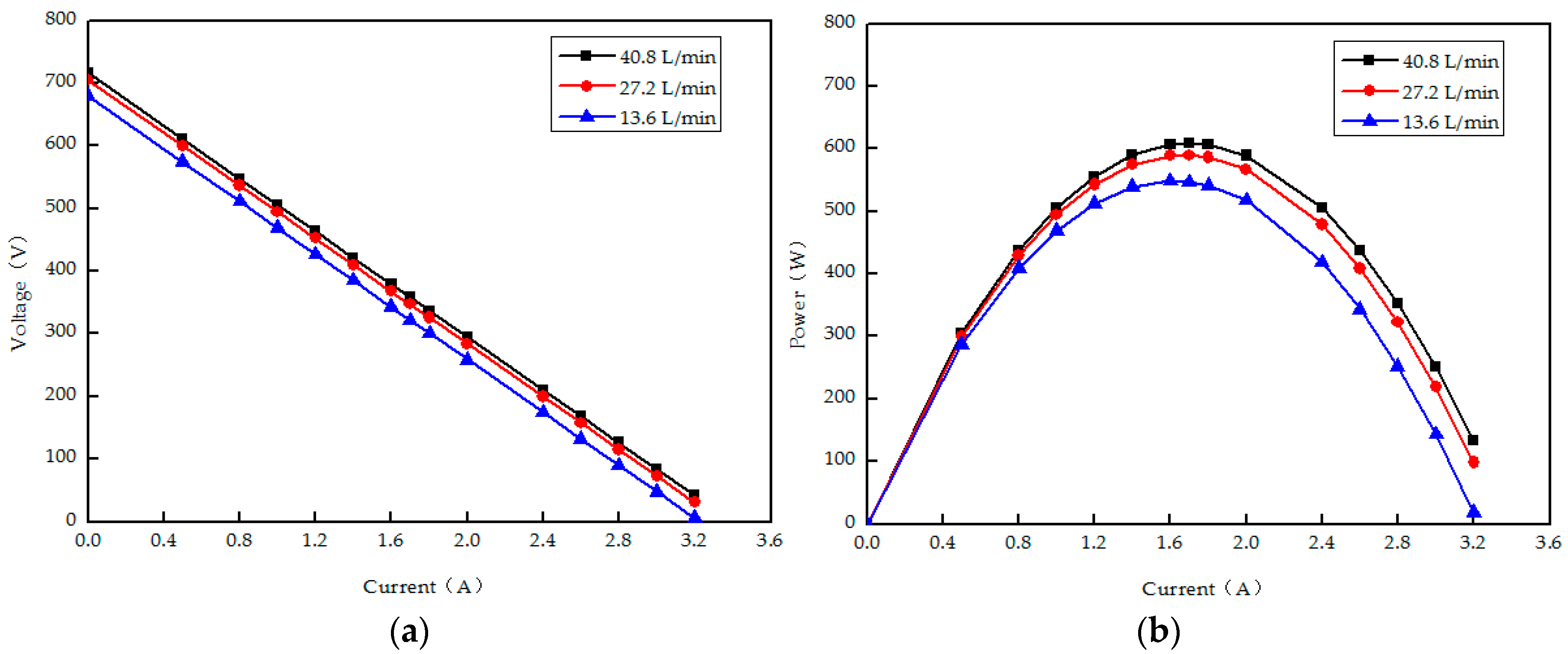
Even though the temperature of adopted engine coolant is kept around 90 °C, the cold sides temperature of TEMs is not low enough. Lacking assembly space using external cooling system can be well avoided when it is installed in vehicle. Figure 17 shows the performance characteristics of TEG with different flow rates of engine coolant adjusted by regulating valve when the SUV speed is fixed at 125 km/h, the ambient temperature is 25 °C, and the clamping pressure is 300 kg/m2. It can be seen that both the output voltage and power with the same output current (i.e., external load) increase slightly with faster flow rates, for more cold sides heat of TEMs is brought out, which leads to a relatively higher temperature difference. When the flow rate is 40.8 L/min, the maximum power is 608.85 W, which is increased by 3.4% compared with that of 27.2 L/min (588.61 W) when the corresponding flow rate increases by 100%. From the separate characteristics curves shown in Figure 17a, it can be seen that the slopes of voltage versus current are similar to the increasing clamping pressure.
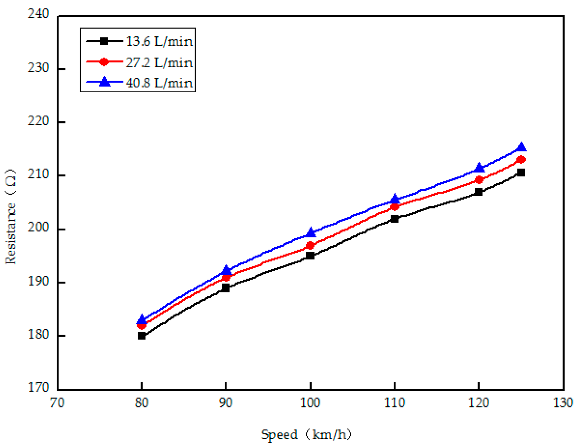
Figure 18 shows the measured inner resistance of AETEG with different engine coolant flow rates when SUV speeds change from 80 km/h to 125 km/h and the clamping pressure is 300 kg/ m2.
Larger coolant flow rate means lower cold side temperature with the same SUV speed (inlet exhaust temperature) for more heat can be brought out from the cold sides of TEMs, the inner resistance of AETEG increases with the increased engine coolant flow rate, but the difference of the inner resistant of AETEG with different coolant flow rates is very small (within 5 Ω) at the same SUV speed, the inner resistant of AETEG is mainly affected the SUV speed with the same coolant flow rate. When the flow rate is quick enough to some extent, increasing the coolant flow rate can’t obtain much higher maximum power and output voltage for the cooling capability is saturated.
3.4. Influence of Ambient Temperature
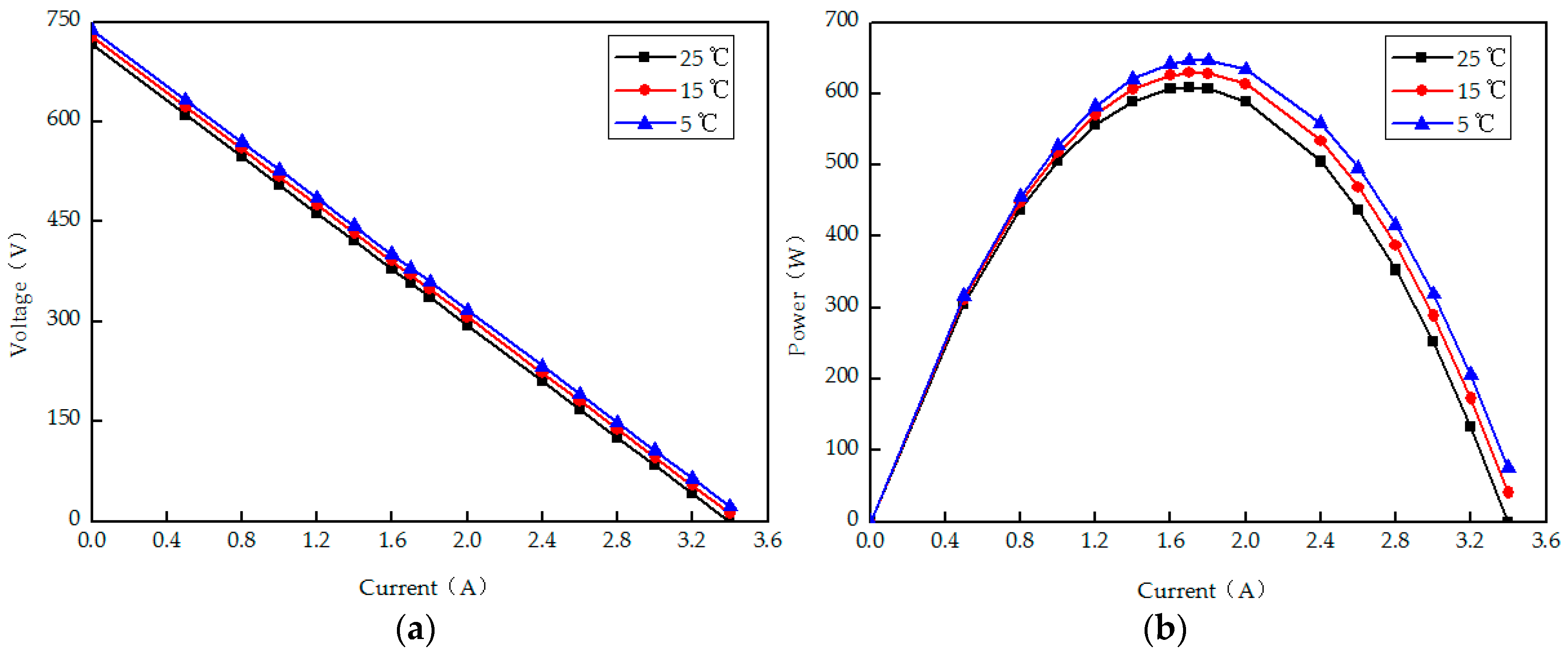
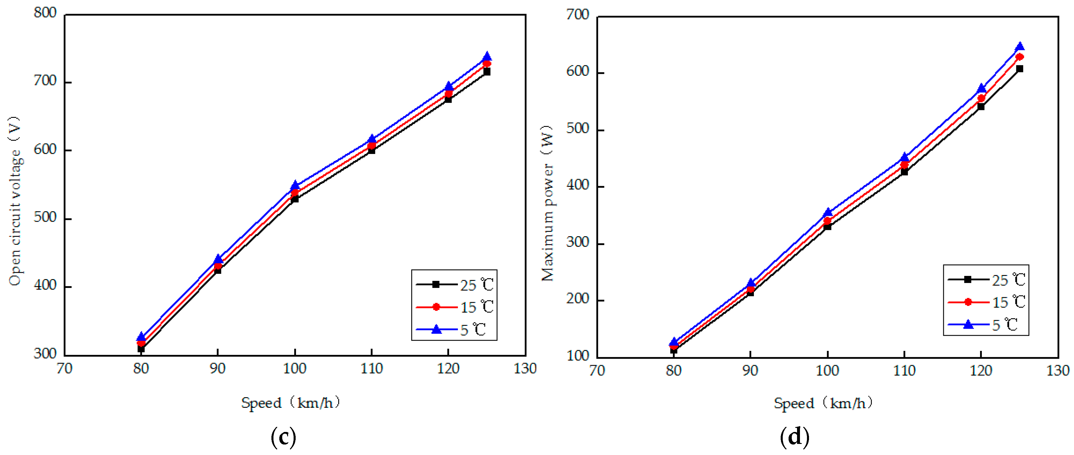
In our previous work, ambient temperature is an ignored factor that needs to be seriously considered. The ambient temperatures considered in the road test are 5 °C, 15 °C and 25 °C, which are selected at three different moments (i.e., morning, evening and noon, respectively) during a day. The performance of AETEG with different ambient temperatures is shown in Figure 19 when the maximum engine coolant flow is 40.8 L/min and the clamping pressure is 300 kg/m2.
Figure 19a,b show the voltage and output power versus current characteristics when SUV speed is maintained at 125 km/h and ambient temperature is 5 °C, 15 °C and 25 °C, respectively. Figure 19c,d show the open circuit voltage and maximum power of AETEG with different SUV speeds and the above ambient temperatures, respectively. When the ambient temperature is 5 °C, the maximum power is 646.26 W which is raised by 6.14% compared with that of 25 °C. Thus, it indicates that the overall performance of AETEG can be slightly improved with lower ambient temperature for the cooling capability of coolant is enhanced, which contributes to larger maximum power to some extent, but it is less significant compared with the above clamping pressure and engine coolant flow rate. Moreover, the effect of different ambient temperatures on the inner resistance of AETEG is ignorable for the slopes of voltage versus current are almost the same, which also validates the high reliability, stability and durability of TEMs during their service cycle within 350 °C.
3.5. System Efficiency
Except for the output voltage and power, waste heat conversion efficiency (i.e., system efficiency) is also an important index. To investigate the conversion efficiency, Saqr et al. [32] had analyzed the heat balance of TEG in detail. Apart from the effective heat transferred through TEMs, the heat losses include the heat lost from the non-used zones of heat exchanger by radiation and convection, the heat lost from the leg-sides of the TEMs by convection and radiation, the heat lost by conduction through the assembly structure, the heat lost through gaps between the TEMs, and the heat lost by conduction in the TEMs due to thermal contact resistance. At present, the input heat of heat exchanger can be easily tested, but it is difficult to precisely calculate or measure the heat losses. Considering the maximum efficiency of internal combustion engine (ICE) is about 30% and approximately 40% of the fuel energy is wasted through exhaust gas, the AETEG system efficiency η can be estimated as follows:
where PAETEG is the maximum output power of AETEG, Pengine is the engine output power of SUV. The system efficiency corresponding to the maximum output power of above AETEG with different SUV speeds and ambient temperatures is listed in Table 3. On this occasion, coolant flow rate is 40.8 L/min, and the clamping pressure is 300 kg/m2. It is can easily be seen that the system efficiency increases until the SUV speed accelerates to be 100 km/h because much more waste heat is exhausted from engine manifold and absorbed by TEMs, when the SUV speed is above 120 km/h, the waste heat absorption is saturated and the maximum system efficiency is 1.03% with different ambient temperatures. Furthermore, the compared results indicate that the system efficiency can be slightly improved with lower ambient temperature due to a little larger maximum power, but the effect of ambient temperature is less significant. For the maximum conversion efficiency of adopted Bi2Te3 TEM is 5%, the system efficiency of AETEG is acceptable, and further optimization design is still needed.
η = 3PAETEG/(4Pengine)
3.6. Backpressure
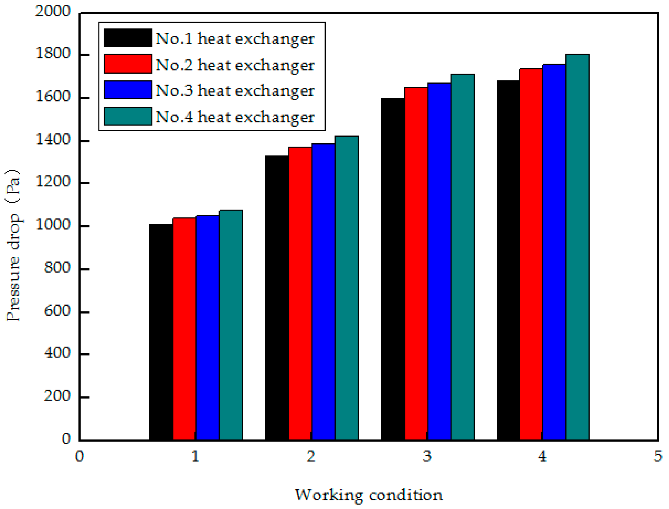
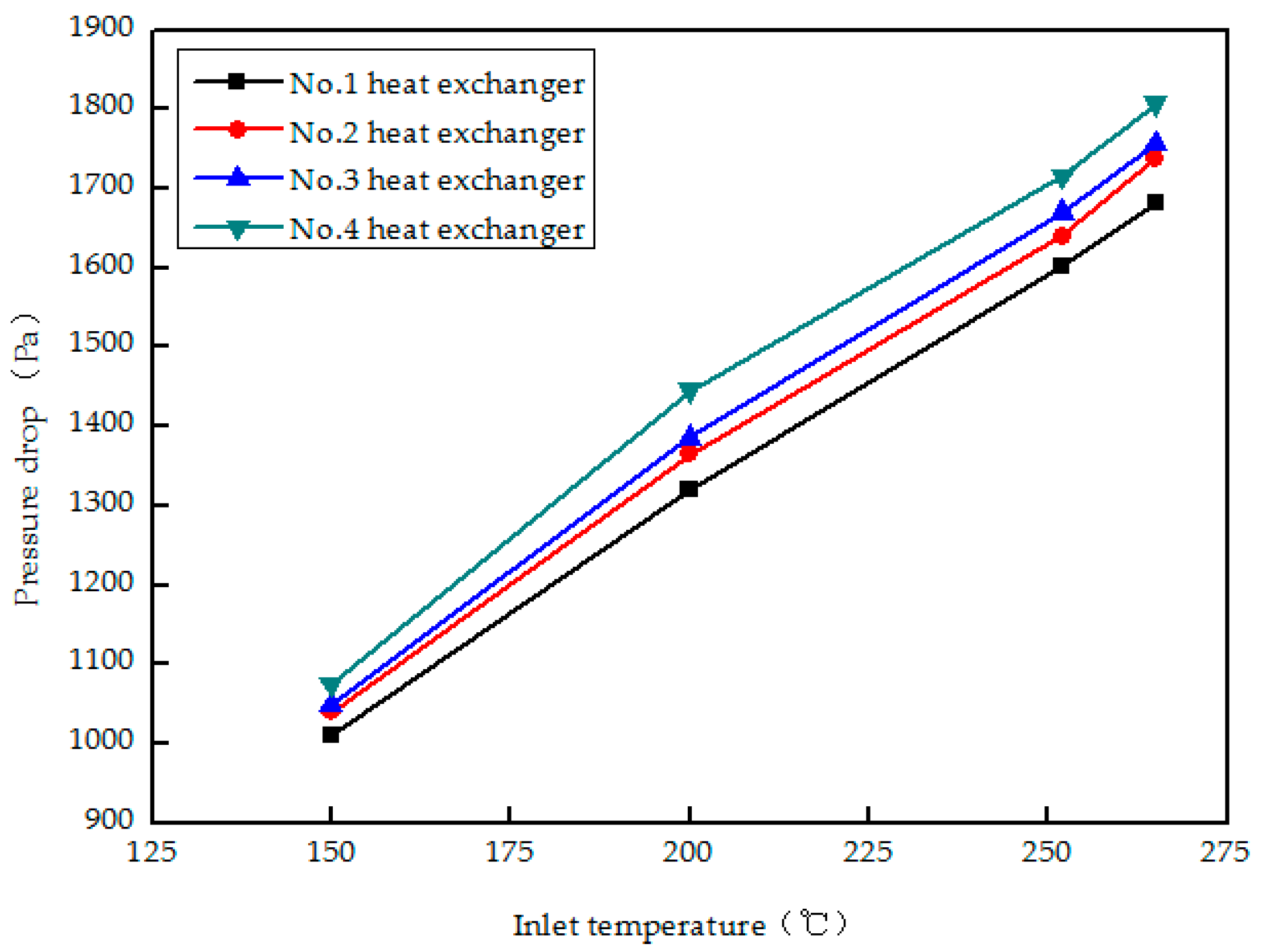
For the chaos-shaped heat exchangers presented in Figure 2, undoubtedly, the backpressure will be increased due to the AETEG as an addition to the SUV engine, the influence of the exhaust gas backpressure (or pressure drop) on the engine plays a significant role in the SUV fuel economy and emission performance. Therefore, minimizing the unwished backpressure increase by optimizing heat exchangers remains a technological challenge. To analyze the effect of four chaos-shaped heat exchangers on the backpressure of engine, the pressure drops of four heat exchangers under the four above working conditions and with their different inlet temperatures are shown are shown in Figure 20 and Figure 21, respectively.
For the inlet temperature of heat exchangers is proportional to the vehicle speed, the increased backpressure is accompanied with the augment of SUV speeds, and the pressure drops from the inlet to outlet corresponding to the four heat exchangers are similar at the same speed, the difference among them caused by the different branch structures of the manifold is within 10%. When the speed of SUV increases to 125 km/h, the maximum inlet temperature is 265 °C, the pressure drops of four heat exchangers are 1681 Pa (No. 1 heat exchanger), 1732 Pa (No. 2 heat exchanger), 1757 Pa (No. 3 heat exchanger) and 1807 Pa (No. 4 heat exchanger), respectively. Considering the back-pressure produced by the muffler usually varied from 4000 Pa to 6000 Pa, the increased exhaust flow resistance caused by the four chaos-shaped heat exchangers is acceptable and needs further reducing for it may degrade the original fuel economy and dynamic performance of ICE. Different heat exchanger of inner topologies, different pressure drops and temperature distributions, the backpressure is manageable by optimizing the fin distribution of heat exchangers with efficient exhaust heat recovering capability.
4. Conclusions
Automotive waste heat recovery based on TEMs presents a promising research focus worldwide, but enhancing AETEG performance and heat recovery efficiency without degrading the fuel economy, heat balance, and emission behavior of engine remains a significant challenge. The compound Bi2Te3 is the most common commercially available material used in TEMs to date. Despite the high ZT value of about 1.1 offered by this material, it has a very restrictive operational temperature range (usually from 20 °C to 300 °C) and relative large thermal resistance. Also, it is not technically possible to greatly enhance the TEMs performance only by increasing the ZT value of the Bi2Te3 material at present. Furthermore, the intermediate-temperature TEMs are still in progress and are not commercially available so far. In this study, a TEG system using the low-temperature Bi2Te3 TEMs to recover exhaust waste heat was designed, and the temperature distribution is analyzed. From the experimental results of temperature uniformity distribution, it can be concluded that enhancing its uniformity with the temperature optimized method of chipping peak off and filling valley can increase the maximum power to some extent even though larger engine power is needed. Based on the low-temperature Bi2Te3 TEMs and optimized TEG, a novel AETEG called “four-TEGs” system was assembled under the chassis of a prototype military SUV, the influence of several factors such as vehicle speed, clamping pressure, engine coolant flow rate and ambient temperature on its output performance is experimented and compared. The road test results on highways demonstrate that SUV speed and clamping pressure mainly influence the output voltage and power. In addition, faster coolant flow rate and lower ambient temperature can enhance its performance, but they are comparatively less significant. In addition, the inner resistance is proportional to the practical temperature differences of TEMs caused by different SUV speeds, clamping pressures, and engine coolant flow rate.
To further enhance output power and maximize system efficiency of AETEGs, there are four effective ways: raising the hot side temperature and its uniformity as much as possible by optimizing the exhaust manifold structure and heat exchanger inner topology until the SUV speed approaches the highway speed limitation; lowering the cold side temperature by precooling its inlet coolant; reducing the heat loss by covering the exposed area with thermal insulation materials; and increasing the number of TEMs. Moreover, the unwished increased backpressure caused by heat exchangers should be restricted even if the maximum power of AETEG is increased, for it will deteriorate the fuel economy and emission performance of an engine. Future work focusing on the optimization measures above is in progress and the relevant results will be reported in the next few years.
Acknowledgments
This paper has been supported by the National Natural Science Foundation of China (51407063), the International Science and Technology Cooperation Program of China (2011DFB60150), and the Doctor Scientific Research Foundation of Hubei University of Technology (BSQD13064).
Author Contributions
Guangyin Liu, Chengji Wang and Wei Zhou performed the experiments and data analysis. Rui Quan designed the experiments and wrote the manuscript. Liang Huang and Yadong Deng offered valuable discussions in analyses and revised the manuscript.
Conflicts of Interest
The authors declare no conflict of interest.
References
- Willars-Rodríguez, F.J.; Chávez-Urbiola, E.A.; Vorobiev, P.; Vorobiev, Y.V. Investigation of solar hybrid system with concentrating Fresnel lens, photovoltaic and thermoelectric generators. Int. J. Energy Res. 2017, 41, 377–388. [Google Scholar] [CrossRef]
- Demir, M.E.; Dincer, I. Performance assessment of a thermoelectric generator applied to exhaust waste heat recovery. Appl. Therm. Eng. 2017, 120, 694–707. [Google Scholar] [CrossRef]
- Li, W.K.; Peng, J.Y.; Xiao, W.L.; Wang, H.H.; Zeng, J.S.; Xie, J.; Huang, Q.B. The temperature distribution and electrical performance of fluid heat exchanger-based thermoelectric generator. Appl. Therm. Eng. 2017, 118, 742–747. [Google Scholar] [CrossRef]
- Meng, F.K.; Chen, L.G.; Feng, Y.L.; Xiong, B. Thermoelectric generator for industrial gas phase waste heat recovery. Energy 2017, 135, 83–90. [Google Scholar] [CrossRef]
- Kim, S.; Park, S.; Kim, S.K.; Rhi, S.H. A thermoelectric generator using engine coolant for light-duty internal combustion engine-powered vehicles. J. Electron. Mater. 2011, 40, 812–816. [Google Scholar] [CrossRef]
- Kim, T.Y.; Negash, A.A.; Cho, G. Waste heat recovery of a diesel engine using a thermoelectric generator equipped with customized thermoelectric modules. Energy Convers. Manag. 2016, 124, 280–286. [Google Scholar] [CrossRef]
- Bass, J.C.; Kushch, A.S.; Elsner, N.B. Thermoelectric generator development for heavy-duty truck applications. In Proceedings of the Annual Automotive Technology Development Contractors’ Coordination Meeting, Dearborn, MI, USA, 28–31 October 1991; pp. 743–748. [Google Scholar]
- Ikoma, K.; Munekiyo, M.; Furuya, K.; Kobayashi, M.; Izumi, T.; Shinohara, K. Thermoelectric module and generator for gasoline engine vehicles. In Proceedings of the 17th International Conference on Thermoelectrics-ICT1998, Nagoya, Japan, 24–28 May 1998; pp. 464–467. [Google Scholar]
- Lagrandeur, J.; Crane, D.; Mazar, S.; Eder, A. Automotive waste heat conversion to electric power using skutterudite, TAGS, PbTe and BiTe. In Proceedings of the 25th International Conference on Thermoelectrics ICT’06, Beijing, China, 6–8 August 2006; pp. 343–348. [Google Scholar]
- Thacher, E.F.; Helenbrook, B.T.; Karri, M.A.; Richter, C.J. Testing of an automobile exhaust thermoelectric generator in a light truck. J. Automob. Eng. 2007, 221, 95–107. [Google Scholar] [CrossRef]
- Hussain, Q.E.; Brigham, D.R.; Maranville, C.W. Thermoelectric exhaust heat recovery for hybrid vehicles. SAE Tech. Pap. 2009, 2, 1132–1142. [Google Scholar] [CrossRef]
- Hsu, C.T.; Huang, G.Y.; Chu, H.S.; Yu, B.; Yao, D.J. Experiments and simulations on low-temperature waste heat harvesting system by thermoelectric power generators. Appl. Energy 2011, 88, 1291–1297. [Google Scholar] [CrossRef]
- Kim, S.K.; Won, B.C.; Rhi, S.H.; Kim, S.H.; Yoo, J.H.; Jang, J.C. Thermoelectric power generation system for future hybrid vehicles using hot exhaust gas. J. Electron. Mater. 2011, 40, 778–783. [Google Scholar] [CrossRef]
- Liu, C.; Pan, X.; Zheng, X.; Yan, Y.; Li, W. An experimental study of a novel prototype for two-stage thermoelectric generator from vehicle exhaust. J. Energy Inst. 2016, 89, 271–281. [Google Scholar] [CrossRef]
- Domingues, A.; Santos, H.; Costa, M. Analysis of vehicle exhaust waste heat recovery potential using a Rankine cycle. Energy 2013, 49, 71–85. [Google Scholar] [CrossRef]
- Kumar, S.; Heister, S.D.; Xu, X.F.; Salvador, J.R.; Meisner, G.P. Thermoelectric generators for automotive waste heat recovery systems part II: Parametric evaluation and topological studies. J. Electron. Mater. 2013, 42, 944–955. [Google Scholar] [CrossRef]
- Kuhn, R.; Koeppen, O.; Kitte, J. Influence of an optimized thermoelectric generator on the back pressure of the subsequent exhaust gas system of a vehicle. J. Electron. Mater. 2014, 43, 1521–1526. [Google Scholar] [CrossRef]
- Martinez, A.; Vian, J.G.; Astrain, D.; Rodriguez, A.; Berrio, I. Optimization of the heat exchangers of a thermoelectric generation system. J. Electron. Mater. 2010, 39, 1463–1468. [Google Scholar] [CrossRef]
- Kempf, N.; Zhang, Y.L. Design and optimization of automotive thermoelectric generators for maximum fuel efficiency improvement. Energy Convers. Manag. 2016, 121, 224–231. [Google Scholar] [CrossRef]
- Bi, C.; Tang, G.H.; Tao, W.Q. Heat transfer enhancement in mini-channel heat sinks with dimples and cylindrical grooves. Appl. Therm. Eng. 2013, 55, 121–132. [Google Scholar] [CrossRef]
- David, B.; Ramousse, J.; Luo, L. Optimization of thermoelectric heat pumps by operating condition management and heat exchanger design. Energy Convers. Manag. 2012, 60, 125–133. [Google Scholar] [CrossRef]
- Wang, C.C.; Hung, C.I.; Chen, W.H. Design of heat sink for improving the performance of thermoelectric generator using two-stage optimization. Energy 2012, 39, 236–245. [Google Scholar] [CrossRef]
- Kubo, M.; Shinoda, M.; Furuhata, T.; Kitagawa, K. Optimization of the incision size and cold-end temperature of a thermoelectric device. Energy 2005, 30, 2156–2170. [Google Scholar] [CrossRef]
- Yilbas, B.S.; Sahin, A.Z. Thermoelectric device and optimum external load parameter and slenderness ratio. Energy 2010, 35, 5380–5384. [Google Scholar] [CrossRef]
- Jang, B.; Han, S.; Kim, J.Y. Optimal design for micro-thermoelectric generators using Finite element analysis. Microelectron. Eng. 2011, 88, 775–778. [Google Scholar] [CrossRef]
- Su, C.Q.; Zhan, W.W.; Shen, S. Thermal optimization of the heat exchanger in the vehicular waste-heat thermoelectric generations. J. Electron. Mater. 2012, 41, 1693–1697. [Google Scholar] [CrossRef]
- Liu, X.; Deng, Y.D.; Zhang, K.; Xu, M.; Xu, Y.; Su, C.Q. Experiments and simulations on heat exchangers in thermoelectric generator for automotive application. Appl. Therm. Eng. 2014, 71, 364–370. [Google Scholar] [CrossRef]
- Wang, Y.P.; Cheng, W.; Tang, Z.B.; Xue, Y.; Deng, Y.D.; Su, C.Q. Optimization of fin distribution to improve the temperature uniformity of a heat exchanger in a thermoelectric generator. J. Electron. Mater. 2015, 44, 1724–1732. [Google Scholar] [CrossRef]
- Wang, Y.P.; Li, S.; Xue, Y.; Deng, Y.D.; Su, C.Q. Numerical and experimental investigation for heat transfer enhancement by dimpled surface heat exchanger in thermoelectric generator. J. Electron. Mater. 2016, 45, 1792–1802. [Google Scholar] [CrossRef]
- Gou, X.; Xiao, H.; Yang, S. Modeling, experimental study and optimization on low-temperature waste heat thermoelectric generator system. Appl. Energy 2010, 87, 3131–3136. [Google Scholar] [CrossRef]
- Quan, R.; Zhou, W.; Yang, G.Y.; Quan, S.H. A hybrid maximum power point tracking method for automobile exhaust thermoelectric generator. J. Electron. Mater. 2017, 46, 2676–2683. [Google Scholar] [CrossRef]
- Saqr, K.M.; Mansour, M.K.; Musa, M.N. Thermal design of automobile exhaust based thermoelectric generator: Objectives and challenges. Int. J. Automot. Technol. 2008, 9, 155–160. [Google Scholar] [CrossRef]
Figure 1.
Schematic of an experimental setup of a thermoelectric generator (TEG) system.

Figure 2.
TEG architecture.

Figure 3.
The temperature distribution of heat exchanger with different engine revolution rates.

Figure 4.
The inlet and outlet temperature of heat exchanger with different engine revolution rates.
Figure 4.
The inlet and outlet temperature of heat exchanger with different engine revolution rates.

Figure 5.
Maximum output power of TEMs with (a) horizontal rows, and (b) vertical rows.

Figure 6.
Optimization of temperature uniformity.

Figure 7.
Comparisons of surface temperature distribution (maximum temperature is 337 °C).

Figure 8.
Maximum output power comparison TEMs with (a) vertical rows, and (b) horizontal rows.

Figure 9.
Road test object map of automobile exhaust thermoelectric generator (AETEG) used in prototype sports utility vehicle (SUV).
Figure 9.
Road test object map of automobile exhaust thermoelectric generator (AETEG) used in prototype sports utility vehicle (SUV).

Figure 10.
Characteristics curves of different SUV speeds with (a) voltage versus current and (b) and power versus current.
Figure 10.
Characteristics curves of different SUV speeds with (a) voltage versus current and (b) and power versus current.

Figure 11.
Temperature distribution of AETEG with different SUV speeds with (a) hot side temperatures and (b) cold side temperatures.
Figure 11.
Temperature distribution of AETEG with different SUV speeds with (a) hot side temperatures and (b) cold side temperatures.

Figure 12.
The maximum and minimum temperature difference with different SUV speeds.

Figure 13.
The inner resistance of AETEG with different SUV speeds.

Figure 14.
AETEG performance with clamping pressure of 100 kg/m2, 200 kg/m2 and 300 kg/m2. (a) voltage versus current curves, (b) power versus current curves.
Figure 14.
AETEG performance with clamping pressure of 100 kg/m2, 200 kg/m2 and 300 kg/m2. (a) voltage versus current curves, (b) power versus current curves.

Figure 15.
AETEG inner resistance with different clamping pressures and SUV speeds.

Figure 16.
Schematic figure of surface magnified by 1000 times. (a) Cold side of TEM and cooling box; (b) Hot side of TEM and heat exchanger.
Figure 16.
Schematic figure of surface magnified by 1000 times. (a) Cold side of TEM and cooling box; (b) Hot side of TEM and heat exchanger.

Figure 17.
Characteristics curves of voltage-current-power with different coolant flow rates.

Figure 18.
Resistance of AETEG with different coolant flow rates and SUV speeds.

Figure 19.
AETEG output performance with ambient temperatures of 5 °C, 15 °C and 25 °C. (a) voltage versus current curves; (b) power versus current curves; (c) open circuit voltage versus SUV speed curves; (d) maximum power versus SUV speed curves.
Figure 19.
AETEG output performance with ambient temperatures of 5 °C, 15 °C and 25 °C. (a) voltage versus current curves; (b) power versus current curves; (c) open circuit voltage versus SUV speed curves; (d) maximum power versus SUV speed curves.


Figure 20.
Backpressure of AETEG with different working conditions.

Figure 21.
Backpressure of AETEG with different inlet temperatures.


Table 1.
Parameters of experimental setup of a TEG system.
| Parameter | Value |
|---|---|
| Dimension of TEM | 56 mm × 56 mm × 6 mm |
| Materials of TEM | Bi2Te3 |
| Maximum operating temperature of TEM | 350 °C |
| Maximum conversion efficiency of TEM | 5% |
| Capacity of engine | 2.0 L (PSA RFN 10LH3X) |
| Maximum power of engine | 108 kW (6000 r/min) |
| Maximum torque of engine | 200 NM (4000 r/min) |
| Maximum power of dynamometer | 160 kW |
| Maximum speed of dynamometer | 6000 r/min |
| Maximum torque of dynamometer | 600 NM |
| Dimension of cooling box | 300 mm × 60 mm × 21 mm |
| Materials of cooling box | Aluminum |
| Materials of heat exchanger | Brass |
| Materials of clamping devices | Steel |
| Thickness of heat exchanger | 5 mm |
| Thickness of cooling box | 3 mm |
| Maximum power of pump | 750 W (220 VAC) |
| Rated power of radiator | 200 W (12 VDC) |
Table 2.
Parameters of SUV for AETEG.
| Parameter | Value |
|---|---|
| Dimension | 4717 mm × 2210 mm × 19,835 mm |
| Frontal area | 5.17 m2 |
| Total weight | 3500 kg |
| Rolling resistance coefficient | 0.0135 |
| Wind resistance coefficient | 0.65 |
| Wheel radius | 0.37 m |
| Capacity of engine | 3.9 L (EQB150-20) |
| Type of engine | Four-cylinder diesel |
| Rated power of engine | 112 kW (2700 r/min) |
| Maximum torque of engine | 502 NM (1500 r/min) |
| Maximum revolution rate of engine | 3000 r/min |
Table 3.
System efficiency of AETEG.
| Ambient Temperature | Efficiency | |||
|---|---|---|---|---|
| 80 km/h | 100 km/h | 120 km/h | 125 km/h | |
| 5 °C | −0.49% | 0.92% | 1.02% | 1.03% |
| 15 °C | −0.47% | −0.90% | 0.99% | 1.00% |
| 25 °C | 0.45% | −0.86% | 0.96% | 0.97% |
© 2018 by the authors. Licensee MDPI, Basel, Switzerland. This article is an open access article distributed under the terms and conditions of the Creative Commons Attribution (CC BY) license (http://creativecommons.org/licenses/by/4.0/).
Share and Cite
MDPI and ACS Style
Quan, R.; Liu, G.; Wang, C.; Zhou, W.; Huang, L.; Deng, Y. Performance Investigation of an Exhaust Thermoelectric Generator for Military SUV Application. Coatings 2018, 8, 45. https://0-doi-org.brum.beds.ac.uk/10.3390/coatings8010045
AMA Style
Quan R, Liu G, Wang C, Zhou W, Huang L, Deng Y. Performance Investigation of an Exhaust Thermoelectric Generator for Military SUV Application. Coatings. 2018; 8(1):45. https://0-doi-org.brum.beds.ac.uk/10.3390/coatings8010045
Chicago/Turabian StyleQuan, Rui, Guangyin Liu, Chengji Wang, Wei Zhou, Liang Huang, and Yadong Deng. 2018. "Performance Investigation of an Exhaust Thermoelectric Generator for Military SUV Application" Coatings 8, no. 1: 45. https://0-doi-org.brum.beds.ac.uk/10.3390/coatings8010045
Note that from the first issue of 2016, this journal uses article numbers instead of page numbers. See further details here.