Article

Effect of Incorporating MoS2 in Organic Coatings on the Corrosion Resistance of 316L Stainless Steel in a 3.5% NaCl Solution

1
School of Advanced Material Science and Engineering, Sungkyunkwan University (SKKU), Suwon 16419, Korea
2
School of Mechanical Engineering, Sungkyunkwan University (SKKU), Suwon 16419, Korea
*
Authors to whom correspondence should be addressed.
These authors contributed equally to this study.
Submission received: 11 December 2018 / Revised: 11 January 2019 / Accepted: 11 January 2019 / Published: 15 January 2019

Abstract

:
This study discusses a new coating method to protect 316L stainless steel (SS) from pitting corrosion in high chloride environments. The SS surface was coated using a simple, eco-friendly method, and sunflower oil (SunFO) was used as a base coating and binder for molybdenum disulfide (MoS2). The coated surface was observed using scanning electron microscopy (SEM) with an energy dispersive spectrometer (EDS) and X-ray diffraction (XRD). Corrosion behavior was examined by open-circuit potential (OCP) measurement and electrochemical impedance spectroscopy (EIS) in an 3.5% NaCl solution. The SunFO coating with MoS2 showed the highest corrosion resistance and coating durability during the immersion time relative to the SunFO coating and bare 316L SS. The increased corrosion resistance is thought to be because of the interactions with the aggregations of the SunFO lamellar structure and MoS2 in the coating film, which acted as a high order layer barrier providing protection from the metals to electrolytes.

1. Introduction

Austenitic stainless steel (SS) has excellent corrosion resistance in various environments, so they are used as materials in multiple applications such as pipelines, pumps, and structural steels in many industries [1]. Among them, 316L SS has good mechanical and welding properties with high corrosion resistance; therefore, it is regarded as one of the most effective materials in the field of corrosion [2,3]. The high corrosion resistance of 316L SS comes from a thin chromium oxide film which has high stability against corrosion [4]. In marine atmospheric environments, however, it often suffers from pitting-type corrosion due to exposure to stagnant seawater and through the deposition of airborne sea salts, which have high humidity and high chloride concentration [5]. When pitting corrosion is initiated, the pit propagates aggressively because the pH within the pit inside turns acidic due to the generation of CrCl3, which is called the autocatalytic mechanism [6]. Moreover, the pitting corrosion of SS could cause stress corrosion cracking (SCC) which results in unpredictable, brittle fracture [7]. For these reasons, corrosion protection of stainless steel in high chloride environments is a major concern in many industries. As such, several corrosion mitigation methods are being studied and developed in various fields.
Alkyd coatings are extensively used for the surface coatings as binders and adhesives. This class of coating is generated from polyols, dibasic and fatty acids or oils by condensation polymerization [8]. Alkyds have attracted significant attention among coating materials because they are lower cost and incur fewer film defects during applications. Recently, vegetable oils have been highlighted as a new effective organic coating that are nontoxic, nondepletable, domestically abundant, nonvolatile and a biodegradable resource [9]. The vegetable oils are triacylglycerols of fatty acids with high degrees of unsaturated sites which can have the ability to polymerize via cross-linking under certain conditions [10]. Polar molecules present in the oils can be absorbed on metal surfaces and form the corresponding metal oxides, which will enhance the stability of passivation and promote adhesion [9]. Sunflower oil (SunFO) coating is reported to be an effective inhibitor of corrosion for carbon steel, which is likely due to the lamellar-like layered structures of the organic film [9,11]. However, there are few studies surrounding the corrosion inhibition mechanism of the SunFO coating for SS and methods for synthesizing the SunFO coating using other effective materials. Therefore, in this study, the sunflower oil is selected as a base coating and binder for 316L SS.
The two-dimensional (2D) materials have been extensively researched within the context of several applications as coating materials because of their interesting, atomically thin, physical, chemical and electrical properties [12,13]. Among 2D materials, molybdenum disulfide (MoS2) has been widely applied as a lubrication and thin film protection coating materials because of its tribological and corrosion resistance properties [14,15]. Moreover, MoS2 remains stable in various solvents and oxygenated environments, and it can also withstand high temperatures and pressures [16,17]. Currently, however, many surface modifications, such as chemical vapor deposition (CVD), water transfer are being phased out due to their high cost, lengthy processing time, low output and harmful effects on environments. This has motivated current research, which is being conducted to improve the stability and corrosion resistance with a mixture consisting of MoS2 particles and several organic coating materials without imparting the toxic effects [18].
This study discusses a new coating method to protect 316L SS from the pitting corrosion when exposed to a 3.5% NaCl solution. Scanning electron microscopy (SEM) with energy dispersive spectrometry (EDS) was used to observe the dispersion of MoS2 on the SS surface and cross section. In addition, X-ray diffraction (XRD) measurements were performed to evaluate the coating materials on SS. After that, the electrochemical properties of organic coatings according to MoS2 were evaluated by using open-circuit potential (OCP) measurement and electrochemical impedance spectroscopy (EIS) tests.

2. Materials and Methods

2.1. Specimens and Solution Preparation

The chemical composition of the 316L SS is given in Table 1. For the electrochemical tests and the coating procedure, the surface of the specimen was polished with 2000-grit silicon carbide (SiC) paper, rinsed with ethanol and then dried with N2 gas.
Figure 1 shows a schematic diagram of the experimental procedures and expected coating structure. A 1 mg amount of MoS2 particles (commercially purchased, Sigma-Aldrich, St. Louis, MI, USA) was mixed with 10 mL of sunflower oil (commercially purchased) in 20 mL beakers. The mixture was sonicated and then stirred at 1000 rpm at room temperature for 3 h. Then, 100 μL of the mixture was dropped on the SS substrate and heated at 275 °C for 10 min on a hot plate and slowly cooled. At this temperature, the triglycerides which is a main composition of sunflower oil undergo polymerization through oxidation [10]. The SunFO with MoS2 coatings were presumed to have a layered oil structure which contained evenly distributed MoS2 particles.
To observe the cross section of the coated specimens, the cross section was polished with 2000-grit silicon carbide (SiC) paper. All electrochemical experiments were conducted in a 3.5% NaCl solution at ambient temperature.

2.2. Surface Analysis

The surface morphology and the cross-sectional image of the specimens were observed using SEM/EDS (JSM-7600F, Jeol Ltd., Tokyo, Japan) to verify the dispersion of MoS2 in organic coating. X-ray diffraction (XRD, D8 Advance, Bruker Co., Karlsruhe, Germany) measurements were performed on the specimens to identify the effective bonding within the organic coating, MoS2 and 316L SS. The XRD analysis of the coated specimens was conducted to confirm the crystalline properties of the coating film using Cu Kα radiation (λ = 1.54178 Å) in the 2θ range 0–60° at a scan rate of 0.017° 2θ.

2.3. Electrochemical Investigation Method

All electrochemical experiments were performed using a three-electrode system in a 1000 mL Pyrex glass corrosion cells connected to an electrochemical apparatus (VSP 300, Bio-Logic SAS, Seyssinet-Pariset, France). The test specimens were connected to a working electrode, graphite rods were used as the counter electrode and a saturated calomel electrode (SCE) was used as the reference electrode. The exposed area of the test specimen to the electrolyte was 0.25 cm2 (0.5 cm × 0.5 cm). An initial open-circuit potential (OCP) was established within 3 h to carry out the entire electrochemical test. The electrochemical impedance spectroscopy (EIS, VSP 300, Bio-Logic SAS, Seyssinet-Pariset, France) was carried out with an amplitude of 20 mV in a frequency range from 100 kHz to 10 mHz. The EIS tests were performed at 3, 12, 36 and 63 h to investigate variations of the coating durability in corrosive media. The impedance plots were interpreted on the basis of equivalent circuits using a suitable fitting procedure through the ZSimpWin software (ZsimpWin 3.20).

3. Results

3.1. Surface Analysis

The SEM/EDS analysis is used to probe the morphologies of the SunFO coated SS. The addition of the pristine MoS2 in the SunFO significantly impacted the surface morphology. As shown in Figure 2, the SunFO with the MoS2 coating film shows the presence of a large number of MoS2 flakes which averaged an even layer 1–3 µm thick on the entire surface (Figure 2a–d). The EDS data indicated that the surface consisted of Mo, S, Cr, Ni, and Fe corresponding to particles of MoS2 and the surface of the SS (Figure 2e).
Figure 3 shows cross-sectional images of SunFO with the MoS2 coating specimen. The thickness of the coating was verified at about 3–4 µm and shows uniform and dense surface features. According to the EDS mapping results (Figure 3b,c), it was revealed that the MoS2 particle existed in the SunFO coating layer. However, it was difficult to observe the layered structure of the oil, so the SEM analysis was re-conducted on an unpolished condition. In Figure 4, a layered structure was observed, and it was demonstrated that the coating structure of the specimen corresponded to the expectation outlined in Figure 1.
The XRD patterns in Figure 5 show the crystalline nature of the MoS2 and substrate. In previous reports, the diffraction pattern of bulk MoS2 has strong and sharp peaks which correspond to (100), (002), (100), (103), (105), and (110) planes [19]. After SunFO with MoS2 coating, the MoS2 peaks were only detected via the (002) peak corresponding to the angle of 15° because the MoS2 was oriented to a layered structure on the SS. The additional diffraction peaks at 44.5° and 19.6° indicate crystalline iron in the SS substrate and SunFO.

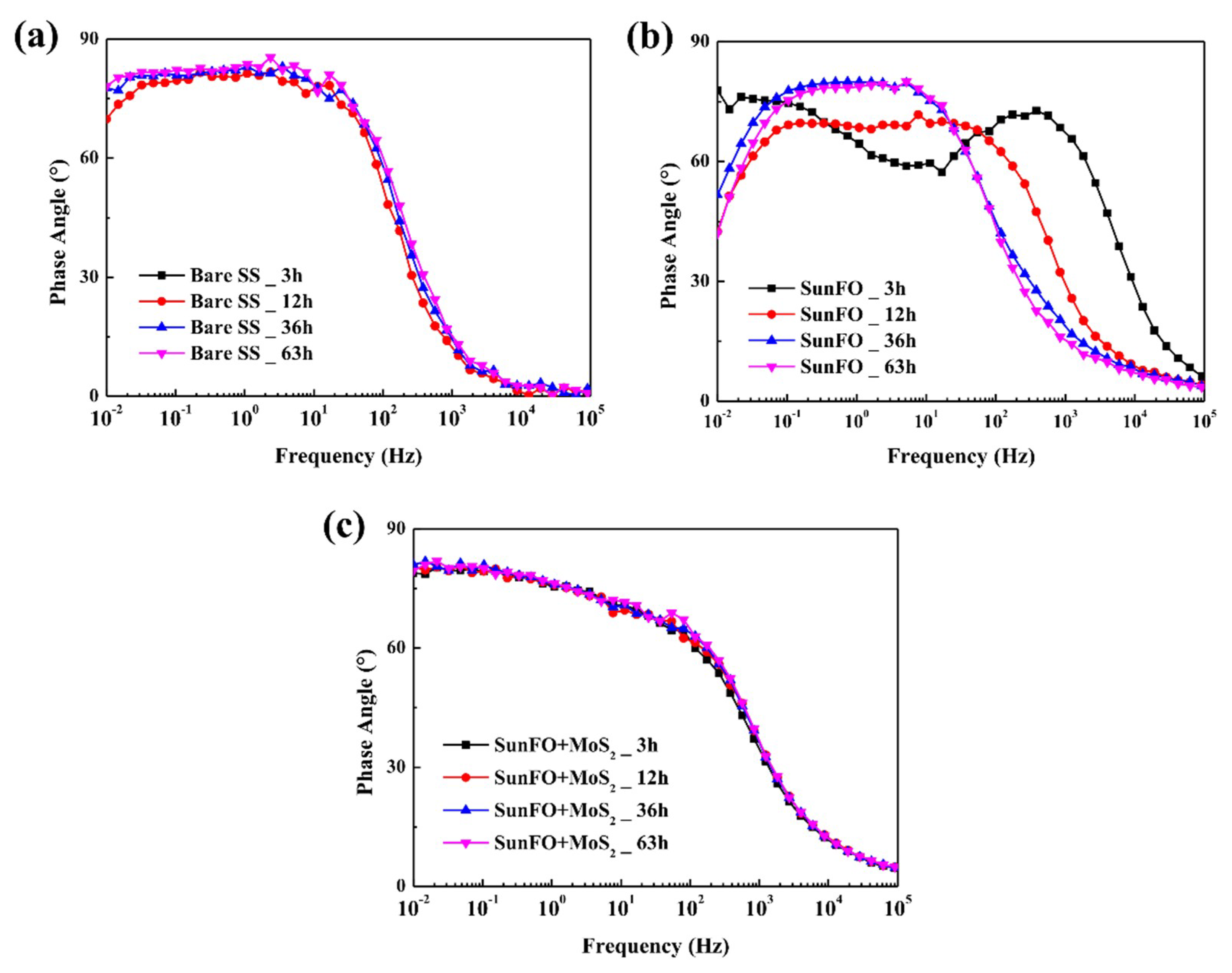
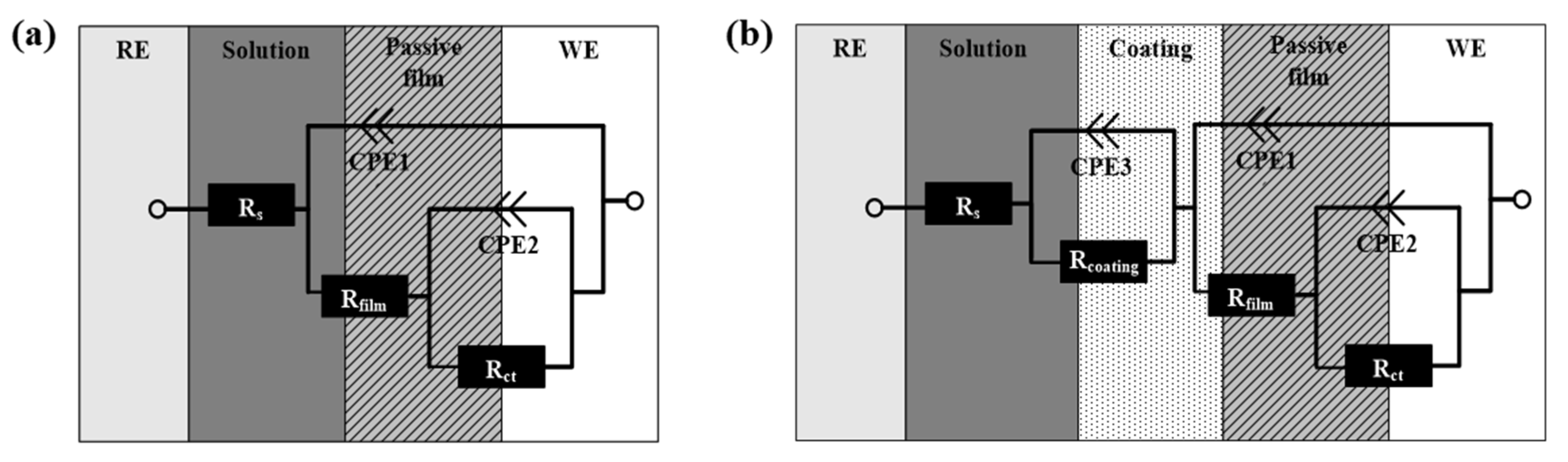
3.2. Electrochemical Analysis (EIS Tests)

The impedance spectra were obtained in the form of Nyquist plots of the data from the three-electrode system as shown in Figure 6. The tests were conducted with the following specimens, bare, SunFO coating and SunFO with a MoS2 coating at room temperature. The specimens were tested in a 3.5% NaCl solution for a total of 63 h. The Nyquist plot consisted of a depressed capacitive loop at high frequency values [20,21]. As shown in Figure 6a, the capacitive loop of bare SS increased as time progresses, because the passive film on the surface goes to stable in the solution [22,23,24]. While, in case of the SunFO coated SS, the loops decreased with immersion time, which was caused by a deterioration of oil coating (Figure 6b) [25,26]. The capacitive loop of SunFO coating with MoS2 on SS had little change during the test period, so it was regarded as a non-time-dependent effect in the solution as shown in Figure 6c.
In Figure 7a, the capacitive loop of bare SS was the smallest initially, however it displayed a reversed trend compared with the plot of the SunFO coated SS at the final time (Figure 7b). The SunFO coating with MoS2 on the surface maintained the loop tendency during the entire immersion time. It can be also verified in the OCP graph seen in Figure 8. The SunFO with MoS2 coating SS revealed very stable potential, which obviously differed from the bare and SunFO coated SS. Moreover, the potential of SunFO coated SS continuously decreased and reversed compared with the potential of bare specimen after about 28 h, which was the same tendency observed in the time-dependent variation of the Nyquist plot.
Figure 9 presents the EIS results in the form of Bode phase plots during immersion for 63 h. The Bode phase plot provided more clear description of the electrochemical frequency-dependent behavior than did the Nyquist plot, where the frequency values are implicit [27]. The high frequency spectra detects local surface defects, whereas the low frequency spectra detects the processes within the film and at the metal/film interface, respectively [28,29]. As shown in Figure 9a, in case of the bare SS, the phase angle maximum is slightly increased, and the width of the graph is wider in the low frequency region according to the test time. It means the passive film on the surface goes to more uniform and thicker [30,31,32,33]. In the case of SunFO coated SS, there was evidence of variations in surface conditions (Figure 9b). The initial stage of the specimen had two-time constants, but it changed to one-time constant at the final stage [34]. In addition, the Bode plot of SunFO coated SS has a low phase angle maximum and narrow shoulder width. This indicated that the SunFO coating had a poor protective property and has many defects [35,36,37,38]. The specimen coated with SunFO and MoS2 did not exhibit strong time-dependent behavior in the graphs, however it had a very wide frequency area as shown in Figure 9c. This is thought to be due the maintenance of a thick and uniform film throughout the entire test period.
Figure 10a shows the equivalent electrical circuits for bare SS, which had a passive film, and was used to analyze the results of the EIS tests (one-time constant circuit) [27]. In this figure, Rs is the solution resistance, CPE1 is the dielectric strength of the film and water absorbed by the film, and Rfilm is the electrical resistance resulting from the formation of an ionic conduction path through the pores in the film. The capacitance generated by the metal dissolution reaction and by the electric double layer at the electrolyte/substrate interface is designated by CPE2, and Rct is the resistance caused by the metal dissolution reaction. In the case of SunFO coated specimens, however, more circuit parameters should be added because the oil coating generates a new layer which forms a two-layered film (two-time constant circuit) [39]. As shown in Figure 10b, Rcoating is the SunFO coating resistance and CPE3 is the dielectric strength of the SunFO coating. The ZSimpWin program of the defined equivalent circuits was used to fit the EIS data to determine the optimized values for the resistance parameters, which are presented in Table 2. The Rfilm and Rct of bare SS increased according to the immersion time. These values indicated an increase of the passive film’s stability, which was the same tendency identified in the Nyquist and Bode plot. The film and coating capacitance (Cfilm, Ccoating) is described by the expression [20,40]:
C = ε A d
where A is the surface area of specimen, ε is the dielectric constant, and d is thickness of the passive film in solution. This equation suggests that a decrease of C d l is related to an increase of passive film’s thickness. The Cfilm of bare SS decreased with time, therefore this indicated that the passive film on the surface becomes thicker at final stage. In the case of the SunFO coated specimen, there were too many error values when it was applied to a two-time constant circuit after the initial stage. As shown in the Bode plot, two-time constants were displayed only at the initial stage and one-time constant was shown after that. In other words, the SunFO coating on the SS surface became degraded prior to 12 h. For this reason, the simulation was conducted to the point of one-time constant after the initial stage. According to the data shown in Table 2, Rfilm and Rct decreased according to immersion time, which meant the film had deteriorated. Especially, the Rfilm and Cfilm rapidly decreased after 36 h which indicates that a thick and porous non-protective layer was generated on the surface [41,42,43]. The SunFO with MoS2 coated SS showed an obvious two-time constant, which fit well with the two-time circuit. Both values, Rcoating and Rct, increased according to the test period, and the Rcoating value at 63 h was markedly greater than the Rfilm of bare SS at the same time, which indicated excellent protective film properties. Moreover, the Rfilm value remained very small relative to that of bare SS. It is presumed that the SunFO coating with the MoS2 blocks the electrolyte and oxygen so that the passive film could not form.
The SunFO is a complex mixture of triacylglycerol consisting of tri-esters of glycerol and fatty acid [44,45]. At high temperature, the unsaturated fatty acid of SunFO undergoes oxidation reactions and cross links with the SS. According to the XRD results (Figure 5), the SunFO layer has crystalline peaks at 19.6° which means the liquid states of the fat were crystallized on the SS. According to the expected coating structure (Figure 1), the SunFO coating, which has fatty acid hydrocarbon chains, makes lamellar structures as identified by the subcell concept [9,11]. However, the lamellar structures of the SunFO are aggregated structures that have a number of defects. In the SunFO with MoS2 coating film, the MoS2 has layered structures that, during the coating process on SS, are well layered [8,9,11,46]. The interactions with aggregations of the SunFO lamellar structure and layered MoS2 in coating the films acts as a high ordered layer barrier for the protection of the metals from electrolytes. The defects of both materials act as active centers for molecular adsorption and functionalization, therefore the combination of both layered materials could reduce the defects and build denser film [47]. Additionally, previous studies have reported that MoS2 particles impart a negative effect on the corrosion because of their cathodic partial reactions during the corrosion process which leads to the destruction of the surface film [48]. Moreover, the electrochemical potential of MoS2 particle is higher than the 316L stainless steel, so it could generate galvanic cell between steel and MoS2 which accelerates corrosion reaction on the steel surface [49]. However, in case of the MoS2 with the SunFO film, the lamellar structure of the oil acted as an electrical insulating barrier between MoS2 and steel surface, which prevents the galvanic corrosion and improves the corrosion resistance.

4. Conclusions

This study evaluated the reinforcement effect of MoS2 in organic coatings on 316L SS in 3.5% NaCl solution. Firstly, SEM with EDS and XRD methods were performed to verify the MoS2 distribution on the SS surface. Through the experiments, the following results were drawn:
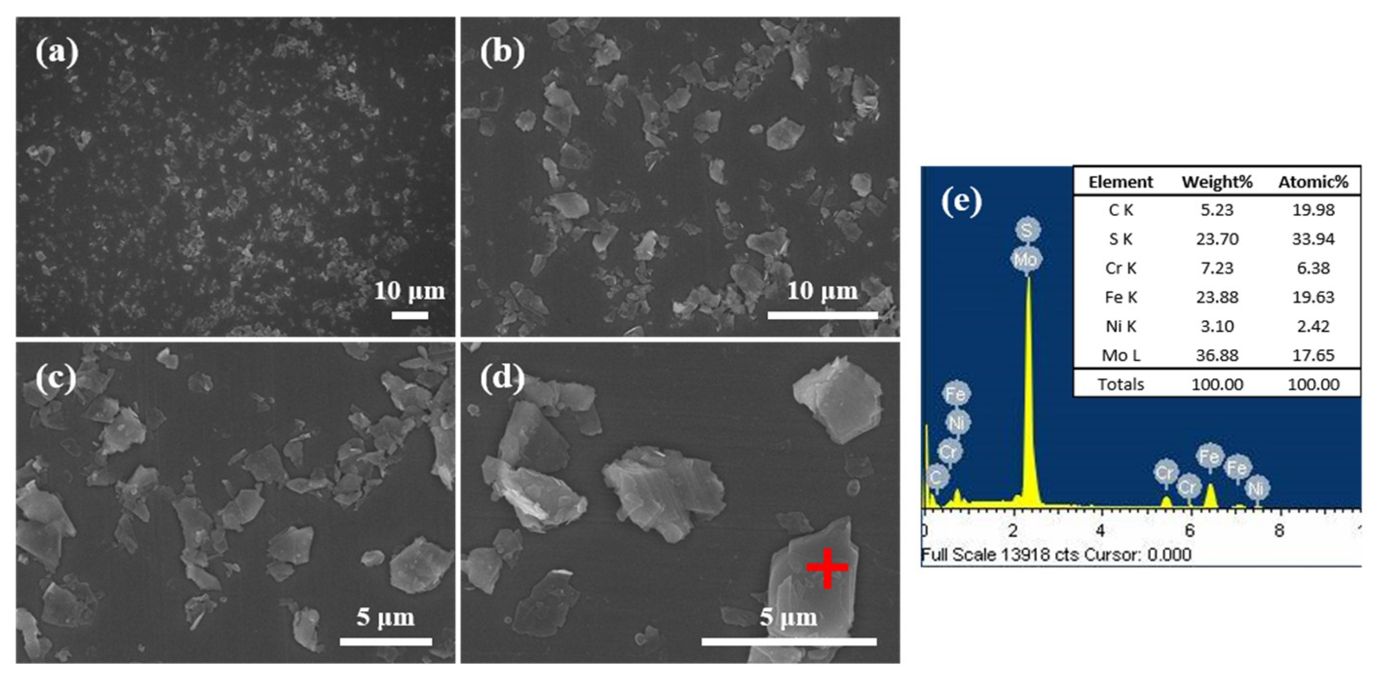
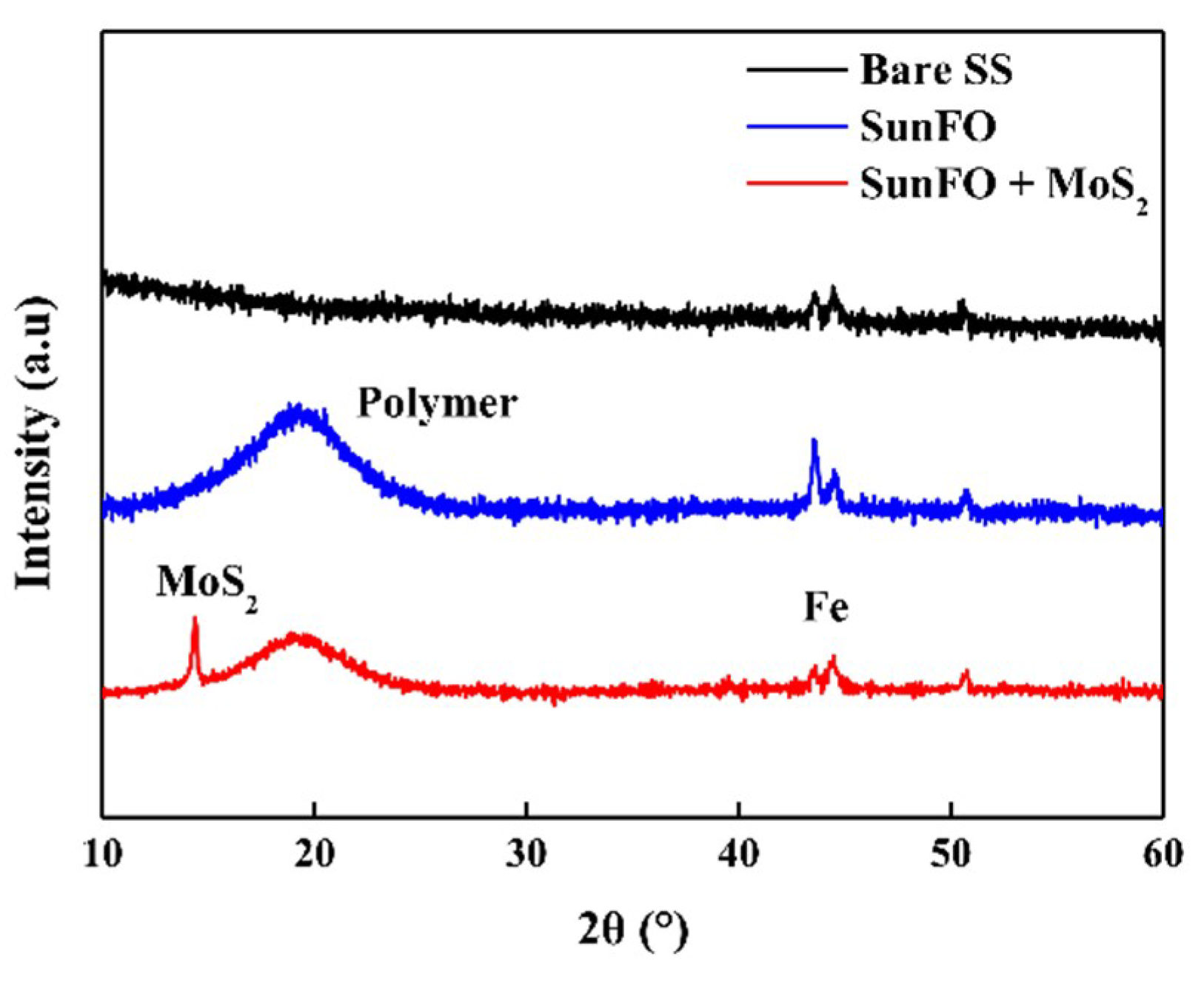
  • The SEM images of SunFO with MoS2 coating film showed the presence of a large number of MoS2 flakes which averaged 1–3 µm evenly on the entire surface. The XRD results showed that the crystalline nature and orientation of the MoS2 have strong and sharp peaks, which are the (002) peak corresponding to the angle of 15°.
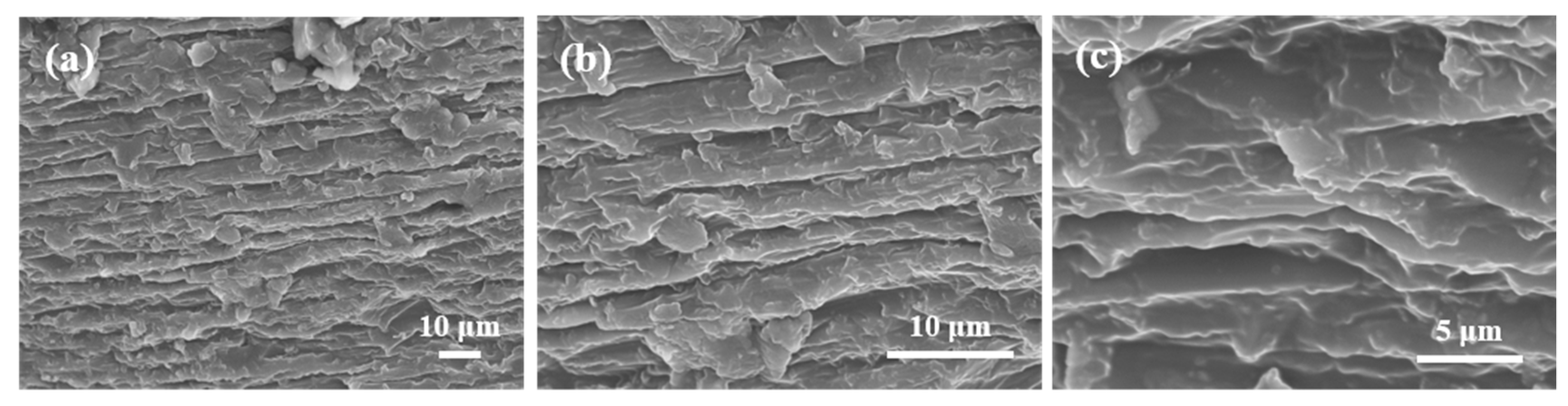
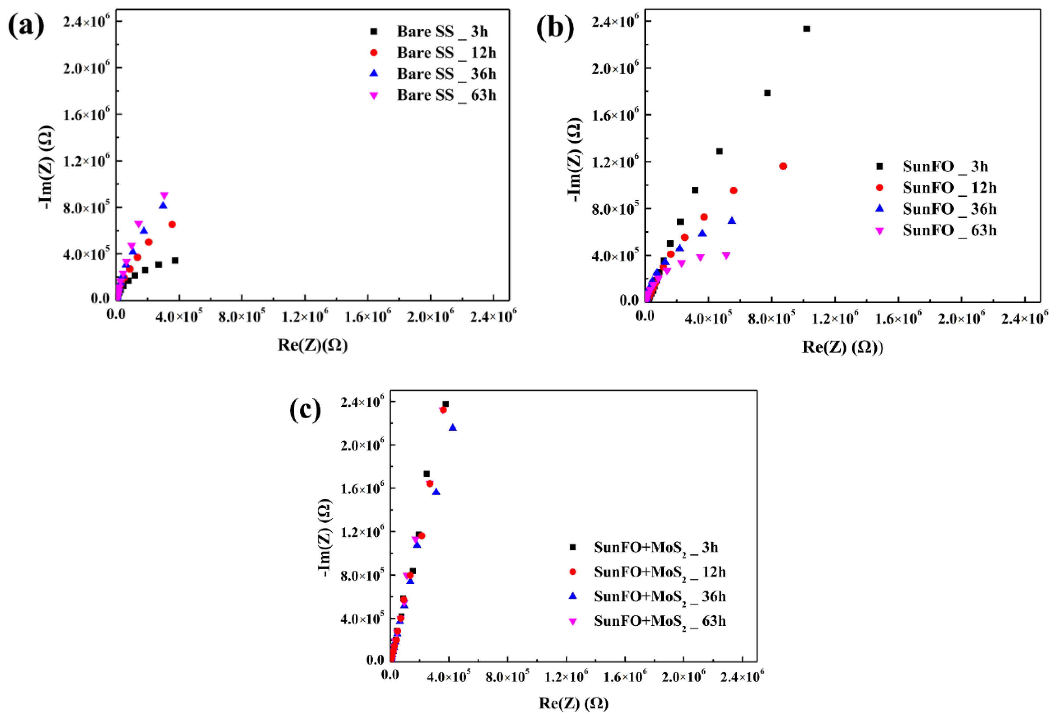
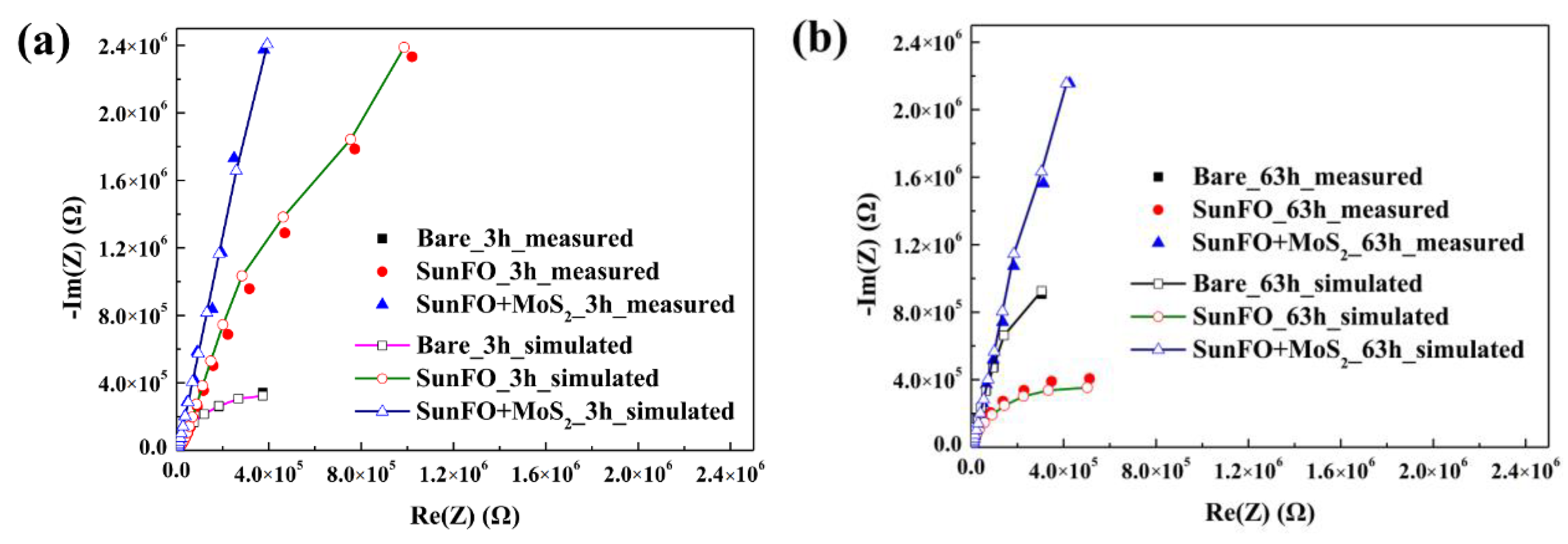
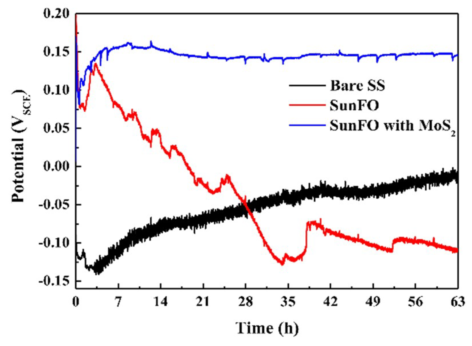
  • In the EIS results, the bare SS showed stable passive film generation during the test time. The SunFO with the MoS2 coating on the SS surface showed the largest coating resistance and durability throughout the immersion time compared to SunFO coating and bare specimen. This is because the interaction with the aggregations of the SunFO lamellar structure and MoS2 in coating film acted as a high order layer barrier to protect the metals against electrolytes.
Consequently, the incorporating MoS2 in organic coatings could considerably improve the localized corrosion resistance of stainless steel in high chloride environment.

Author Contributions

Experiments Conception and Design, M.-S.H., Y.P., J.G.K. and K.K.; Experiment Performance, M.-S.H. and Y.P.; Data Analysis, M.-S.H., Y.P., J.G.K. and K.K.; Manuscript Writing, M.-S.H., Y.P., J.G.K. and K.K.

Funding

This research was supported by the Basic Science Research Program through the National Research Foundation of Korea (NRF) funded by the Ministry of Science, ICT & Future Planning (NO. NRF-2017R1C1B2011750). This research was supported by the program for fostering next-generation researchers in engineering of National Research Foundation of Korea (NRF) funded by the Ministry of Science and ICT (No. 2017H1D8A2031628). This work was supported by NRF (National Research Foundation of Korea) Grant funded by the Korean Government (NRF-2018-Fostering Core Leaders of the Future Basic Science Program/Global Ph.D. Fellowship Program) (No. NRF-2018H1A2A1062418).

Conflicts of Interest

The authors declare no conflict of interest.

References

  1. Uhlig, H.H.; King, C. Corrosion and corrosion control. J. Electrochem. Soc. 1972, 119, 327C. [Google Scholar] [CrossRef]
  2. Galliano, F.; Landolt, D. Evaluation of corrosion protection properties of additives for waterborne epoxy coatings on steel. Prog. Org. Coat. 2002, 44, 217–225. [Google Scholar] [CrossRef]
  3. Kain, R.M. Metal Handbook; ASM International: Novelty, OH, USA, 1987; Volume 13. [Google Scholar]
  4. Fossati, A.; Borgioli, F.; Galvanetto, E.; Bacci, T. Corrosion resistance properties of glow-discharge nitrided AISI 316L austenitic stainless steel in NaCl solutions. Corros. Sci. 2006, 48, 1513–1527. [Google Scholar] [CrossRef]
  5. Streicher, M. Pitting corrosion of 18Cr-8Ni stainless steel. J. Electrochem. Soc. 1956, 103, 375–390. [Google Scholar] [CrossRef]
  6. Uhlig, H.H. Uhlig’s Corrosion Handbook; John Wiley & Sons: New York, NY, USA, 2011. [Google Scholar]
  7. Tsai, W.-T.; Chen, M.-S. Stress corrosion cracking behavior of 2205 duplex stainless steel in concentrated NaCl solution. Corros. Sci. 2000, 42, 545–559. [Google Scholar] [CrossRef]
  8. Erciyes, A.T.; Erkal, F.S.; Kalipci, A. Oil-modified alkyd type resin based on secondary esters of castor oil. J. Coat. Technol. 1993, 65, 73–78. [Google Scholar]
  9. Lligadas, G.; Ronda, J.C.; Galia, M.; Cadiz, V. Renewable polymeric materials from vegetable oils: A perspective. Mater. Today 2013, 16, 337–343. [Google Scholar] [CrossRef]
  10. Alam, M.; Akram, D.; Sharmin, E.; Zafar, F.; Ahmad, S. Vegetable Oil Based Eco-Friendly Coating Materials: A Review Article. Arabian J. Chem. 2014, 7, 469–479. [Google Scholar] [CrossRef]
  11. Singhbabu, Y.N.; Sivakumar, B.; Singh, J.K.; Bapari, H.; Pramanick, A.K.; Sahu, R.K. Efficient anti-corrosive coating of cold-rolled steel in a seawater environment using an oil-based graphene oxide ink. Nanoscale 2015, 7, 8035–8047. [Google Scholar] [CrossRef]
  12. Balakrishnan, T.; Sathiyanarayanan, S.; Mayavan, S. Advanced anticorrosion coating materials derived from sunflower oil with bifunctional properties. ACS Appl. Mater. Interfaces 2015, 7, 19781–19788. [Google Scholar] [CrossRef]
  13. Bhimanapati, G.R.; Lin, Z.; Meunier, V.; Jung, Y.; Cha, J.; Das, S.; Xiao, D.; Son, Y.; Strano, M.S.; Cooper, V.R. Recent advances in two-dimensional materials beyond graphene. ACS Nano 2015, 9, 11509–11539. [Google Scholar] [CrossRef] [PubMed]
  14. Butler, S.Z.; Hollen, S.M.; Cao, L.; Cui, Y.; Gupta, J.A.; Gutiérrez, H.R.; Heinz, T.F.; Hong, S.S.; Huang, J.; Ismach, A.F. Progress, challenges, and opportunities in two-dimensional materials beyond graphene. ACS Nano 2013, 7, 2898–2926. [Google Scholar] [CrossRef] [PubMed]
  15. Spear, J.C.; Ewers, B.W.; Batteas, J.D. 2D-nanomaterials for controlling friction and wear at interfaces. Nano Today 2015, 10, 301–314. [Google Scholar] [CrossRef] [Green Version]
  16. Britto, R.J.; Benck, J.D.; Young, J.L.; Hahn, C.; Deutsch, T.G.; Jaramillo, T.F. Molybdenum disulfide as a protection layer and catalyst for gallium indium phosphide solar water splitting photocathodes. J. Phys. Chem. Lett. 2016, 7, 2044–2049. [Google Scholar] [CrossRef]
  17. Choi, J.; Zhang, H.; Du, H.; Choi, J.H. Understanding solvent effects on the properties of two-dimensional transition metal dichalcogenides. ACS Appl. Mater. Interfaces 2016, 8, 8864–8869. [Google Scholar] [CrossRef]
  18. Bandaru, N.; Kumar, R.S.; Sneed, D.; Tschauner, O.; Baker, J.; Antonio, D.; Luo, S.-N.; Hartmann, T.; Zhao, Y.; Venkat, R. Effect of pressure and temperature on structural stability of MoS2. J. Phys. Chem. C 2014, 118, 3230–3235. [Google Scholar] [CrossRef]
  19. Shankara, A.; Menezes, P.L.; Simha, K.; Kailas, S.V. Study of solid lubrication with MoS2 coating in the presence of additives using reciprocating ball-on-flat scratch tester. Sadhana 2008, 33, 207–220. [Google Scholar] [CrossRef]
  20. Joensen, P.; Crozier, E.; Alberding, N.; Frindt, R. A study of single-layer and restacked MoS2 by X-ray diffraction and X-ray absorption spectroscopy. J. Phys. C Solid State Phys. 1987, 20, 4043. [Google Scholar] [CrossRef]
  21. Jones, D.A. Principles and Prevention of Corrosion, 2nd ed.; Prentice Hall: Upper Saddle River, NJ, USA, 1996. [Google Scholar]
  22. Hong, T.; Sun, Y.H.; Jepson, W.P. Study on corrosion inhibitor in large pipelines under multiphase flow using EIS. Corros. Sci. 2002, 44, 101–112. [Google Scholar] [CrossRef]
  23. Boissy, C.; Alemany-Dumont, C.; Normand, B. EIS evaluation of steady-state characteristic of 316L stainless steel passive film grown in acidic solution. Electrochem. Commun. 2013, 26, 10–12. [Google Scholar] [CrossRef]
  24. Mohammadi, F.; Nickchi, T.; Attar, M.; Alfantazi, A. EIS study of potentiostatically formed passive film on 304 stainless steel. Electrochim. Acta 2011, 56, 8727–8733. [Google Scholar] [CrossRef]
  25. Simoes, A.; Ferreira, M.; Rondot, B.; Da Cunha Belo, M. Study of passive films formed on AISI 304 stainless steel by impedance measurements and photoelectrochemistry. J. Electrochem. Soc. 1990, 137, 82–87. [Google Scholar] [CrossRef]
  26. Nam, N.D.; Kim, J.G. Effect of niobium on the corrosion behaviour of low alloy steel in sulfuric acid solution. Corros. Sci. 2010, 52, 3377–3384. [Google Scholar] [CrossRef]
  27. Lee, D.Y.; Kim, W.C.; Kim, J.G. Effect of nitrite concentration on the corrosion behaviour of carbon steel pipelines in synthetic tap water. Corros. Sci. 2012, 64, 105–114. [Google Scholar] [CrossRef]
  28. Lopez, D.A.; Simison, S.; De Sanchez, S. The influence of steel microstructure on CO2 corrosion. EIS studies on the inhibition efficiency of benzimidazole. Electrochim. Acta 2003, 48, 845–854. [Google Scholar] [CrossRef]
  29. Alves, V.A.; Brett, C.M. Characterization of passive films formed on mild steels in bicarbonate solution by EIS. Electrochim. Acta 2002, 47, 2081–2091. [Google Scholar] [CrossRef]
  30. Brown, R.; Alias, M.; Fontana, R. Effect of composition and thickness on corrosion behavior of TiN and ZrN thin films. Surf. Coat. Technol. 1993, 62, 467–473. [Google Scholar] [CrossRef]
  31. Hong, M.-S.; Park, I.-J.; Kim, J.-G. Alloying effect of copper concentration on the localized corrosion of aluminum alloy for heat exchanger tube. Met. Mater. Int. 2017, 23, 708–714. [Google Scholar] [CrossRef]
  32. Bessone, J.; Salinas, D.; Mayer, C.; Ebert, M.; Lorenz, W. An EIS study of aluminium barrier-type oxide films formed in different media. Electrochim. Acta 1992, 37, 2283–2290. [Google Scholar] [CrossRef]
  33. Mansfeld, F. Electrochemical impedance spectroscopy (EIS) as a new tool for investigating methods of corrosion protection. Electrochim. Acta 1990, 35, 1533–1544. [Google Scholar] [CrossRef]
  34. Tan, Y.-J.; Bailey, S.; Kinsella, B. An investigation of the formation and destruction of corrosion inhibitor films using electrochemical impedance spectroscopy (EIS). Corros. Sci. 1996, 38, 1545–1561. [Google Scholar] [CrossRef]
  35. Zeng, A.; Liu, E.; Annergren, I.; Tan, S.; Zhang, S.; Hing, P.; Gao, J. EIS capacitance diagnosis of nanoporosity effect on the corrosion protection of DLC films. Diam. Relat. Mater. 2002, 11, 160–168. [Google Scholar] [CrossRef]
  36. Cottis, R.; Turgoose, S. Electrochemical Impedance and Noise; National Assn of Corrosion Engineers: Houston, TX, USA, 1999. [Google Scholar]
  37. Manov, S.; Lamazouere, A.; Aries, L. Electrochemical study of the corrosion behaviour of zinc treated with a new organic chelating inhibitor. Corros. Sci. 2000, 42, 1235–1248. [Google Scholar] [CrossRef]
  38. Rondelli, G.; Torricelli, P.; Fini, M.; Rimondini, L.; Giardino, R. In vitro corrosion study by EIS of an equiatomic NiTi alloy and an implant quality AISI 316 stainless steel. J. Biomed. Mater. Res. B Appl. Biomater. 2006, 79, 320–324. [Google Scholar] [CrossRef] [PubMed]
  39. Hong, M.-S.; Hwang, J.-H.; Kim, J.H. Optimization of the Cathodic Protection Design in Consideration of the Temperature Variation for Offshore Structures. Corrosion 2017, 74, 123–133. [Google Scholar] [CrossRef]
  40. Bentiss, F.; Jama, C.; Mernari, B.; El Attari, H.; El Kadi, L.; Lebrini, M.; Traisnel, M.; Lagrenée, M. Corrosion control of mild steel using 3,5-bis (4-methoxyphenyl)-4-amino-1,2,4-triazole in normal hydrochloric acid medium. Corros. Sci. 2009, 51, 1628–1635. [Google Scholar] [CrossRef]
  41. Hong, M.-S.; Kim, S.-H.; Im, S.-Y.; Kim, J.-G. Effect of ascorbic acid on the pitting resistance of 316L stainless steel in synthetic tap water. Met. Mater. Int. 2016, 22, 621–629. [Google Scholar] [CrossRef]
  42. Hassan, H.H.; Abdelghani, E.; Amin, M.A. Inhibition of mild steel corrosion in hydrochloric acid solution by triazole derivatives: Part I. Polarization and EIS studies. Electrochim. Acta 2007, 52, 6359–6366. [Google Scholar] [CrossRef]
  43. Liangcai, L.; Ming, W.; Huoming, S.; Haiying, L.; Qingdong, Q.; Yuanlong, D. Preparation and EIS studies on polyimide/polyaniline blend film for corrosion protection. Polym. Adv. Technol. 2001, 12, 720–723. [Google Scholar] [CrossRef]
  44. Zin, I.; Lyon, S.; Hussain, A. Under-film corrosion of epoxy-coated galvanised steel: An EIS and SVET study of the effect of inhibition at defects. Prog. Org. Coat. 2005, 52, 126–135. [Google Scholar] [CrossRef]
  45. Marangoni, A.G.; Acevedo, N.; Maleky, F.; Peyronel, F.; Mazzanti, G.; Quinn, B.; Pink, D. Structure and functionality of edible fats. Soft Matter 2012, 8, 1275–1300. [Google Scholar] [CrossRef]
  46. Acevedo, N.C.; Marangoni, A.G. Nanostructured fat crystal systems. Annu. Rev. Food Sci. Technol. 2015, 6, 71–96. [Google Scholar] [CrossRef] [PubMed]
  47. Nan, H.; Wang, Z.; Wang, W.; Liang, Z.; Lu, Y.; Chen, Q.; He, D.; Tan, P.; Miao, F.; Wang, X.; et al. Strong photoluminescence enhancement of MoS2 through defect engineering and oxygen bonding. ACS Nano 2014, 8, 5738–5745. [Google Scholar] [CrossRef] [PubMed]
  48. Hu, X.; Jiang, P.; Wan, J.; Xu, Y.; Sun, X. Study of corrosion and friction reduction of electroless Ni-P coating with molybdenum disulfide nanoparticles. J. Coat. Technol. Res. 2009, 6, 275–281. [Google Scholar] [CrossRef]
  49. Rad, N.E.; Dehghanian, C. Effects of co-deposition of Cr2O3 and MoS2 on corrosion properties of nanocomposite electroless nickel coating. Iran. J. Mater. Sci. Eng. 2010, 7, 1–7. [Google Scholar]
Figure 1. Schematic diagram of the experimental procedures and expected coating structure.
Coatings 09 00045 g001
Figure 2. Surface morphology of sunflower oil (SunFO) with molybdenum disulfide (MoS2) coating on the stainless steel (SS) observed by SEM and EDS: (a) 1000×; (b) 3000×; (c) 5000×; (d) 10000×; (e) EDS results on the red spot.
Coatings 09 00045 g002
Figure 3. Cross sectional images of SunFO with MoS2 coating on the SS observed by SEM and EDS: (a) 10000× (Cross-section of the specimen); (b) Fe observed by EDS mapping; (c) Mo observed by EDS mapping; (d) S observed by EDS mapping.
Coatings 09 00045 g003
Figure 4. SEM images of unpolished SunFO with MoS2 coating on the SS observed by SEM: (a) 1000×; (b) 3000×; (c) 5000×.
Coatings 09 00045 g004
Figure 5. XRD results of (a) Bare SS; (b) SunFO coated SS; (c) SunFO with MoS2 coated SS.
Coatings 09 00045 g005
Figure 6. Electrochemical impedance spectroscopy (EIS) results in the form of Nyquist plot in 3.5% NaCl solution; (a) Bare SS; (b) SunFO coated SS; (c) SunFO + MoS2 coated SS.
Coatings 09 00045 g006
Figure 7. Time-dependent EIS results in the form of Nyquist plot in 3.5% NaCl solution: (a) initial stage (3 h); (b) final stage (63 h).
Coatings 09 00045 g007
Figure 8. Open-circuit potential of specimens during the immersion time.
Coatings 09 00045 g008
Figure 9. EIS results in the form of Bode plot in 3.5% NaCl solution: (a) Bare SS; (b) SunFO coated SS; (c) SunFO + MoS2 coated SS.
Coatings 09 00045 g009
Figure 10. An equivalent circuit used to fit the results of the EIS tests: (a) one-time constant circuit; (b) two-time constant circuit.
Coatings 09 00045 g010
Table 1. Chemical Composition of 316L stainless steel (wt.%).
ElementsComposition
FeBalance
C0.03 Max.
Cr16–18
Ni10–14
Mo2–3
S0.03 Max.
Table 2. EIS results of specimens according to the coating materials.
SpecimenTimeRs (Ω cm2)CPE1 (Cfilm) (F/cm2)n1Rfilm (Ω cm2)CPE2 (Cdl) (F/cm2)n2Rct (Ω cm2)n3CPE3 (Ccoating) (F/cm2)Rcoating (Ω cm2)
Bare3118.91.37 × 10−50.929.85 × 1042.06 × 10−60.371.01 × 106
12118.21.37 × 10−50.915.65 × 1051.88 × 10−60.611.83 × 106
36119.51.34 × 10−70.913.91 × 1063.74 × 10−60.802.14 × 106
63120.14.73 × 10−60.912.12 × 1077.61 × 10−60.832.12 × 107
SunFO3120.47.72 × 10−70.931.22 × 1041.88 × 10−60.836.33 × 1070.802.31 × 10−44.38 × 10⁻⁶
12127.62.39 × 10−60.883.19 × 1043.61 × 10−60.774.88 × 105
36134.14.55 × 10−70.86181.57.39 × 10−60.911.58 × 106
63126.97.66 × 10−80.81427.74.80 × 10−60.949.05 × 105
SunFO + MoS23135.74.80 × 10−50.56223.56.20 × 10−70.971.01 × 1040.905.12 × 10−62.836 × 10⁹
12135.15.05 × 10−50.56238.54.65 × 10−711.48 × 1040.905.29 × 10−63.05 × 10¹⁰
36141.43.76 × 10−50.6367424.50 × 10−50.773.48 × 1070.894.96 × 10−61.34 × 10¹⁴
63140.14.52 × 10−50.6068552.69 × 10−50.981.24 × 1090.895.07 × 10−61.19 × 10¹⁶

