Design, Fabrication, and Testing of an IoT Healthcare Cardiac Monitoring Device †
by
 , ,
, ,
Ionel Zagan
1,2,* ,
,
Vasile Gheorghiță Găitan
1,2,
Adrian-Ioan Petrariu
1,2 ,
,
Nicolai Iuga
1 and
Adrian Brezulianu
3 1
Faculty of Electrical Engineering and Computer Science, Stefan cel Mare University, 720229 Suceava, Romania
2
Integrated Center for Research, Development and Innovation in Advanced Materials, Nanotechnologies, and Distributed Systems for Fabrication and Control (MANSiD), Stefan cel Mare University, 720229 Suceava, Romania
3
“Gheorghe Asachi” Technical University of Iaşi, 700050 Iaşi, Romania
*
Author to whom correspondence should be addressed.
†
This paper is an extension of the conference paper: Zagan, I.; Găitan, V.G.; Iuga, N.; Brezulianu, A. m-GreenCARDIO embedded system designed for out-of-hospital cardiac patients. In the Proceedings of the 2018 International Conference on Development and Application Systems (DAS), Suceava, Romania, 24–26 May 2018.
Computers 2020, 9(1), 15; https://0-doi-org.brum.beds.ac.uk/10.3390/computers9010015
Submission received: 23 January 2020
/
Revised: 11 February 2020
/
Accepted: 20 February 2020
/
Published: 27 February 2020
(This article belongs to the Special Issue Machine Intelligence-Based Sensor Technologies for Scalable IoT Network Infrastructure and Applications)
Abstract
:The expansion of the concept of the Internet of Things (IoT), together with wireless sensor networks, has given rise to a wide range of IoT applications. This paper presents and describes the concept, theory of operation, and practical results of a Telecare-ECG (Electrocardiogram) Monitoring device, designed for the remote monitoring of out-of-hospital cardiac patients. ECG monitoring using the Telecare-ECG Monitor system ensures a better quality of life for patients and greater possibilities for the real-time monitoring and signaling of sporadic cardiac events, by recording instantaneous cardiac arrhythmias captured during certain activities or in the daily environment of the patient; furthermore, hospital resources are less impacted by this device than other devices. In accordance with the novelty and contribution of this paper to the field of ECG investigations, the results obtained in the analysis, testing, and validation of the Telecare-ECG Monitor system refer to the optimization of the functionality of the mobile ECG device under conditions that were as similar to reality as possible.
1. Introduction
Cyber-Physical Systems are the next evolutionary step from existing embedded systems and field-programmable gate arrays (FPGAs). In addition to the Internet and online services and data, embedded systems have been combined to form Cyber-Physical Systems (CPSs). CPSs provide the basis for creating the Internet of Things. Their role is to validate technologies that turn innovative processes and applications into reality so that, in the future, the borders between the real and the virtual will disappear. As a result, these systems promise to revolutionize our interactions with the physical world, just as the Internet has transformed communication and personal interactions [1]. Terms like real-time systems, real-time operating systems, FPGAs, and microcontrollers are closely connected to embedded systems and their future versions, CPSs.
Today’s electronic systems have evolved greatly, ushering in the design and fabrication of systems that are safer, more competitive, and more flexible in terms of their built-in features and power consumption. Indeed, the number of applications in the medical field and adjacent areas has increased exponentially so that monitoring terminals or mobile analysis systems can be purchased relatively easily and at affordable prices. As a requirement for most markets, IEC60601—a series of technical standards dedicated to safety and the performance of medical electrical equipment, published by the International Electrotechnical Commission—represents solid support for many companies to provide medical devices that are effective and safe.
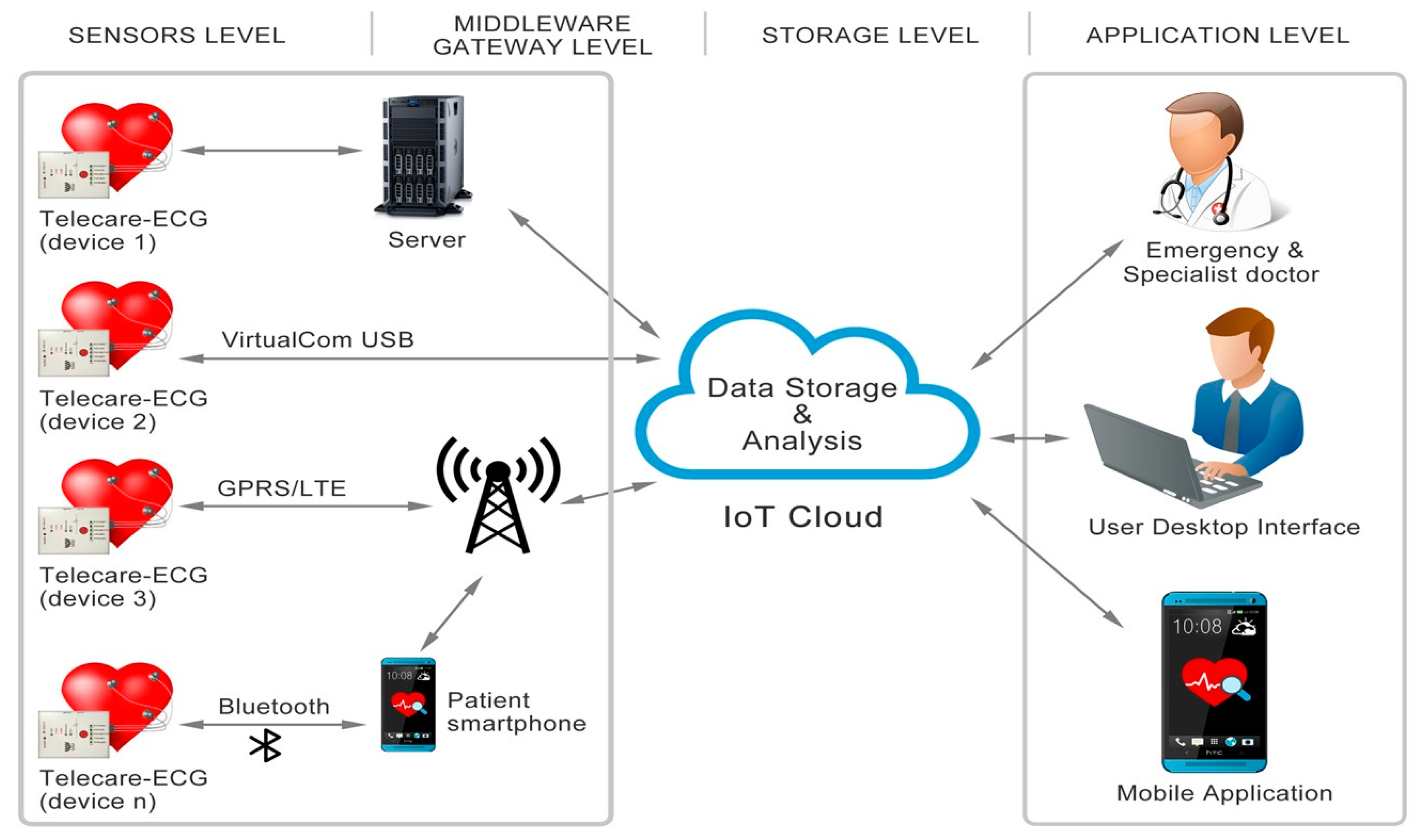
In this paper, we propose a new embedded device for ECG monitoring based on Internet of Things (IoT) techniques [2]. Our main contribution is the implementation of a reliable mobile system for unobtrusive and easy-to-use healthcare solutions in order to facilitate the continuous monitoring of health. The Telecare-ECG Monitor system architecture is shown in Figure 1, which illustrates the modules for acquiring and transmitting data corresponding to the ECG measurements, the IoT Cloud, and the user interface.
The present paper is structured as follows. The first section contains an overview of the systems designed to acquire ECG signals based on IoT. Section 2 briefly presents the proposed telemedicine projects and alternative solutions based on IoT technology. Section 3 is dedicated to theoretical aspects associated with the operation of the Telecare-ECG Monitor system, and Section 4 describes the microcontroller software development, project validation, and practical results. The last sections present a discussion, the conclusions, contributions, and future research directions.
2. Related Work
With the development of the concept of the Internet of Medical Things ([3,4]) for GSM/GPRS infrastructure and wireless communications (M2M), patients no longer depend on landline networks. Therefore, the evolution of embedded systems represents an important step new IoT applications [5]. The first mobile telemedicine systems were able to transmit patients’ parameters to, for example, ambulances for remote assistance and the preparation of emergency services.
In the past, Siemens attempted an alliance with Philips in order to develop a digital solution for cardiac monitoring using phone landlines. Since the late 1980s, telemedicine projects in the field of cardiology have been developed in hospitals in various European countries (Scotland, Greece, France, Sweden, Greenland, etc.), but also in the United States, especially in areas with low population densities. Probably the best known project is EPI-MEDICS [6], resulting from a collaboration between French, Italian, and Swedish researchers (2001–2004). The aim of this project was the development of an electrocardiograph (personal ECG monitor) with three electrodes for the early detection of myocardial ischemia and various heart diseases.
In the following part of the paper, we will consider similar projects that made significant contributions to this field. We will analyze the practical and theoretical aspects of the platforms used for its implementation, as well as the real-time characteristics of the processor and communication interfaces used in the projects. The architectures of the considered projects are generally scalable relative to the characteristics of the used microcontroller or FPGA.
The authors’ objectives in the project described in [7] were to present an Internet-connected monitoring platform for intravenous (IV) drip chambers. This previous paper provides details about how to implement and test a monitoring system retrofittable in an existing IV setup. The authors describe the procedure for estimating the liquid level from the capacitance, indicating the oscillation frequency with respect to the capacitance values, as well as the liquid level from the frequency of oscillation. One of the main features of the proposed device is its connectivity to the Internet in the field of the Internet of Medical Things.
The project detailed in [8] presents an implementation based on FPGA for the real-time monitoring of cardiac patients. This project used a SPARTAN-6 XC6SLX16 FPGA circuit and the MicroBlaze processor provided by Xilinx. For performance testing and evaluation, the authors used the MIT-BIH Arrhythmia Database [9] together with a supplementary module based on a Digital to Analog Converter (DAC). The authors used three processors implemented in the FPGA reconfigurable area as follows. The MB0 processor was implemented for the real-time collection of data from electrodes situated on the patient’s body; MB1 was the second processor implemented in FPGA, which executed tasks that did not require a real-time response; MB2 controlled and coordinated the MB0 and MB1 slave processors through special functions dedicated to the inter-processor communication FSL interface (transmitting data—putfsl(date, id) and receiving data—getfsl(date, id)). For more detailed information on the connections between these three processors, see the graphic description in the article [8]. The resources needed to implement this project were only 94% of the FPGAs Xilinx Spartan-6 XC6SLX16’s resources, because the system was optimized through the hardware/software CoDesign techniques.
In 2016, Ukil et al. discussed a new IoT Healthcare Analytics system, as well as the importance of a higher accuracy rate for detecting anomalies [10]. Since embedded healthcare applications based on IoT concepts have been developed substantially in the last few years, today’s systems can offer almost unlimited solutions for the analytical predictability in healthcare, accessible remote medical services, and arrhythmia databases. Park et al. used the MIT-BIT arrhythmia database to validate the proposed Wireless system. The implementation results demonstrated that the proposed solution can reach a proper Quality of Service (QoS) level for real-time ECG monitoring if the link-level error control is correctly implemented [11]. The major contributions of the authors relate to an innovative and flexible QoS assessment framework for wireless healthcare services that can be easily extended to support various networks and mobile devices. On the other hand, the authors argue that they can determine the size of the jitter buffer needed to avoid service dropouts due to buffer underflows, thereby ensuring increased reliability in ECG monitoring. In comparison to the implementations based on FPGA [8] that improve real-time features via the hardware parallelization of the application’s tasks, the Telecare-ECG Monitor project described in the present paper is favored due to the designing and debugging tools provided by the Keil uVision 5 development software, the implementation concept of the IoT Healthcare system, and the ADAS1000 circuit from Analog Devices. However, the Telecare-ECG Monitor embedded system was not only designed as a portable device for out-of-hospital cardiac patients. The various hardware/software implementations proposed in the literature based on IoT have led to scalable embedded systems [12], greater flexibility in production, and innovative healthcare solutions.
3. Concept and Theory of Operation of the Telecare-ECG Monitor System
The Telecare-ECG Monitor system, based on the IoT concept, will allow medical instruments to be more efficient and available for patient use, thereby making it accessible to a larger range of people. Through this project, ECG data from patients can be accurately and flexibly acquired, thus supplying valuable information that can be used for remote interpretation and diagnosis. With the vital need to save energy, the solution chosen for the implementation of this project must be reliable and scalable, to achieve rapid assessments and to significantly reduce the time to market launch. For example, through the hSensor platform (MAX30101: high-sensitivity pulse oximeter and heart-rate sensor), a wearable ECG module can be designed with an energy efficiency of more than 50% compared to the existing solutions.
Today’s electronic embedded systems are advanced in many ways, such as offering low power consumption, increased processing power, the implementation of multiple communications interfaces, and the easy integration of the IoT. In the area of telecare applications, the actual projects in the field based on multi-sensor platforms allow the continuous monitoring of patients and enable health and social services to be more preventative and anticipatory. Based on these technological innovations, current medical information systems monitor out-of-hospital cardiac patients in their home environments as accurately as possible. The IoT healthcare cardiac monitoring device presented in this paper is a telemedicine project that represents a link between the general practitioner and the cardiologist and favors the possibility of a “remote” interpretation of electrocardiograms for out-of-hospital cardiac patients. The beneficiaries of this system are patients living in rural or inaccessible areas, patients who cannot be transported, or patients who want to monitor their medical condition without going to see a specialist. The objective of this project is to develop research in order to obtain solutions for the online monitoring of patients in a medical clinic or at home. Thus, the novelty of the present paper is in developing a mobile device in order to comfortably collect ECG data from cardiac patients, process the ECG signal and continuously or periodically store the corresponding values for each patient, and transmit those values to a server.
Choosing the right connectivity technology is one of the most critical decisions in developing an IoT system [13]. If there is not a perfect match, there can be a loss in performance or an unnecessary increase in production and design costs. In the worst case scenario (a scenario that does not produce cost and labor changes), long-term scalability can be limited. Among other applications for the smart building sector, IoT solutions can produce financial benefits in balancing the energy used for heating and ventilation according to one’s set preferences.
To ensure the proper operation of IoT devices, a few basic elements, such as power, communications, and storing data by using memory card slots, must be considered from the first design phases. In the case of wireless communications in the field of IoT devices, antennas represent one of the primary access methods, enabling connection to the network via GSM, WIFI, Bluetooth, Z-Wawe, or Zigbee. Thus, when designing the printed circuit board (PCB), we had to pay special attention to both the research on and the integration of a 2.4 GHz miniature antenna. With regards to storing information from sensors, large quantities of recorded data can be sent online to the IoT cloud, where they are subsequently stored and processed. In relation to the flexibility of the ECG monitoring device, a memory card is ideal for local data backup in the case of network failures or other unforeseen events.
The heterogeneous nature of the decentralized Internet of Medical Things concept requires a flexible and layered architecture that eliminates, as much as possible, any bias towards a single information communication mechanism, operating system, or other technology and that makes efficient use of available network connectivity and energy consumption. In this case, it is necessary to facilitate the performance of actual embedded systems at all levels of the used technology, from the ECG signals to the visualization of data and determining arrhythmia situations for out-of-hospital cardiac patients. An ECG signal is bioelectric, with amplitudes in the range of 0.1–2 mV when measured in the human body surface. The frequency of this signal is in the range of 0.05–100 Hz, although an ECG signal can sometimes have smaller amplitudes or slightly different frequencies.
The Telecare-ECG Monitor system is an embedded device that records, with high speed, variations in the electrical current generated by the heart; the electrocardiograph amplifies these variations and displays them on a screen or transforms them into mechanical movements in order to print the ECG chart. Due to the outstanding performance of the microcontrollers available in today’s market, we can achieve remarkable flexibility for our application. Thus, the use of pipeline processors, coprocessors, Networks on a Chip (NoCs), and IoT services enabled the minimization of the response time and the implementation of innovative projects [14].
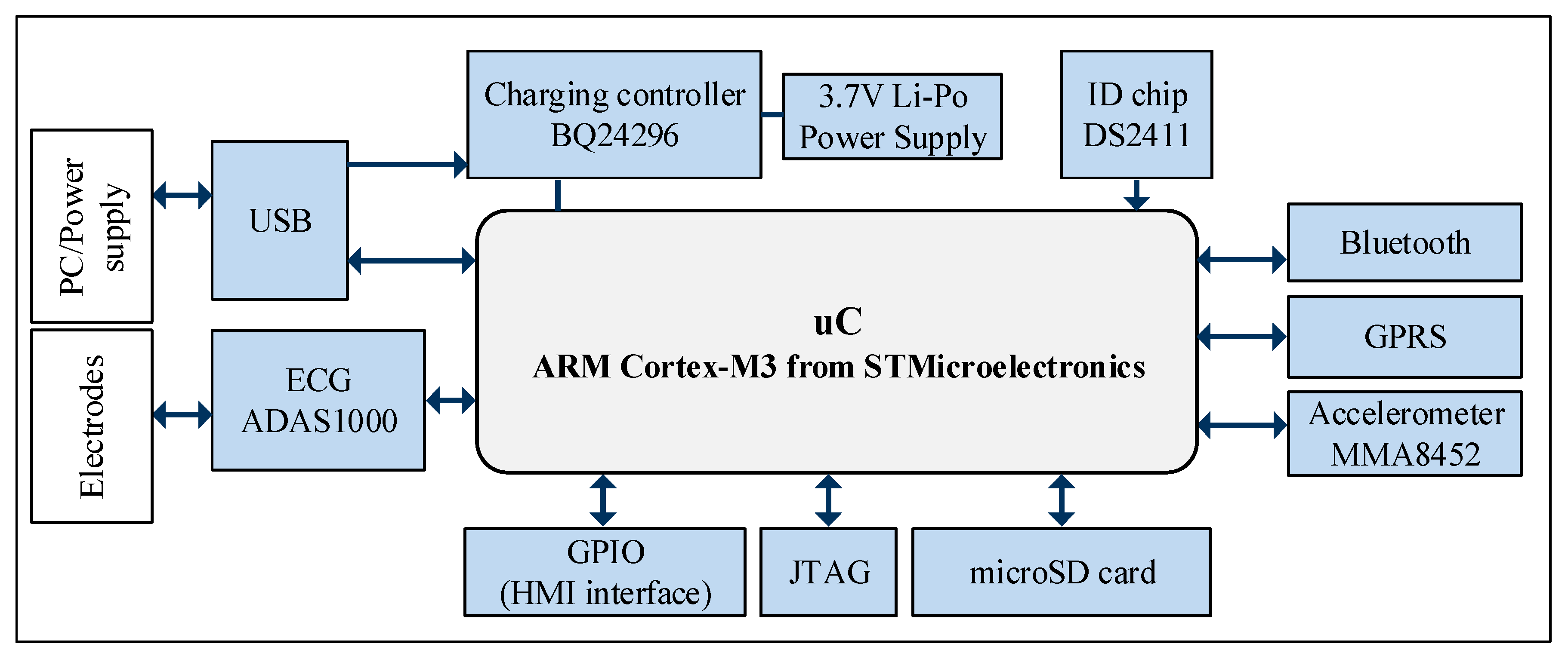
Figure 2 shows the block diagram of the Telecare-ECG Monitoring device based on the IEC60601 standard and the Internet of Medical Things.
The validation of data sent by all chains of wireless transmission and protocol conversion GSM/GPRS/3G/TCP-IP is performed at the segment level, and at the level of the communication channel, by encapsulating a package and validating the content with a 32-bit checksum. This procedure enables the integrity confirmation for each data package and, implicitly, of the entire channel. Increasing the computing power of the Telecare-ECG Monitoring device mainly involves increasing its energy consumption; thus, the entire system (accumulator, wireless mode, 3D mode, general control mode, A/D conversion mode, biomagnification mode, and sensors) must not weigh too much, so as not to become inconvenient to carry and to ensure autonomy for a minimum of 24 hours.
4. Presentation of the Practical Results Obtained During Validation of the Telecare-ECG Monitoring Device
The healthcare industry and the emergence of the Internet of Medical Things have been strongly standardized according to numerous rules and standards that designers must abide by. The IEC 60601 standard is recognized as a fundamental component in this regulatory framework. IEC 60601 is outlines a set of standards for electronic equipment, such as the Telecare-ECG Monitor embedded device, used in medical environments. These standards aim to ensure a higher degree of patient safety and also that the equipment is safe to use. First published in the 1970s, the standards covered by IEC60601 have been constantly developing over the years. The establishment of the fourth edition of the IEC60601 standard has strongly impacted OEMs (Original Equipment Manufacturers) operating in the medical sector. Considering that the time to market, including design, testing and compliance approval, is relatively long, OEMs need to consider this standard as soon as possible. One of the key elements of the updated standard is how medical devices for health monitoring can be used both inside and outside living buildings, as many patients are subsequently monitored out of hospital. For this reason, the updated standard incorporates new Electromagnetic Compatibility (EMC) related features, with different application parameters, including the home environment; nevertheless, these features explicitly address the potential interference generated by wireless sources, such as Wi-Fi or Bluetooth. Among other important aspects, electrical sources in the home cannot be as stable as those in a medical environment; moreover, the Telecare-ECG Monitor designed for everyday life is not used by health professionals, but by patients or their caregivers. IEC60601-1 is the basic standard for IEC60601, covering essential general safety requirements and performance for medical equipment. This standard relates to other collateral and particular standards, the latter addressing the specific performance requirements or requirements related to particular types of medical devices. One of the reasons that led to these specifications was an increase in the prevalence of wireless communications, both in the home of the patient and in the clinical environment. Thus, devices like medical information systems, smartphones, multi-sensor platforms, the Internet of Medical Things, and laptops or PCs for recording patient data are used, all of which must be taken into account when defining standards in this sector. For these reasons, it is imperative that medical equipment, such as the Telecare-ECG Monitor, must be able to operate safely without interference from wireless-based devices.
4.1. Materials and Fabrication Aspects
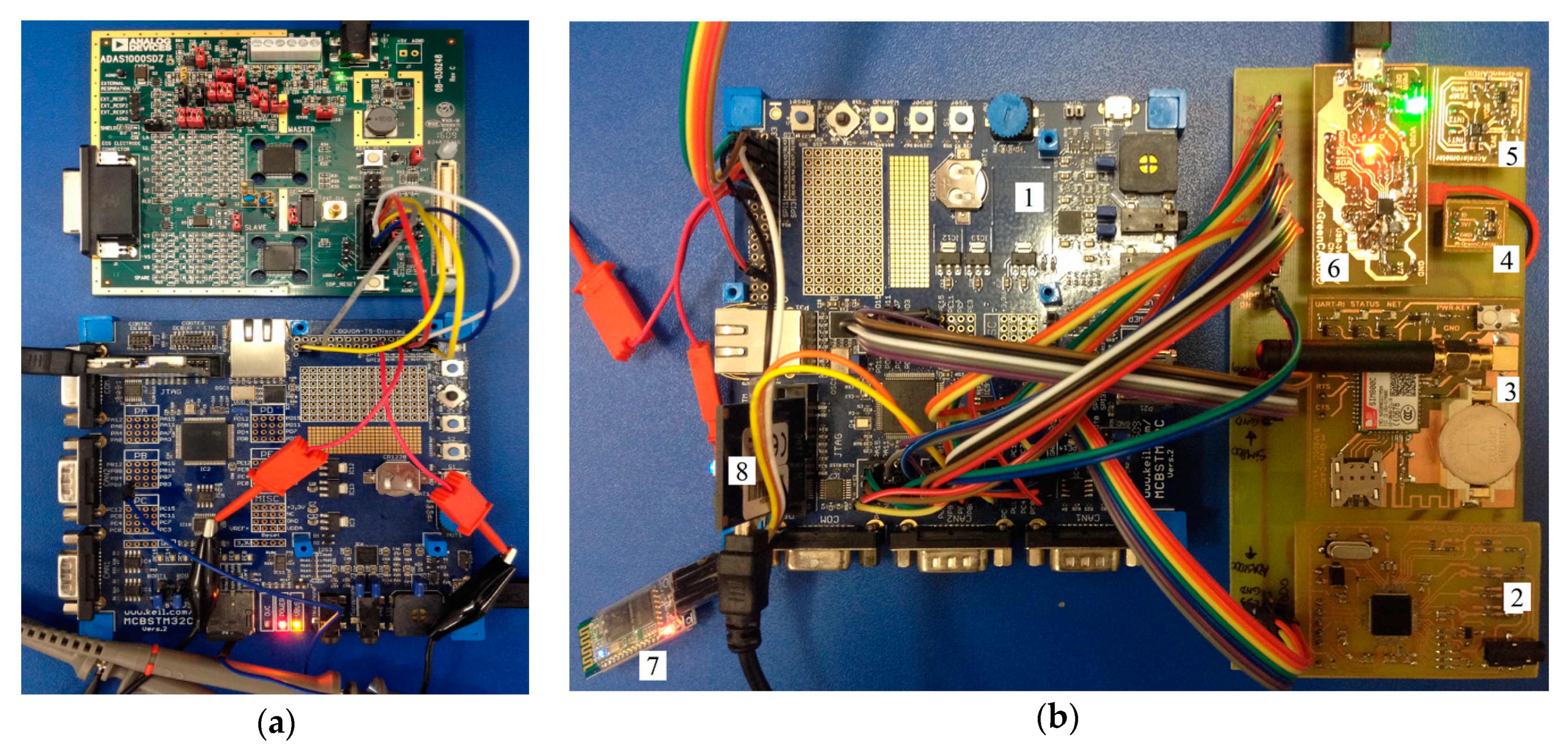
Keil MDK 5 is an environment designed by the Keil ARM Group Company used to create, build, and debug embedded applications. As the difficulty of the applications increases, the designer’s code has to control increasingly more concurrent jobs, and it becomes difficult to ensure that such applications run safely without an embedded OS. In this project, we use a typical embedded OS called Real-Time Executive (RTX) kernel [15]. A part of the embedded OS is called a Real-Time Operating Systems (RTOS), which provides both a predictable answer in a defined time period and a very fast context switching time. This application was developed by using the MCBSTM32C development board with the STM32F107 (Cortex-M3) microcontroller compatible pin-wise with the microcontroller chosen for the Telecare-ECG mobile (32L151), as well as the modules that are presented in Figure 3. The difference between the Cortex-M and Cortex-A microcontrollers is that the latter microcontroller has a Memory Management Unit (MMU) for remapping logical addresses to physical addresses [16], which is necessary for Linux systems. Cortex-M cannot have a virtual address support to run a fully-featured Linux system, but it has a valuable Memory Protection Unit (MPU).
The MMU does not introduce additional delays, guaranteeing a predictable response time for many real-time applications that use Cortex-M processors. In order to acquire ECG data, the processor is configured to execute task 0 with a periodicity of 10 ms (100 Hz) to read the ECG signal samples.
The Serial Peripheral Interface (SPI) between the processor and the ECG chip performs the serial transmission of digital data supplied by the Analog to Digital Converter (ADC) in the ECG module. In current embedded systems, the approach of such a project, using designs based on a single processor, is advantageous in terms of reducing energy consumption. Although the real-time tasks used for data acquisition are few in number, the complexity of the system cannot be greatly increased, as unpredictable situations are eliminated. The processing of the signals acquired from cardiac patients on the move is also an important objective for projects in this area [18]. Thus, various solutions have attempted to filter the disturbances caused by the patient’s movement or by the changes in the environment in which the patient is present (e.g., underground or in systems with strong perturbing induction or fluorescent lighting).
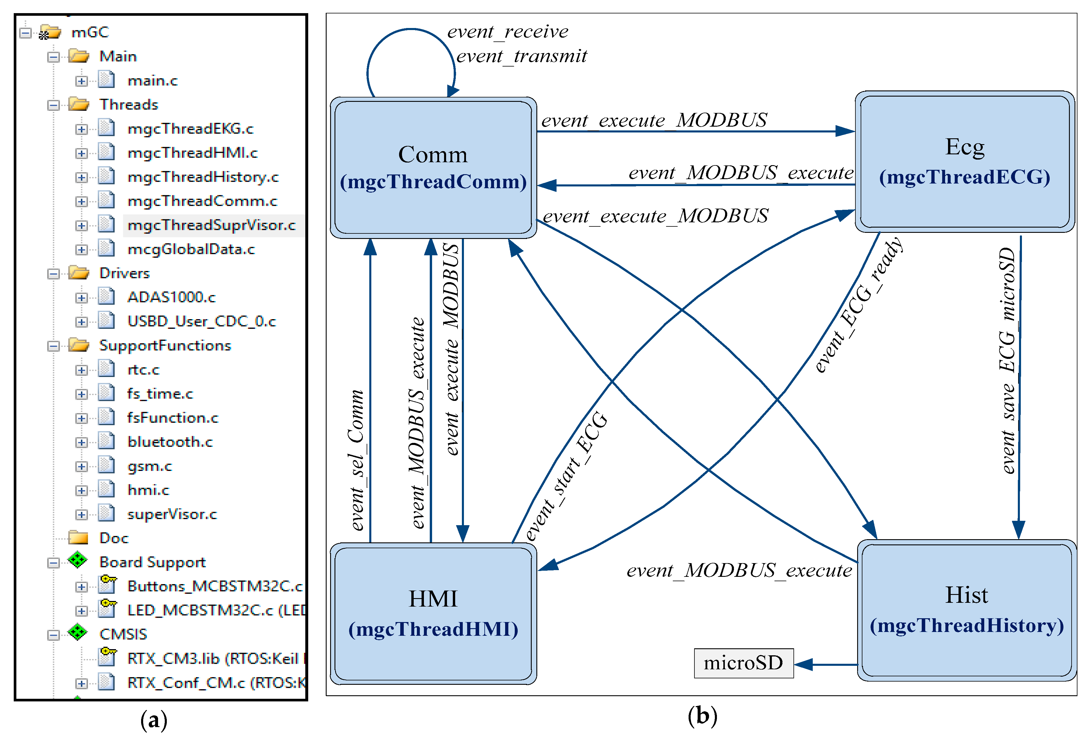
Below, we present the methodology and the steps performed in the designing and testing procedure. Figure 4a shows the mGC project structure and the organization of the application for the Telecare-ECG mobile device using the MDK 5.21a development environment.
MDK 5.21a from Keil uVision 5 features a powerful debugger that includes, among other elements, the step-by-step execution of program breakpoints for both program and data code, support for the operating system, as well as support for a function editor [19]. The microcontroller belongs to a low-power family, so the total current consumption will be approximately 43 mA.
The events presented in Figure 4b are briefly explained in the following:
- event_sel_Comm: This event is sent by HMI to the Comm thread, allowing the selection of a communication mode (USB, Bluetooth, or GSM);
- event_receive and event_transmit are events generated by the callback functions after the full transmission and reception of a complete message (specific to the selected protocol);
- The pair-type events event_execute_MODBUS and event_MODBUS_execute launch the execution of a Modbus command to the destination task and, accordingly, provide a response to signal the completion of this execution (from Comm to the Ecg, HMI, and Hist);
- event_start_ECG is an event that leads the Ecg task to launch the acquisition process, and event_ECG_ready is an event through which the HMI task is informed by the completion of this acquisition;
- event_save_ECG_microSD leads the Hist task to create a file with the latest ECG acquisition in the local memory stored via microSD.
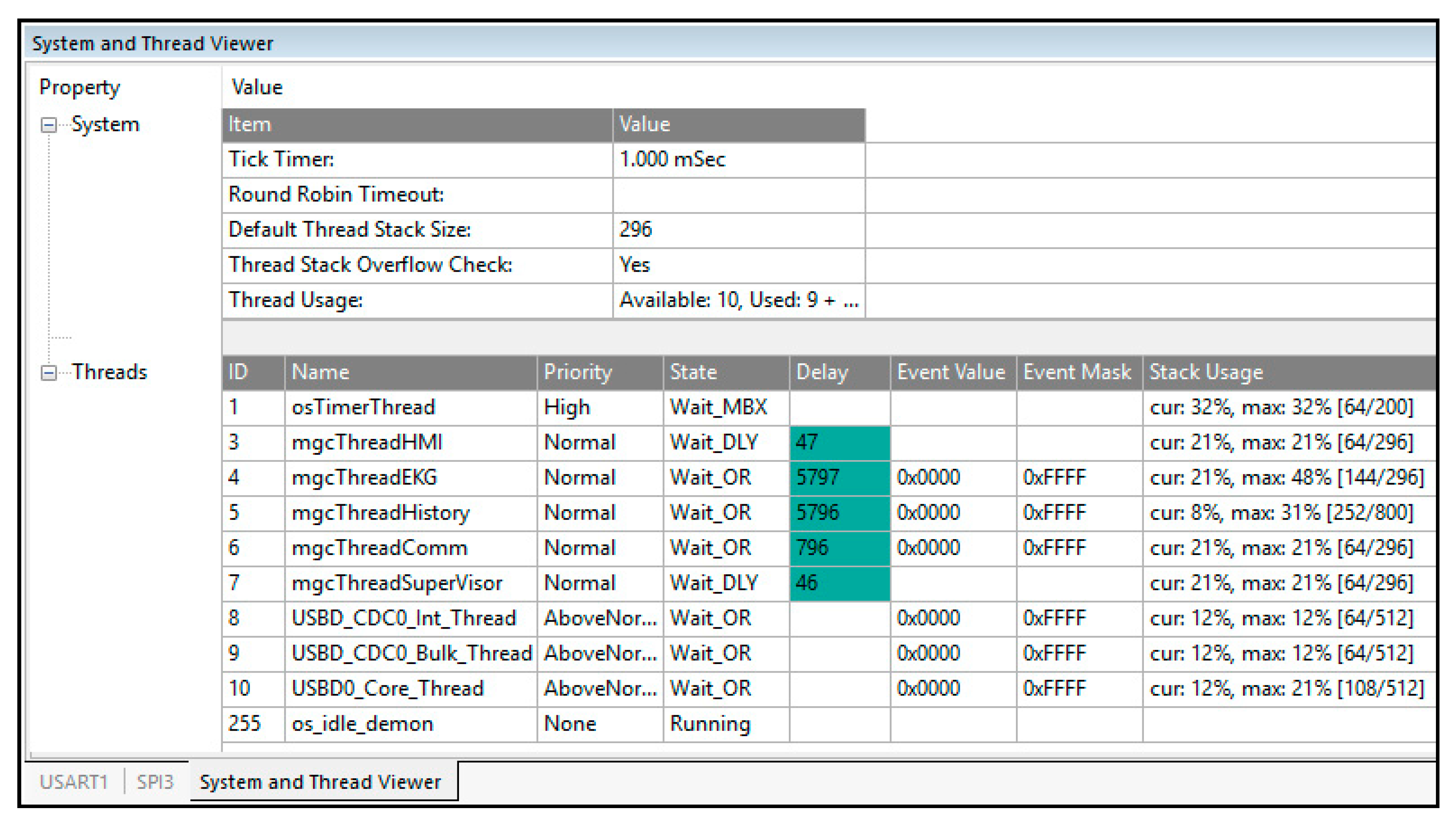
From the perspective of the RTOS configuration, all tasks of the application are executed, as shown in Figure 5. The design environment also provides solid support for memory viewing, variable analysis (symbols, stack, serial communication, etc.), event viewing, and tracking and modifying peripheral registers; these processes enable logical testing, both through simulation and by forcing values. Using this support, in the design and debug state, important code was written to test the functionality of some procedures under laboratory conditions.
The SPI interface between the microcontroller and the ADAS1000 circuit performs data exchange in both directions simultaneously, supporting a single point of master communication with multiple slave devices. The clock frequency determines the data transfer rate. The clock speed is normally between 100 KHz and 10 MHz; this implies that the data rate ranges from 1 to 20 Mbps. Although the primary read function of the ADAS1000 circuit is represented by ECG data, the reading of all configuration registers is also enabled. In order to read a register, one must first send a read command to the device; the read command must contain the register-specific address. If the Telecare-ECG Monitor mobile device is already in the data transfer mode, the command for reading the registers can be sent between frames by issuing a command during the last word of the frame data. The data transferred during the next word are the data read from that specific register. To return to the previous mode, we must reactivate the framing by issuing a frame header register (address 0x40). In order to initialize the device to capture the ECG and transmit the relevant data, the steps described below should be followed. The first writing configures the CMREFCTL register for CM = WCT = (LA + LL + RA) / 3, with the RLD being enabled on the RLD_OUT electrode; also, the protection amplifier is validated. The second writing configures the FRMCTL register to obtain seven words per frame. This frame consists of header, three ECG words, heart rate, breathing magnitude, and lead-off. The frame is configured to always transmit, regardless of status. Thus, the device is set to analog mode with a 2 kHz transfer rate. The third writing addresses the ECGCTL register, allowing all channels to have a gain of 1.4, a low noise mode, and a differential input that configures the device for analog mode. Through the fourth writing in the ADAS1000 circuit register, the command is issued to begin transmitting the bits to the SDO pin; the bits correspond to the data obtained from the conversion of the ECG. The final step consists of issuing SCLK cycles to read the converted data to the configured data rate (2 kHz). For proper functioning, when using three electrodes and when the respiration module is activated, the ADAS1000 ECG circuit will need a total current consumption of 17.3 mA. The low-power Bluetooth module will consume only 10.5 mA in transmission mode and 3.5 µA in system idle mode.
Table 1 shows the structure of an ECG file and the operations of managing ECG files performed by the mgcThreadHistory task at the initiation of the mgcThreadComm task (Figure 4b). Saving the ECG on the SD memory card as an individual file is done by the mgcThreadHistory task when receiving an event from the mgcThreadEKG task. In the designing and validation stages of the microcontroller software, it was necessary to configure various tests and write code for the extra MODBUS functions used to trigger the launch of complex test operations.
The main tests for the mobile Telecare-ECG application and their tasks are presented below, with emphasis on the operations and tasks involved. After the RTOS task setup stage, a user interface was developed to handle the event generated by the action of the user button, using the wake up key on the MCBST32C kit (mgcThreadHMI task). In addition to the user interface, the LEDs were turned ON, and sound was generated using the buzzer (mgcThreadHMI task). The mgcThreadComm task (Figure 4b) is responsible for the implementation of the communication components, namely the USB and VitualComm (PC) communication using Modbus Poll and Bluetooth communication with HC 06 and GSM/SMS communication via the SIM800 circuit (SMS was tested with a smartphone). In addition to these actions, the DEBUG module was activated; using this module, the mgcThreadComm task can simulate all MODBUS messages of the other tasks.
In the case of the SIM800C circuit, enabling operation can be performed by resetting the PWRKEY pin for at least one second, after which it is released. This pin is already connected to VBAT in the internal mode, so it is not necessary to connect it. The SIM800C circuit has two power-saving modes: a minimum functionality mode and a sleep mode. The AT “AT + CSCLK = 1” command can be used to set the SIM800C in sleep mode, and the AT “AT + CFUN = <fun>” command can be used to set the SIM800C to minimum functionality. When SIM800C is in the sleep mode and minimum functionality mode, the power consumption of the module is minimal. Pin 42 of the circuit was used to indicate the operating status of the SIM800 module. When the module is switched on, pin 42’s output is 1 (on), and when the module is off, the output is 0 (off).
For hardware/software debugging, the following have been tested: the reading/writing of the ADAS100 registers (mgcThreadEKG enabled by the mgcThreadComm task); the ECG read (mgcThreadEKG task launched by either the mgcThreadHMI or mgcThreadComm tasks as a result of an extra function); the reading of the files located on the SD card (the mgcThreadHistory task at the initiation of the mgcThreadComm task), the watchdog timer (WDT) circuit; and the temperature sensor, the accelerometer, and the accumulator charging and supervision circuit operations (mgcThreadSuperVisor task). For real-time testing, MODBUS (TCR-MD) functions have often been used in the past. Thus, the extra Modbus 42 function launches the execution of an ECG (it activates the EVT_EXECUTED_BY _EKG_TO_COMM event to announce the communication task that is to be executed) and afterwards performs the ECG. If the ECG is properly executed, it sends an EVT_EXE_EKG_ LOGG_NEW_JOB event for the history task to save the ECG as an ASCII file on the SD card. Compared to similar projects in the literature [8], the Telecare-ECG Monitoring device saves the ECG data on a microSD memory card, where it can be retrieved later if there is no functional communication when the ECG is performed. Using the STM32F107 microcontroller adds extra performance to the system because, besides its flexibility, it also ensures low power consumption.
In the case of the Telecare-ECG Monitor (Figure 6), heart rate storage and transmission of the data to a supervisor are the main objectives of the system. Therefore, the data collected by the proposed Telecare-ECG Monitor embedded system designed for out-of-hospital cardiac patients satisfy both the accuracy and reliability requirements imposed by the relevant standards. To accomplish Telecare services, IoT embedded systems and sensors that include ECG and RFID readers, accelerometers, GPS or thermometers must operate in a non-intrusive mode for out-of-hospital cardiac patients and record data in a real-time and reliable manner.
Sensor standards are necessary because such devices are already prevalent today and will become even more necessary in the field of IoT devices and applications. Using different protocols and formats, sensors are manufactured by a variety of companies based on standards and large-scale IoT integration. Table 2 and Table 3 present the data corresponding to the integrated circuits used to create the Telecare-ECG mobile device through medical information systems in the context of the Internet of Medical Things. In order to be a competitive monitoring embedded system, the Telecare-ECG mobile device must record, store, and transmit the ECG to the server.
4.2. Methods for Design, Validation and Testing
During an ECG measurement, the out-of-hospital cardiac patient might move quickly or tilt slowly; this movement will depend on the threshold and the time values configured for this type of event. Motion can be used to simply alert the microcontroller when an ECG measurement is performed. When the acceleration exceeds the set threshold, the corresponding signal is activated. The MMA8452Q integrated circuit can be configured with scaling at ± 2 g / ± 4 g / ± 8 g, with upstream filtered data, as well as with non-filtered data available in real time. The functions and timing of the interrupt pins, INT1 and INT2, are programmable through the I2C interface.
For the laboratory tests, the box shown in Figure 7 was created with a 3D printer, incorporating both the PCB and the accumulator. The ECG portable device has two working modes:
- ECG selection mode: The operator selects the state mode circularly by pressing the user key for periods of less than three seconds (see also the front view in Figure 7).
- ECG execution mode: The operator launches the pre-selected work mode.
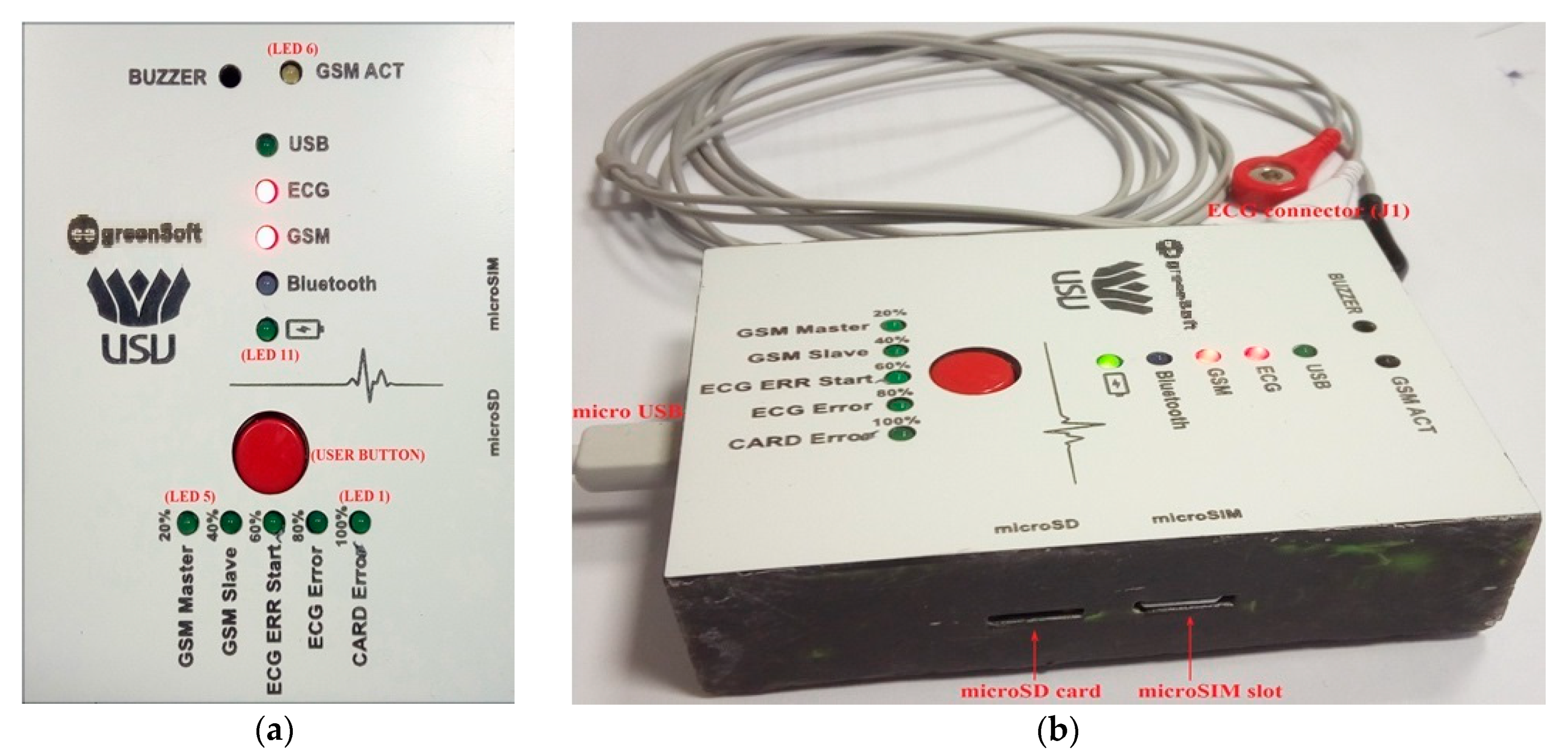
From a software point of view, the connection of the ADAS1000 basic circuit to SPI and the generation of self-test signals were validated. The human operator interface includes 11 LEDs and a buzzer inside the 3D printer electronic box (Figure 7). Eight of the proposed LEDs are controlled by the software, and three of them are connected by specialized internal circuits. The LEDs managed by the human operator are as follows:
- LED 1: 100% (in ECG selection mode)\CARD Error: file system error (in ECG execution mode);
- LED 2: 80% (in ECG selection mode)\ECG Error: error associated with communication related to ECG circuit (in ECG execution mode);
- LED 3: 60% (in ECG selection mode)\ECG ERR Start: incorrect patient position before ECG start (in ECG execution mode);
- LED 4: 40% (in ECG selection mode)\GSM SLAVE: indicates the selection or operation mode for slave GSM communications;
- LED 5: 20% (in ECG selection mode)\GSM Master: indicates the selection or operation mode for master GSM communications;
- LED 6: GSM ACT indicates the connection to a GSM network;
- LED 7: indicate USB selection or operating mode;
- LED 8: indicate ECG selection or operating mode;
- LED 9: indicates the power supply of the GSM;
- LED 10: Bluetooth indicates selection or operating mode of BLE (Bluetooth) or GSM Master, together with the GSM Master LED and the GSM Slave together with the GSM Slave LED.
The following three LEDs are managed by specialized circuits:
- LED 11: indicates the status of the accumulator (disconnected: blinks, charging: ON, charged: OFF).
- Optionally, there may be an LED that indicates the USB connection to the micro USB connector (located close to the USB port).
Digital input managed by the human operator:
- The device is provided with a user button to select the execution mode (the central red button illustrated in Figure 7). Pressing and releasing this button will turn the buzzer on or off.
The electronic box is also equipped with two slots (located on the right side, as shown in Figure 7b): one for inserting the microSIM card and one for inserting a microSD memory card, with a storage capacity between 2 and 8 GB. The micro USB connector (the left cable in Figure 7b) enables the connection to a USB port on a compatible PC for local ECG file management. To reset the device in the case of unpredictable situations and to connect the ECG cable, two slots are provided on the left side of the mobile Telecare-ECG device (Figure 7b illustrates the three electrodes that are connected to the mobile ECG device). A temperature sensor is predisposed on the back side of the device, and inside the device there is an ON/OFF switch that enables the accumulator to be removed. This device is provided with a special ECG cable for signal acquisition to perform the ECG; the cable is inserted into the J1 connector, as shown in Figure 6b. The LEDs can be in four states, ON, OFF, Low Frequency Flashing (IIFMI), or High Frequency Flashing (IIFMA). The buzzer generates a sound with a frequency of 4 KHz and can be in one of the following states: OFF, permanently ON, intermittent ON/OFF for one second (ON 1 second/OFF 1 second) (POI1s), and intermittent ON/OFF for three seconds (POI3s).
The electrodes are placed by the patient himself in the pectoral area. Since this device is intended for the monitoring of patients with chronic conditions, the specialist doctor will instruct the monitored patient on the correct use of the device. The system will warn the user if one or more electrodes do not receive a signal or if other errors occur in the operation of the device. Additionally, LED 3 indicates if the patient is in a bad position for performing the ECG.
If the device is in execution mode and the operator presses the user key, it switches the device to the ECG selection mode located in the same working mode (which can be selected from the ECG selection mode by pressing the key for more than 3 seconds to enter ECG execution mode and then pressing the key for less than 3 seconds to pass the device into ECG selection mode). By pressing the key for less than 3 seconds, five ECG selection modes can be accessed (un-referenced LEDs are in the OFF state):
- ECG selection mode: The ECG LED is ON, and the five horizontal LEDs indicate the accumulator charge status (only in this state);
- USB selection mode: The USB LED is ON;
- BLE selection mode: The Bluetooth LED is ON;
- GSM MASTER selection mode: The Bluetooth LED is in the IIFMI state (blinks at a low frequency), and the GSM LED is ON;
- GSM SLAVE selection mode: The Bluetooth LED is in the IIFMI state, and the GSM LED is ON;
- EXIT selection mode: All operator LEDs are OFF.
By pressing the user key for more than three seconds, five execution modes can be selected:
- ECG execution mode: The ECG LED is in the IIFMA state (blinks at a high frequency);
- USB execution mode: The USB LED is in the IIFMA state;
- BLE execution mode: The Bluetooth LED is in the IIFMA state;
- GSM MASTER execution mode: The Bluetooth and GSM LEDs are in the IIFMA state;
- GSM SLAVE execution mode: The Bluetooth and GSM LEDs are in the IIFMA state;
- EXIT execution mode: The Telecare-ECG device enters into a low-power state.
When starting the Telecare-ECG Monitor embedded device, the following operations can be performed:
- The operator checks for the microSD card, so no ECGs can be made without the microSD card. The internal accumulator switch is assumed to be in the ON position. Users can omit its presence if calibration, debugging, or maintenance work is done.
- Press the user key until the LED test starts. This test will switch the LEDs to the IIFMA state for 2 seconds each; after testing the 8 LEDs, the system switches to the ECG selection mode (the ECG LED will be ON).
- During the test, the buzzer will indicate an ON state by emitting a 4 kHz sound.
This sub-section describes the ECG execution modes. First, the out-of-hospital cardiac patient must ensure that his/her name, sex, and birth date are set in the ECG device. These data will be found in the header of the ECG file, as can be seen in Table 4 (if the device is used by more than one person, this operation is mandatory before performing an ECG). In order to view and analyze the results, the Telecare-ECG Monitor application installed on a phone or a PC can be used.
After connecting the electrodes, the out-of-hospital cardiac patient sets the device to the ECG selection mode, sits in a horizontal position with the device on his/her chest, and presses the red user key for more than 3 seconds (Figure 7). If the ECG recording begins (the ECG execution mode is started), the buzzer is in the POI1s state (flashes ON/OFF for one second). If an error occurs (the device does not have a start condition due to an incorrect position, the ECG acquisition circuit not working properly, or the file system being incorrect (for example, no micro SD card)), the buzzer switches to the POI3s state. When the user presses the button for less than three seconds, the device is returned to the ECG selection mode; in this case, the buzzer does not emit an acoustic message, and the error indicator LED goes OFF.
If an ECG file has been created on the microSD, the device goes into the GSM MASTER mode and sends a Modbus message to the server. Thus, we have the following situations:
- The device issues an SMS every five minutes until either it exits from this execution mode or the server responds with the sequence 5F100090001CCC93, at which point the device goes into GSM SLAVE execution mode and waits for commands from the server (for example, to read the file). The name of the transmitted file is strictly related to the creation date (M0:\YearMonthDay\HourMinuteSecond.txt).
- When attempting to emit an SMS, the buzzer is set in the POI10_15s state, and when it receives an SMS, the buzzer goes into the POI0_5s state.
The USB execution mode will be described below. To enter this state, the USB selection mode must be accessed, and the patient must press the user key for more than three seconds. If the USB IIFMA LED indicates USB mode, the device is a SLAVE with address 95 (0x5F) and executes Modbus commands using a Virtual Comm (on USB). Pressing the key causes a return to the USB selection mode. The BLE execution mode works as follows. The BLE selection mode is selected via the provided interface, and the key is pressed for more than three seconds. If the Bluetooth LED is in the IIFMA state, the BLE execution mode has been activated. Thus, the device is a SLAVE with address 95 and executes Modbus commands using a Virtual Comm. Pressing the user key will return to the BLE selection mode. For the GSM MASTER mode, the GSM MASTER selection mode is selected with the Bluetooth LED in the IIFMI state and the GSM MASTER LED on.
For the GSM SLAVE mode, the GSM SLAVE selection mode is selected with the Bluetooth LED in the IIFMI state and the GSM SLAVE LED on. The user key is pressed for more than three seconds so that if the Bluetooth LED is in the IIFMA, and the GSM SLAVE is in the IIFMA state, the GSM SLAVE mode can be entered with address 95 (0x5F), which executes the Modbus commands. There are two modes: The first one is ASCII, where the registers have ASCII values and must be converted into ASCII HEX and vice versa (only the header and CRC). The second mode is RTU, where ASCII HEX must be converted into a MODBUS RTU message. Pressing the user key causes a return to the GSM MASTER selection mode.
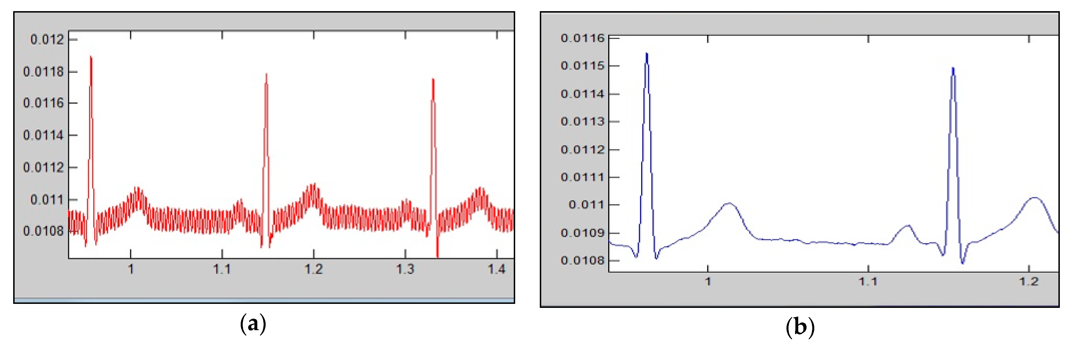
Figure 8 plots part of the ECG signal collected from a patient using the user’s desktop interface.
The Telecare-ECG Monitor Gateway application transfers the ECG data from the mobile device, saves them into an XML file specific to the Telecare-ECG Monitor system, and transfers these files to the server via the FTP protocol. In order to test and validate the Telecare-ECG mobile device, we have used the Qt development environment, which facilitated the development of platform-independent desktop and mobile applications. By pressing the red user button on the Telecare-ECG Monitor for 3 seconds, an ECG measurement will be launched for 10 seconds. The data specific to the ECG recording are automatically saved on the microSD card (for later or manual reading, by attaching the micro SD to a compatible PC). Successively, there is the attempt to notify a server to retrieve and distribute the new ECG data (the header enables the identification of the device and the out-of-hospital cardiac patient). To ensure the Telecare-ECG Monitor’s compatibility, an application called the Telecare-ECG Monitor Gateway was developed. This application also allows the aforementioned calibration, testing, and debugging tasks for the mobile device. When testing the Telecare ECG monitoring device, we used the simultaneous acquisition of signals from this device and a three-channel portable ECG electrocardiograph that has already been developed. The resulting signals were compared, with no significant differences recorded. The Telecare ECG monitoring device will follow the necessary steps for certification by the Romanian Bureau of Legal Metrology and for approval by the Ministry of Health.
5. Discussion
This paper presents a practical use case to demonstrate that the developed Telecare-ECG IoT device can be used in different environments, such as health care facilities, home care (covering all the places where patients live, including those where the equipment can be operated by non-specialist users, with limited power supply sources), or special environments (such as industrial areas, where an out-of-hospital cardiac patient operates daily, that may also have high levels of electromagnetic disturbance). An expected outcome of the Telecare-ECG Monitoring Gateway application is its impact on health [22]. The correct estimation of clinical symptoms, such as via ECG signals, is vital. These innovative approaches will have a direct clinical impact because they will be used to monitor and diagnose out-of-hospital cardiac patients and to intervene remotely and quickly.
The practical utility of this device comes from its integration in a platform (GreenCardio©) that provides remote monitoring and diagnostic services for patients with heart disease. GreenCardio© is a telemedicine application, which, together with the ECG device, allows the remote monitoring (at home, in the office, or in the community) of patients, and offers the possibility for the remote transmission of specialized medical recommendations. The GreenCardio© telemedicine application has already been implemented, and further details can be accessed at http://greencardio.ro/.
In order to evaluate the Telecare-ECG Monitoring IoT device, we have created a test infrastructure based on the Telecare-ECG Monitor Gateway application, the ECG sensor, and the IEC60601 standard. Based on the system evaluation process and performance tests validated by a biomedical engineer, the proposed embedded system has had the following applications validated in different medical and environment scenarios:
- ECG acquisition on multiple channels.
- Real-time signal preprocessing and the real-time assessment of the signal/noise ratio for different frequency bands in order to determine the nature of the noise.
- Dynamic selection of the optimal noise extractor and of the QRS complex detector.
- An alarm in the case of a critical situations and data storage in the absence of communication.
- Secure data interpretation for diagnostic assistance.
- The transmission of synthetic data to a high-level module to detect and classify various pathologies using pattern recognition methods.
The challenge of designing a Telecare-ECG Monitor embedded system for out-of-hospital cardiac patients was achieved through compliance with the strict rules imposed in the field of medical devices. This compliance is not always easy to achieve because significant practical experience is required. As a result, the authors demonstrated the potential of the technologies used by designing a competitive Telecare-ECG Monitoring device in order to meet the needs and requirements demanded by the market while minimizing the design time through rapid prototyping and testing. Therefore, the data collected by the proposed embedded system satisfy both the accuracy and reliability requirements. The telecare-ECG Monitor embedded device can be optimized by improving its software, energy consumption, and overall IoT system performance. Designing tools for the remote and real-time monitoring of out-of-hospital cardiac patients is a significant challenge in an IoT context ([23,24]). The MCBSTM32 kit and Keil development platform were essential in facilitating our research activities in designing, prototyping, and testing the mobile tele-electrocardiograph within the Telecare-ECG Monitor system for the monitoring and diagnosis of patients. If the predefined critical elements appear, the specialized Telecare-ECG Monitoring server can notify the dispatcher about these events. Consequently, it is important that research projects written and implemented using C code are well documented, flexible, and parameterized.
An alternative solution for this project could be the nMPRA (Multi Pipeline Register Architecture) processor implementation [25]. Using this processor with functions implemented in the hardware would add extra performance to the system, as well as superior energy efficiency.
6. Conclusions
For the Telecare-ECG Monitor embedded system, the use of sensors enables and sustains its IoT purpose by retrieving sensor data, tasking sensors, and subscribing to and receiving alerts regarding the ECG type. Moreover, the long period of ECG monitoring cannot be triggered manually, and real-time support technologies are necessary to automatically identify an out-of-hospital cardiac patient and decide if that user requires immediate emergency intervention or professional attention. The presented distributed embedded system has great advantages in the remote monitoring and diagnosis of patients with cardiac pathologies, allowing ECG investigation capabilities to be extended to patients who cannot benefit from specialized medical services in the cardiology area (e.g., patients in rural areas, patients difficult to transport, or cardiac patients that live in areas with low population density). The importance of sensors in the Internet of Medical Things domain, and the entities with which they interact, is mainly determined by tagging and monitoring out-of-hospital cardiac patients and by enabling the sensors to be aware of the environment around them.
7. Patents
The Telecare-ECG Monitor concept presented in this paper is based on an A/00701 patent application, submitted on 20.09.2018 to OSIM, Bucharest, Romania, under the name “System for acquiring and processing of physiological parameters”.
Author Contributions
Conceptualization, A.B., V.G.G., I.Z. and A.-I.P.; Software, V.G.G.; data curation, I.Z., A.-I.P. and N.I.; writing—original draft preparation, I.Z. and V.G.G.; writing—review and editing, I.Z., N.I., and V.G.G.; Supervision, V.G.G. and A.B.; project administration, V.G.G.; funding acquisition V.G.G. and A.B. All authors have read and agreed to the published version of the manuscript.
Funding
This work is supported by the project ANTREPRENORDOC, in the framework of Human Resources Development Operational Programme 2014-2020, financed from the European Social Fund under the contract number 36355/23.05.2019 HRD OP /380/6/13—SMIS Code: 123847.
Acknowledgments
The authors would like to thank the editors and anonymous reviewers for reviewing our manuscript.
Conflicts of Interest
The authors declare no conflict of interest.
References
- Zimmer, V.; Sun, J. Embedded Firmware Solutions: Development Best Practices for the Internet of Things, 1st ed.; APress: Berlin/Heidelberg, Germany, 2015; pp. 16–17. ISBN 10 1484200713. [Google Scholar]
- Smithamol, M.B.; Rajeswari, S. Hybrid Solution for Privacy-Preserving Access Control for Healthcare Data. Adv. Electr. Comput. Eng. 2017, 17, 31–38. [Google Scholar] [CrossRef]
- Madisetti, V.; Bahga, A. Internet of Things (A Hands-on-Approach); Springer: New York, NY, USA, 2014; pp. 20–46. ISBN1 10 0996025510. ISBN2 13 978-0996025515. [Google Scholar]
- Zagan, I.; Găitan, V.G.; Iuga, N.; Brezulianu, A. m-GreenCARDIO embedded system designed for out-of-hospital cardiac patients. In Proceedings of the 2018 International Conference on Development and Application Systems (DAS), Suceava, Romania, 24–26 May 2018; pp. 11–17. [Google Scholar] [CrossRef]
- Ungurean, I.; Brezulianu, A. An Internet of Things Framework for Remote Monitoring of the HealthCare Parameters. Adv. Electr. Comput. Eng. 2017, 17, 11–16. [Google Scholar] [CrossRef]
- Gouaux, F.; Simon-Chautemps, L.; Fayn, J.; Adami, S.; Arzi, M.; Assanelli, D.; Forlini, M.C.; Malossi, C.; Martinez, A.; Placideet, J.; et al. Ambient intelligence and pervasive systems for the monitoring of citizens at cardiac risk: New solutions from the EPI-MEDICS project. Comput. Cardiol. 2002, 289–292. [Google Scholar] [CrossRef] [Green Version]
- Sardana, P.; Kalra, M.; Sardana, A. Design, Fabrication, and Testing of an Internet Connected Intravenous Drip Monitoring Device. J. Sens. Actuator Netw. 2019, 8, 2. [Google Scholar] [CrossRef] [Green Version]
- El Mimouni, E.H.; Karim, M. A MicroBlaze-based Multiprocessor System on Chip for real-time cardiac monitoring. In Proceedings of the 2014 International Conference on Multimedia Computing and Systems (ICMCS), Marrakech, Morocco, 14–16 April 2014; pp. 331–336. [Google Scholar] [CrossRef]
- PhysioNet: MIT-BIH Arrhythmia Database. Available online: https://physionet.org/physiobank/database/mitdb/ (accessed on 20 March 2017).
- Ukil, A.; Bandyoapdhyay, S.; Puri, C.; Pal, A. IoT Healthcare Analytics: The Importance of Anomaly Detection. In Proceedings of the IEEE 30th International Conference on Advanced Information Networking and Applications (AINA), Crans-Montana, Switzerland, 23–25 March 2016; pp. 994–997. [Google Scholar] [CrossRef]
- Park, J.; Lee, J.; Ryu, J.; Shin, H.; Heu, S.; Kang, K. Evaluating QoS of a Wireless System for Real-Time Cardiac Monitoring. In Proceedings of the IEEE 27th International Conference on Advanced Information Networking and Applications (AINA), Barcelona, Spain, 25–28 March 2013; pp. 1105–1112. [Google Scholar] [CrossRef]
- Al-Dulaimi, J.; Cosmas, J.; Abbod, M. Smart Health and Safety Equipment Monitoring System for Distributed Workplaces. Computers 2019, 8, 82. [Google Scholar] [CrossRef] [Green Version]
- Sánchez, L.; Lanza, J.; Santana, J.R.; Agarwal, R.; Raverdy, P.G.; Elsaleh, T.; Fathy, Y.; Jeong, S.; Dadoukis, A.; Korakis, T.; et al. Federation of Internet of Things Testbeds for the Realization of a Semantically-Enabled Multi-Domain Data Marketplace. Sensors 2018, 18, 3375. [Google Scholar] [CrossRef] [PubMed] [Green Version]
- Yang, Z.; Zhou, Q.; Lei, L.; Zheng, K.; Xiang, W. An IoT-cloud Based Wearable ECG Monitoring System for Smart Healthcare. J. Med Syst. 2016, 40, 286. [Google Scholar] [CrossRef] [PubMed]
- ARM®RTX™. Real-Time Operating System, A Cortex-M Optimized RTOS That Simplifies Embedded Programming; ARM: Cambridge, UK, 2013. [Google Scholar]
- Yiu, J. The Definitive Guide to ARM® Cortex®-M0 and Cortex-M0+ Processors, 2nd ed.; Academic Press: Cambridge, MA, USA, 2015; pp. 57–64. ISBN 10 0128032774. [Google Scholar]
- Zagan, I.; Găitan, V.G.; Petrariu, A.-I.; Brezulianu, A. Healthcare IoT m-GreenCARDIO Remote Cardiac Monitoring System—Concept, Theory of Operation and Implementation. Adv. Electr. Comput. Eng. 2017, 17, 23–30. [Google Scholar] [CrossRef]
- Majumder, S.; Aghayi, E.; Noferesti, M.; Memarzadeh-Tehran, H.; Mondal, T.; Pang, Z.; Deen, M. Smart Homes for Elderly Healthcare—Recent Advances and Research Challenges. Sensors 2017, 17, 2496. [Google Scholar] [CrossRef] [PubMed] [Green Version]
- Zhu, Y. Embedded Systems with ARM Cortex-M3 Microcontrollers in Assembly Language and C; E-Man Press LLC: Ballston Spa, NY, USA, 2014; pp. 457–464. ISBN1 10 0982692625. ISBN2 13 978-0982692622. [Google Scholar]
- SIM800C. Available online: SIM800C_Hardware_Design_V1.02.pdf (accessed on 16 April 2018).
- MMA8452Q. Available online: https://www.nxp.com/docs/en/data-sheet/MMA8452Q.pdf (accessed on 16 April 2018).
- ADAS1000. Available online: http://www.analog.com/media/en/technical-documentation/data-sheets/ADAS1000_1000-1_1000-2.pdf (accessed on 16 April 2018).
- Choi, Y.; Kang, H.; Lee, I. Scalable and Secure Internet of Things Connectivity. Electronics 2019, 8, 752. [Google Scholar] [CrossRef] [Green Version]
- Saman, K.; Ali, D.M.; Ghaznavi-Ghoushchi, M.B. Low-complexity and differential power analysis (DPA)-resistant two-folded power-aware Rivest–Shamir–Adleman (RSA) security schema implementation for IoT-connected devices. Iet Comput. Digit. Tech. 2018, 12, 279–288. [Google Scholar] [CrossRef]
- Zagan, I.; Găitan, V.G. Hardware RTOS: Custom Scheduler Implementation Based on Multiple Pipeline Registers and MIPS32 Architecture. Electronics 2019, 8, 211. [Google Scholar] [CrossRef] [Green Version]
Figure 1.
Telecare-ECG Monitor architecture designed for out-of-hospital cardiac patients.

Figure 2.
The block diagram of the Telecare-ECG Monitor module; GPIO—General-Purpose Input/Output; JTAG—Joint Test Action Group Interface; GPRS—General Packet Radio Services.
Figure 2.
The block diagram of the Telecare-ECG Monitor module; GPIO—General-Purpose Input/Output; JTAG—Joint Test Action Group Interface; GPRS—General Packet Radio Services.

Figure 3.
(a) Using the MCBSTM32 and ADAS1000 development kits to perform a trial version of the Telecare-ECG Monitor project [17]; (b) testing under the laboratory conditions of the Telecare-ECG Monitoring device [4]; 1—STM32F107 Microcontroller Development Board; 2—ADAS1000 module; 3—SIM800C-BT module and antenna; 4—Unique ID module DS2411; 5—Accelerometer and temperature sensor; 6—Accumulator charger; 7— Bluetooth, 8—JTAG Interface.

Figure 4.
(a) Application structure for the Telecare-ECG device in Keil uVision5 [4]; (b) the fundamental machine states for Telecare-ECG Monitoring device tasks execution [17].

Figure 5.
The installed application tasks seen in the uVision5 DEBUG mode [17] (the application is already running on the STM32F107 microcontroller).
Figure 5.
The installed application tasks seen in the uVision5 DEBUG mode [17] (the application is already running on the STM32F107 microcontroller).

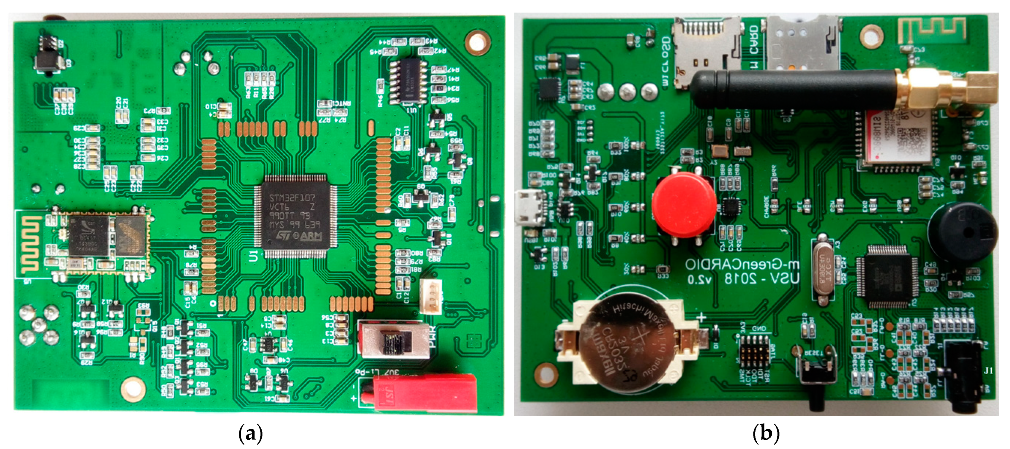
Figure 6.
(a) TOP view and (b) BOTTOM view of the PCB for the Telecare-ECG Monitor mobile device.

Figure 7.
Telecare-ECG Monitor mobile device (a) top view; (b) microSD and microSIM slots, electrodes for physiological parameters capture, and USB cable (left side) for connection to a personal computer.
Figure 7.
Telecare-ECG Monitor mobile device (a) top view; (b) microSD and microSIM slots, electrodes for physiological parameters capture, and USB cable (left side) for connection to a personal computer.

Figure 8.
(a) The ECG unfiltered signal using the user’s desktop interface; (b) The ECG filtered signal using the Telecare-ECG Monitoring device.
Figure 8.
(a) The ECG unfiltered signal using the user’s desktop interface; (b) The ECG filtered signal using the Telecare-ECG Monitoring device.


Table 1.
Header and structure of an ASCII ECG file with 5000 records for three electrodes.
| Field Definition | Values (hexadecimal) |
|---|---|
| Device address | 5F |
| The write function (16) in MODBUS registers | 10 |
| Start address (means new ECG file) | 00 90 |
| Counter registers | 00 1C |
| Counter bytes | 38 |
| Out-of-hospital cardiac patient phone number | +3960144676375 |
| Telecare-ECG Monitoring device code | 018417EA190000B0 |
| New (current) file name | M0:\20180920\16M54S29.txt |
| CRC Modbus | 6F82 |
Table 2.
Characteristics of the processing and communication devices used in the Telecare-ECG medical information system.
Table 2.
Characteristics of the processing and communication devices used in the Telecare-ECG medical information system.
| Microcontroller: STM32F107VCT6TR | Bluetooth Module: HC-06 | Unique ID Module: DS2411 | GSM Transmission Module: SIM800C [20] |
|---|---|---|---|
| ARM 32-bit Cortex-M3; Maximum speed: 72 MHz; 256 kB flash memory; 64 kB SRAM; 16 ADC channels with 12 bits; Interfaces: SPI, I2C, I2S, UART, USB; Up to 80 GPIO ports; Supply voltage between 3 and 3.6 V; The possibility to change the microcontroller by using an adaptation socket. | Sensitivity to data transmission: −80 dBm; Output power configurable between −4 dBm and +6 dBm; Transfer speed: 2 Mbps; 9 Mb FLASH internal memory; Current consumed in transmission mode: 8 mA; Frequency of operation: 2.4 GHz; Standard port: HCI (UART or USB); Supply voltage between 3.1 and 4.2 V. | Unique internal code of 64 b, laser engraved; Supply voltage between 1.5 V and 5.25 V; Communication speed up to 15.4 kbps; Current consumption: 100 µA. | Quad-Band (GSM850, EGSM900, DCS1800, PCS1900); 24 Mb FLASH internal memory; 32 Mb RAM memory; Supply voltage between 3.4 and 4.4 V; Current consumption in idle mode of 13.8 mA; Power consumption in call mode of up to 413 mA; Power consumption in sleep mode of a maximum 1.5 mA. |
Table 3.
Sensors and auxiliary integrated circuits featured within the Telecare-ECG Monitoring device in the context of the Internet of Medical Things.
Table 3.
Sensors and auxiliary integrated circuits featured within the Telecare-ECG Monitoring device in the context of the Internet of Medical Things.
| Accelerometer on 3 Axes: MMA8452QT [21] | Battery Charger: BQ24296M | ECG data Acquisition Circuit: ADAS1000 [22] | Temperature Sensor: TMP100 |
|---|---|---|---|
| Supply voltage between 1.95 and 3.6 V; 12 bit and 8 bit digital converter; Current consumption between 6 and 165 µA; Output Data Rates from 1.56 to 800 Hz; I2C digital interface. | Communication with microcontroller via I2C interface; Maximum charging current of 3 A; Input voltage between 3.9 and 6.2 V; Possibility to limit the charging current; Thermal charging protection of the battery; Overvoltage protection of the battery; LED indicator for charging status or missing battery. | SPI communication interface; Acquisition of ECG signals using 3 or 5 electrodes; Possibility of parallel connection for reading vital signals with over 10 electrodes; Supply voltage between 3.15 and 5.5 V; Maximum current consumption: 975 µA. | I2C communication interface; User selectable resolution: 9 to 12 bits; Typical accuracy of ±1 °C; Measurement of temperatures between −55 and +125 °C; Supply voltage between 2.7 and 5.5 V; Maximum current consumption: 150 µA. |
Table 4.
Header and data for ECG records stored in the ECG file.
| ECG Capture Settings | ECG Capture Information’s | ECG Records |
|---|---|---|
| File name: M0:\20180919\12M28S36.txt Number of samples = (500 × 3 × 2) × 10 = 30.000 Time period for ECG capture = 10 seconds Sampling speed = 500 samples per second Source = Three electrodes for ECG | Record name: ECG: 19:09:2018-12:28:36 Telecare-ECG Monitoring device code: 018417EA190000B0 Patient name: Carl Berry The patient’s sex: male Date of birth: 29:11:1989 Temperature: degrees Celsius: 28 Note: No note | 0000 FE60 FD20 FEC0 0001 FE78 FE45 FFCD 0002 057D 47E0 4263 0003 21D7 29B0 07D9 0004 5095 1B7A CAE5 0005 855D 9A92 1535 |
© 2020 by the authors. Licensee MDPI, Basel, Switzerland. This article is an open access article distributed under the terms and conditions of the Creative Commons Attribution (CC BY) license (http://creativecommons.org/licenses/by/4.0/).
Share and Cite
MDPI and ACS Style
Zagan, I.; Găitan, V.G.; Petrariu, A.-I.; Iuga, N.; Brezulianu, A. Design, Fabrication, and Testing of an IoT Healthcare Cardiac Monitoring Device. Computers 2020, 9, 15. https://0-doi-org.brum.beds.ac.uk/10.3390/computers9010015
AMA Style
Zagan I, Găitan VG, Petrariu A-I, Iuga N, Brezulianu A. Design, Fabrication, and Testing of an IoT Healthcare Cardiac Monitoring Device. Computers. 2020; 9(1):15. https://0-doi-org.brum.beds.ac.uk/10.3390/computers9010015
Chicago/Turabian StyleZagan, Ionel, Vasile Gheorghiță Găitan, Adrian-Ioan Petrariu, Nicolai Iuga, and Adrian Brezulianu. 2020. "Design, Fabrication, and Testing of an IoT Healthcare Cardiac Monitoring Device" Computers 9, no. 1: 15. https://0-doi-org.brum.beds.ac.uk/10.3390/computers9010015
Note that from the first issue of 2016, this journal uses article numbers instead of page numbers. See further details here.