Article

ARIA—A VUV Beamline for EuPRAXIA@SPARC_LAB

1
INFN-Laboratori Nazionali di Frascati, Via E. Fermi 54, 00044 Frascati, Italy
2
CNR—Istituto Struttura della Materia and Elettra-Sincrotrone Trieste, Basovizza Area Science Park, 34149 Trieste, Italy
3
Elettra-Sincrotrone Trieste, Basovizza Area Science Park, 34149 Trieste, Italy
4
International Centre for Material Science Superstripes, RICMASS, Via dei Sabelli 119A, 00185 Rome, Italy
5
Physics Department, Università degli Studi di Milano, and INFN—Sezione di Milano, Via Celoria 16, 20133 Milano, Italy
6
Physics Department, University of Rome Tor Vergata, and INFN—Sezione di Roma Tor Vergata, Via della Ricerca Scientifica 1, 00133 Roma, Italy
*
Author to whom correspondence should be addressed.
Submission received: 22 December 2021 / Revised: 17 January 2022 / Accepted: 18 January 2022 / Published: 22 January 2022
(This article belongs to the Special Issue High Precision X-ray Measurements 2021)

Abstract

:
EuPRAXIA@SPARC_LAB is a new Free Electron Laser (FEL) facility that is currently under construction at the Laboratori Nazionali di Frascati of the INFN. The electron beam driving the FEL will be delivered by an X-band normal conducting LINAC followed by a plasma wakefield acceleration stage. It will be characterized by a small footprint and will deliver ultra-bright photon pulses for experiments in the water window to the user community. In addition to the soft-X-rays beamline already planned in the project, we propose the installation of a second photon beamline with seeded FEL pulses in the range between 50 and 180 nm. Here, we will present the FEL generation scheme, the layout of the dedicated beamline and the potential applications of the FEL radiation source in this low energy range.

1. Introduction

Free Electron Laser (FEL) light source features are needed for a wide class of experiments [1,2,3,4,5,6,7]. FELs allow for ultrafast time resolution measurements and provide a high signal-to-noise ratio [8,9,10]. Few X-ray FEL facilities are currently in operation because of the large space required (in the order of many hundreds of meters to a few km) for electron acceleration, undulators and photon beamlines, thus making the realization of the present FELs possible only in large scale laboratories. Nevertheless, an increasing number of new facilities are planned or under an active phase of realization due to the unique features of FEL light, such as the high peak brilliance, 10 30 photons s 1 mrad 2 mm 2 0.1 % bandwidth, the short pulse duration of the order of tens of femtoseconds or even less and the source tunability in the VUV-X-ray energy range.
Plasma Wakefield Acceleration (PWFA) can achieve a high accelerating gradient beyond 1 GV/m [11,12,13,14,15,16,17], i.e., approximately one order of magnitude larger than normal-conducting LINAC structures. It is thus recognized as one of the most promising techniques for novel high-gradient accelerating structures, capable of essential reductions in both dimension and cost for the whole facility.
One of the new FEL facility projects is the EuPRAXIA design study [18], which aims to realize a facility driven by plasma acceleration. In this framework, the Frascati National Laboratories, as a part of the EuPRAXIA project, are proposing to host a new facility, named E u P R A X I A @ S P A R C _ L A B [19], based upon a high brightness X-band LINAC, a plasma acceleration stage and a FEL. We present the last layout of the EuPRAXIA@SPARC_LAB facility in Figure 1.
This facility can fulfill the 1 GeV EuPRAXIA scenario by using particle- or laser-driven plasma acceleration, but it also has the possibility to use up to a 1 GeV beam from an X-band RF LINAC energy in a high charge per bunch configuration (100–200 pC) without the plasma module.
The first designed FEL beamline, called AQUA [20,21,22], will operate in the water window at 3–4 nm, as required by the EuPRAXIA design study, according to the beam parameters reported in Table 1.
This beamline will use the full undulator length available to the project and very high quality electron beams.
We are also considering the implementation of a second FEL beamline, called ARIA, at a lower wavelength energy in the VUV range (around 50–180 nm). In comparison with AQUA, a lower energy VUV beamline, such as ARIA, is easier to realize since it requires a larger input parameter acceptance and fewer undulators to lase (and thus has a lower economic impact on the project). For these reasons, the new VUV beamline may start its working life sooner than the AQUA beamline and can also be used for machine commissioning. In the following, we will discuss the FEL, the photon beamline and its scientific case.

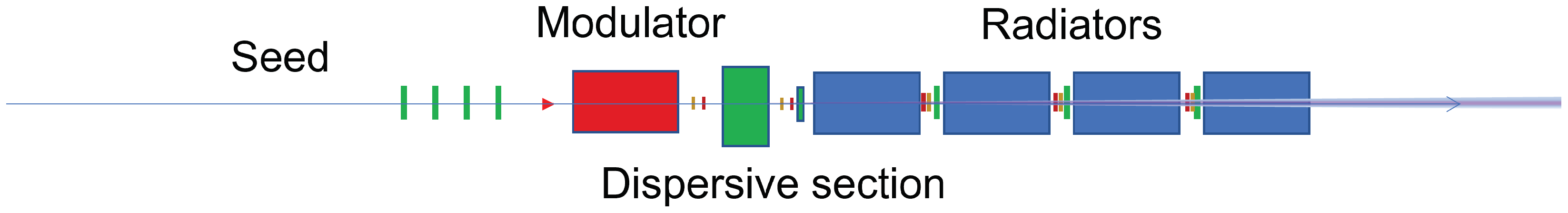
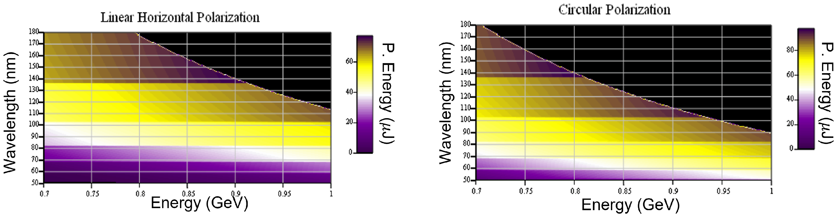
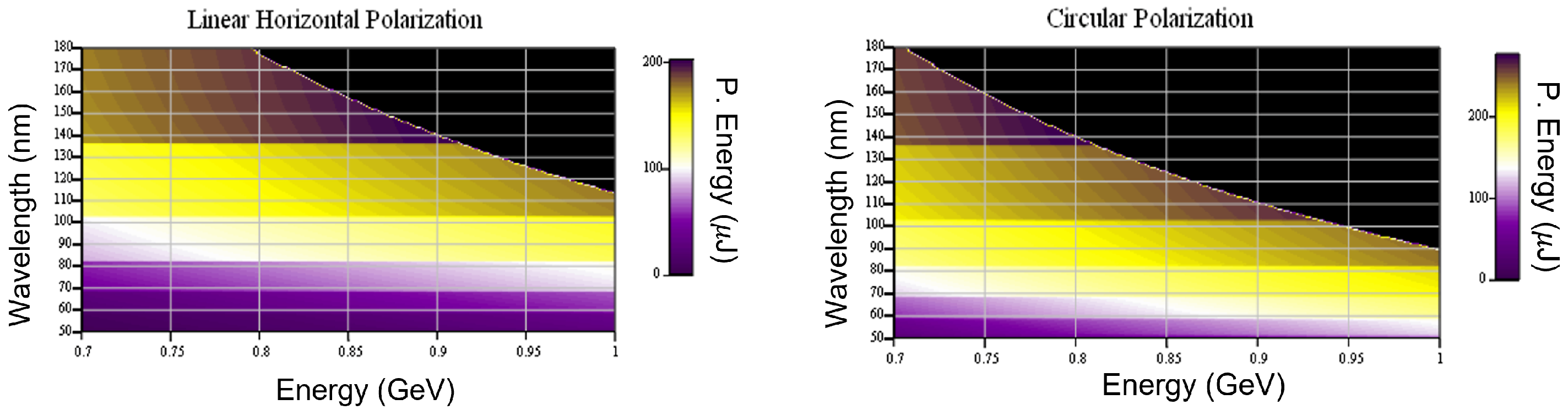
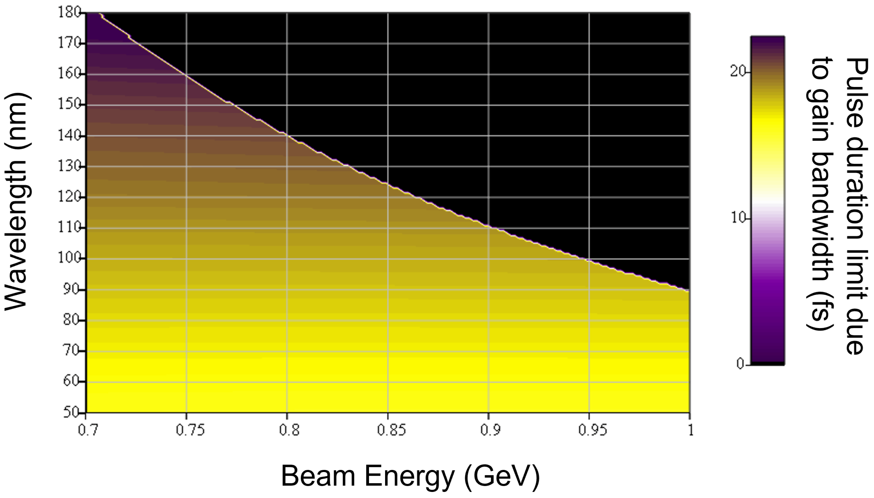
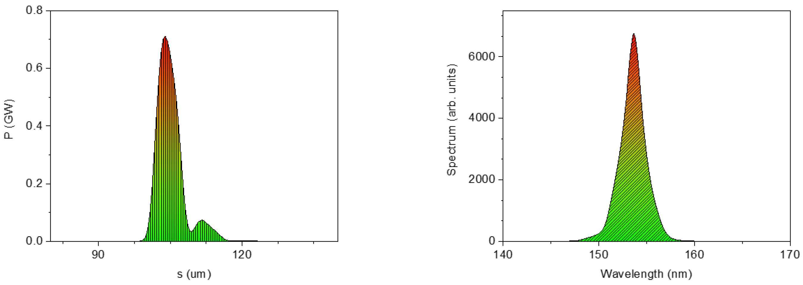
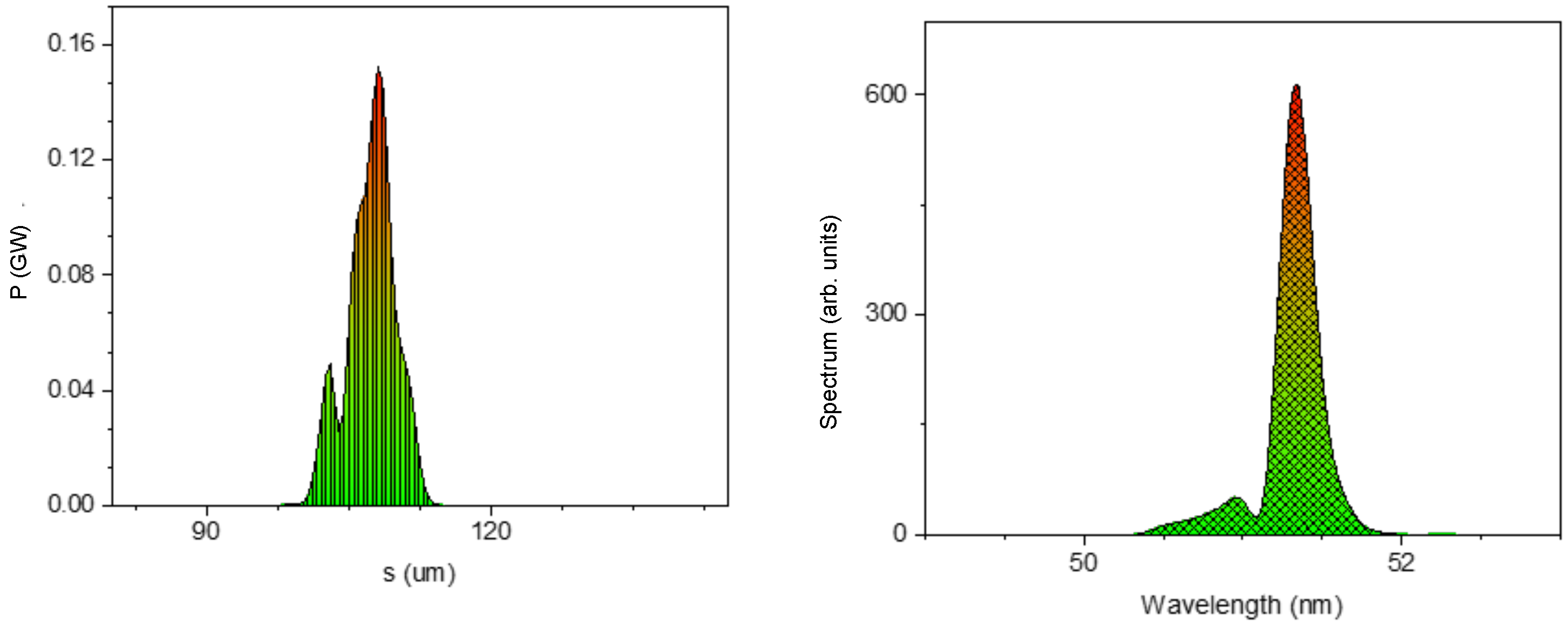
2. FEL Simulations for ARIA Beamline

The seeded FEL beamline ARIA exploits the standard High-Gain Harmonic Generation (HGHG) configuration for a continuous tunability in the VUV wavelength spectrum between 50 and 180 nm [23,24,25]. Its compact layout is sketched in Figure 2: the electron bunches are initially energy-modulated by the seed pulse in a 3-meter-long modulator, followed by a dispersive section for electron density modulation at higher harmonics of the seed and a final amplification stage. Table 2 and Table 3 list the main characteristics of the undulators and the seeding source, respectively.
The electron bunches entering the line can be either accelerated in a conventional LINAC or in a plasma module, and are then seeded by a long seed pulse: this flexibility enables operation in the long and short pulse modes. In the first case, long and high-charge electron bunches from the LINAC generate narrow line-width photon pulses suitable for spectroscopic applications, and can be eventually combined with a monochromator. In the second case, short and low-charge electron bunches amplify a single longitudinal mode whose shot-to-shot stability and second-order coherence are ensured by the seed. The electron beam parameters for both beam modes are summarized in Table 4.
The expected performances in terms of photon pulse energy are evaluated by using the Xie model in both cases of linear and circular polarization [26]. The results for short electron bunches are shown in Figure 3.
In the analyzed electron beam energy range, pulse energies below 20 μ J are achieved between 50–70 nm in linear polarization, whereas larger energies of up to 60 μ J are obtained at longer wavelengths. The circular polarization allows us to achieve slightly larger (>20 μ J) photon energies for medium wavelengths of around 100 nm. The expected pulse energy in the long pulse mode is shown in Figure 4.
In this case, hundreds- μ J of pulse energies are obtained. Such energy values are already reached in the short wavelength range of around 70 nm in circular polarization.
The ARIA line is capable of producing FEL pulses characterized by an energy of 10–100 μ J and very short pulse durations, determined by the short electron bunch duration and the large gain bandwidth. The latter is itself proportional to the FEL parameter ρ 3 D and to the ratio L t o t S A S E L u when L u < L t o t S A S E : a large ρ 3 D parameter in the long wavelength range and the presence of the seed, together with short and high-current electron bunches, enable the generation of ultra-short pulses. Figure 5 shows the expected pulse durations for a 15 fs bunch duration in circular polarization, evaluated as the FT limit of the bandwidth resulting from Xie scaling relations.
A range of 10–15 fs pulses are produced in the shorter wavelength range, whereas the pulse duration grows up to 20 fs for wavelengths larger than 100 nm.
The FEL line has been simulated with the three-dimensional FEL code GENESIS 1.3 used in a time-dependent mode with the maximum available precision [27]. An ideal and short electron beam, as the one reported in the third column of Table 4, with the maximum energy of 1 GeV, is considered. This electron beam is seeded by a FT-limited laser pulse whose main characteristics are listed in Table 3. The choice of a long wavelength seed simplifies the switch between two OPA processes, allowing it to cover the full wavelength range (after second harmonic generation) with harmonic orders 3–9. The harmonic emission is optimized by tuning the seed intensity and the dispersion strength.
Figure 6 and Figure 7 show the simulated FEL pulse temporal profile and spectral amplitude for a maximum wavelength of ∼153 nm (corresponding to the third harmonic of the seed) and a minimum wavelength of ∼51 nm (ninth harmonic), respectively.
Early saturation for lower harmonic orders ( 5 ) deteriorates and stretches the output pulse. This can be avoided by considering larger seed intensities and opening one radiator, which is eventually used for pulse gymnastics or to generate double pulses [28,29]. A summary of the final radiation pulse properties for the different harmonics is presented in Table 5.
For the emission of lower harmonics, the extraction after three radiators is also presented; then, ∼10 μ J pulse energies and a ∼15 fs pulse duration are achieved in the whole spectral range. Shorter wavelength seeds (i.e., third harmonic generation of Ti:Sa) can be considered for operations at shorter wavelengths.

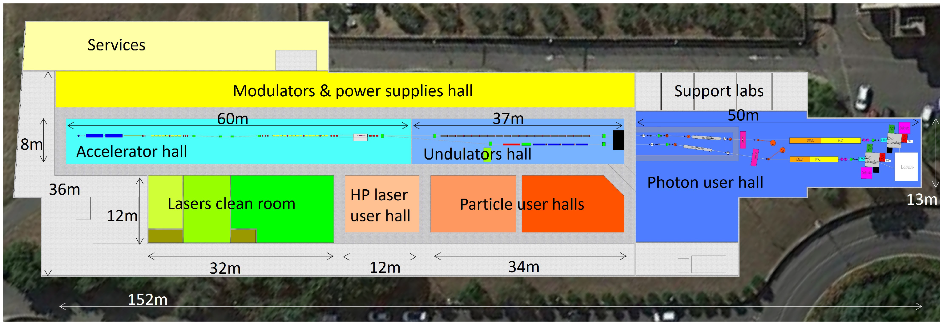
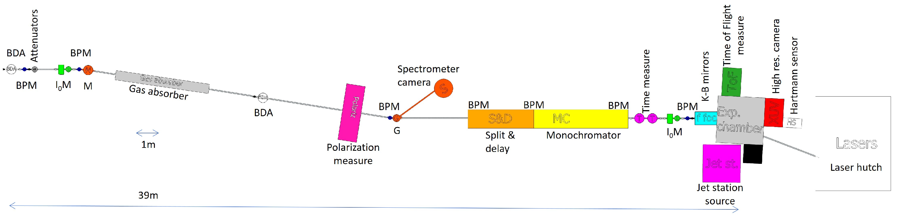
3. ARIA Beamline Configuration

After the undulator, approximately 50 m of the beamline will deliver the photon beam to an experimental chamber.
The beamline layout is presented in Figure 8. All of its elements can be divided into two different conceptual groups: beam transport and beam diagnostics.

3.1. Beam Transport and Controls

The first beamline element is a beam-defining aperture (BDA) that closes around the beam to preserve the beamline equipment from large fluctuations or beam misalignment without affecting the main pulse. A second function of those apertures is to remove the broader spontaneous radiation propagating along the beam with a larger angular divergence, thus acting as a collimator. The first aperture will be composed by two independently moving pyramid trunks in order to have the possibility of completely stopping the beam and of adjusting the aperture position to the desired coordinate. This shape allows for a higher pulse intensity as the blades are angled to increase the irradiate surface. A second round aperture will be inserted near the grating spectrometer to better collimate the beam.
We plan to monitor the trajectory of the photons with Beam Position Monitors (BPMs) along the line. These BPMs are composed of four metallic blades collecting a drain current from intercepting the very edges of the beam [20] in order to have minimal diffraction and absorption effects. We expect to have a spatial resolution of approximately two microns RMS [30] from the reference. We also expect that the seeding laser will have a strong impact on the shot-to-shot pointing stability compared to the usual fluctuations in the SASE configuration. The slow drifts, usually due to thermal effects, can be corrected when monitoring the BPMs, and have a feedback system on the mirror actuators.
Few mirrors are required for steering the beam away from the undulator line for radio protection reasons, as the first part of the beamline will be hosted in a dedicated bunker to block gas bremsstrahlung radiation. Mirrors are also used in other systems; in particular, for a monochromator, for a split and delay system and for final beam focusing. Each mirror will be controlled in two angular degrees of freedom and in the insertion direction. In order to have low enough losses, the mirrors will work at an angle of approximately 9 in the horizontal plane. This tilt also has the desired property of increasing the beam-irradiated area, reducing the surface intensity seed by the mirror coating well below the damage threshold. We are currently investigating the reflectivity of different kinds of coatings to match the spectral range of the beamline. We expect that C- or Al-coated mirrors can reach a reflectivity in the order of 80% for the planned spectral range.
For the final focusing of the beam on the experimental target, we plan to use two spherical or plane elliptical mirrors in a Kirkpatrick–Baez configuration. This curvature can be fixed as manufactured or slightly changed by a bending system on the mirrors [31] in the range of approximately 1 to 2 m. (e.g., the minimal focal length of the bent mirror at FERMI is ∼1.2 m [32]). The expected final RMS spot size will depend on the experiment requests and the source parameters, where the minimal spot size can be evaluated in the order of some tens of micrometers. We are also considering other focusing devices, such as multi-channel plates (MCPs) [33,34,35], to further improve the beamline characteristics and its compactness.
Some pump–probe experiments will require a split and delay system, which can be inserted only for those experiments in order to avoid unwanted losses due to mirror reflectivity. This system (like those in [36] or [37]) uses the edge of the mirrors to split and recombine the beam transversally and to give the two pulses a geometrical delay ranging from zero to a few hundreds fs.
Another high loss element that will be used only if required is the monochromator. We plan to use a grating monochromator in a configuration of closed dispersion [38] to avoid pulse front tilt; thus, there is an increase in the time length of the pulse. A Hartmann sensor (routinely implemented at FELs facilities [39]) will check the arrival pulse front at the target.
The beamline also requires an attenuator for the photon energy to better suit the experiments. We plan to initially use only thin film attenuators of different thicknesses, whereas, in the second phase, we plan to implement a gas attenuator at the beginning of the beamlines to achieve a finer control in the photon pulse energy for experimental purposes (e.g., for investigations of non-linear processes), sustaining a cost increase for the device and the pumping system.

3.2. Beam Diagnostics

We will use a gas-based intensity monitor to measure the number of photons per pulse, like those employed at FLASH [40] and FERMI [30], studying the best suitable gas for photoionization on the machine spectral range. We plan to have one detector at the beginning of the beamline near the BDA and another just before the final focus to accurately measure the shot-by-shot energy sent to the experiment. Other techniques to complement the gas intensity monitor, e.g., photodiode and using photoemissions from the metallic coating of the mirrors, are also under study. The photodiode will also be used during the commissioning and first alignment of the FEL line to characterize the FEL generation process and to tune the seeding intensity, as has been demonstrated at FERMI [41].
A few scintillator screens will be installed along the beamline in order to have an offline measurement of the beam size and shape. We plan to use a diagnostic chamber that is very similar to the one implemented for electron beam diagnostics to increase modularity. The scintillating medium will be a YAG:Ce crystal, which is known for its cost-effectiveness, is commonly used in FEL lines because of the high light yield (approximately 8 photons/keV [42]) and can also be used as a replacement for electron beam diagnostics, reducing the number of different spare parts required by the machine.
The precise measure of the time length and the arrival time is very important for the ultrashort FEL pulses (as reported in [43]). Many technologies and methods have been considered and tested [44] for the characterization of short VUV-X ray pulses. For pulses longer than a few hundred fs, commercial streak cameras have enough resolution to characterize the pulses. Commercially available fast photodiodes can be used for slower pulses (few tens ps) and for time arrival monitoring, in addition to being useful for energy measurements. For shorter beams, other techniques are used, involving nonlinear processes, such as cross-correlation [45] or transient reflectivity [46], using interferometry [47,48] or inferring the duration from the FEL-induced lasing effects on the electron beam after the undulators [49]. The technique we plan to develop and employ in our beamline will employ the ionization time-of-flight streaking with THz [50] or IR [51,52,53] wavelengths, which can achieve a sub-fs resolution on single-shot, non-intercepting measurements. The choice of the laser streaking wavelength will depend on the time length of the expected pulse regime, as the time window scales with the laser wavelength (e.g., ∼35 fs for 10.6 μ m laser wavelength [52]), whereas the time resolution is inversely proportional to the wavelength (e.g., ∼500 fs for the same 10.6 μ m wavelength [52]). This time-of-flight technique will also give information on the pulse arrival time [50].
Moreover, we plan to measure both the spatial and the temporal coherence of the beam using an interferometer, in either the Michelson [54] or the Fizeau configuration. The coherence measurement will be performed inside the experimental chamber in a removable configuration, as the interferometer will intercept the beam and requires a multishot measurement.
We’ll use a spectrometer with diffraction gratings to measure the pulse spectrum [30,55]. After the mirrors are used for deflecting the beam outside the undulator line, a grating will be used in a configuration where the reflected beam will be sent toward the experimental chamber in its 0th order, whereas we measure the first diffracted order with a CCD camera to retrieve the spectral information. In a first evaluation of the resolution, using a 2400 grooves/mm grating, 100 nm of central wavelength and 3 m of propagation from the grating, one camera pixel (approximately 13 microns for a back illuminated soft X-ray camera) will cover 1.2 × 10 3 nm (approximately 1% of the expected spectral width) at an angle of approximately 32.6 . Commercial back-illuminated cameras require only a small fraction of the photon beam to be employed due to their signal-to-noise ratio and excellent quantum efficiency on the order of 30%.

3.3. Experimental Endstation

The experimental end-station foreseen for the ARIA beamline will be equipped with the instruments necessary to perform the photo emission experiments described in the following section. The vacuum experimental chamber will contain state-of-the-art sample delivery systems and detectors.
Concerning the sample delivery, the injection of both liquid jets and aerosols will be possible. For liquid jets, different kinds of micro-jets, based on the gas dynamic virtual nozzle technology described in [56], including those developed for sample mixing [57] and for a lower sample consumption at pulsed sources [58], will be available. Molecules in the gas phase will instead be injected using an aerosol source, such as the one described in [59]. Moreover, the chamber will have the possibility of hosting solid samples mounted on motorized micro-precision stages and/or hexapod-like devices.
Concerning the detectors, an energy-resolved photon detector will be mounted to allow for the performing of different types of spectroscopic measurements. A time-of-flight spectrometer [60] connected to the experimental chamber will be used to analyze the ions and molecules produced by the sample–beam interaction.
Finally, an inlet for an external laser will allow for the performing of laser pump/FEL–probe time-resolved experiments.

4. Scientific Goals of ARIA Beamline

ARIA can provide many different experimental opportunities for investigations with pump–probe techniques in the fields of atomic, molecular and cluster physics, as well as in the study of gas adsorbates at interfaces and liquids.
The structure of small and large clusters is a topical issue under continuous development at third and fourth generation synchrotron facilities. Such studies on free clusters and thin solid films obtained from their deposition aim to follow the evolution of the properties of the matter, starting from a single isolated particle toward the surface and bulk condensed phases, and passing through steps of atomic and molecular aggregates of increasing complexity [61,62,63]. Given the extremely low number of target particles in cluster experiments, great advances are expected at a VUV-FEL, such as the ARIA beamline. Although an experimental effort has been directed toward studies on rare gases and molecular clusters, studies on aggregates of elements with high vaporization temperatures are still in their infancy. The main goal of such studies is to look at the formation of free clusters of varying chemical nature [64] by implementing resonant techniques in the VUV range. Indeed, the ability of the VUV-FEL to shift the wavelength of the scattered light from the visible into the deep UV will allow us to probe new electronic transitions well within the 7–20 eV range for classes of cluster materials, such as nano-carbons, and potential gap dielectrics, such as metal oxides.
More generally, the photon energy range of ARIA will give access to the photo-ionization thresholds and to the valence ionic states of atmospheric constituents from the troposphere, up to the ionosphere, and its pulsed time structure makes it an ideal source not only for spectroscopy, but also to study dynamics induced by light in such complex media with state-of-the-art mass spectrometric and electron spectrometry techniques [65]. The same applies to biosphere constituents, where the possibility of changing the polarization of the FEL light from linear to circular allows us to obtain important information, e.g., correlating chirality and natural dichroism in biotic media to the electronic structure of their basic constituents. The high brightness of this FEL source will enable the first direct analysis of systems with low density, as well as spectroscopic studies of exotic species.
A VUV monochromatic beamline, together with photo-emission techniques, would allow for the study of species of interest in both the physics of the upper atmosphere and in combustion. The electronic structure of these species has been extensively studied in the optical range but is not very well known in the region of photo-ionization due to the lack of high-intensity sources at wavelengths below 180 nm.
Besides photo-emission experiments, measurements in which molecules are photo-dissociated by the bright wavelength-tunable FEL pulses, and where the fragments are then analyzed by time-of-flight spectroscopy, will also be possible. Pilot measurements of this kind, in the same photon energy range that will be covered by ARIA, have already been performed at the Dalian coherent light source [66].
Finally, ARIA also represents a perfect source for two-photon photo emission (2PPE) experiments, a technique that matches the advantages of direct and inverse photo emission. In the time-resolved pump (external laser) and probe (FEL) configuration, it provides a powerful tool for the investigation of excited states, such as excitons, polarons, spin-charge-orbital ordering and the like [67]. Such states can be strongly modified in confined structures or in hybrid organic–inorganic hetero-junctions of organic solar cells [68], as well as in modulation-doped semiconductor heterostructures of metal–semiconductor interfaces, and spintronics devices such as spin valves or diluted magnetic semiconductors. The use of FEL sources with tunable energy may be crucial to enhance the resonant photo emission mechanism from more-or-less shallow levels beyond the limitation imposed by a low-frequency laser or low-intensity plasma/discharge UV lamps, allowing for a precise targeting of excited states via Fermi surface mapping.

5. Conclusions

This work investigated the feasibility of a compact and cost-effective FEL facility in the VUV spectral region. We presented FEL simulations of the emitted radiation, an overview of the beam transport and diagnostics and some of the possible applications. This FEL combines the possibility of delivering close to Fourier transform limit pulses with a high degree of polarization that is also controllable [69], with the possibility of tuning the pulse duration in two different conditions—ultrashort pulses allowed by the large gain bandwidth, and intensity- and spectrally stable ultra-narrow bandwidth pulses when used in combination with a monochromator.
This beamline may contribute to the scientific investigation in atomic, molecular and cluster physics, broadening the possibilities offered by existing FELs or alternative sources in the VUV spectral region, such as harmonics emitted in gas.

Author Contributions

Conceptualization, FEL: L.G., M.O., V.P., beamline, Z.E., F.V., scientific case and endstation: M.C., Z.E., A.M., F.S.; writing—original draft preparation, M.O., F.S., F.V.; writing—review and editing, all of the authors. All authors have read and agreed to the published version of the manuscript.

Funding

This work has been partially supported by the European Union Horizon 2020 research and innovation program, Grant Agreement No. 653782 (EuPRAXIA).

Data Availability Statement

The data that support the simulations of this study are available from the corresponding author upon reasonable request.

Conflicts of Interest

The authors declare no conflict of interest.

References

  1. Bostedt, C.; Boutet, S.; Fritz, D.M.; Huang, Z.; Lee, H.J.; Lemke, H.T.; Robert, A.; Schlotter, W.F.; Turner, J.J.; Williams, G.J. Linac Coherent Light Source: The first five years. Rev. Mod. Phys. 2016, 88, 015007. [Google Scholar] [CrossRef] [Green Version]
  2. Pellegrini, C.; Marinelli, A.; Reiche, S. The physics of X-ray free-electron lasers. Rev. Mod. Phys. 2016, 88, 015006. [Google Scholar] [CrossRef]
  3. Ackermann, W.A.; Asova, G.; Ayvazyan, V.; Azima, A.; Baboi, N.; Bähr, J.; Balandin, V.; Beutner, B.; Brandt, A.; Bolzmann, A.; et al. Operation of a free-electron laser from the extreme ultraviolet to the water window. Nat. Photonics 2007, 1, 336. [Google Scholar] [CrossRef]
  4. Emma, P.; Akre, R.; Arthur, J.; Bionta, R.; Bostedt, C.; Bozek, J.; Brachmann, A.; Bucksbaum, P.; Coffee, R.; Decker, F.J.; et al. First lasing and operation of an ångstrom-wavelength free-electron laser. Nat. Photonics 2010, 4, 641. [Google Scholar] [CrossRef]
  5. Huang, Z.; Lindau, I. SACLA hard-X-ray compact FEL. Nat. Photonics 2012, 6, 505–506. [Google Scholar] [CrossRef]
  6. Allaria, E.; Badano, L.; Bassanese, S.; Capotondi, F.; Castronovo, D.; Cinquegrana, P.; Danailov, M.B.; D’auria, G.; Demidovich, A.; De Monte, R.; et al. The FERMI free-electron lasers. J. Synchrotron Radiat. 2015, 22, 485–491. [Google Scholar] [CrossRef]
  7. Ko, I.S.; Kang, H.S.; Heo, H.; Kim, C.; Kim, G.; Min, C.K.; Yang, H.; Baek, S.Y.; Choi, H.J.; Mun, G.; et al. Construction and commissioning of PAL-XFEL facility. Appl. Sci. 2017, 7, 479. [Google Scholar] [CrossRef]
  8. Harm, M.; Coffee, R.; Bionta, M.R.; Chollet, M.; French, D.; Zhu, D.; Fritz, D.M.; Lemke, H.T.; Medvedev, N.; Ziaja, B.; et al. Achieving few-femtosecond time-sorting at hard X-ray free-electron lasers. Nat. Photonics 2013, 7, 215. [Google Scholar]
  9. Kang, H.S.; Min, C.K.; Heo, H.; Kim, C.; Yang, H.; Kim, G.; Nam, I.; Baek, S.Y.; Choi, H.J.; Mun, G.; et al. Hard X-ray free-electron laser with femtosecond-scale timing jitter. Nat. Photonics 2017, 11, 708. [Google Scholar] [CrossRef]
  10. Schulz, S.; Grguraš, I.; Behrens, C.; Bromberger, H.; Costello, J.T.; Czwalinna, M.K.; Felber, M.; Hoffmann, M.C.; Ilchen, M.; Liu, H.Y.; et al. Femtosecond all-optical synchronization of an X-ray free-electron laser. Nat. Commun. 2015, 6, 5938. [Google Scholar] [CrossRef] [Green Version]
  11. Esarey, E.; Schroeder, C.B.; Leemans, W.P. Physics of laser-driven plasma-based electron accelerators. Rev. Mod. Phys. 2009, 81, 1229. [Google Scholar] [CrossRef]
  12. Rosenzweig, J.B.; Breizman, B.; Katsouleas, T.; Su, J.J. Acceleration and focusing of electrons in two-dimensional nonlinear plasma wake fields. Phys. Rev. A 1991, 44, R6189–R6192. [Google Scholar] [CrossRef] [PubMed]
  13. Leemans, W.P.; Nagler, B.; Gonsalves, A.J.; Tóth, C.; Nakamura, K.; Geddes, C.G.; Esarey, E.; Schroeder, C.; Hooker, S. GeV electron beams from a centimetre-scale accelerator. Nat. Phys. 2006, 2, 696–699. [Google Scholar] [CrossRef]
  14. Blumenfeld, I.; Clayton, C.E.; Decker, F.J.; Hogan, M.J.; Huang, C.; Ischebeck, R.; Iverson, R.; Joshi, C.; Katsouleas, T.; Kirby, N.; et al. Energy doubling of 42 GeV electrons in a metre-scale plasma wakefield accelerator. Nature 2007, 445, 741–744. [Google Scholar] [CrossRef]
  15. Rosenzweig, J.; Andonian, G.; Ferrario, M.; Muggli, P.; Williams, O.; Yakimenko, V.; Xuan, K. Plasma Wakefields in the Quasi-Nonlinear Regime. In AIP Conference Proceedings; American Institute of Physics: New York, NY, USA, 2010; Volume 1299, pp. 500–504. [Google Scholar]
  16. Litos, M.; Adli, E.; An, W.; Clarke, C.I.; Clayton, C.E.; Corde, S.; Delahaye, J.P.; Engl, R.J.; Fisher, A.S.; Frederico, J.; et al. High-efficiency acceleration of an electron beam in a plasma wakefield accelerator. Nature 2014, 515, 92–95. [Google Scholar] [CrossRef]
  17. Romeo, S.; Chiadroni, E.; Croia, M.; Ferrario, M.; Giribono, A.; Marocchino, A.; Mira, F.; Pompili, R.; Rossi, A.R.; Vaccarezza, C. Simulation design for forthcoming high quality plasma wakefield acceleration experiment in linear regime at SPARC_LAB. Nucl. Instrum. Methods Phys. Res. Sect. A 2018, 909, 71–75. [Google Scholar] [CrossRef]
  18. Assmann, R.; Weikum, M.; Akhter, T.; Alesini, D.; Alexandrova, A.; Anania, M.; Andreev, N.; Andriyash, I.; Artioli, M.; Aschikhin, A.; et al. EuPRAXIA conceptual design report. Eur. Phys. J. Spec. Top. 2020, 229, 3675–4284. [Google Scholar] [CrossRef]
  19. Ferrario, M.; Alesini, D.; Anania, M.P.; Artioli, M.; Bacci, A.; Bartocci, S.; Bedogni, R.; Bellaveglia, M.; Biagioni, A.; Bisesto, F.; et al. EuPRAXIA@SPARC_LAB Design study towards a compact FEL facility at LNF. Nucl. Instrum. Methods Phys. Res. Sect. A 2018, 909, 134–138. [Google Scholar] [CrossRef]
  20. Villa, F.; Cianchi, A.; Coreno, M.; Dabagov, S.; Marcelli, A.; Minicozzi, V.; Morante, S.; Stellato, F. Design study of a photon beamline for a soft X-ray FEL driven by high gradient acceleration at EuPRAXIA@ SPARC_LAB. Nucl. Instrum. Methods Phys. Res. Sect. A 2018, 909, 294–297. [Google Scholar] [CrossRef]
  21. Villa, F.; Balerna, A.; Chiadroni, E.; Cianchi, A.; Coreno, M.; Dabagov, S.; Cicco, D.; Gunnella, R.; Marcelli, A.; Masciovecchio, C.; et al. Photon Beam Line of the Water Window FEL for the EuPRAXIA@ SPARC_LAB Project; Journal of Physics: Conference Series; IOP Publishing: Bristol, UK, 2020; Volume 1596, p. 012039. [Google Scholar]
  22. Balerna, A.; Bartocci, S.; Batignani, G.; Cianchi, A.; Chiadroni, E.; Coreno, M.; Cricenti, A.; Dabagov, S.; Di Cicco, A.; Faiferri, M.; et al. The Potential of EuPRAXIA@SPARC_LAB for Radiation Based Techniques. Condens. Matter 2019, 4, 30. [Google Scholar] [CrossRef] [Green Version]
  23. Yu, L.H.; Babzien, M.; Ben-Zvi, I.; DiMauro, L.; Doyuran, A.; Graves, W.; Johnson, E.; Krinsky, S.; Malone, R.; Pogorelsky, I.; et al. High-gain harmonic-generation free-electron laser. Science 2000, 289, 932–934. [Google Scholar] [CrossRef] [PubMed] [Green Version]
  24. Yu, L.H.; DiMauro, L.; Doyuran, A.; Graves, W.; Johnson, E.; Heese, R.; Krinsky, S.; Loos, H.; Murphy, J.; Rakowsky, G.; et al. First ultraviolet high-gain harmonic-generation free-electron laser. Phys. Rev. Lett. 2003, 91, 074801. [Google Scholar] [CrossRef]
  25. Togashi, T.; Takahashi, E.J.; Midorikawa, K.; Aoyama, M.; Yamakawa, K.; Sato, T.; Iwasaki, A.; Owada, S.; Okino, T.; Yamanouchi, K.; et al. Extreme ultraviolet free electron laser seeded with high-order harmonic of Ti: Sapphire laser. Opt. Express 2011, 19, 317–324. [Google Scholar] [CrossRef] [PubMed]
  26. Xie, M. Design optimization for an X-ray free electron laser driven by SLAC linac. In Proceedings of the Particle Accelerator Conference, Dallas, TX, USA, 1–5 May 1995; Volume 1, pp. 183–185. [Google Scholar]
  27. Reiche, S. GENESIS 1.3: A fully 3D time-dependent FEL simulation code. Nucl. Instruments Methods Phys. Res. Sect. A Accel. Spectrometers Detect. Assoc. Equip. 1999, 429, 243–248. [Google Scholar] [CrossRef]
  28. Petrillo, V.; Anania, M.; Artioli, M.; Bacci, A.; Bellaveglia, M.; Chiadroni, E.; Cianchi, A.; Ciocci, F.; Dattoli, G.; Di Giovenale, D.; et al. Observation of time-domain modulation of free-electron-laser pulses by multipeaked electron-energy spectrum. Phys. Rev. Lett. 2013, 111, 114802. [Google Scholar] [CrossRef] [PubMed] [Green Version]
  29. Petralia, A.; Anania, M.; Artioli, M.; Bacci, A.; Bellaveglia, M.; Carpanese, M.; Chiadroni, E.; Cianchi, A.; Ciocci, F.; Dattoli, G.; et al. Two-color radiation generated in a seeded free-electron laser with two electron beams. Phys. Rev. Lett. 2015, 115, 014801. [Google Scholar] [CrossRef] [Green Version]
  30. Zangrando, M.; Abrami, A.; Bacescu, D.; Cudin, I.; Fava, C.; Frassetto, F.; Galimberti, A.; Godnig, R.; Giuressi, D.; Poletto, L.; et al. The photon analysis, delivery, and reduction system at the FERMI@ Elettra free electron laser user facility. Rev. Sci. Instrum. 2009, 80, 113110. [Google Scholar] [CrossRef]
  31. Raimondi, L.; Svetina, C.; Mahne, N.; Cocco, D.; Abrami, A.; De Marco, M.; Fava, C.; Gerusina, S.; Gobessi, R.; Capotondi, F.; et al. Microfocusing of the FERMI@ Elettra FEL beam with a K–B active optics system: Spot size predictions by application of the WISE code. Nucl. Instrum. Methods Phys. Res. Sect. A 2013, 710, 131–138. [Google Scholar] [CrossRef]
  32. Allaria, E.; Callegari, C.; Cocco, D.; Fawley, W.M.; Kiskinova, M.; Masciovecchio, C.; Parmigiani, F. The FERMI@ Elettra free-electron-laser source for coherent X-ray physics: Photon properties, beam transport system and applications. New J. Phys. 2010, 12, 075002. [Google Scholar] [CrossRef]
  33. Dabagov, S.B.; Marcelli, A.; Murashova, V.A.; Svyatoslavsky, N.L.; Fedorchuk, R.V.; Yakimenko, M.N. Coherent and incoherent components of a synchrotron radiation spot produced by separate capillaries. Appl. Opt. 2000, 39, 3338–3343. [Google Scholar] [CrossRef] [PubMed]
  34. Mazuritskiy, M.; Dabagov, S.; Marcelli, A.; Lerer, A.; Dziedzic-Kocurek, K. Excitation and propagation of X-ray fluorescence through thin devices with hollowed ordered structures: Comparison of experimental and theoretical spectra. J. Synchrotron Radiat. 2016, 23, 274–280. [Google Scholar] [CrossRef]
  35. Mazuritskiy, M.; Lerer, A.; Marcelli, A.; Dabagov, S. Synchrotron radiation transmission by two coupled flat microchannel plates: New opportunities to control the focal spot characteristics. J. Synchrotron Rad. 2022, 29. in press. [Google Scholar] [CrossRef]
  36. Wöstmann, M.; Mitzner, R.; Noll, T.; Roling, S.; Siemer, B.; Siewert, F.; Eppenhoff, S.; Wahlert, F.; Zacharias, H. The XUV split-and-delay unit at beamline BL2 at FLASH. J. Phys. B: At. Mol. Opt. Phys. 2013, 46, 164005. [Google Scholar] [CrossRef] [Green Version]
  37. Castagna, J.; Murphy, B.; Bozek, J.; Berrah, N. X-ray split and delay system for soft X-rays at LCLS. J. Phys. Conf. Ser. 2013, 425, 152021. [Google Scholar] [CrossRef]
  38. Frassetto, F.; Poletto, L.; Ploenjes, E.; Kuhlmann, M. Double-grating monochromator for ultrafast Free-Electron-Laser beamlines. In Proceedings of the FEL Conference, Basilea, Switzerland, 25–29 August 2014. [Google Scholar]
  39. Svetina, C.; Grazioli, C.; Mahne, N.; Raimondi, L.; Fava, C.; Zangrando, M.; Gerusina, S.; Alagia, M.; Avaldi, L.; Cautero, G.; et al. The Low Density Matter (LDM) beamline at FERMI: Optical layout and first commissioning. J. Synchrotron Radiat. 2015, 22, 538–543. [Google Scholar] [CrossRef]
  40. Richter, M.; Gottwald, A.; Kroth, U.; Sorokin, A.A.; Bobashev, S.V.; Shmaenok, L.A.; Feldhaus, J.; Gerth, C.; Steeg, B.; Tiedtke, K.; et al. Measurement of gigawatt radiation pulses from a vacuum and extreme ultraviolet free-electron laser. Appl. Phys. Lett. 2003, 83, 2970–2972. [Google Scholar] [CrossRef]
  41. Di Cicco, A.; Bencivenga, F.; Battistoni, A.; Cocco, D.; Cucini, R.; D’Amico, F.; Di Fonzo, S.; Filipponi, A.; Gessini, A.; Giangrisostomi, E.; et al. Probing matter under extreme conditions at Fermi@Elettra: The TIMEX beamline. In Damage to VUV, EUV, and X-Ray Optics III; Juha, L., Bajt, S., London, R.A., Eds.; International Society for Optics and Photonics, SPIE: Washington, DC, USA, 2011; Volume 8077, pp. 18–27. [Google Scholar] [CrossRef]
  42. Gerasimova, N.; Treusch, R.; Dziarzhytski, S.; Sinn, H. The Photon Beam Loss Monitors as a Part of Equipment Protection System at European XFEL. In Proceedings of the 36th International Free Electron Laser Conference, Basel, Switzerland, 25–29 August 2014; Number PUBDB-2014-03602. p. MOP010. [Google Scholar]
  43. Helml, W.; Grguraš, I.; Juranić, P.N.; Düsterer, S.; Mazza, T.; Maier, A.R.; Hartmann, N.; Ilchen, M.; Hartmann, G.; Patthey, L.; et al. Ultrashort Free-Electron Laser X-ray Pulses. Appl. Sci. 2017, 7, 915. [Google Scholar] [CrossRef] [Green Version]
  44. Duesterer, S.; Rehders, M.; Al-Shemmary, A.; Behrens, C.; Brenner, G.; Brovko, O.; DellAngela, M.; Drescher, M.; Faatz, B.; Feldhaus, J.; et al. Development of experimental techniques for the characterization of ultrashort photon pulses of extreme ultraviolet free-electron lasers. Phys. Rev. Spec. Top. Accel Beams 2014, 17, 120702. [Google Scholar] [CrossRef] [Green Version]
  45. Finetti, P.; Höppner, H.; Allaria, E.; Callegari, C.; Capotondi, F.; Cinquegrana, P.; Coreno, M.; Cucini, R.; Danailov, M.B.; Demidovich, A.; et al. Pulse duration of seeded free-electron lasers. Phys. Rev. X 2017, 7, 021043. [Google Scholar] [CrossRef] [Green Version]
  46. Riedel, R.; Al-Shemmary, A.; Gensch, M.; Golz, T.; Harm, M.; Medvedev, N.; Prandolini, M.J.; Sokolowski-Tinten, K.; Toleikis, S.; Wegner, U.; et al. Single-shot pulse duration monitor for extreme ultraviolet and X-ray free-electron lasers. Nat. Commun. 2013, 4, 1731. [Google Scholar] [CrossRef] [PubMed]
  47. De Ninno, G.; Gauthier, D.; Mahieu, B.; Ribič, P.R.; Allaria, E.; Cinquegrana, P.; Danailov, M.B.; Demidovich, A.; Ferrari, E.; Giannessi, L.; et al. Single-shot spectro-temporal characterization of XUV pulses from a seeded free-electron laser. Nat. Commun. 2015, 6, 8075. [Google Scholar] [CrossRef] [PubMed] [Green Version]
  48. Kayser, Y.; David, C.; Flechsig, U.; Krempasky, J.; Schlott, V.; Abela, R. X-ray grating interferometer for in situ and at-wavelength wavefront metrology. J. Synchrotron Radiat. 2017, 24, 150–162. [Google Scholar] [CrossRef] [PubMed] [Green Version]
  49. Behrens, C.; Decker, F.J.; Ding, Y.; Dolgashev, V.A.; Frisch, J.; Huang, Z.; Krejcik, P.; Loos, H.; Lutman, A.; Maxwell, T.J.; et al. Few-femtosecond time-resolved measurements of X-ray free-electron lasers. Nat. Commun. 2014, 5, 3762. [Google Scholar] [CrossRef] [PubMed]
  50. Grguraš, I.; Maier, A.R.; Behrens, C.; Mazza, T.; Kelly, T.J.; Radcliffe, P.; Düsterer, S.; Kazansky, A.K.; Kabachnik, N.M.; Tschentscher, T.; et al. Ultrafast X-ray pulse characterization at free-electron lasers. Nat. Photonics 2012, 6, 852. [Google Scholar] [CrossRef]
  51. Coffee, R.N.; Cryan, J.P.; Duris, J.; Helml, W.; Li, S.; Marinelli, A. Development of ultrafast capabilities for X-ray free-electron lasers at the linac coherent light source. Philos. Trans. R. Soc. A: Math. Phys. Eng. Sci. 2019, 377, 20180386. [Google Scholar] [CrossRef] [Green Version]
  52. Hartmann, N.; Hartmann, G.; Heider, R.; Wagner, M.S.; Ilchen, M.; Buck, J.; Lindahl, A.O.; Benko, C.; Grünert, J.; Krzywinski, J.; et al. Attosecond time—Energy structure of X-ray free-electron laser pulses. Nat. Photonics 2018, 12, 215–220. [Google Scholar] [CrossRef]
  53. Duris, J.; Li, S.; Driver, T.; Champenois, E.G.; MacArthur, J.P.; Lutman, A.A.; Zhang, Z.; Rosenberger, P.; Aldrich, J.W.; Coffee, R.; et al. Tunable isolated attosecond X-ray pulses with gigawatt peak power from a free-electron laser. Nat. Photonics 2020, 14, 30–36. [Google Scholar] [CrossRef] [Green Version]
  54. Hilbert, V.; Rödel, C.; Brenner, G.; Döppner, T.; Düsterer, S.; Dziarzhytski, S.; Fletcher, L.; Förster, E.; Glenzer, S.H.; Harmand, M.; et al. Spatio-temporal coherence of free-electron laser radiation in the extreme ultraviolet determined by a Michelson interferometer. Appl. Phys. Lett. 2014, 105, 101102. [Google Scholar] [CrossRef]
  55. Poletto, L.; Frassetto, F.; Miotti, P.; Di Cicco, A.; Finetti, P.; Grazioli, C.; Iesari, F.; Kivimki, A.; Stagira, S.; Coreno, M. Spectrometer for X-ray emission experiments at FERMI free-electron-laser. Rev. Sci. Instrum. 2014, 85, 103112. [Google Scholar] [CrossRef] [Green Version]
  56. DePonte, D.; Weierstall, U.; Schmidt, K.; Warner, J.; Starodub, D.; Spence, J.; Doak, R. Gas dynamic virtual nozzle for generation of microscopic droplet streams. J. Phys. D: Appl. Phys. 2008, 41, 195505. [Google Scholar] [CrossRef] [Green Version]
  57. Wang, D.; Weierstall, U.; Pollack, L.; Spence, J. Double-focusing mixing jet for XFEL study of chemical kinetics. J. Synchrotron Radiat. 2014, 21, 1364–1366. [Google Scholar] [CrossRef] [PubMed] [Green Version]
  58. Echelmeier, A.; Villarreal, J.C.; Messerschmidt, M.; Kim, D.; Coe, J.D.; Thifault, D.; Botha, S.; Egatz-Gomez, A.; Gandhi, S.; Brehm, G.; et al. Segmented flow generator for serial crystallography at the European X-ray free electron laser. Nat. Commun. 2020, 11, 1–10. [Google Scholar] [CrossRef] [PubMed]
  59. Bogan, M.J.; Boutet, S.; Chapman, H.N.; Marchesini, S.; Barty, A.; Benner, W.H.; Rohner, U.; Frank, M.; Hau-Riege, S.P.; Bajt, S.; et al. Aerosol imaging with a soft x-ray free electron laser. Aerosol Sci. Technol. 2010, 44, i–vi. [Google Scholar] [CrossRef]
  60. Arrell, C.; Ojeda, J.; Sabbar, M.; Okell, W.; Witting, T.; Siegel, T.; Diveki, Z.; Hutchinson, S.; Gallmann, L.; Keller, U.; et al. A simple electron time-of-flight spectrometer for ultrafast vacuum ultraviolet photoelectron spectroscopy of liquid solutions. Rev. Sci. Instruments 2014, 85, 103117. [Google Scholar] [CrossRef] [Green Version]
  61. Bostedt, C.; Gorkhover, T.; Rupp, D.; Möller, T. Clusters and nanocrystals. In Synchrotron Light Sources and Free-Electron Lasers: Accelerator Physics, Instrumentation and Science Applications; Springer: Berlin, Germany, 2020; pp. 1525–1573. [Google Scholar]
  62. Jaeschke, E.J.; Khan, S.; Schneider, J.R.; Hastings, J.B. Synchrotron Light Sources and Free-Electron Lasers: Accelerator Physics, Instrumentation and Science Applications; Springer: Berlin, Germany, 2016. [Google Scholar]
  63. Feifel, R.; Tchaplyguine, M.; Öhrwall, G.; Salonen, M.; Lundwall, M.; Marinho, R.; Gisselbrecht, M.; Sorensen, S.; de Brito, A.N.; Karlsson, L.; et al. From localised to delocalised electronic states in free Ar, Kr and Xe clusters. Eur. Phys. J. D-Atomic Mol. Opt. Plasma Phys. 2004, 30, 343–351. [Google Scholar] [CrossRef]
  64. Bogana, M.; Ravagnan, L.; Casari, C.S.; Zivelonghi, A.; Baserga, A.; Bassi, A.L.; Bottani, C.E.; Vinati, S.; Salis, E.; Piseri, P.; et al. Leaving the fullerene road: Presence and stability of sp chains in sp2 carbon clusters and cluster-assembled solids. New J. Phys. 2005, 7, 81. [Google Scholar] [CrossRef] [Green Version]
  65. Pathak, S.; Ibele, L.M.; Boll, R.; Callegari, C.; Demidovich, A.; Erk, B.; Feifel, R.; Forbes, R.; Di Fraia, M.; Giannessi, L.; et al. Tracking the ultraviolet-induced photochemistry of thiophenone during and after ultrafast ring opening. Nat. Chem. 2020, 12, 795–800. [Google Scholar] [CrossRef]
  66. Chang, Y.; Yu, S.; Li, Q.; Yu, Y.; Wang, H.; Su, S.; Chen, Z.; Che, L.; Wang, X.; Zhang, W.; et al. Tunable VUV photochemistry using vacuum ultraviolet free electron laser combined with H-atom Rydberg tagging time-of-flight spectroscopy. Rev. Sci. Instruments 2018, 89, 063113. [Google Scholar] [CrossRef]
  67. Höfer, U.; Shumay, I.; Reuß, C.; Thomann, U.; Wallauer, W.; Fauster, T. Time-resolved coherent photoelectron spectroscopy of quantized electronic states on metal surfaces. Science 1997, 277, 1480–1482. [Google Scholar] [CrossRef]
  68. Huang, Y.s.; Westenhoff, S.; Avilov, I.; Sreearunothai, P.; Hodgkiss, J.M.; Deleener, C.; Friend, R.H.; Beljonne, D. Electronic structures of interfacial states formed at polymeric semiconductor heterojunctions. Nat. Mater. 2008, 7, 483–489. [Google Scholar] [CrossRef] [PubMed]
  69. Allaria, E.; Diviacco, B.; Callegari, C.; Finetti, P.; Mahieu, B.; Viefhaus, J.; Zangrando, M.; De Ninno, G.; Lambert, G.; Ferrari, E.; et al. Control of the Polarization of a Vacuum-Ultraviolet, High-Gain, Free-Electron Laser. Phys. Rev. X 2014, 4, 041040. [Google Scholar] [CrossRef] [Green Version]
Figure 1. Layout of the EuPRAXIA@SPARC_LAB facility.
Condensedmatter 07 00011 g001
Figure 2. Layout of the ARIA HGHG FEL. The seed pulse is superimposed on the electron bunches at the modulator entrance, and the dispersive section is a four-dipole chicane that converts the energy modulation into a density modulation. Its length ∼2 m is kept constant and the dispersion strength is tuned by varying the dipole magnetic fields. The amplification stage is made up of four radiators.
Condensedmatter 07 00011 g002
Figure 3. Expected photon pulse energy in the short pulse mode as a function of the electron beam energy (x) and wavelength (y). (Left): linear polarization. (Right): circular polarization.
Condensedmatter 07 00011 g003
Figure 4. Expected photon pulse energy in the long pulse mode as a function of the electron beam energy (x) and wavelength (y). (Left): linear polarization. (Right): circular polarization.
Condensedmatter 07 00011 g004
Figure 5. Expected photon pulse duration as a function of the electron beam energy (x) and wavelength (y). A 15 fs electron bunch and circular polarization are assumed.
Condensedmatter 07 00011 g005
Figure 6. FEL emission at 153 nm, third harmonic of the 460 nm seed. (Left): pulse longitudinal power profile (GW) vs. s( μ m). (Right): spectral amplitude (arb. units) vs. λ (nm). Extraction is performed after three radiators.
Condensedmatter 07 00011 g006
Figure 7. FEL emission at 51 nm, ninth harmonic of the 460 nm seed. (Left): pulse longitudinal power profile (GW) vs. s( μ m). (Right): spectral amplitude (arb. units) vs. λ (nm). Extraction after four radiators.
Condensedmatter 07 00011 g007
Figure 8. Layout of the ARIA beamline. BDA, beam defining aperture; BPM, beam position monitors; I 0 M, intensity meters; M, steering mirror; G, diffraction grating.
Condensedmatter 07 00011 g008
Table 1. EuPRAXIA@SPARC_LAB parameters.
Electron and Undulator ParametersAQUA Radiation Parameters
Energy0.8–1.2 GeVWavelength3–4 nm
Energy spread0.1%Bandwidth0.15–0.23%
Emittance0.5 mm mradDimensions0.14–0.20 mm
Peak current2–3 kADuration5–50 fs rms
Und. period15 mmPhoton per pulse0.4–2.6 × 10 12
K0.9–1.45
Table 2. ARIA undulator line: undulator specifications. The use of APPLE-II undulators allows for the amplification of pulses with variable polarization. The dispersion strength in between the modulator and the amplifier is approximately 150 μ m.
PropertyModulatorRadiator
Length (m)34 × 2.1
Period length (cm)105.5
TypeApple-IIApple-II
Table 3. ARIA undulator line: seed laser specifications. The seed is a near-UV/blue laser that can be realized with commercial OPA amplifiers. The values considered in the reported simulations are indicated in parenthesis.
PropertySeed
Wavelength (nm)410–560 (460)
Pulse energy ( μ J)1–30
FWHM duration (fs)150–200 (180)
Table 4. Electron beam properties for the long and short pulse mode.
PropertyLong PulseShort Pulse
Energy (GeV)0.7–10.7–1
Peak current (kA)0.51.5
Bunch charge (pC)20030
Bunch duration (fs)3015
slice Energy spread ( 10 4 )1.53.5
slice norm. Emittance (mm mrad)0.80.8
Table 5. Radiation properties at saturation. * = extraction after three radiators.
Radiation Properties/HN33 * 44 * 55 * 79
Wavelength (nm)153153 * 115115 * 9292 * 6551
Seed energy ( μ J)1.22.8 * 85.6 * 88 * 3030
Photon energy ( μ J)2213 * 279.5 * 24.79 * 95
FWHM duration (fs)2516 * 2315 * 2015 * 1818
Photon/shot ( 10 13 )1.351.02 * 1.780.73 * 1.130.55 * 0.390.08
Bandwidth (%)0.850.95 * 0.710.7 * 0.630.67 * 0.430.4
Pulse size (mm)1.21.15 * 1.111.2 * 1.171.08 * 1.070.8
Pulse divergence ( mrad )0.680.62 * 0.480.45 * 0.380.34 * 0.270.2
Publisher’s Note: MDPI stays neutral with regard to jurisdictional claims in published maps and institutional affiliations.

