
Microstructural Analysis of Terbium Doped Zirconia and Its Biological Studies


School of Electronics Engineering, Vellore Institute of Technology, Vellore 632016, India
*
Author to whom correspondence should be addressed.
Condens. Matter 2022, 7(1), 20; https://0-doi-org.brum.beds.ac.uk/10.3390/condmat7010020
Submission received: 25 October 2021
/
Revised: 7 December 2021
/
Accepted: 17 December 2021
/
Published: 3 February 2022
(This article belongs to the Special Issue Electronic Materials and Devices 2021)
Abstract
:Zirconia has its place in the biomedical industry because of its mechanical strength, bio-inertness, and physiochemical properties. Zirconia was synthesized and doped with Terbium (Tb), a lanthanide that was reported to show a photoluminescence property, which was a major characteristic for carcinogenic studies. Zirconia and Tb doped Zirconia were synthesized using the co-precipitation technique and were sintered at a temperature ranging from 900 to 1200 °C. The Zirconia sample and Tb doped Zirconia were thus studied for structural diversities using the X-ray powder diffraction technique (XRD), FTIR, FE-SEM, and TEM. From XRD, Zirconia phase transformation from monoclinic to tetragonal phase was observed, which signified limited fracture, elasticity, and crack formation. It was evident that Terbium stabilized the tetragonal phase of Zirconia, which reportedly shows mechanical properties, which include fracture toughness and flexural strength. The particle size of the Zirconia was comparatively more than the Tb doped Zirconia. The particle size of Zirconia ranged between 176 nm and 393 nm and the particle size of Tb doped Zirconia ranged between 110 nm and 343 nm. The biocompatibility of both the samples was tested using an Mg-63 cell line, and the cell viability was observed to be higher in Tb doped Zirconia when compared to the undoped Zirconia sample.
1. Introduction
Zirconia is a ceramic that has been in the biomedical industry for years because of its important applications. Zirconia at ambient pressure and higher temperatures exists in three forms: at a temperature less than 1170 °C, Zirconia shows a monoclinic phase, at a temperature ranging from 1170 to 2370 °C, Zirconia shows a tetragonal phase, and at temperatures greater than 2706 °C, Zirconia shows a cubic phase [1,2,3,4,5]. Zirconia has various advantages such as biocompatibility, the proliferation of cells, better osseointegration, it is radiopaque, and it does not stock up in the tissues [6,7,8,9]. Zirconia exhibits great toughness, mechanical strength and the most important feature of Zirconia is it prevents propagation of cracks during phase transformation from the monoclinic to tetragonal phase [10,11].
Zirconia has been popular because of its inertness, i.e., it does not react chemically or biologically within the bodily environment [12,13,14,15]. Zirconia has not been a great success as a biomaterial, about 20 years ago, it proved to be a catastrophic failure in orthopedics due to hydrothermal aging; however, it remains significant in the dental ceramics field. Zirconia shows tremendous mechanical properties along with physicochemical properties when it exists in the tetragonal phase [16]. The tetragonal phase of Zirconia is usually stabilized by doping it with Yttria, Magnesia, Ceria, and Calcia [17,18,19,20]. A study showed that partially stabilized Zirconia exhibits a good fracture toughness when compared to other phases of Zirconia [21].
Zirconia coatings are cytocompatible and bioinert [22,23,24]. A study showed that the bioactivity of Zirconia can be improved by modifying the Zirconia-coated implant surface with micro-arc oxidation and exposing it to UV light [25]. Monoclinic Zirconia exhibited excellent bioactivity along with the proliferation of cells and adhesion when tested on MG-63 cell lines. The Zirconia-Hydroxyapatite composite showed better biocompatibility, bioactivity, and bonding strength [26,27,28,29].
The use of nanoparticles in medicine is a rapidly growing research field with numerous potential applications, especially in the field of cancer diagnosis and therapy. Nanoparticles can be intrinsically diagnostic or therapeutic, or they can be conjugated with diagnostic or therapeutic compounds. Nanoparticles may also passively or actively target cancer cells specifically using the enhanced permeation and retention (EPR) effect or the addition of targeting ligands to their surface. Trivalent Terbium ions have an electronic structure 4f8 and exhibit luminescence mainly due to 5D4 to 7FJ transitions. The partially stabilized Zirconium dioxide exhibited broad host-related emission peaking at 500 nm, disappearing with the Terbium content and Terbium stabilization of ZrO2 influenced the luminescence properties. The development of Tb-doped ZrO2 nanoparticles (NPs) is mainly used for application in cancer imaging. One of the studies confirmed alimentary absorption and wide distribution of luminescent ZrO2: Tb nanoparticles in mice with their gradual accumulation in the experimentally induced mammary cancers [30].
Zirconia acts as an outstanding host for Terbium which resulted in green luminophores [31]. Terbium is popular for its magnetic and luminescence properties. A study showed that Terbium stabilized the tetragonal phase of Zirconia and showcased various luminescence properties to the limelight. A study on luminescent properties of Terbium showed that Terbium emits in the blue-green spectrum range, which concluded that Terbium is sensitive to higher ranges of temperatures. Tb+3 ions exhibit luminescent properties, and the results were not favorable because of the formation of the Tb+4 ion [32].
In this paper, pure Zirconia and Tb stabilized Zirconia was prepared by the coprecipitation method. Zirconia was doped with various concentrations of Terbium (2–8%) to analyze various properties exhibited by the composite, which is considered to be a novel approach in this work, since not much research has been found with different concentrations of Terbium doped with Zirconia samples. These composites were used to analyze the particle size using FESEM and TEM. Phase transformation using XRD for the composite material was tested for future biomedical applications.
2. Materials and Methods
2.1. Synthesis of Zirconia
The Zirconium precursor used was 1M Zirconium oxychloride octahydrate (ZrOCl2·8H2O) in distilled water. In total, 2M NaOH was added to the 1M ZrOCl2·8H2O solution and stirred for 2 h, and the pH was checked and was maintained around 9. Once the stirring process was complete, the solution was kept aside to age for 24 h. The aged solution was washed using acetone to remove acid residues. The acetone wash was followed by drying the solution overnight. Any possible residues were further removed by washing with distilled water wash, dried overnight, and finally sintered at 900 °C, 1000 °C, 1200 °C, and 1300 °C.
2.2. Synthesis of Terbium Doped Zirconia
ZrOCl2·8H2O was dissolved in 50 mL distilled water. Various concentrations of Terbium such as 2%(1 gm), 4%(2 gms), 6%(3 gms), and 8%(4 gms) were dissolved in 50 mL distilled water and added to a 1M ZrOCl2·8H2O solution and stirred. After 15 min, 2M NaOH solution was added to the solution. The prepared solution was stirred for 2 h and left aside for 24 h. Later, the solution was washed using acetone and dried overnight. The minute contaminations were removed by washing with distilled water and drying overnight. The dried sample was sintered at 1300 °C.
2.3. Characterization
The Zirconia sample and Terbium doped Zirconia were characterized using XRD, FTIR, TEM, FESEM, and for photoluminescence. XRD (BRUKER D8 Advance) was used for phase identification, and FTIR spectrophotometry (IR Affinity I, Shimadzu, Kyoto, Japan) was used to analyze the functional groups attached. FESEM (Thermo Fisher FEI-Quanta 250 FEG) and TEM (TEM-Tecnai, G2 20 Twin) were used for microstructural analysis. Photoluminescence (Fluorescence Spectrophotometer, Hitachi F7000) was analyzed for the Zirconia sample and Terbium doped Zirconia (2–8%).
2.4. Biocompatibility
The doped and undoped Zirconia samples were tested in a biological environment to analyze whether they would be able to survive. An Mg-63 (osteoblast) cell line were used to check the biocompatibility. Then, 96-well plates were used in which Mg-63 cells in DMEM (Dulbecco’s modified Eagle medium) with 10% fetal bovine serum and 1X antibiotic antimycotic solution were plated and incubated at 37 °C with 5% CO2 in a CO2 incubator. The compound with several concentrations in a media, which was free of serum, was used to treat the cells before which, a wash step was performed on the cells using 200 microliters of 1X PBS. Later, an MTT assay was added to the cells and incubated for 4 h at 37 °C. Once the incubation was complete, the cells were washed with PBS, before which, the medium with MTT was discarded. DMSO was used to dissolve the crystals. A microplate reader was used to measure the absorbance at 570 nm.
3. Results and Discussion
3.1. FTIR
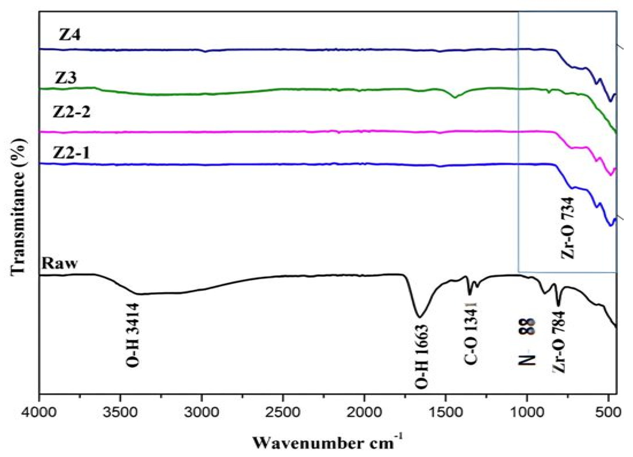
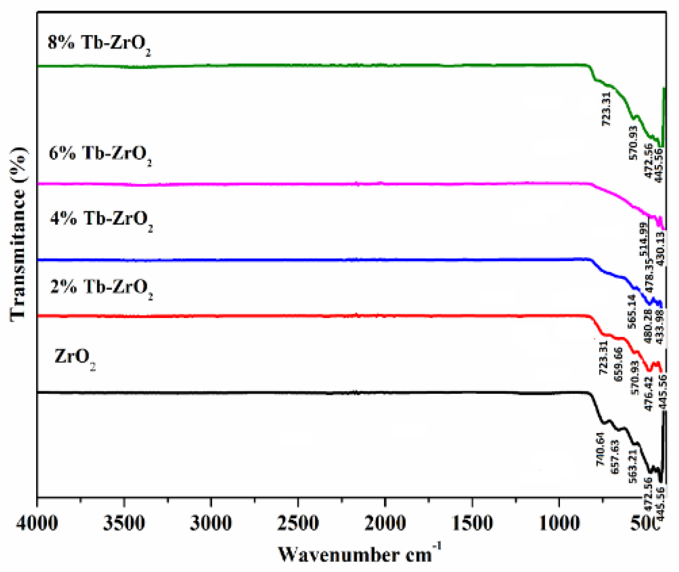
From Figure 1, it is observed that the band 3414 cm−1 describes the stretching vibration of the OH group, and band 1663 cm−1 expresses the bending vibration of the OH group. The stretching and bending were due to the distance between the bonds of two atoms that can be caused by vibration and angle of the bond due to vibration, respectively. The spectra from Z2-1 to Z4 showed the significant peaks of Zirconia oxide without any existence of carbonate and nitrate peaks. From Figure 2, after stabilizing Zirconia with Terbium, there was no effect in the functional group related to Zirconia. The peaks ranging between 420 and 470 cm−1 outline the stretching mode of Zr-O. The peaks in the range of 700, 501, 470–476, 450, 400 cm−1 define the tetragonal phase of Zirconia [18,19]. This was further evidenced by the XRD pattern.
3.2. XRD Analysis
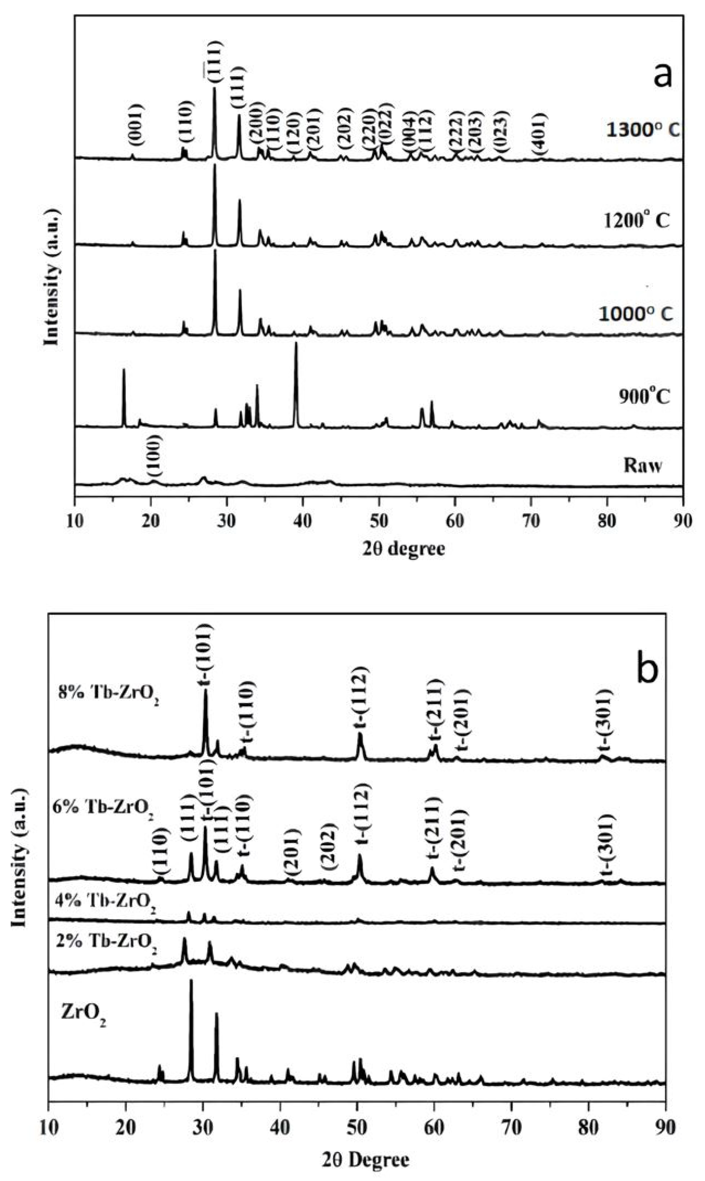
The XRD results of the Zirconia sample showed the monoclinic phase of Zirconia when sintered at 900°, 1000°, 1200°, and 1300 °C. Figure 3a represents the raw peak of XRD analysis performed on an unsintered Zirconia sample. From Figure 3a, the peaks at 2θ = 24.2°, 28.2°, 31.4°, 34.3° were compared to JCPDS file no.37-1484 and confirmed to be the monoclinic phase of Zirconia. The peaks occurring before 2θ = 24.2° are due to the deficiency of oxygen in Zirconium oxide. Figure 3b shows the XRD result, the various concentrations of Terbium doped Zirconia.
It was observed that 2% Tb-Zirconia showed a monoclinic phase with fewer intensity peaks. The 4% Tb-Zirconia showed the slow phase transformation from a monoclinic phase to tetragonal phase. The 6% Tb-Zirconia showed a combination of monoclinic and tetragonal phases of Zirconia. When Zirconia was doped with 8% Terbium, peaks at 2θ = 30.2°, 35.2°, 50.6°, and 60.2° were observed, which was confirmed as a tetragonal phase of Zirconia through JCPDS file no. 80-0965. Therefore, the Tetragonal phase of Zirconia was stabilized, as it has mechanical properties to offer.
3.3. FE-SEM
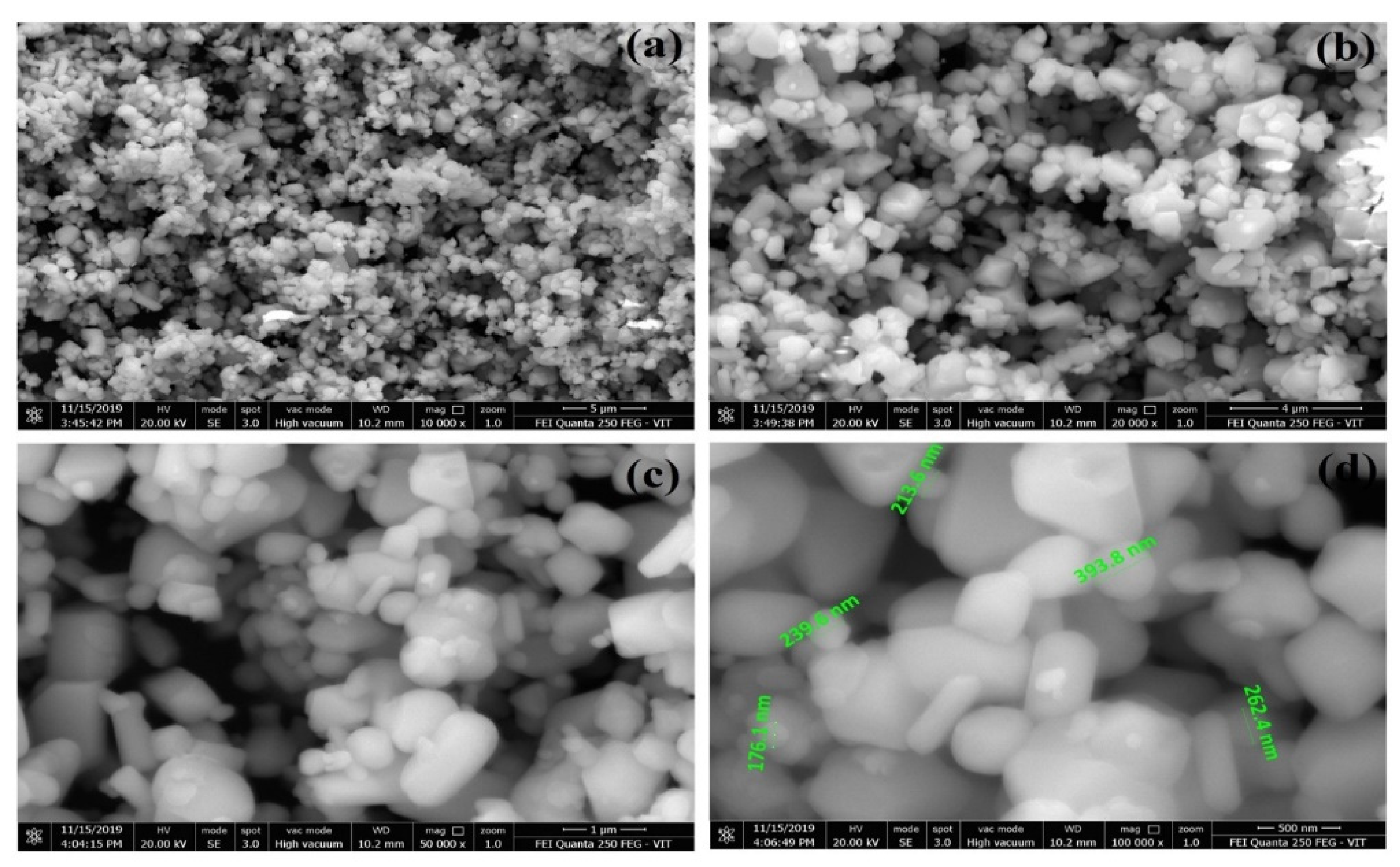
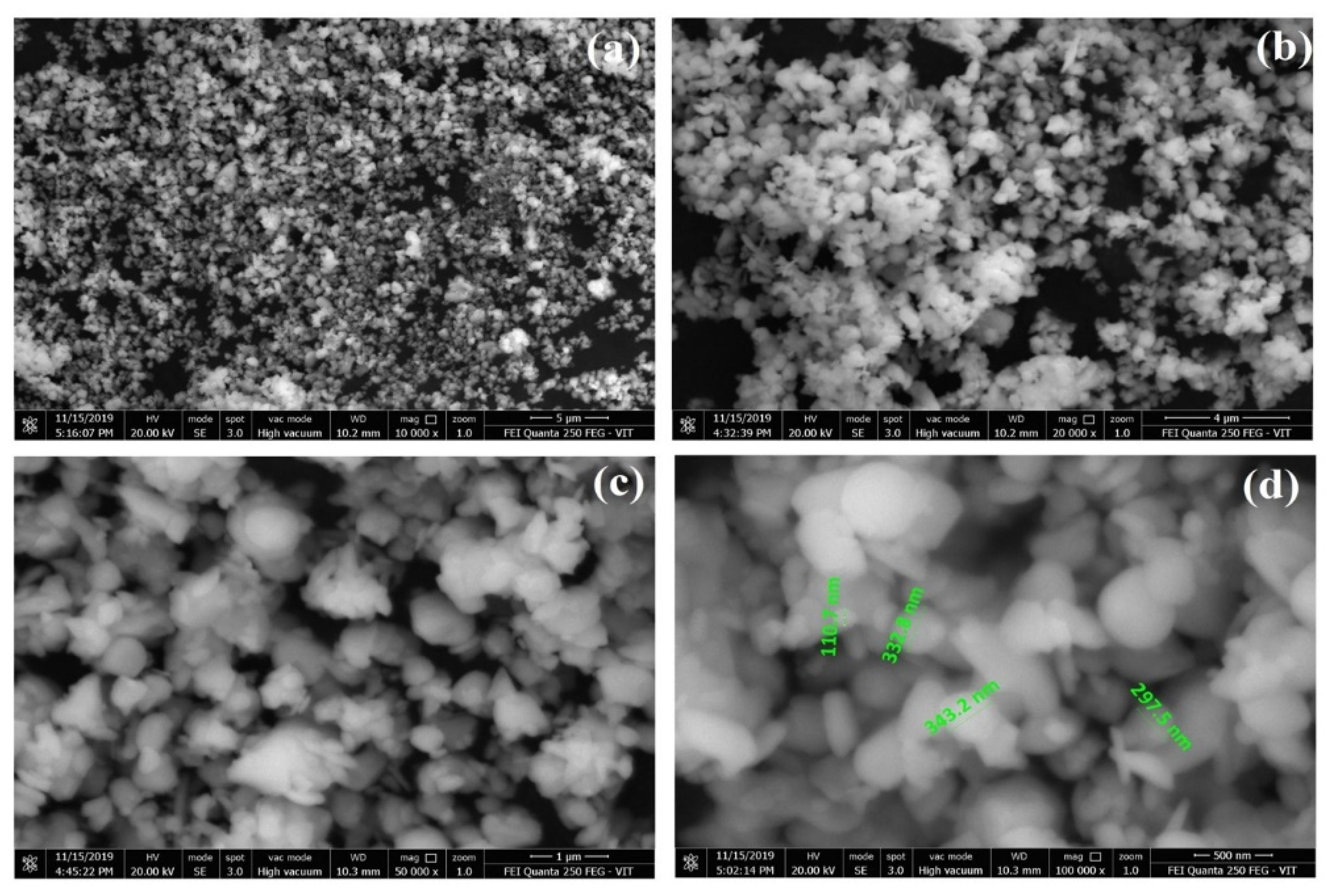
FE-SEM provides a greater magnification with good resolution at lower accelerating voltages. From Figure 4, it was observed that particles existed in a cylindrical shape and their size ranged between 176 nm and 393 nm. From Figure 5, the particles were observed to exist in a spherical shape, and the particle size ranged between 110 nm and 343 nm. The range of particle size was observed to be less in Terbium doped Zirconia when compared to undoped Zirconia. Particle size ranging in nanoscale, has an advantage in drug delivery, has greater effective surfaces and generally promotes the growth of the bone cells, and affects the resorption rate. Particle agglomeration was observed, which was because of the collision of particles during the stirring and aging procedures. Figure 5c shows clouding, which was seen as one particle surrounded by another, which in turn indicates that Terbium has been successfully doped into Zirconium.
3.4. TEM
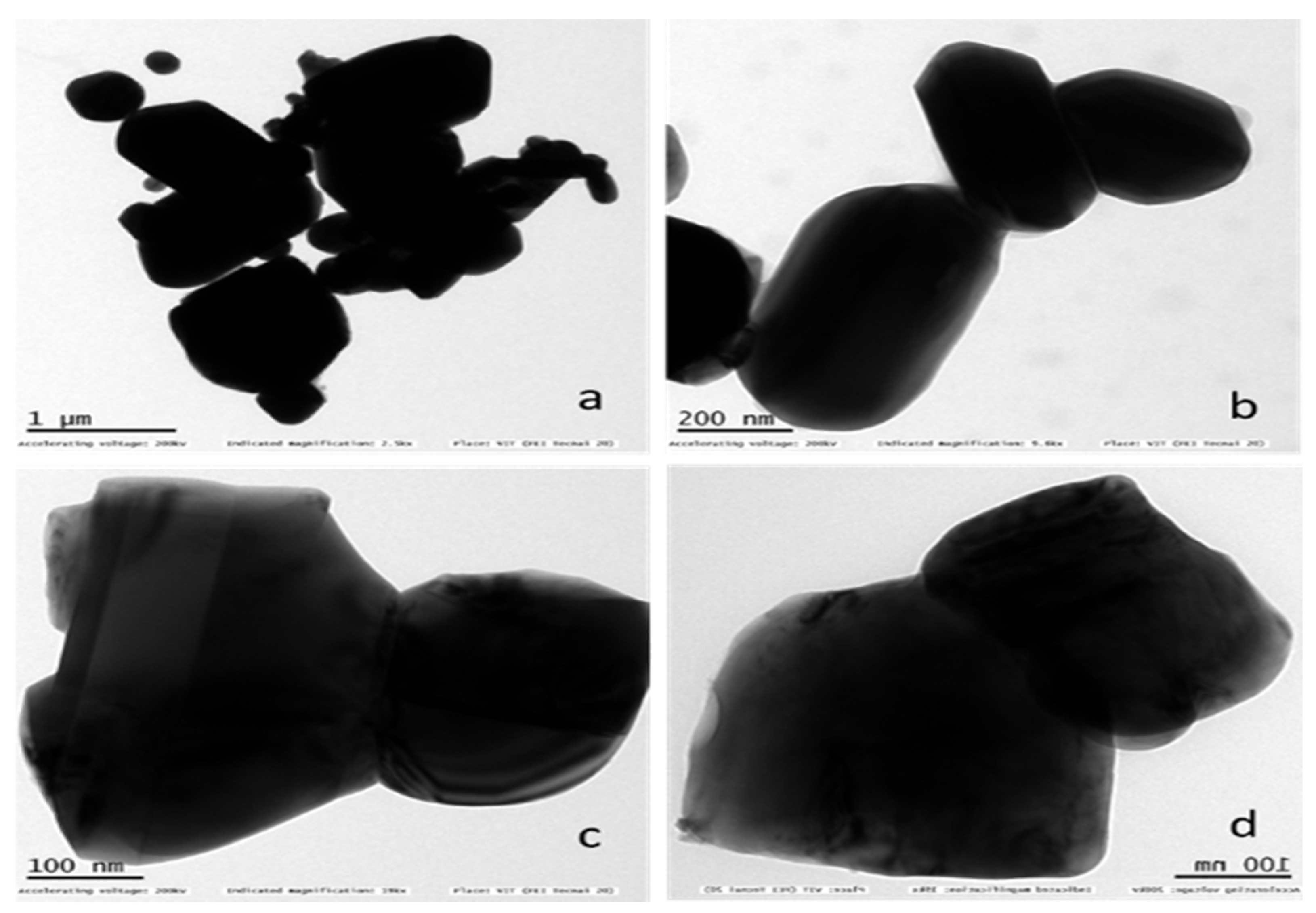
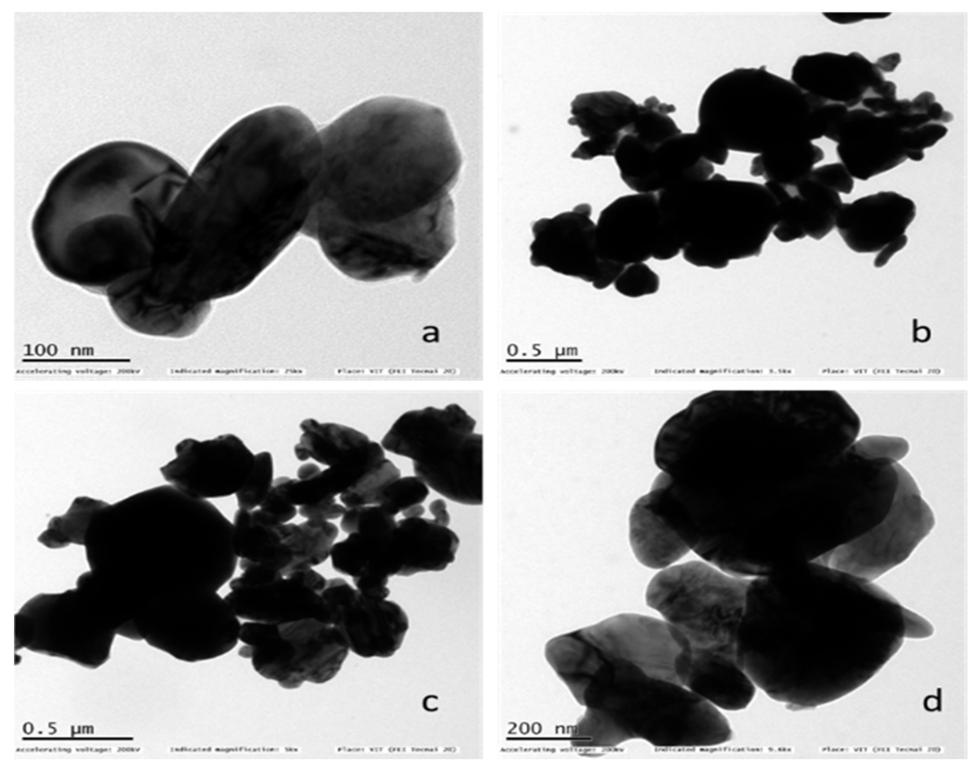
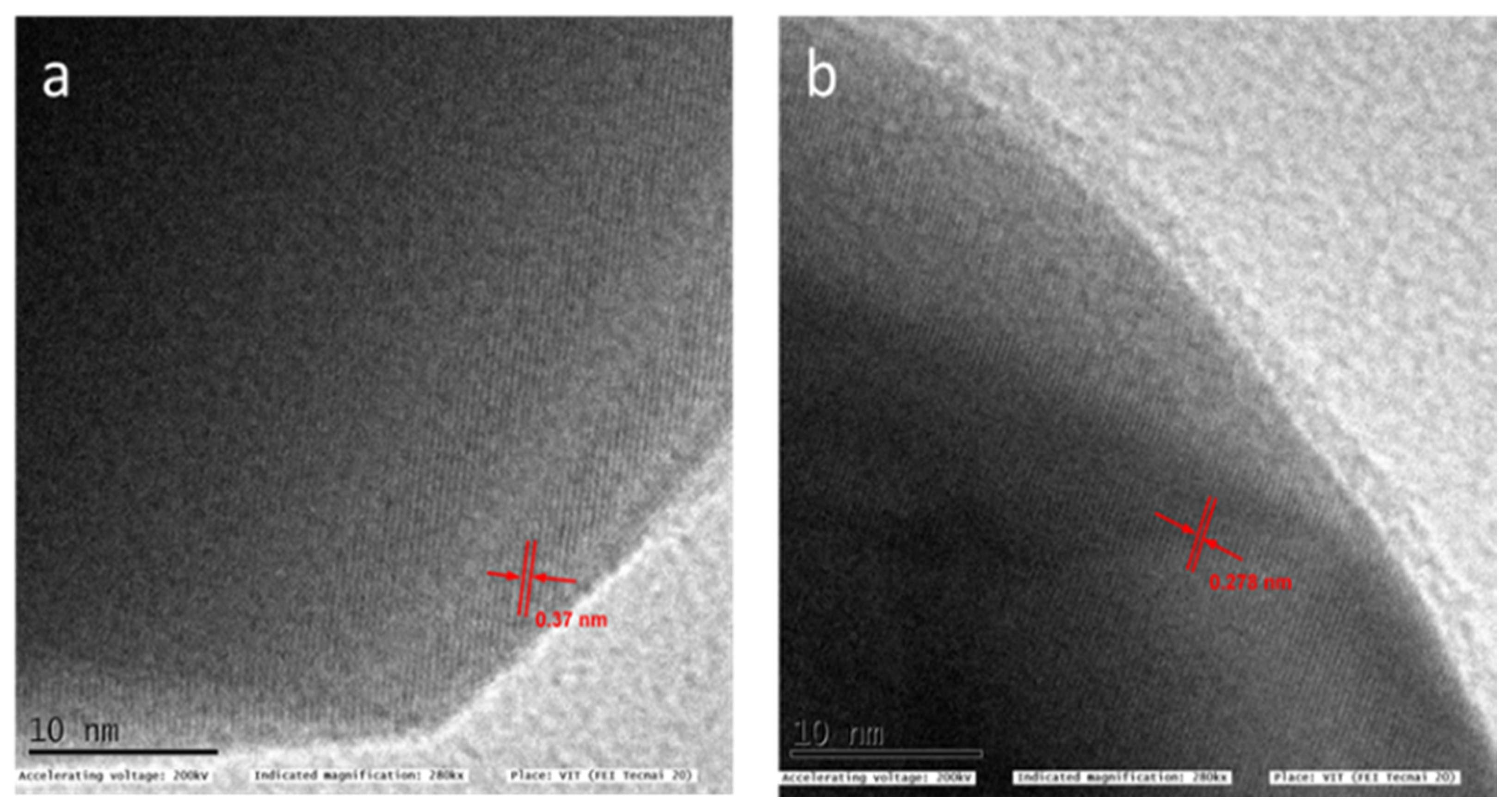
TEM images portrayed a greater magnification, where the structural details of the samples were studied. From Figure 6, the diffraction was different for different regions and orientations of the crystal, and thus, there arose a difference in diffraction contrast. The contrast observed was because of the spherical-shaped particles wherein the electrons have to travel short distances at the edges, so, it was brighter at the edges, whereas the electrons had to take a longer path, so, it was darker towards the center of the particle. The particles were observed to be in spherical and rod shapes. From Figure 7, there was agglomeration observed and the spherical Zirconia particles were observed to be clouded by the Terbium particles. From Figure 8a,b, the distance ‘d’ between two layers of undoped and doped sample crystals was observed to be 0.37 nm and 0.278 nm, respectively. The distance between the two layers was comparatively less in the doped sample. Thus, the obtained ‘d’ was used to calculate Bragg’s equation, which explains the relationship of reflected X-rays from the surface of the crystal.
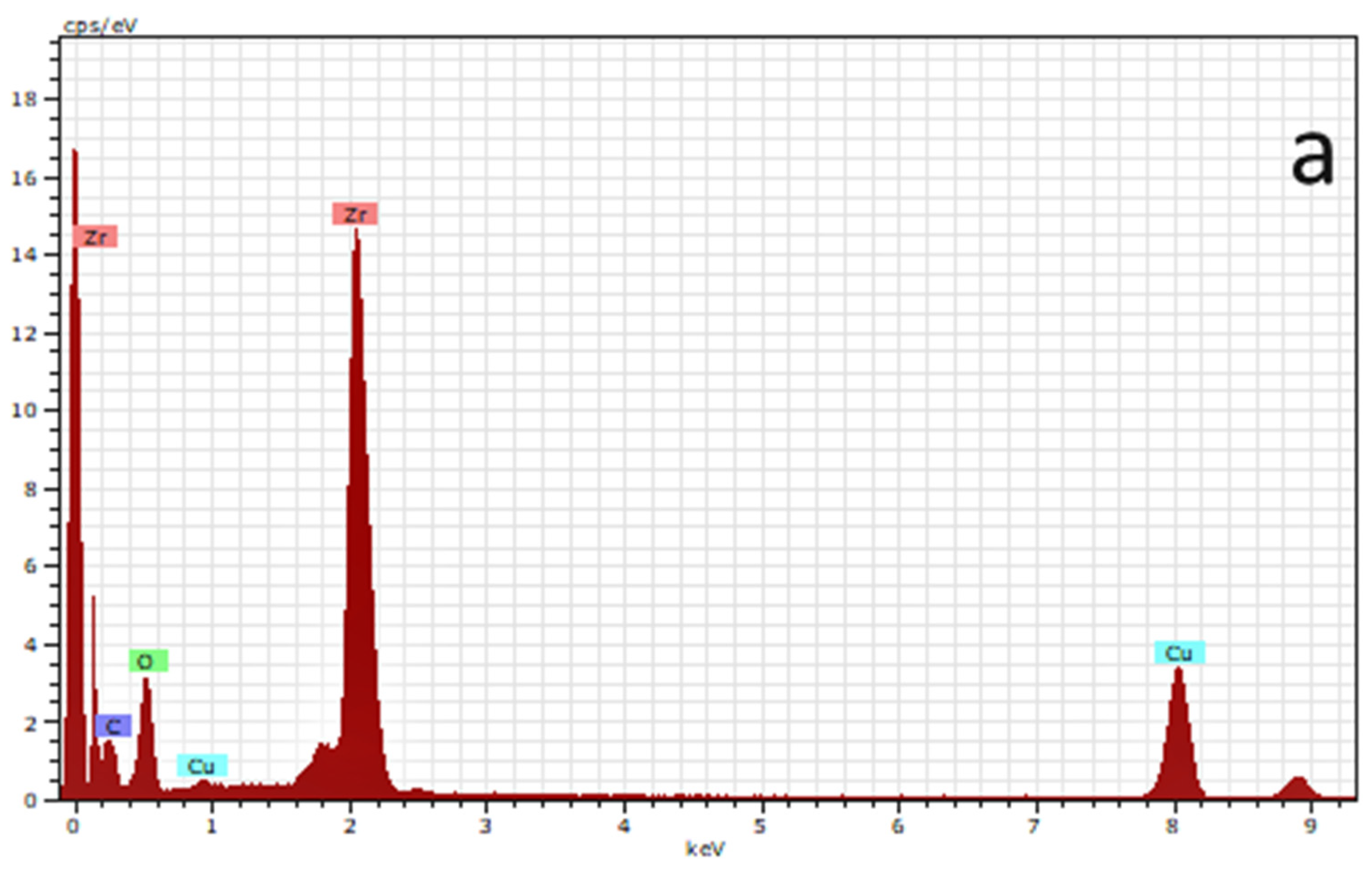
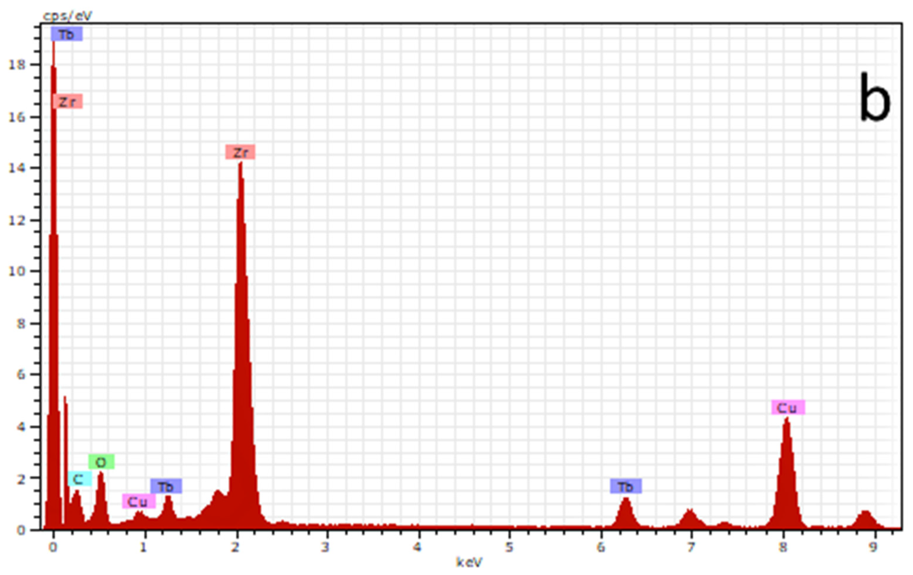
From Figure 9a, the EDAX of the Zirconia sample showed Zirconia and O peaks. EDAX of the 8% Terbium doped Zirconia showed both Zirconia and Terbium peaks. Zirconia peaks were designated together with Tb and O peaks as observed in Figure 9b. The appearance of Cu peaks is the result of the copper grid. C peaks are the results of a carbon-coated copper grid. No other peaks were evident from the figures indicating that the composition was pure.
3.5. Photoluminescence Property
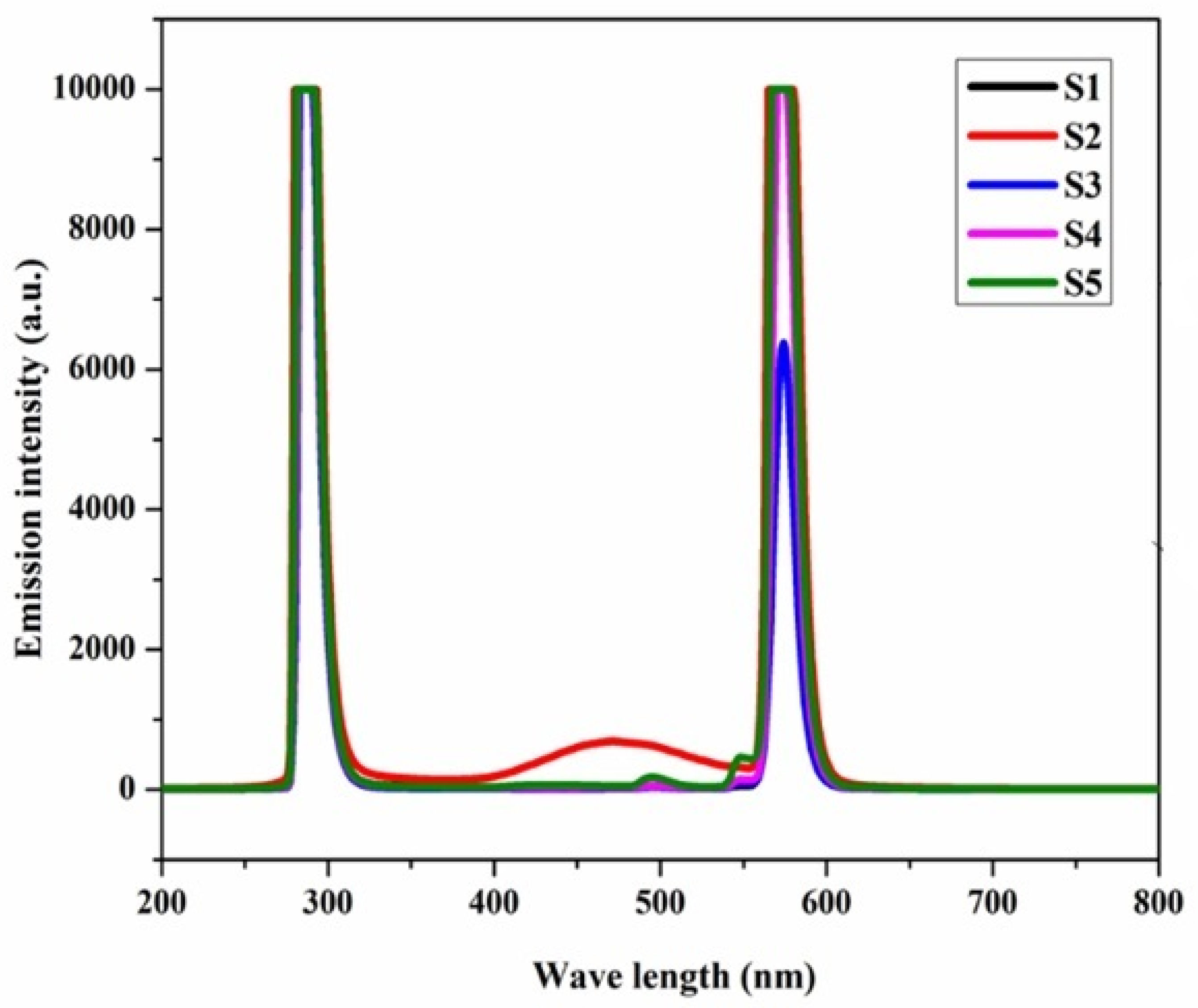
Figure 10 shows the results obtained after performing fluorescent spectroscopy on Zirconia and Terbium doped Zirconia (2–8%). From Figure 10, the excitation at 285 nm showed emission spectra at 200–280 nm in the Zirconia sample (S1) and all the concentrations of Terbium (S2–S5) [33,34,35]. The emission spectrum was commonly observed at 547 nm for all the compositions from S2 to S4. S1 was observed to have peaks within the ranges of 430.6–472.0 nm, 481.6–495.8 nm, and 512.0–568.8 nm. S2 was observed to have peaks in the range of 366.8–472.2 nm and 553.4–565.2 nm. S3 displayed peaks in the range of 432.8 nm-472.0 nm, 481.2–497.2 nm, 525.6–548.2 nm, and 554.2–570.6 nm. S4 showed peaks at 398.8–440.8 nm, 479.4–494.8 nm, 528.2–548.4 nm, and 555.0–567.2 nm. S5 displayed peaks at 444.8–495.6 nm, 525.8–548.2 nm, and 553.0–574.2 nm. A sudden increase in the intensity of the band was observed in S2, and the intensity decreased with the increase in the Terbium concentration. The transition state of Terbium 5D4 to 7F5 resulted in the emission spectrum ranging between 530 and 560 nm, and 5D4 to 7F6 results in the emission spectrum ranging between 480 and 510 nm [33,34,35].
3.6. Biocompatibility
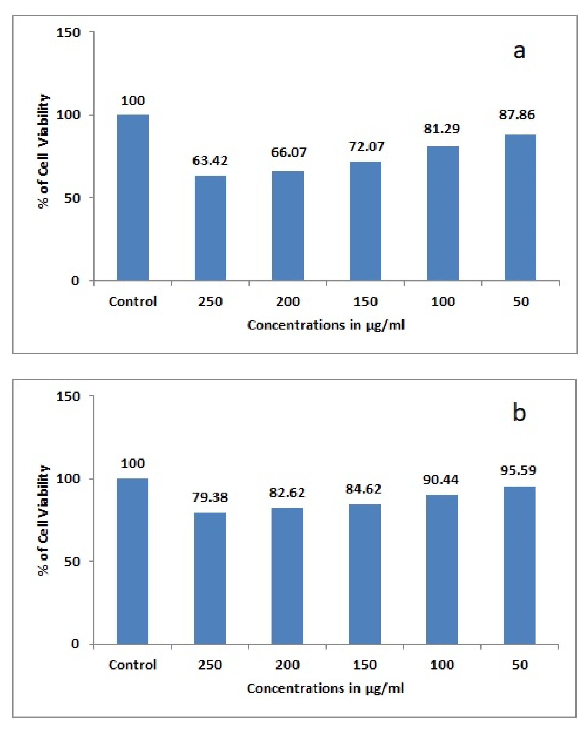
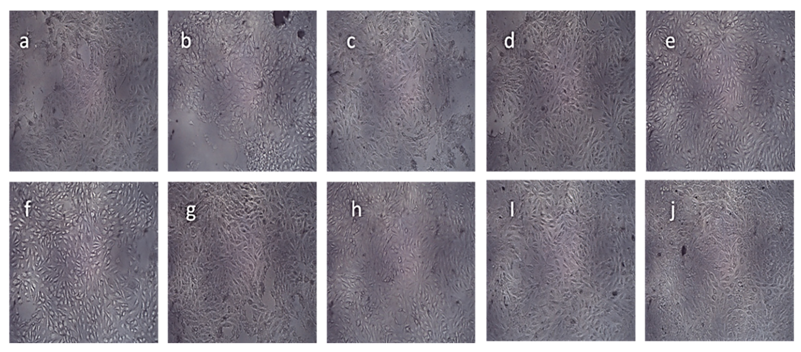
The samples were tested for any possible adverse effects. Graphs were plotted with concentration along the x-axis and percentage of cell viability along the y-axis. From Figure 11a,b, the cell viability decreased as the concentration increased from 50 to 250 µg/mL in both undoped and doped samples. Cell viability was observed to be more in the doped sample at every concentration tested when compared to the undoped sample. Biocompatibility of a material defines whether the implant material releases components into the bodily environment and the cell viability. The biocompatibility of material usually depends on the effect of bodily fluids, force applied, and pH of the surrounding environment. The attachment of host cells or bacterial cells is generally based on the properties of the surface. The composition of the sample, physical form, surface reactivity, and impurities present usually influence the test results [33,34]. From the optical microscopy, Figure 12, showed the presence of both live and dead cells. From Figure 12e, dead cells (spherical shaped cells) were more in the Zirconia sample when compared to the Terbium doped Zirconia sample [35,36,37].
4. Conclusions
In this paper, Zirconia and Terbium doped Zirconia were synthesized using the coprecipitation method and were studied in detail using various characterization techniques. Biological activity was studied on the Mg-63 cell line. The XRD of 8% Tb doped Zirconia showed phase transformation from monoclinic to the tetragonal phase when sintered at 1200 °C for 2 h. There was no possible contamination of other functional groups, and pure Zirconia and Terbium doped Zirconia were observed from FTIR analysis. The microstructural diversities were studied in detail with the help of FE-SEM and TEM and the particle size was seemingly reduced for 8% Terbium doped Zirconia. EDAX showed the presence of a pure form of Zirconia and Terbium doped Zirconia. The biocompatibility test of Zirconia and Terbium doped Zirconia showed that the cell viability of Zirconia was 63.42%, whereas the cell viability of 8%Terbium doped Zirconia was observed to be 79.38%. Therefore, a Terbium doped Zirconia composite can be used for biomedical applications. In addition to the work carried out in this paper, a detailed analysis of the cytocompatibility of Tb doped Zirconia composite samples needs to be determined. The future work on biocompatibility studies will involve the influence of mesenchymal stem cells on Terbium doped Zirconia samples. Antibacterial activity will also be carried out in the future.
Author Contributions
Conceptualization, S.V. and S.R.; methodology, S.V.; software, S.V.; validation, S.R.; formal analysis, S.V.; writing—original draft preparation, S.V.; writing—review and editing, S.R.; visualization, S.V.; supervision, S.R. All authors have read and agreed to the published version of the manuscript.
Funding
This research received no external funding.
Institutional Review Board Statement
Not applicable.
Informed Consent Statement
Not applicable.
Conflicts of Interest
The authors declare no conflict of interest.
References
- Eichler, A. Tetragonal Y-doped zirconia: Structure and ion conductivity. Phys. Rev. B 2001, 64, 174103. [Google Scholar] [CrossRef]
- Shukla, S.; Seal, S. Mechanisms of room temperature metastable tetragonal phase stabilization in zirconia. Int. Mater. Rev. 2005, 50, 45–64. [Google Scholar] [CrossRef]
- Shanmugam, K.; Sahadevan, R. Bioceramics—An Introductory Overview, Fundamental Biomaterials: Ceramics; Elsevier: Amsterdam, The Netherlands, 2018. [Google Scholar]
- Emrullahoglu Abi, C.B. Toughening Mechanisms in Dental Composites, Toughening Mechanisms in Composite Materials; Woodhead Publishing: Philadelphia, PA, USA, 2015. [Google Scholar]
- Matinlinna, J.P. Processing and Bonding of Dental Ceramics, Non-Metallic, Biomaterials for Tooth Repair and Replacement; Woodhead Publishing: Philadelphia, PA, USA, 2013. [Google Scholar]
- Manicone, P.F.; Iommetti, P.R.; Raffaelli, L. An overview of zirconia ceramics: Basic properties and clinical applications. J. Dent. 2007, 35, 819–826. [Google Scholar] [CrossRef] [PubMed]
- Sollazzo, V.; Pezzetti, F.; Scarano, A.; Piattelli, A.; Bignozzi, C.A.; Massari, L.; Brunelli, G.; Carinci, F. Zirconium oxide coating improves implant osseointegration in vivo. Dent. Mater. 2008, 24, 357–361. [Google Scholar] [CrossRef]
- Özkurt, Z.; Kazazoğlu, E. Zirconia Dental Implants: A Literature Review. J. Oral Implantol. 2011, 37, 367–376. [Google Scholar] [CrossRef] [PubMed]
- Gupta, S. A Recent Updates on Zirconia Implants: A Literature Review. J. Dent. Sci. Med. 2016, 1, 18–26. [Google Scholar]
- Chai, J.; Chu, F.C.S.; Chow, T.W.; Liang, B.M.H. Chemical solubility and flexural strength of zirconia-based ceramics. Int. J. Prosthodont. 2007, 20, 587–595. [Google Scholar]
- Kvam, K.; Karlsson, S. Solubility and strength of zirconia-based dental materials after artificial aging. J. Prosthet. Dent. 2013, 110, 281–287. [Google Scholar] [CrossRef]
- Thompson, J.Y.; Stoner, B.R.; Piascik, J.R.; Smith, R. Adhesion/cementation to zirconia and other non-silicate ceramics: Where are we now? Dent. Mater. 2011, 27, 71–82. [Google Scholar] [CrossRef] [Green Version]
- Mulinti, P.; Lervick, B.; Pullan, J.E.; Brooks, A.E. Strategies to improve the hemocompatibility of biodegradable biomaterials. In Hemocompatibility of Biomaterials for Clinical Applications; Woodhead Publishing: Philadelphia, PA, USA, 2018. [Google Scholar]
- Khang, G.; Kim, S.H.; Kim, M.S.; Lee, H.B. Hybrid, Composite, and Complex Biomaterials for Scaffolds; Hybrid, Composite, and Complex Biomaterials for Scaffolds, Principles of Regenerative Medicine; Academic Press: Cambridge, MA, USA, 2008. [Google Scholar]
- Zafar, M.S.; Khurshid, Z.; Najeeb, S.; Zohaib, S.; Rehman, I.U. Therapeutic Applications of Nanotechnology in Dentistry, Nanostructures for Oral Medicine; Elsevier: Amsterdam, The Netherlands, 2017; pp. 833–862. [Google Scholar]
- Al-Amleh, B.; Lyons, K.; Swain, M. Clinical trials in zirconia: A systematic review. J. Oral Rehabil. 2010, 37, 641–652. [Google Scholar] [CrossRef]
- Wong, M.S.; Ying, J.Y. Amphiphilic Templating of Mesostructured Zirconium Oxide. Chem. Mater. 1998, 10, 2067–2077. [Google Scholar] [CrossRef]
- Wang, G.; Liu, X.; Ding, C. Phase composition and in-vitro bioactivity of plasma sprayed calcia stabilized zirconia coatings. Surf. Coat. Technol. 2008, 202, 5824–5831. [Google Scholar] [CrossRef]
- Kelly, J.R.; Denry, I. Stabilized zirconia as a structural ceramic: An overview. Dent. Mater. 2008, 24, 289–298. [Google Scholar] [CrossRef] [PubMed]
- Hsu, Y.-W.; Yang, K.-H.; Chang, K.-M.; Yeh, S.-W.; Wang, M.-C. Synthesis and crystallization behavior of 3mol% yttria stabilized tetragonal zirconia polycrystals (3Y-TZP) nanosized powders prepared using a simple co-precipitation process. J. Alloys Compd. 2011, 509, 6864–6870. [Google Scholar] [CrossRef]
- Benzaid, R.; Chevalier, J.; Saâdaoui, M.; Fantozzi, G.; Nawa, M.; Diaz, L.A.; Torrecillas, R. Fracture toughness, strength and slow crack growth in a ceria stabilized zirconia–alumina nanocomposite for medical applications. Biomaterials 2008, 29, 3636–3641. [Google Scholar] [CrossRef] [PubMed]
- Liu, X.; Huang, A.; Ding, C.; Chu, P.K. Bioactivity and cytocompatibility of zirconia (ZrO2) films fabricated by cathodic arc deposition. Biomaterials 2006, 27, 3904–3911. [Google Scholar] [CrossRef] [PubMed]
- Ebnesajjad, S.; Ebnesajjad, C. Surface Treatment and Bonding of CeramicsSurface Treatment of Materials for Adhesive Bonding, 2nd ed.; Elsivier: Singapore, 2013. [Google Scholar]
- Huang, H.-L.; Chang, Y.-Y.; Chen, Y.-C.; Lai, C.-H.; Chen, M.Y. Cytocompatibility and antibacterial properties of zirconia coatings with different silver contents on titanium. Thin Solid Films 2013, 549, 108–116. [Google Scholar] [CrossRef]
- Han, Y.; Yan, Y.; Lu, C. Ultraviolet-enhanced bioactivity of ZrO2 films prepared by micro-arc oxidation. Thin Solid Films 2009, 517, 1577–1581. [Google Scholar] [CrossRef]
- Afzal, A. Implantable zirconia bioceramics for bone repair and replacement: A chronological review. Mater. Express 2014, 4, 1–12. [Google Scholar] [CrossRef]
- Cho, Y.; Hong, J.; Ryoo, H.; Kim, D.; Park, J.; Han, J. Osteogenic Responses to Zirconia with Hydroxyapatite Coating by Aerosol Deposition. J. Dent. Res. 2015, 94, 491–499. [Google Scholar] [CrossRef] [Green Version]
- Vijayalakshmi, U.; Prabakaran, K.; Rajeswari, S. Preparation and characterization of sol-gel hydroxyapatite and its electrochemical evaluation for biomedical applications. J. Biomed. Mater. Res. Part A 2008, 87A, 739–749. [Google Scholar] [CrossRef]
- Natarajan, U.V.; Rajeswari, S. Influence of calcium precursors on the morphology and crystallinity of sol–gel-derived hydroxyapatite nanoparticles. J. Cryst. Growth 2008, 310, 4601–4611. [Google Scholar] [CrossRef]
- Kaszewski, J.; Borgstrom, E.; Witkowski, B.; Wachnicki, Ł.; Kiełbik, P.; Slonska, A.; Domino, M.; Narkiewicz, U.; Gajewski, Z.; Hochepied, J.-F. Terbium content affects the luminescence properties of ZrO2:Tb nanoparticles for mammary cancer imaging in mice. Opt. Mater. 2017, 74, 16–26. [Google Scholar] [CrossRef]
- Navarro, M.; Michiardi, A.; Castano, O.; Planell, J. Biomaterials in orthopedics. J. R. Soc. Interface 2008, 5, 1137–1158. [Google Scholar] [CrossRef] [Green Version]
- Chambers, M.; Clarke, D. Terbium as an alternative for luminescence sensing of temperature of thermal barrier coating materials. Surf. Coatings Technol. 2007, 202, 688–692. [Google Scholar] [CrossRef]
- James, M. Anderson, Biocompatibility and Bioresponse to Biomaterials, Principles of Regenerative Medicine; Academic Press: Cambridge, MA, USA, 2008. [Google Scholar]
- Ahmed, M.H.; Byrne, J.A.; Keyes, T.E.; Ahmed, W.; Elhissi, A.; Jackson, M.J.; Ahmed, E. Characteristics and applications of titanium oxide as a biomaterial for medical implants. In The Design and Manufacture of Medical Devices; Woodhead Publishing Reviews: Mechanical Engineering Series; Woodhead Publishing: Sawston, UK, 2012. [Google Scholar]
- Zawadzki, M.; Hreniak, D.; Wrzyszcz, J.; Mista, W.; Grabowska, H.; Malta, O.; Stręk, W. Photoluminescence and cathodoluminescence of Tb-doped Al2O3–ZrO2 nanostructures obtained by sol–gel method. Chem. Phys. 2003, 291, 275–285. [Google Scholar] [CrossRef]
- Ponnilavan, V.; Khan, M.I.K.; Dhayalan, A.; Kannan, S. Structure, luminescence, mechanical and in vitro behavior of zirconia toughened alumina due to Terbium substitutions. Mater. Sci. Eng. C 2019, 102, 810–819. [Google Scholar] [CrossRef] [PubMed]
- Hardin, C.L.; Kodera, Y.; Basun, S.A.; Evans, D.R.; Garay, J.E. Transparent, luminescent Terbium doped zirconia: Development of optical-structural ceramics with integrated temperature measurement functionalities. Opt. Mater. Express 2013, 3, 893–903. [Google Scholar] [CrossRef]
Figure 1.
FTIR of Zirconia.

Figure 2.
FTIR of Terbium doped Zirconia.

Figure 3.
(a) XRD of Zirconia and (b) XRD of Terbium doped Zirconia.

Figure 4.
FE-SEM of Zirconia with magnification at different scales (a) 5 µm, (b) 4 µm, (c) 1 µm, and (d) 500 nm.
Figure 4.
FE-SEM of Zirconia with magnification at different scales (a) 5 µm, (b) 4 µm, (c) 1 µm, and (d) 500 nm.

Figure 5.
FE-SEM of Terbium doped Zirconia with magnification at different scales (a) 5 µm, (b) 4 µm, (c) 1 µm, and (d) 500 nm.
Figure 5.
FE-SEM of Terbium doped Zirconia with magnification at different scales (a) 5 µm, (b) 4 µm, (c) 1 µm, and (d) 500 nm.

Figure 6.
TEM images of Zirconia at different scales (a) 1 µm, (b) 200 nm, (c) 100 nm, and (d) 1 nm.
Figure 6.
TEM images of Zirconia at different scales (a) 1 µm, (b) 200 nm, (c) 100 nm, and (d) 1 nm.

Figure 7.
TEM images of Terbium doped Zirconia at different scales (a) 100 mm, (b) 5 µm, (c) 0.5 µm, and (d) 200 nm.
Figure 7.
TEM images of Terbium doped Zirconia at different scales (a) 100 mm, (b) 5 µm, (c) 0.5 µm, and (d) 200 nm.

Figure 8.
TEM images with distance ‘d’ between two layers of the particle of (a) Zirconia and (b) Terbium doped Zirconia.
Figure 8.
TEM images with distance ‘d’ between two layers of the particle of (a) Zirconia and (b) Terbium doped Zirconia.

Figure 9.
(a) EDAX of Zirconia, (b) EDAX of Terbium doped Zirconia (8%).


Figure 10.
Photoluminescence spectra S1- Zirconia, S2- 2%Tb doped Zirconia, S3- 4%Tb doped Zirconia, S4- 6%Tb doped Zirconia, and S5- 8%Tb doped Zirconia.
Figure 10.
Photoluminescence spectra S1- Zirconia, S2- 2%Tb doped Zirconia, S3- 4%Tb doped Zirconia, S4- 6%Tb doped Zirconia, and S5- 8%Tb doped Zirconia.

Figure 11.
(a): Cytotoxicity study of Zirconia and (b): Cytotoxicity study of Terbium doped Zirconia.
Figure 11.
(a): Cytotoxicity study of Zirconia and (b): Cytotoxicity study of Terbium doped Zirconia.

Figure 12.
Optical microscopy of cytotoxicity studies (a–e) Zirconia, (f–j) Terbium doped Zirconia. (a,f) 250 µg/mL, (b,g) 200 µg/mL, (c,h) 150 µg/mL, (d,i) 100 µg/mL, and (e,j) 50 µg/mL.
Figure 12.
Optical microscopy of cytotoxicity studies (a–e) Zirconia, (f–j) Terbium doped Zirconia. (a,f) 250 µg/mL, (b,g) 200 µg/mL, (c,h) 150 µg/mL, (d,i) 100 µg/mL, and (e,j) 50 µg/mL.

Publisher’s Note: MDPI stays neutral with regard to jurisdictional claims in published maps and institutional affiliations. |
© 2022 by the authors. Licensee MDPI, Basel, Switzerland. This article is an open access article distributed under the terms and conditions of the Creative Commons Attribution (CC BY) license (https://creativecommons.org/licenses/by/4.0/).
Share and Cite
MDPI and ACS Style
Veerachamy, S.; Rajagopal, S. Microstructural Analysis of Terbium Doped Zirconia and Its Biological Studies. Condens. Matter 2022, 7, 20. https://0-doi-org.brum.beds.ac.uk/10.3390/condmat7010020
AMA Style
Veerachamy S, Rajagopal S. Microstructural Analysis of Terbium Doped Zirconia and Its Biological Studies. Condensed Matter. 2022; 7(1):20. https://0-doi-org.brum.beds.ac.uk/10.3390/condmat7010020
Chicago/Turabian StyleVeerachamy, Suganthan, and Sivakumar Rajagopal. 2022. "Microstructural Analysis of Terbium Doped Zirconia and Its Biological Studies" Condensed Matter 7, no. 1: 20. https://0-doi-org.brum.beds.ac.uk/10.3390/condmat7010020