Article

Characterization and Performance Analysis of BST-Based Ferroelectric Varactors in the Millimeter-Wave Domain

1
XLIM, UMR CNRS 7252, University of Limoges, 123 Avenue Albert Thomas, 87060 Limoges, France
2
IETR, UMR CNRS 6164, University of Nantes, 2 rue de la Houssinière, 44322 Nantes CEDEX 3, France
*
Authors to whom correspondence should be addressed.
Submission received: 13 February 2021 / Revised: 28 February 2021 / Accepted: 9 March 2021 / Published: 11 March 2021
(This article belongs to the Special Issue Ferroelectrics Materials for Microwave Devices)

Abstract

:
We present the realization and analysis of the microwave performances of interdigited varactors integrating thin ferroelectric layers of barium and strontium titanate ( Ba x Sr 1 x TiO 3 ). Devices based on ferroelectric films of different compositions (x = 0.8 and x = 0.5) have been characterized in the millimeter-wave domain, from 200   MHz to 110   GHz . By applying different bias voltages, the tunability of the capacitance can reach up to 40% for the Ba 0.8 Sr 0.2 TiO 3 composition, under relatively low applied electric fields of about 167   kV / cm . These promising characteristics allow the integration of the varactor devices in tunable antennas for a large frequency domain, from the microwaves to the millimeter waves range.

1. Introduction

Nowadays, the main challenge in the field of radiofrequencies (RF) telecommunication is the reconfiguration of the subsystems and devices within the RF-front-ends, induced by the multiplication and diversity of the telecommunication standards [1]. For this reason, significant attention is given to agile materials which are able to modify their overall properties (conductivity, permittivity or permeability) under different stimuli and hence may perform a specific function (switching, capacitance variation etc.) [2]. In particular, ferroelectric materials, which have the capability to modify their dielectric constant under a continuous electric field [3], are of great interest in the development of tunable capacitors, which are the basic elements of many reconfigurable devices such as phase shifters [4,5], filters [6], or reconfigurable antennas [7,8,9,10]. Moreover, ferroelectrics offer better power handling capabilities than semi-conductors, which suffer from non-linearity, a better response time than micro-electro-mechanical devices (MEMS), and a low power consumption [11]. In addition to the multiplication of telecommunication standards, the congestion of telecommunication channels (the scarcity of the available frequency bands) leads to the development of devices operating at higher frequencies, in the millimetre-waves domain. Although ferroelectric materials operating at frequencies higher than 30 GHz are under-documented, the limited available data report that they can provide low dielectric losses and sufficient capacitance variation for practical integration in millimetre-waves devices [12].
Different ferroelectrics were investigated in the literature [12,13,14] but barium and strontium titanate, BaxSr1−xTiO3 (BST) remains one of the most studied compounds since, among others ferroelectrics, it presents low dielectric losses and one of the largest permittivity variation under applied direct current (dc) bias. The intrinsic dielectric characteristics of the BST material (the Curie temperature defining the particular ferroelectric or paraelectric state of the material at a given temperature, the material losses, the amplitude of permittivity variation under a given bias field) are related to its composition (i.e., the Ba/Sr ratio) and geometry [15,16].
Two main topologies for the integration of ferroelectrics in capacitor devices are reported in the literature [17]. The first is based on the metal-insulator-metal (MIM) topology [18,19] in which the ferroelectric layer is integrated between two parallel conductive plates (electrodes), allowing a large field concentration into the active layer, and hence important tuning of the capacitance value. The main drawback of this architecture is the use of overlapped layers, which makes the ferroelectric layer performances dependent on the lower electrode quality, and brings complexity to the fabrication process [20] and which are prone to resonant electrostrictive effects [21]. The second topology is planar, less complex, and consists of an inter-digitated capacitor (IDC) metallic structure [22,23,24] build directly on top of the ferroelectric layer. However, due to the limited resolution when using classical microfabrication technology based on optical photolithography, for a similar bias voltage the induced electric field in the BST layer in the case of the IDC device cannot be as high as for the MIM-based topology. Thus higher DC voltages are required in order to obtain similar capacitance variation. The choice between the two topologies and associated performances (losses, capacitance values, agility) depends on the intended application and the frequency domain.
Here we report on the performances of IDC devices fabricated using two different BST compositions and recorded on a wide frequency range, from 200 MHz to 110 GHz, spanning the microwaves and millimetre-wave domains. The permittivity and the intrinsic losses of the BST thin films were deduced by comparing the experimental results with full-wave electromagnetic simulations of the IDC devices. We show the composition-dependent properties of the ferroelectric films (capacitance values, tunability and losses) and demonstrate that BST-based devices can operate in the millimetre-wave domain, up to 110 GHz, with very good performances.

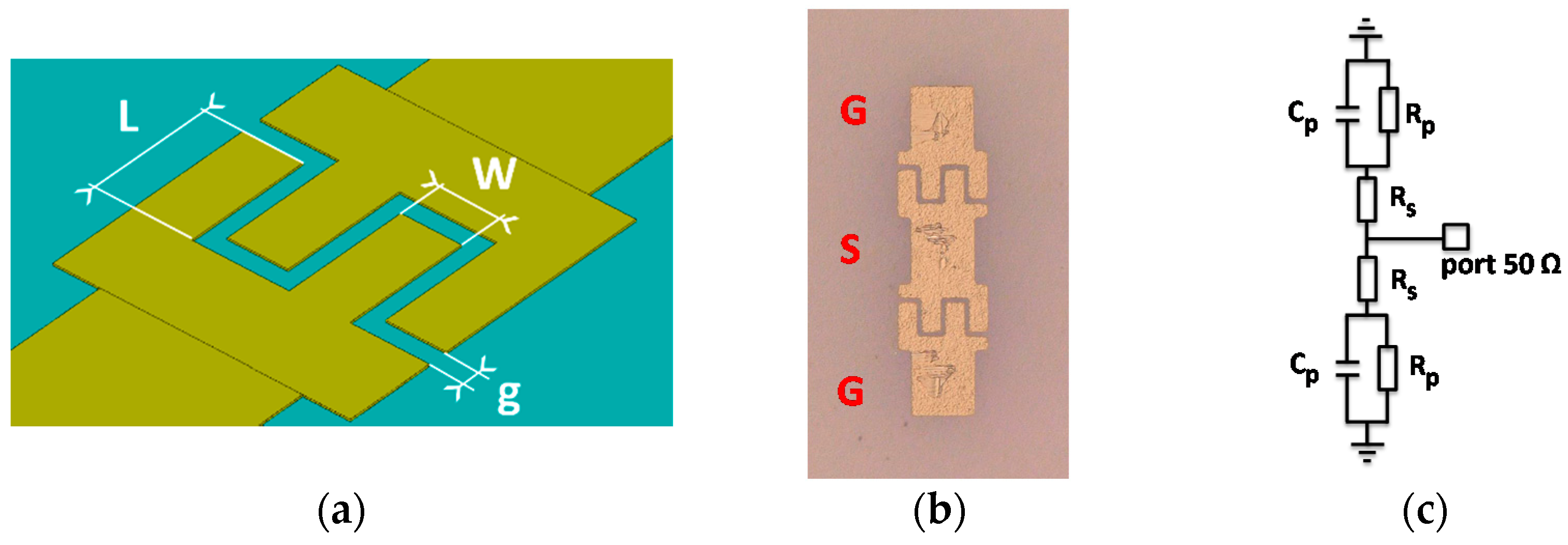
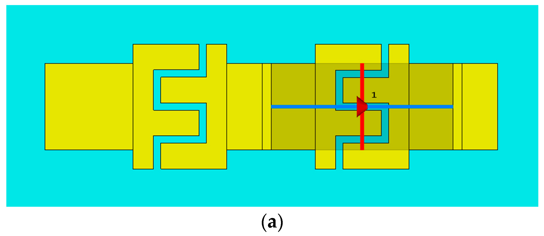
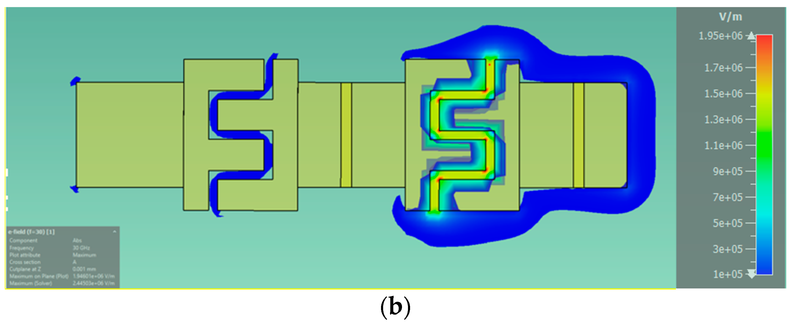
2. Realization and Characterization of BaxSr1−xTiO3 (BST)-Based Inter-Digitated Capacitor (IDC) Varactors

We have prepared two different compositions of Ba x Sr 1 x TiO 3 thin films ( x = 0.8 –BST 80–20 and x = 0.5 –BST 50–50) on alumina substrates with an overall thickness of 860 nm with a modified sol-gel technique and multiple spin-coating [25]. IDC devices have been realized on both BST compositions by means of classical cleanroom micro-fabrication methods (using negative photoresist and lift-off method in order to define the metallic electrodes’ structure and thermal evaporation for the realization of the metallization (Ti/Au, 10/600 nm). The overall topology includes two parallel planar IDC varactors (sharing a common electrode in the middle) in order to facilitate the microwave measurements using GSG (ground-signal-ground) RF probes (Figure 1a,b). A typical investigated device consists of two parallel pairs of electrodes of width w = 20   µ m , length L = 30   µ m and distance between electrodes g = 6   µ m . An optical microscopy image of the fabricated IDC varactor is presented in Figure 1b.
High frequency broadband characterization of the fabricated IDC ferroelectric devices, based on the reflection coefficient measurement, was performed in the range [200 MHz–65 GHz] using a GSG probe connected to a vectorial network analyser (ZVA Rohde and Schwarz). Alternatively, for the [70–110 GHz] frequency band measurements, we used a PM8 Cascade Microtech station, and a Keysight PNA-X N5247B 10 MHz–67 GHz vectorial network analyzer with VDI 70–110 mm waves extension modules and a I110S GSG 100 BT probe. The DC bias voltage (from 0 to 80 V) has been applied on the IDC devices via a bias tee upstream the GSG probe. The DC bias voltage is therefore applied between the ground and the signal electrodes of the probes for the two measured frequency bands (Figure 1b).
The equivalent electric circuit of the overall device is presented in Figure 1c (two IDC devices in parallel), with C p the capacitance of the IDC varactor, in parallel with a resistor R p representing the dielectric losses in the BST films, the whole in series with a resistor R s , modelling ohmic losses in the electrodes. This simple model allows the values of resistance and reactance of the impedance Z 11 of the IDC to be extracted from the measured reflection S 11 parameter values, using Equations (1)–(3):
Z 11 =   Z 0 1 + S 11 1 S 11
Z 11 = R p ( R p C p ω ) ² + 1 + R s j R p 2 C p ω ( R p C p ω ) 2 + 1
1 R p ( C p ω ) 2 + R s j 1 C p ω   =   Z R + j Z I
Considering R p C p ω 1 , the frequency dependence of the capacitance values can be extracted from the imaginary part Z I of the measured Z 11 , while the overall losses of the device are given by ZR.

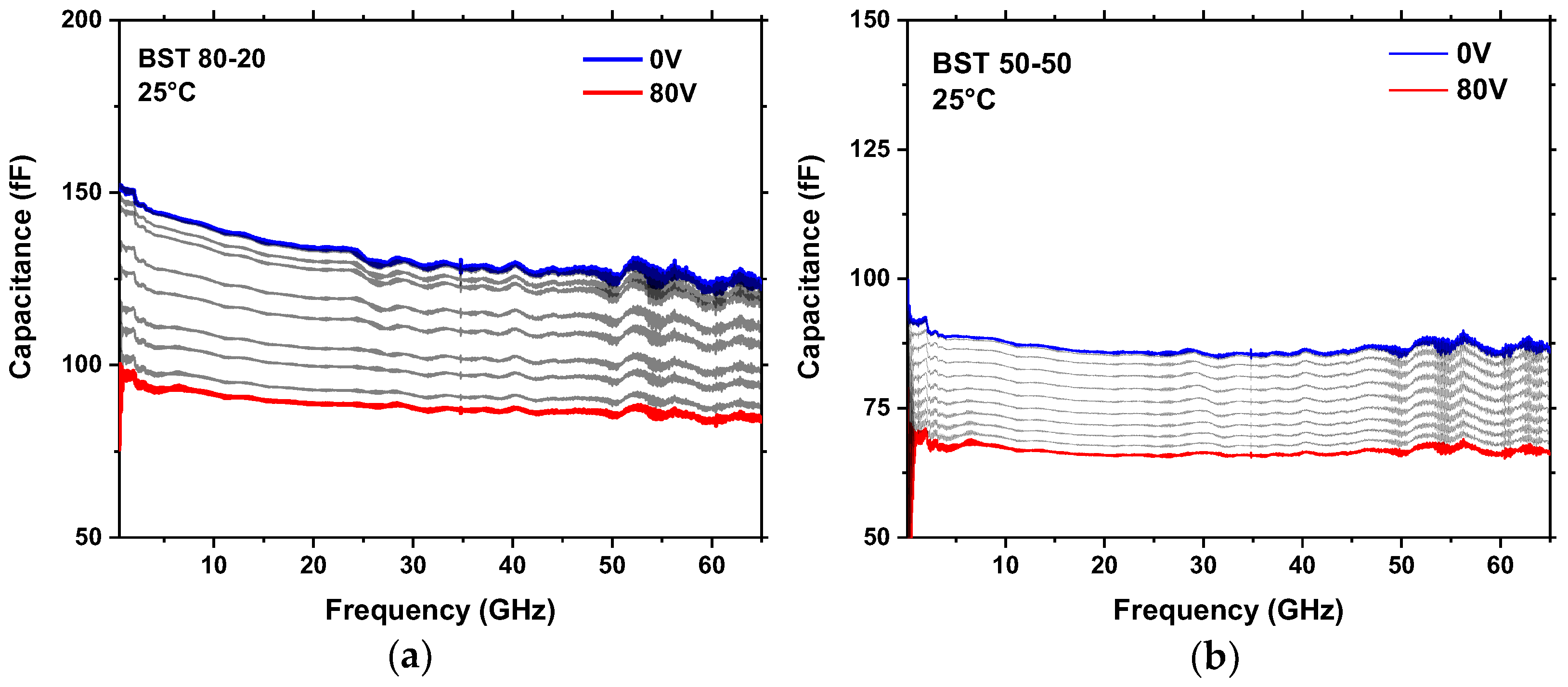
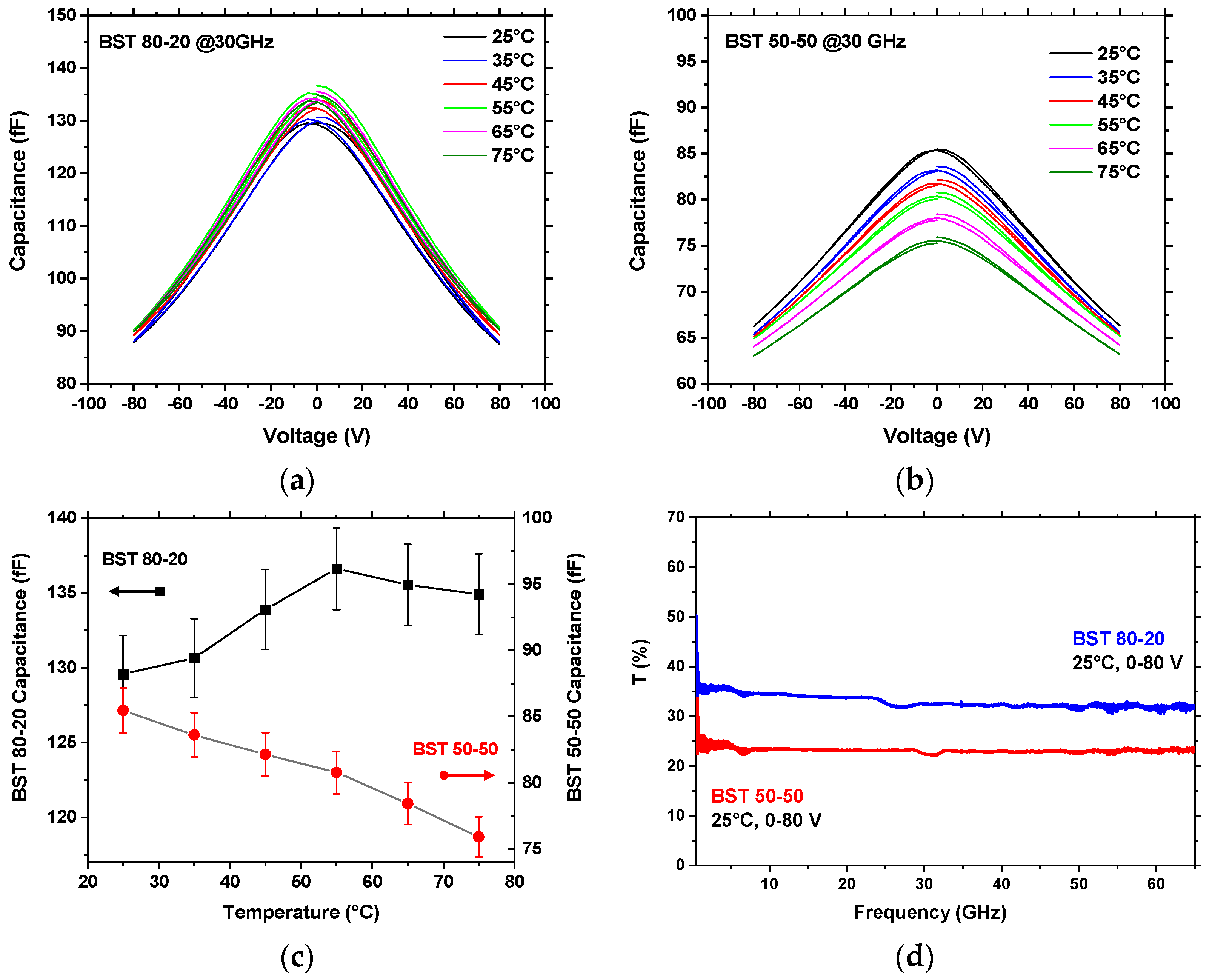
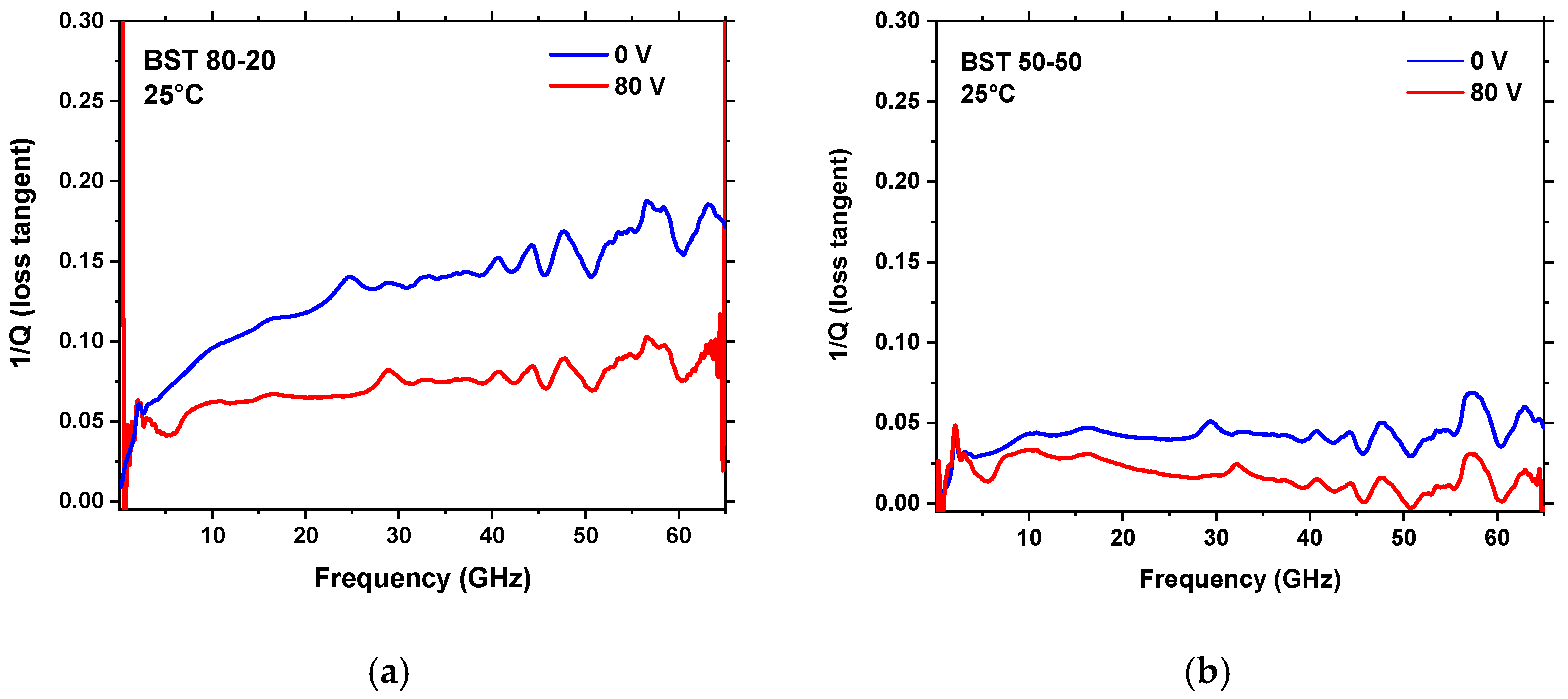
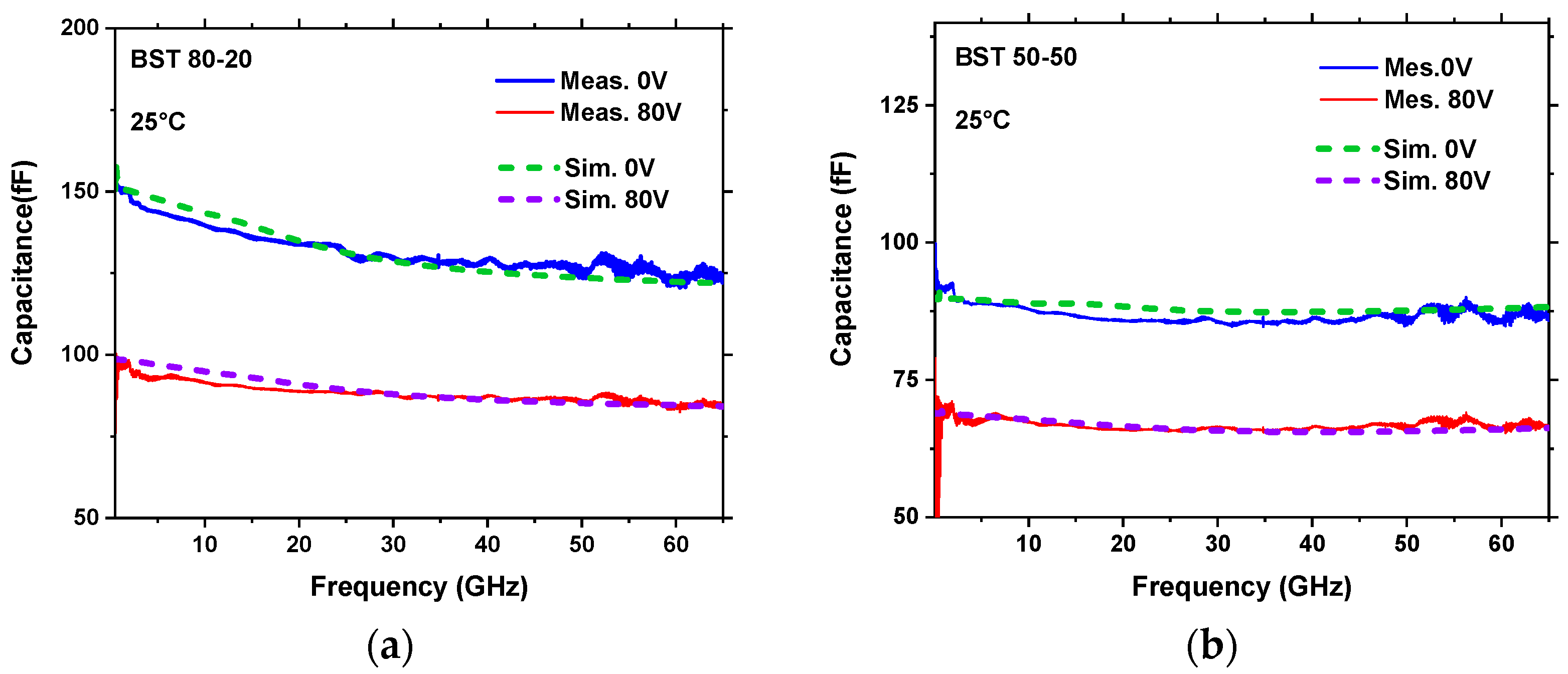
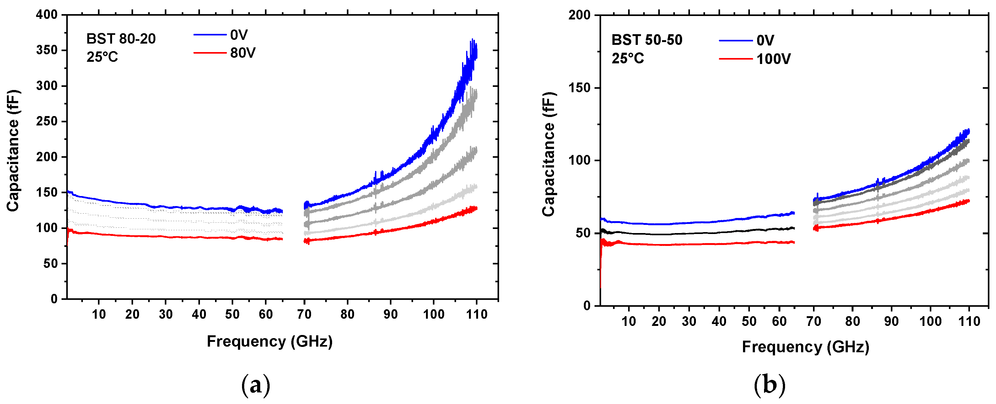
3. Results and Discussion

The frequency dependence of the capacitance C p is shown in Figure 2a,b in the 200 MHz–65 GHz domain for different DC bias voltages between 0 and 80 V, for the composition BST 80–20 and BST 50–50, respectively. The results show higher capacitance values and a slight decrease with frequency in the case of the BST 80–20 composition, (150 fF at 1 GHz to ~130 fF at 65 GHz at 0 V bias), while the capacitance values of the IDC device integrating the BST 50–50 film are smaller but relatively stable in the whole investigated frequency domain. This is due to the room temperature ferroelectric behavior of BST 80–20 in comparison to BST 50–50 which undergoes the ferroelectric paraelectric phase transition below room temperature.
From the data of Figure 2 the tunability curves C = f ( V ) (capacitance variation with the applied bias voltage) can be extracted. They are shown for IDC capacitances at 30 GHz at different device temperatures between 25 °C and 75 °C for the case of BST 80–20 and BST 50–50 in Figure 3a,b, respectively. For both type of devices it can be noted that there is almost no remanent polarization effect (closed butterfly loops). The temperature evolution of the BST80–20 composition is less than 5%, which has already been reported for BST at lower frequencies [26]. The BST 50–50 dielectric properties naturally depend on the temperature as the composition is situated near to the phase transition to the paraelectric phase, and the material’s permittivity and hence the capacitance is decreasing as the temperature increases. In order to better visualize and compare the capacitance evolution with temperature, we plotted in Figure 3c the temperature dependence of the extracted capacitance at 30 GHz and 0 V applied bias for the two devices. The errors associated to the extraction of the capacitance values from the measurements (measurement reproducibility) were estimated to be less than 2%. The curve corresponding to the BST 50–50 composition confirm thus its paraelectric behavior (decrease of the permittivity and capacitance with temperature), while the capacitance evolution for the BST 80–20 device shows a rather ferroelectric behavior, with a Curie temperature situated around 55–65 °C. Although the temperature-dependent measurements should be enlarged to a wider temperature range in order to fully assess the ferroelectric/paralectric behaviour of the films, our preliminary results offer already useful insight towards the implementation of the two compositions in functional RF devices operating in the millimeter-waves domain.
The tunability of a capacitor is an important parameter defining its ability to efficiently tune the capacitance and is determined using Equation (4):
T ( % ) =   ( C ( V m i n ) C ( V m a x ) C ( V m i n ) ) 100
where C ( V m i n ) = C ( 0 V ) and C ( V m a x ) = C ( 80 V ) correspond to the capacitance values at a DC bias voltage of 0 V and 80 V, respectively. The tunability as a function of frequency was extracted from the curves of Figure 2 and is represented for the two BST compositions in Figure 3d.
As observed from the curves of Figure 3d, the tunability of both BST compositions is quasi-constant over the whole frequency range investigated. At 80 V, corresponding to a rather weak field of 133 kV/cm, a tunability of about 35% is obtained for BST 80–20 and about 25% for the device integrating the BST 50–50 film. While the measurements were systematically done using an automated data acquisition system by applying a maximum of ±80 V DC bias (limited by the maximum operation voltage of the bias tee), we also tested the devices in a manual mode for voltages up to 100 V. For these specific experiments, the tunability of the BST 80–20 composition goes up to 40% for a 167 kV/cm electric field while that of the BST 50–50 approaches 30%.
The obtained tunability values correspond to what has been found from low frequency measurements using MIM topology [26] and demonstrate a rather stable tunability of BST over 9 decades.
We further evaluated the overall losses of the IDC devices, using the Equations (1)–(3) above, which are defined as the inverse of the quality factor ( Q = | Z I | / | Z R | ). The results are presented in Figure 4a,b for the IDC devices fabricated on BST 80–20 and BST 50–50, respectively for the two polarization states without bias and at 80 V DC. Although the losses do not include only the intrinsic ferroelectric losses but also the losses in the electrodes of the IDC structure, its representation allows a qualitative comparison of the dielectric characteristics of the two BST compositions.
It can be noted that the overall losses are more important in the case of the IDC device with the BST 80–20 composition. However, the magnitude of these losses (maximum of 0.15 at 65 GHz in the worst-case scenario, at 0 V bias) is still acceptable for integration in millimeter wave subsystems.
As indicated before, the overall losses of the IDCs presented in Figure 4 only partially reflect the intrinsic losses of the BST devices and are topology-dependent. In order to extract the exact dielectric properties of the two BST compositions, permittivity and loss tangent, which are important parameters for further design of more complex devices and sub-systems (filters, antennas), we performed 3D finite element electromagnetic simulations (Ansys HFSS and CST Microwave Studio) of the fabricated IDC devices. The initial values of the dielectric permittivity and losses of the ferroelectric material correspond to those obtained from previous low-frequency measurements [26]. The geometrical parameters of the fabricated devices (BST film thickness, metallic electrodes lateral dimensions and thickness) and the substrate’s dielectric properties were used as initial simulation parameters. The comparison between the IDC simulated and measured capacitances allow to adjust the permittivity of the BST layers until perfectly matching the simulation results to the measurements.
The location of the excitation port of the design (discrete face port placed between the middle of the opposing electrodes), corresponding to the simulation of a single capacitor within the overall topology, is shown in Figure 5a. As can be seen, the absolute value of the electric field distribution of the device topology is strongly confined within the excited capacitor (see Figure 5b).
Although the device measurements were carried out with a GSG probe exciting the two capacitors placed in parallel, the difficulty of correctly modelling the real probes with the CST electromagnetic model constrained us to excite a single capacitor using a discrete port. Since the electric field distribution shown in Figure 5b implies that the excitation occurs principally on the excited capacitor, the contribution of the second capacitor to the simulated results can be neglected. By iteratively varying the ferroelectric properties used in the electromagnetic model (we used a frequency-dependent Debye model for the permittivity evolution), we evaluated the dielectric performances of the two BST compositions which matched best the measured results. The good agreement between the measurements and the simulation results show the efficiency of the simple equivalent electrical model used in order to evaluate the capacitance and overall losses of the devices.
The curves in Figure 6 show the simulated and measured capacitance variation with frequency for DC bias voltages of 0 V and 80 V, for the BST 80–20 (Figure 6a) and BST 50–50 (Figure 6b) compositions.
Table 1 lists the dielectric characteristics of the two BST compositions used in the electromagnetic simulations resulting from the best fit to the measured capacitance values, for two representative frequencies, at 30 GHz and 60 GHz.
Furthermore, the fabricated devices were also investigated in the frequency range 70 GHz to 110 GHz, using a similar methodology for the measurement and data extraction. The evolution of the devices’ capacitances of both BST compositions and for different DC bias voltage is represented in Figure 7a,b showing the two measured frequency domains (200 MHz–65 GHz and 70–110 GHz). Only a small discontinuity of the values obtained by the two measurement methods is visible, indicating the reliability of the respective techniques.
As observed, the capacitance values of both designs are monotonically increasing with frequency in the 70–110 GHz domain suggesting the onset of an RLC-type device resonance at frequencies above 110 GHz. This resonance is linked to the inductive behavior of the devices at higher frequencies which could be neglected in the initially used electric model but which becomes preponderant as the frequency increases. The exact position of this resonance is quite difficult to estimate as it lies beyond the measurement domain, which allows us only to approximate the values of the inductances associated to each device. Supposing a resonance around 130 GHz in the case of the BST 80–20 device, the parasitic inductance value may be between 10 and 15 pH. Nevertheless, these preliminary high-frequency measurements provide important qualitative information on the device behavior in the investigated frequency domain. Firstly, the BST 80–20 based IDC device seems to be more prone to this resonant effect since it has higher permittivity and capacitance values and the resonance hence occurs at lower frequencies than for the BST 50–50 device, the resonance frequency scaling with 1/(LC)1/2. Secondly, the tunability of both types of devices seems to be preserved, although a quantitative analysis is inevitably hindered by the resonant effect at higher frequencies. More detailed measurements have to be performed; however, the results obtained in the 70–110 GHz frequency domain are highly encouraging for a further study of the BST performance using more adapted device topologies and for their future integration in millimeter and sub-millimeter waves reconfigurable devices.
The obtained device performances are compared to different literature data in Table 2. The overall performances obtained from our devices are comparing very well and outperform on specific criteria most of the available data on BST thin film-integrated IDC devices.

4. Conclusions

We have designed and realized interdigital capacitors integrating BST thin films with two different compositions, presenting very good performances (in terms of overall losses and tunability) up to 65 GHz. The agility values obtained when using a relatively weak electric field, correspond to what has been observed at lower frequencies and hence may be increased by applying a higher DC bias voltage or by decreasing the electrode gap of the IDC structure. Based on the measurements and the implementation of a 3D electromagnetic model of these designs, the dielectric properties of the two BST compositions could be evaluated showing very stable material properties over 9 decades up to 65 GHz. The almost closed hysteresis loop and the relatively low temperature dependence of the investigated BST 80–20 thin film, together with the overall IDC device performances, provide interesting perspectives for the development of complex reconfigurable devices in the millimeter wave domain. Moreover, the evaluation of the properties up to 110 GHz allows us to foresee a potential use of ferroelectric tunable capacitors at even higher frequencies. This will imply managing the self-inductance behavior of future designs in order to minimize its influence on the performance of high-frequency variable capacitances.

Author Contributions

Conceptualization, A.C., C.B., L.H. and H.W.G.; thin film fabrication and validation, C.B., R.R. and H.W.G.; device fabrication, A.C., and V.M.; high-frequency measurements, A.C., A.G., D.P. and V.M.; EM simulations, A.G., V.M. and L.H.; data analysis, A.C., L.H., C.B., R.R., H.W.G.; writing—original draft preparation, A.C. and V.M.; writing—review and editing, all authors; supervision, A.C., C.B., L.H. and H.W.G. All authors have read and agreed to the published version of the manuscript.

Funding

This research was partially funded by the Nouvelle Aquitaine region under grant number AAPR2020A-2019-8213710 and part of the work has been performed with the means of the technological platform SMART SENSORS of the RFI WISE (WestElectroniccNetwork Wen) of the French region Pays-de-la-Loire.

Institutional Review Board Statement

Not applicable.

Informed Consent Statement

Not applicable.

Data Availability Statement

The data presented in this study are available on reasonable request from the corresponding author.

Conflicts of Interest

The authors declare no conflict of interest.

References

  1. Parchin, N.O.; Basherlou, H.J.; Al-Yasir, Y.I.A.; Abd-Alhameed, R.A.; Abdulkhaleq, A.M.; Noras, J.M. Recent Developments of Reconfigurable Antennas for Current and Future Wireless Communication Systems. Electronics 2019, 8, 128. [Google Scholar] [CrossRef] [Green Version]
  2. Haupt, R.L.; Lanagan, M. Reconfigurable Antennas. IEEE Antennas Propag. Mag. 2013, 55, 49–61. [Google Scholar] [CrossRef]
  3. Tagantsev, A.K.; Sherman, V.O.; Astafiev, K.F.; Venkatesh, J.; Setter, N. Ferroelectric Materials for Microwave Tunable Applications. J. Electroceram. 2003, 11, 5–66. [Google Scholar] [CrossRef]
  4. De Paolis, R.; Coccetti, F.; Payan, S.; Maglione, M.; Guégan, G. Characterization of Ferroelectric BST MIM Capacitors up to 65 GHz for a Compact Phase Shifter at 60 GHz. In Proceedings of the European Microwave Conference, Rome, Italy, 6–9 October 2014; IEEE: Piscataway, NJ, USA, 2014. [Google Scholar]
  5. Velu, G.; Blary, K.; Burgnies, L.; Carru, J.; Delos, E.; Marteau, A.; Lippens, D. A 310/spl deg//3.6-dB K-band phaseshifter using paraelectric BST thin films. IEEE Microw. Wirel. Compon. Lett. 2006, 16, 87–89. [Google Scholar] [CrossRef]
  6. Ghalem, A.; Ponchel, F.; Remiens, D.; Lasri, T. A 3.8 GHz tunable filter based on Ferroelectric Interdigitated Capacitors. In Proceedings of the IEEE International Symposium on Applications of Ferroelectric and Workshop on Piezoresponse Force Microscopy, Prague, Czech Republic, 21–25 July 2013; IEEE: Piscataway, NJ, USA, 2013. [Google Scholar]
  7. AHaskou, A.; Sharaiha, A.; Collardey, S.; Borderon, C.; Ginestar, S.; Renoud, R.; Gundel, H.W. A reconfigurable miniaturized planar inverted-F antenna with integrated BaSrTiO3 capacitor. Microw. Opt. Technol. Lett. 2018, 60, 1511–1515. [Google Scholar] [CrossRef]
  8. Carballo, M.V.; Borah, D.; Kalkur, T. U-Slot Dual-band Frequency Reconfigurable Patch Antenna Tuned with Commercial Ferroelectric BST capacitors. In Proceedings of the IEEE International Conference on Microwaves, Antennas, Communications and Electronic Systems, Tel-Aviv, Israel, 4–6 November 2019; IEEE: Piscataway, NJ, USA, 2019. [Google Scholar]
  9. Jiang, H.; Patterson, M.; Zhang, C.; Subramanyam, G. Frequency Agile Microstrip Patch Antenna Using Ferroelectric Thin Film Varactor Technology. In Proceedings of the IEEE Antennas and Propagation Society International Symposium, Charleston, SC, USA, 1–5 June 2009; IEEE: Piscataway, NJ, USA, 2009. [Google Scholar]
  10. Li, H.-Y.; Chen, H.-P.; Chen, S.-C.; Tai, C.-H.; Fu, J.-S. A Tunable Slot Loop Antenna Using Interdigitated Ferroelectric Varactors. In Proceedings of the IEEE International Symposium on Antennas and Propagation, Chicago, IL, USA, 8–14 July 2012; IEEE: Piscataway, NJ, USA, 2012. [Google Scholar]
  11. Subramanyam, G.; Cole, M.W.; Sun, N.X.; Kalkur, T.S.; Sbrockey, N.M.; Tompa, G.S.; Guo, X.; Chen, C.; Alpay, S.P.; Rossetti, G.A., Jr.; et al. Challenges and opportunities for multi-fonctional oxide thin films for voltage tunable radio frequency/microwave components. J. Appl. Phys. 2013, 114, 191301. [Google Scholar] [CrossRef] [Green Version]
  12. Vendik, O.G.; Hollmann, E.K.; Kozyrev, A.B.; Prudan, A.M. Ferroelectric Tuning of Planar and Bulk Microwave Devices. J. Supercond. Nov. Magn. 1999, 12, 325–338. [Google Scholar] [CrossRef]
  13. Huitema, L.; Cernea, M.; Crunteanu, A.; Trupina, L.; Nedelcu, L.; Banciu, M.G.; Ghalem, A.; Rammal, M.; Madrangeas, V.; Passerieux, D.; et al. Microwave dielectric properties of BNT-BT0.08 thin films prepared by sol-gel technique. J. Appl. Phys. 2016, 119, 144103. [Google Scholar] [CrossRef]
  14. Houzet, G.; Burgnies, L.; Velu, G.; Carru, J.-C.; Lippens, D. Dispersion and loss of ferroelectric Ba0.5Sr0.5TiO3 thin films up to 110 GHz. Appl. Phys. Lett. 2008, 93, 053507. [Google Scholar] [CrossRef]
  15. Saif, A.A.; Jamal, Z.A.Z.; Poopalan, P. Effect of the chemical composition at the memory behavior of Al/BST/SiO2/Si-gate-FET structure. Appl. Nanosci. 2011, 1, 157–162. [Google Scholar] [CrossRef] [Green Version]
  16. Meyers, C.J.G.; Freeze, C.R.; Stemmer, S.; York, R.A. Effect of BST film thickness on the performance of tunable interdigital capacitors grown by MBE. Appl. Phys. Lett. 2017, 111, 262903. [Google Scholar] [CrossRef]
  17. Lee, Y.-C.; Lin, Y.-C.; Chen, W.-C.; Fu, J.-S. Fabrication and Characterization of Ferroelectric Varactors for Tunable Wireless Front-Ends. In Proceedings of the Asia-Pacific Microwave Conference, Yokohama, Japan, 7–10 December 2010; IEEE: Piscataway, NJ, USA, 2010. [Google Scholar]
  18. Huitema, L.; Crunteanu, A.; Wong, H.; Ghalem, A.; Rammal, M. Frequency tunable antennas bases on innovative materials. In Proceedings of the IEEE International Conference on Computational Electromagnetics, Kumamoto, Japan, 8–10 March 2017; IEEE: Piscataway, NJ, USA, 2017. [Google Scholar]
  19. Ghalem, A.; Rammal, M.; Huitema, L.; Crunteanu, A.; Madrangeas, V.; Dutheil, P.; Dumas-Bouchiat, F.; Marchet, P.; Champeaux, C.; Trupina, L.; et al. Ultra-high tunability of Ba(2/3)Sr(1/3)iO3 Thin Films at High-frequency domains under Low Electric Fields. IEEE Microw. Wirel. Compon. Lett. 2016, 26, 504–506. [Google Scholar] [CrossRef]
  20. Borderon, C.; Ginestar, S.; Gundel, H.W.; Haskou, A.; Nadaud, K.; Renoud, R.; Sharaiha, A. Design and Development of a Tunable Ferroelectric Microwave Surface Mounted Device. IEEE Trans. Ultrason. Ferroelectr. Freq. Control 2020, 67, 1733–1737. [Google Scholar] [CrossRef] [PubMed]
  21. Ghalem, A.; Huitema, L.; Crunteanu, A.; Rammal, M.; Trupina, L.; Nedelcu, L.; Banciu, M.G.; Dutheil, P.; Constantinescu, C.; Marchet, P.; et al. Electrical transport properties and modelling of electrostrictive resonance phenomena in BaxSr1−xTiO3 thin films. J. Appl. Phys. 2016, 120, 184101. [Google Scholar] [CrossRef] [Green Version]
  22. Meyers, C.J.; Freeze, C.; Stemmer, S.; Lan, X.; Chau, L.; York, R.A. Two-port tunable interdigital capacitors fabricated on low-loss MBE-grown Ba0.29Sr0.71TiO3. In Proceedings of the IEEE MTT-S International Microwave Symposium, San Francisco, CA, USA, 22–27 May 2016; IEEE: Piscataway, NJ, USA, 2016. [Google Scholar]
  23. Al Ahmad, M.; Brunet, M.; Payan, S.; Michau, D.; Maglione, M.; Plana, R. Wide-Tunable Low-Field Interdigitated Barium Strontium Titanate Capacitors. IEEE Microw. Wirel. Compon. Lett. 2007, 17, 769–771. [Google Scholar] [CrossRef]
  24. Huber, C.; Tréguer-Delapierre, M.; Elissalde, C.; Weill, F.; Maglione, M. Design of New Tunable Ferroelectric Composites. Ferroelectrics 2003, 294, 13–24. [Google Scholar] [CrossRef]
  25. Borderon, C.; Averty, D.; Seveno, R.; Gundel, H.W. Preparation and Characterization of Barium Strontium Titanate Thin Films by Chemical Solution Deposition. Ferroelectrics 2008, 362, 1–7. [Google Scholar] [CrossRef]
  26. Nadaud, K.; Borderon, C.; Gillard, R.; Fourn, E.; Renoud, R.; Gundel, H.W. Temperature stable BaSrTiO3 thin films suitable for microwave applications. Thin Solid Films 2015, 591, 90–96. [Google Scholar] [CrossRef] [Green Version]
  27. Chang, W.; Kirchoefer, S.W.; Pond, J.M.; Horwitz, J.S.; Sengupta, L. Strain-relieved Ba0.6Sr0.4TiO3 thin films for tunable microwave applications. J. Appl. Phys. 2002, 92, 1528–1535. [Google Scholar] [CrossRef]
Figure 1. Topology of a typical metallic inter-digitated capacitor (IDC) structure on top of the ferroelectric (a), optical microscopy image of one of the fabricated device (b) and its equivalent electric scheme (c).
Crystals 11 00277 g001
Figure 2. Frequency evolution of IDC device capacitances for different applied direct current (DC) bias voltages for the ferroelectric composition BaxSr1−xTiO3 (BST) 80–20 (a) and BST 50–50 (b).
Crystals 11 00277 g002
Figure 3. Capacitance variation as a function of the bias voltage at 30 GHz and at different temperatures for IDC devices integrating BST 80–20 (a) and BST 50–50 (b), evolution of the device capacitances at 30 GHz and 0 V bias with temperature (error bar amplitude at 2% of the measured value) (c), and room temperature frequency-dependent tunability T of both BST compositions at 133 kV/cm (d).
Crystals 11 00277 g003
Figure 4. Overall losses of IDC devices integrating BST 80–20 (a) and BST 50–50 (b) for 0 V and 80 V applied bias.
Crystals 11 00277 g004
Figure 5. IDC topology used for the electromagnetic simulation, showing the position of the excitation discrete port (a) and amplitude of the electric field distribution in the device at 30 GHz (b).
Crystals 11 00277 g005aCrystals 11 00277 g005b
Figure 6. Comparison of measured and full-wave simulated IDC capacitance values versus frequency, for DC bias voltages of 0 V and 80 V, for the two BST compositions BST 80–20 (a) and BST 50–50 (b).
Crystals 11 00277 g006
Figure 7. Capacitance values variation with applied bias for IDC devices integrating BST 80–20 (a) and BST 50–50 (b) thin films up to 110 GHz.
Crystals 11 00277 g007
Table 1. Permittivity and loss tangent resulting from the electromagnetic simulations for the BST 80–20 and BST 50–50 compositions.
CompositionPermittivityLoss Tangent
30 GHz60 GHz%
BST 80–20
0 V43540011.5
80 V2802605.5
BST 50–50
0 V2702604
80 V2001953
Table 2. Comparison of high-frequency performances for BST thin films integrated in IDC devices.
Ref.CompositionTunability (%) @ 30 GHzElectric Field (V/µm)C0V (fF)Frequency Range (GHz)Q0V (@ n GHz)
This workBST 80–20/
BST 50–50
35/25
40/30
13.3
16.7
140/850.1–1107.7/25 (30)
[16]BST 29–7154 @ 2.4 GHz502200.1–4013 (30)
[22]BST 29–714753.33300.1–408 (30)
[23]BST 60–40631.42000.1–5050 (30)
[27]BST60–4021 @ 8 GHz23–508002.8147 (8) *
* stripline resonator configuration.
Publisher’s Note: MDPI stays neutral with regard to jurisdictional claims in published maps and institutional affiliations.

