
Band-Gap Properties of Finite Locally Resonant Beam Suspended Periodically with Two-Degree-of-Freedom Force Type Resonators


Abstract
:1. Introduction
Notation
2. Wave-Based Analysis Approach
2.1. Overview
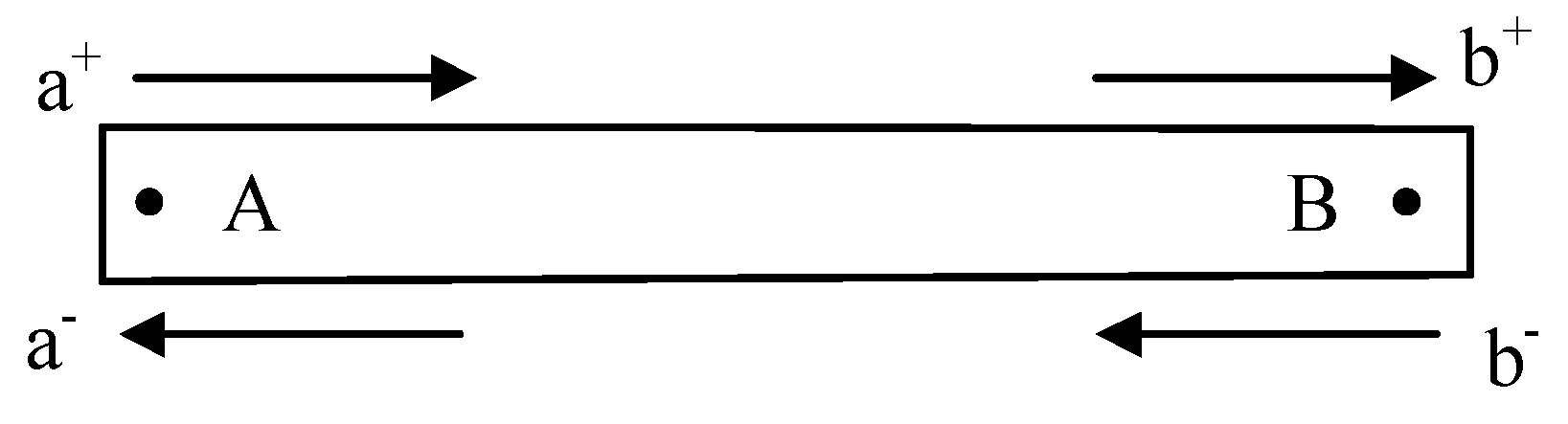
2.2. Propagation Matrix
2.3. Reflection at a Free Boundary
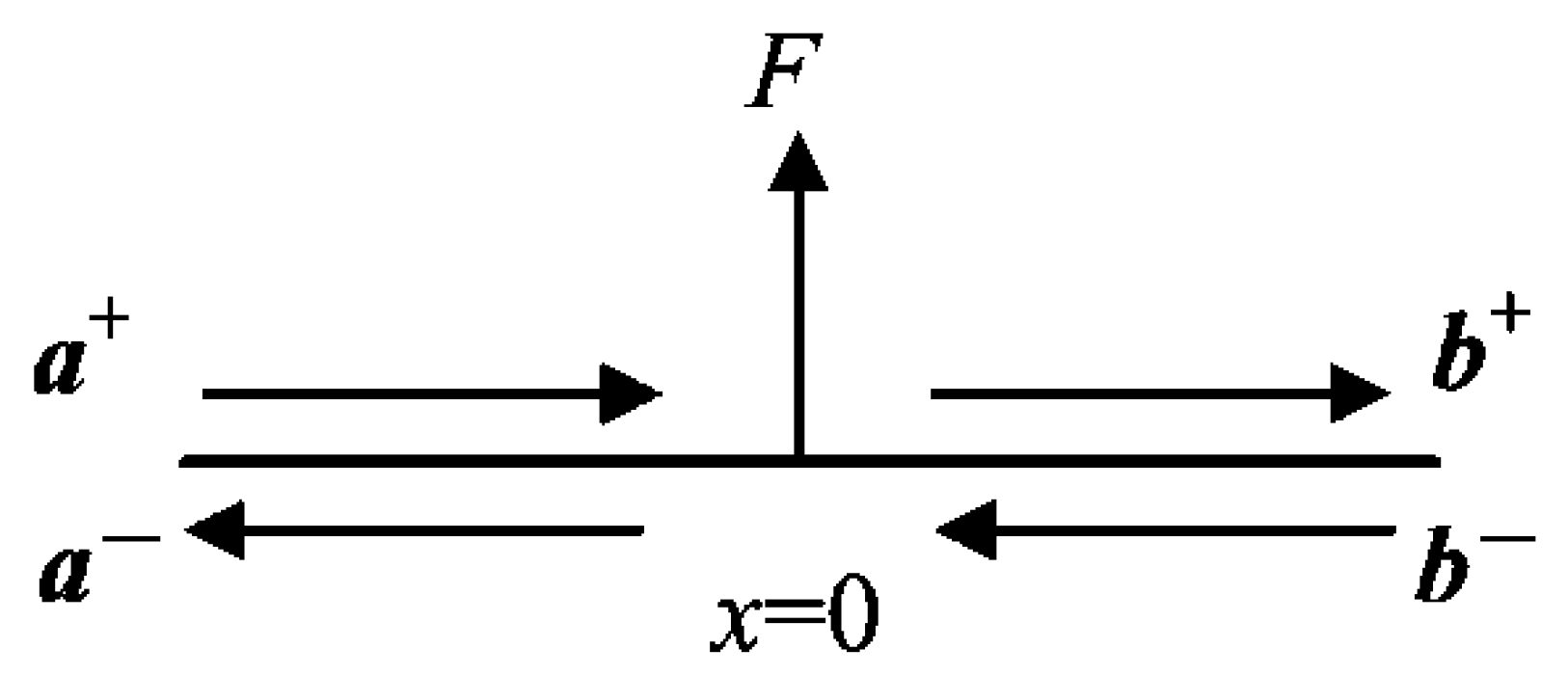
2.4. Applied Forces and Moments
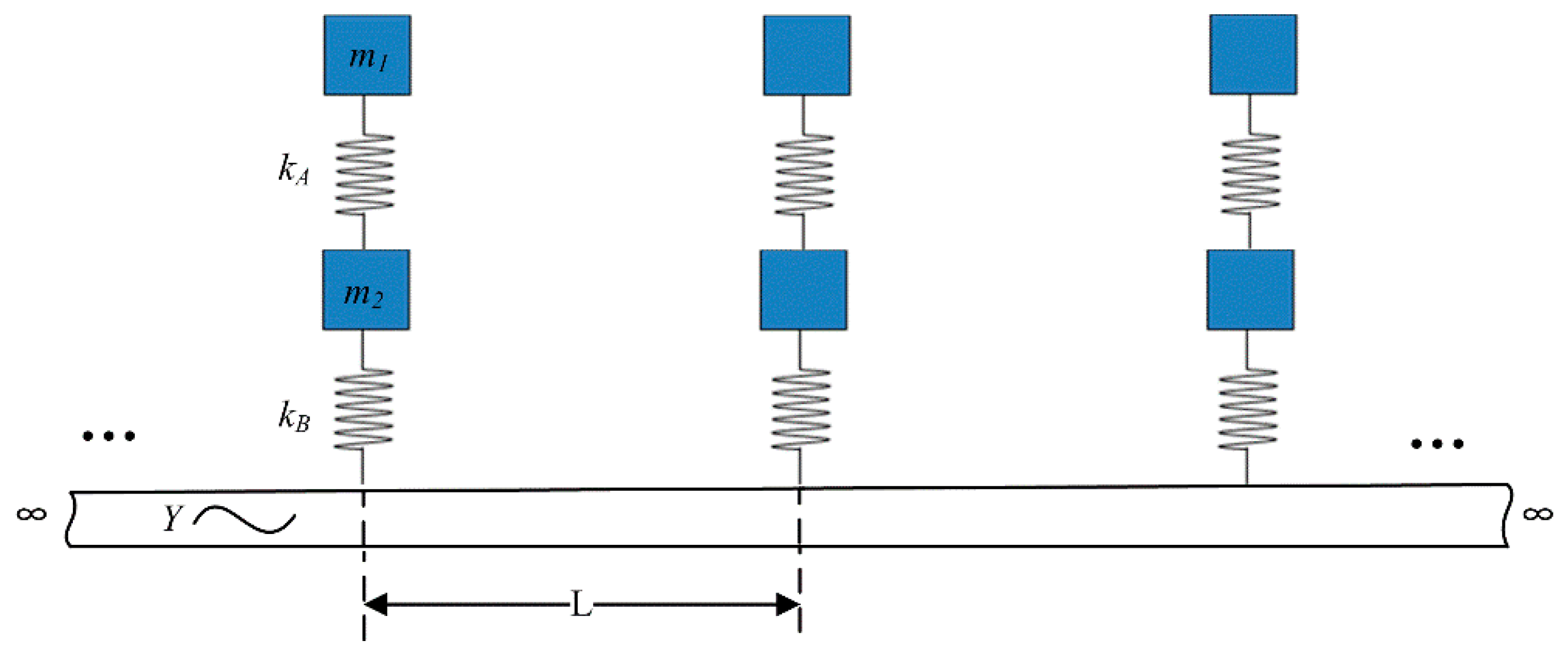
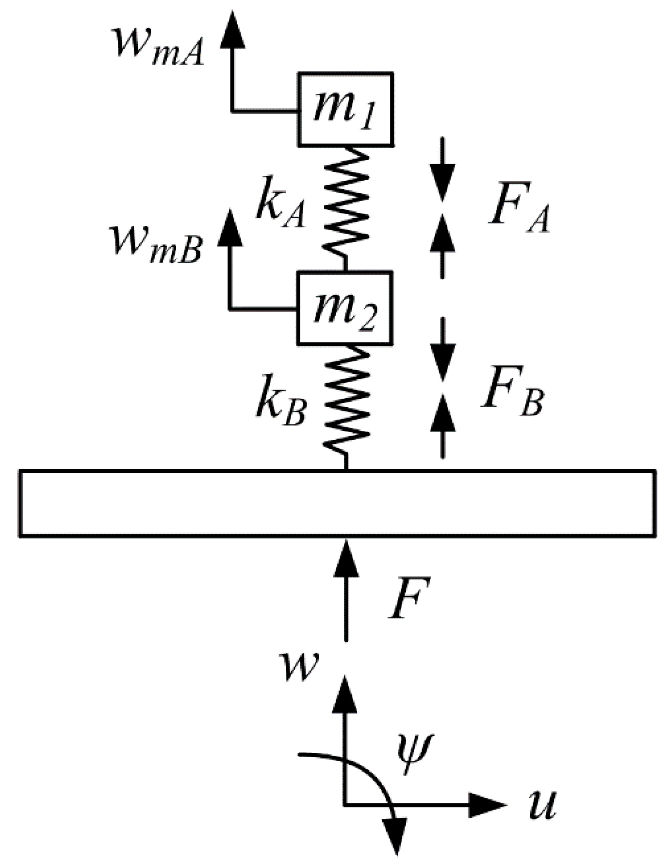
2.5. Transmission and Reflection at the 2-DOF Force-Type Resonator Attached Point
3. Vibration Analysis with Wave-Based Approach
4. Numerical Results and Discussion
5. Conclusions
Author Contributions
Funding
Data Availability Statement
Conflicts of Interest
References
- Lu, M.-H.; Feng, L.; Chen, Y.-F. Phononic crystals and acoustic metamaterials. Mater. Today 2009, 12, 34–42. [Google Scholar] [CrossRef]
- Hussein, M.I.; Leamy, M.J.; Ruzzene, M. Dynamics of Phononic Materials and Structures: Historical Origins, Recent Progress, and Future Outlook. Appl. Mech. Rev. 2014, 66, 040802. [Google Scholar] [CrossRef]
- Kaina, N.; LeMoult, F.; Fink, M.; Lerosey, G. Negative refractive index and acoustic superlens from multiple scattering in single negative metamaterials. Nat. Cell Biol. 2015, 525, 77–81. [Google Scholar] [CrossRef]
- Farajpour, M.R.; Shahidi, A.R.; Farajpour, A. Resonant frequency tuning of nanobeams by piezoelectric nanowires under thermo-electro-magnetic field: A theoretical study. Micro Nano Lett. 2018, 13, 1627–1632. [Google Scholar] [CrossRef]
- Rohani, R.E.; Farajpour, M.R. Influence of taxol and CNTs on the stability analysis of protein microtubules. J. Comput. Appl. Mech. 2019, 50, 140–147. [Google Scholar] [CrossRef]
- Timorian, S.; Petrone, G.; De Rosa, S.; Franco, F.; Ouisse, M.; Bouhaddi, N. Spectral analysis and structural response of periodic and quasi-periodic beams. Proc. Inst. Mech. Eng. Part C J. Mech. Eng. Sci. 2019, 233, 7498–7512. [Google Scholar] [CrossRef] [Green Version]
- Errico, F.; Petrone, G.; Rosa, S.D.; Franco, F.; Ichchou, M. On the concept of embedded resonators for passive vibration control of tyres. Proc. Inst. Mech. Eng. Part C J. Mech. Eng. Sci. 2021, 1–7. [Google Scholar] [CrossRef]
- Safarabadi, M.; Mohammadi, M.; Farajpour, A.; Goodarzi, M. Effect of surface energy on the vibration analysis of rotating nanobeam. J. Solid Mech. 2015, 7, 299–311. [Google Scholar]
- Lv, H.; Tian, X.; Wang, M.Y.; Li, D. Vibration energy harvesting using a phononic crystal with point defect states. Appl. Phys. Lett. 2013, 102, 034103. [Google Scholar] [CrossRef] [Green Version]
- An, X.; Lai, C.; Fan, H.; Zhang, C. 3D acoustic metamaterial-based mechanical metalattice structures for low-frequency and broadband vibration attenuation. Int. J. Solids Struct. 2020, 191, 293–306. [Google Scholar] [CrossRef]
- Yu, D.; Liu, Y.; Zhao, H.; Wang, G.; Qiu, J. Flexural vibration band gaps in Euler-Bernoulli beams with locally resonant structures with two degrees of freedom. Phys. Rev. B 2006, 73, 64301. [Google Scholar] [CrossRef]
- Yu, D.; Liu, Y.; Wang, G.; Zhao, H.; Qiu, J. Flexural vibration band gaps in Timoshenko beams with locally resonant structures. J. Appl. Phys. 2006, 100, 124901. [Google Scholar] [CrossRef]
- Ghayesh, M.H.; Farajpour, A. Vibrations of shear deformable FG viscoelastic microbeams. Microsyst. Technol. 2018, 25, 1387–1400. [Google Scholar] [CrossRef]
- Zhu, R.; Liu, X.; Hu, G.; Sun, C.; Huang, G. A chiral elastic metamaterial beam for broadband vibration suppression. J. Sound Vib. 2014, 333, 2759–2773. [Google Scholar] [CrossRef]
- Casalotti, A.; El-Borgi, S.; Lacarbonara, W. Metamaterial beam with embedded nonlinear vibration absorbers. Int. J. Non-Linear Mech. 2018, 98, 32–42. [Google Scholar] [CrossRef]
- Shuguang, Z.; Tianxin, N.; Xudong, W.; Jialu, F. Studies of band gaps in flexural vibrations of a locally resonant beam with novel multi-oscillator configuration. J. Vib. Control. 2015, 23, 1663–1674. [Google Scholar] [CrossRef]
- Gao, F.; Wu, Z.; Li, F.; Zhang, C. Numerical and experimental analysis of the vibration and band-gap properties of elastic beams with periodically variable cross sections. Waves Random Complex Media 2019, 29, 299–316. [Google Scholar] [CrossRef]
- Xiao, Y.; Wen, J.; Yu, D.; Wen, X. Flexural wave propagation in beams with periodically attached vibration absorbers: Band-gap behavior and band formation mechanisms. J. Sound Vib. 2013, 332, 867–893. [Google Scholar] [CrossRef]
- Filippi, M.; Pagani, A.; Carrera, E. High-order finite beam elements for propagation analyses of arbitrary-shaped one-dimensional waveguides. Mech. Adv. Mater. Struct. 2020, 1–9. [Google Scholar] [CrossRef]
- Chen, S.; Song, Y.; Zhang, H. Wave Propagation in L-Shape Beams with Piezoelectric Shunting Arrays. Shock. Vib. 2019, 2019, 1–14. [Google Scholar] [CrossRef] [Green Version]
- Liu, L.; Hussein, M.I. Wave Motion in Periodic Flexural Beams and Characterization of the Transition between Bragg Scattering and Local Resonance. J. Appl. Mech. 2011, 79, 011003. [Google Scholar] [CrossRef]
- Liang, X.; Wang, T.; Jiang, X.; Liu, Z.; Ruan, Y.; Deng, Y. A Numerical Method for Flexural Vibration Band Gaps in A Phononic Crystal Beam with Locally Resonant Oscillators. Crystals 2019, 9, 293. [Google Scholar] [CrossRef] [Green Version]
- Wang, T.; Sheng, M.-P.; Qin, Q.-H. Multi-flexural band gaps in an Euler–Bernoulli beam with lateral local resonators. Phys. Lett. A 2016, 380, 525–529. [Google Scholar] [CrossRef]
- Li, J.; Li, S. Generating ultra wide low-frequency gap for transverse wave isolation via inertial amplification effects. Phys. Lett. A 2018, 382, 241–247. [Google Scholar] [CrossRef]
- Wu, X.; Li, Y.; Zuo, S. The study of a locally resonant beam with aperiodic mass distribution. Appl. Acoust. 2020, 165, 107306. [Google Scholar] [CrossRef]
- Mei, C.; Mace, B.R. Wave Reflection and Transmission in Timoshenko Beams and Wave Analysis of Timoshenko Beam Structures. J. Vib. Acoust. 2005, 127, 382–394. [Google Scholar] [CrossRef]
- Lv, H.; Zhang, Y. A Wave-Based Vibration Analysis of a Finite Timoshenko Locally Resonant Beam Suspended with Periodic Uncoupled Force-Moment Type Resonators. Crystals 2020, 10, 1132. [Google Scholar] [CrossRef]
- Leamy, M.J. Exact wave-based Bloch analysis procedure for investigating wave propagation in two-dimensional periodic lattices. J. Sound Vib. 2012, 331, 1580–1596. [Google Scholar] [CrossRef]
- Lv, H.; Leamy, M.J. Damping Frame Vibrations Using Anechoic Stubs: Analysis Using an Exact Wave-Based Approach. J. Vib. Acoust. 2021, 143, 1–21. [Google Scholar] [CrossRef]
- Graff, K.F. Wave Motion in Elastic Solids; Ohio State University Press: Columbus, OH, USA, 1975. [Google Scholar]
- Mei, C. A Wave-Based Analytical Solution to Free Vibrations in a Combined Euler–Bernoulli Beam/Frame and a Two-Degree-of-Freedom Spring–Mass System. J. Vib. Acoust. 2018, 140, 061001. [Google Scholar] [CrossRef]


| Notation | Definition |
|---|---|
| Mass density | |
| Young’s modulus | |
| Shear modulus | |
| Cross-sectional area | |
| Area moment of inertia | |
| Shear coefficient | |
| Spring stiffness | |
| L | Lattice constant |
| Transverse deflection | |
| Longitudinal deflection | |
| Total bending | |
| Frequency | |
| Resonator mass |
| Acronym | Expansion |
|---|---|
| LR | Locally resonant |
| AMs | Acoustics metamaterials |
| EMs | Elastic metamaterials |
| TMM | Transfer matrix method |
| FEM | Finite element method |
| FRF | Frequency response function |
| LR | Locally resonant |
| Case | Relations | |||||
|---|---|---|---|---|---|---|
| Scheme 1 | Case 1 | 2~20 | 20~200 | 8.1921 | 8.1921 | |
| Case 2 | 20~200 | 2~20 | 8.1921 | 8.1921 | ||
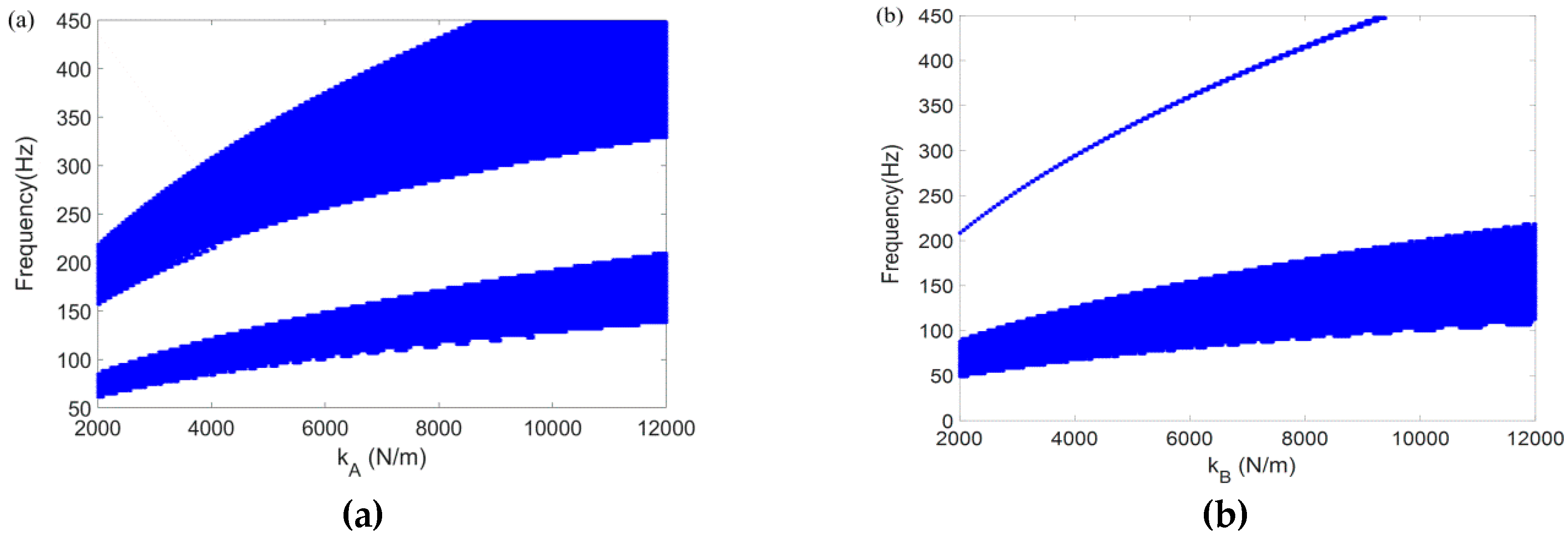
| Scheme 2 | Case 3 | 10 | 10 | 2000~12,000 | 8000~48,000 | |
| Case 4 | 10 | 10 | 8000~48,000 | 2000~12,000 | ||
| Resonator | Mode 1 (Hz) | Mode 2 (Hz) | ||||
|---|---|---|---|---|---|---|
| Resonator 1 | 10.027 | 10.027 | 88.97 | 232.8 | ||
| Resonator 2 | 20.054 | 10.027 | 74.48 | 277.9 | ||
| Resonator 3 | 10.027 | 20.054 | 101.7 | 203.5 | ||
| Resonator 4 | 20.054 | 20.054 | 88.91 | 232.77 |
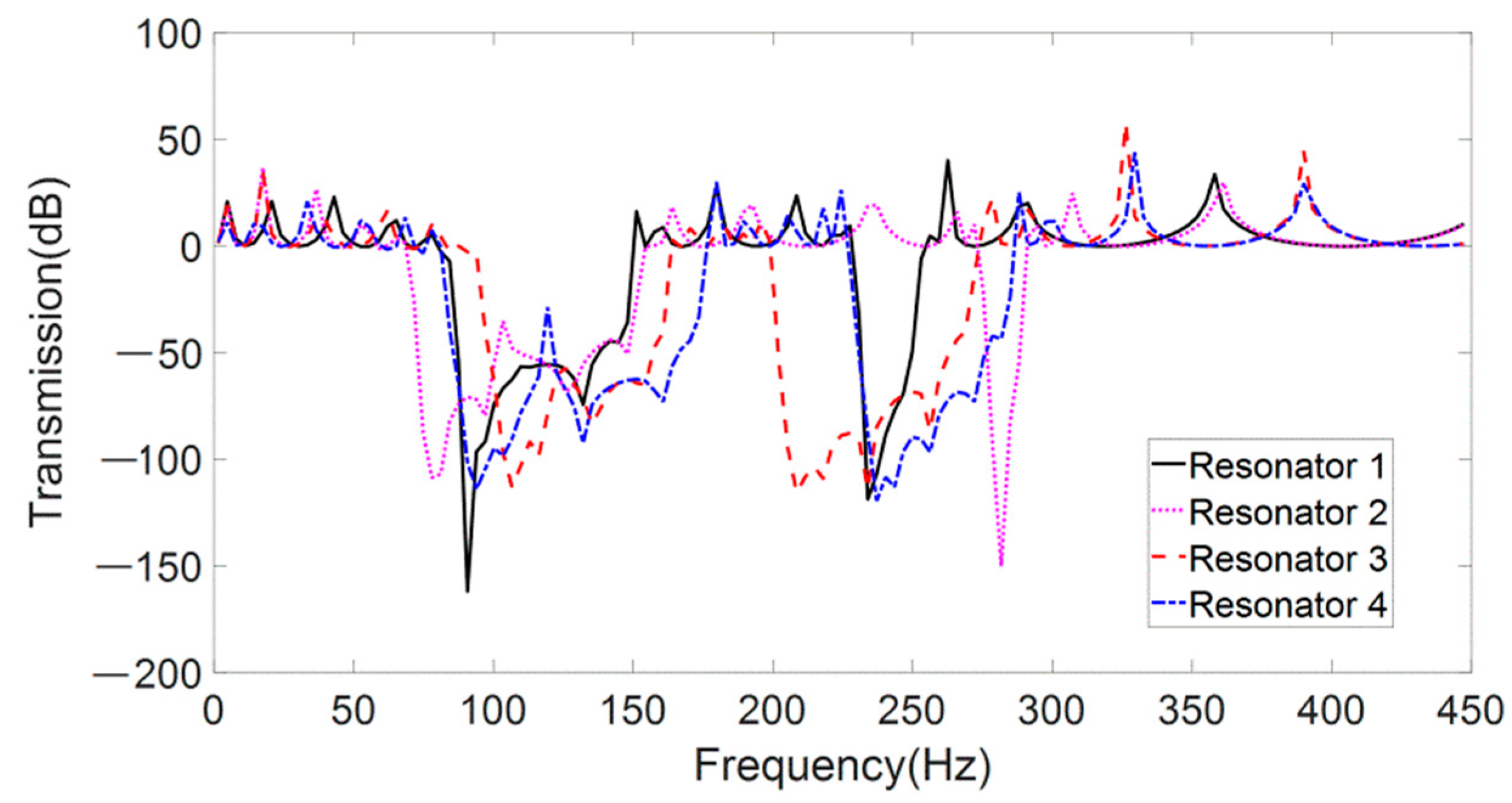
| Resonator | Lower Frequency Band-Gap (Hz) | Higher Frequency Band-Gap (Hz) | ||
|---|---|---|---|---|
| Region (Hz) | Width | Region (Hz) | Width | |
| Resonator 1 | [84.35, 148.01] | 63.66 | [230.77, 253.06] | 22.29 |
| Resonator 2 | [71.62, 151.20] | 79.58 | [275.34, 288.07] | 12.73 |
| Resonator 3 | [97.08, 160.75] | 63.67 | [202.13, 272.16] | 70.03 |
| Resonator 4 | [84.35, 173.48] | 89.13 | [227.59, 284.89] | 57.30 |
Publisher’s Note: MDPI stays neutral with regard to jurisdictional claims in published maps and institutional affiliations. |
© 2021 by the authors. Licensee MDPI, Basel, Switzerland. This article is an open access article distributed under the terms and conditions of the Creative Commons Attribution (CC BY) license (https://creativecommons.org/licenses/by/4.0/).
Share and Cite
Lv, H.; Li, S.; Huang, X.; Yu, Z. Band-Gap Properties of Finite Locally Resonant Beam Suspended Periodically with Two-Degree-of-Freedom Force Type Resonators. Crystals 2021, 11, 716. https://0-doi-org.brum.beds.ac.uk/10.3390/cryst11060716
Lv H, Li S, Huang X, Yu Z. Band-Gap Properties of Finite Locally Resonant Beam Suspended Periodically with Two-Degree-of-Freedom Force Type Resonators. Crystals. 2021; 11(6):716. https://0-doi-org.brum.beds.ac.uk/10.3390/cryst11060716
Chicago/Turabian StyleLv, Hangyuan, Shangjie Li, Xianzhen Huang, and Zhongliang Yu. 2021. "Band-Gap Properties of Finite Locally Resonant Beam Suspended Periodically with Two-Degree-of-Freedom Force Type Resonators" Crystals 11, no. 6: 716. https://0-doi-org.brum.beds.ac.uk/10.3390/cryst11060716