Article

Preparation of Aligned Steel-Fiber-Reinforced Concrete Using a Magnetic Field Created by the Assembly of Magnetic Pieces

1
School of Civil and Transportation Engineering, Hebei University of Technology, Tianjin 300401, China
2
Tianjin Port Engineering Institute, CCCC First Harbor Engineering Co. Ltd., Tianjin 300222, China
3
CCCC Infrastructure Maintenance Group Ltd., Beijing 100011, China
*
Authors to whom correspondence should be addressed.
Submission received: 31 May 2021 / Revised: 3 July 2021 / Accepted: 13 July 2021 / Published: 20 July 2021
(This article belongs to the Special Issue Advances in Green Building Materials and Structural Performances)

Abstract

:
In steel-fiber-reinforced composites, when the direction of a steel fiber is parallel to the direction of tensile stress, the capacity of the strengthening and toughening effect of the steel fiber can be fully applied to the composites. In this paper, a method to control the direction of steel fibers from one side surface of the mold full of a fresh mixture of steel-fiber-reinforced concrete using a magnet composed of small magnet squares is proposed, which has the advantage that the approach is suitable for specimens or elements with any size or shape. The influence of the method on the orientation effect of steel fiber is explored, and the flexural properties of the specimens prepared by different orientation methods are compared and analyzed through a three-point bending test. The test results show that the steel fibers in the mixture are successfully aligned by the magnetic treatment and the fiber orientation effective coefficient reaches 0.9 or more. The flexural properties of the aligned steel-fiber-reinforced cementitious composite (ASFRC) prepared by the magnetic device is significantly improved. The test results also show that the properties of the ASFRC prepared by the new method are comparable with that prepared by the previous electromagnetic field in terms of the fiber orientation effective coefficient and flexural strength.

1. Introduction

The addition of steel fibers can restrain the widening and propagation of cracks; therefore, steel-fiber-reinforced concrete is widely used in flooring, pavements, bridge decks, and other projects [1,2,3]. In practice, many structural members are often fixed in the direction of force during service. For example, the bottom of beam members is subjected to longitudinal tensile stress for a long time. Research on aligned steel-fiber-reinforced concrete shows that it enhances the tensile and bending properties along the direction of tensile stress. In the process of service, the stress of components generally has a constant direction. Only the steel fibers parallel to the direction of the tensile stress reinforce the matrix effectively. Therefore, steel fibers randomly distributed in the matrix may not completely contribute to the improvement of the flexural property, which leads to the waste of fibers. To avoid this, the approach of optimizing the orientation of steel fibers is necessary, and that is the purpose of this investigation.
Recently, a number of investigation have been carried out on the alignment of steel fiber in cementitious composites using electromagnetic fields generated by solenoids in their central closed space. Michels J. et al. [4] prepared aligned steel fiber mortar by placing the mixture into a hollow electromagnetic coil and vibrating table, in which the coil was wrapped with 100 turns of copper wire. Abrishambaf A. [5] used a setup that consisted of a copper wire coil wound around a U-shaped iron core to control the direction of steel fibers in ultra-high-performance concrete (UHPC). The setup can generate a uniform electromagnetic field between the U-shaped legs. Based on electromagnetic treatment, Mu et al. [6,7] successfully prepared aligned steel-fiber-reinforced cement-based composites by using a uniform magnetic field in the solenoid cavity, and the steel fiber orientation effective coefficient, which is the ratio of the tensile stress of the concerned specimen to that of the specimen with a completely uniaxial fiber distribution, reached 0.9 or higher. Wu [8] developed a setup to align steel fibers, which magnetically attracted the steel fibers, and then placed the steel fibers on the surface of concrete layer by-layer to form aligned steel-fiber-reinforced concrete. Ghailan D.B. [9] prepared aligned steel fiber self-compacting concrete with the fiber orientation coefficient between 0.8 and 0.95 through a solenoid. The methods mentioned above can effectively control the direction of steel fibers in concrete mixtures, but the size of concrete elements is strictly limited by the effective electromagnetic space, i.e., the space of the central hollow chamber of the solenoids. Therefore, it is difficult to apply this to a real construction member. Therefore, it is necessary to develop an approach that has no limit on the size of the specimens or structure members when the steel fibers inside are aligned so that it can be applied in practical construction. Obviously, the approach will promote the further application of aligned steel-fiber-reinforced concrete in practice, such as floors, the ground, and bridge panels.
In this paper, a method that can be used to align the steel fibers in concrete from one surface of real structures in construction was proposed. Firstly, the orientation device that can control the direction of steel fiber from one side of fresh concrete was developed. Secondly, the factors that influence the aligning of steel fibers were investigated, and the parameters were optimized. Finally, the influence of the dosage and type of steel fiber and the properties of the matrix on the alignment of steel fiber using a square magnet assembly was studied. Based on the results of this investigation, it will be possible to align the steel fibers in real structures in the future if the device developed can be combined with other construction equipment, such as a consolidating machine.

2. The Preparation of the Aligned Steel-Fiber-Reinforced Concrete

2.1. The Method of Aligning Steel Fibers by a Nonuniform Magnetic Field

For the construction of steel-fiber-reinforced concrete structures such as slabs, floors, pavement, and airports, if the steel fibers are aligned horizontally using a magnetic device, the device that generating the magnetic field can only be placed outside of the structures. At the same time, the magnetic line must be horizontal, and the magnetic induction should be strong enough to drive the steel fibers. Obviously, the magnetic field generated by the solenoids that are often used in the laboratory is not applicable because the effective working space of the solenoid is very limited, and the structures cannot be placed inside. The external magnetic field of a solenoid is similar to that of a bar magnet. The magnetic line diverges outward from the two poles to form a closed arc curve (Figure 1), and the magnetic induction intensity is very small. This article intended to assemble multiple magnets (bar magnets) to make their magnetic fields interfere with each other to form an approximately external plane magnetic field, which was used to align the steel fibers in the floor concrete.
The key to align the steel fibers using an external magnetic field of the assembly of bar magnets is to form a magnetic field with straight magnetic lines and constant magnetic induction intensity. However, the magnetic lines of a bar magnet are curves and sparse, as shown in Figure 1b, and the magnetic induction intensity is weak, which is not enough to drive the steel fiber to rotate. The magnetic lines at the poles of a bar magnet are dense, but the direction is radially towards or away the poles. Therefore, the magnetic field of a single bar magnet is incapable of aligning steel fibers in concrete. When two bar magnets come close to each other with different polarities, the magnetic lines between the two magnets, as shown in Figure 2, radially point from the N pole of one bar magnet to the S pole of another bar magnet. As the distance decreases, the magnetic lines at the gap between the two magnetic poles will be denser and the magnetic induction intensity will be higher.
As can be seen from Figure 3a, when three or more bar magnets are close to each other, the arc-shaped magnetic lines on the same side appear as wave crests and the distance between two adjacent peaks outside the blue dotted line is relatively far. The shorter the bar magnet and the closer the distance between adjacent bar magnets, the closer the distance between adjacent wave crests is. Wave crests outside the dotted line are similar to a wavy line, and while the distance of the wave crests is infinitely close to a point, the wavy magnetic line is approximately one straight line. Based on this principle, several magnets with small thicknesses are assembled with each other to form a bar magnet. Due to the magnetic leakage phenomenon between the small magnets, an external magnetic field with a wavy (approximately straight) magnetic line is formed. The part outside the dotted line tends to be a horizontal straight line, and the overall magnetic induction strength is enhanced (Figure 3b).
If two identical assembled bar magnets (having the same direction) are parallel and close to each other, the magnetic lines between the two combined bar magnets will become denser, as illustrated in Figure 4. At the same time, the wavy magnetic lines, which tend to be straight lines outside the blue dotted line, will become infinitely flat with the distance decreasing (Figure 5). The magnetic field created between the two bar magnets, especially the region between the blue dotted lines (Figure 5), may meet the requirements for aligning steel fibers in concrete. After a trial test, the magnetic field of the assembly of magnetic pieces worked, and steel fibers could be effectively aligned. Therefore, a special magnet was made for the preparation of aligned steel-reinforced concrete, which was by firstly assembling small magnet pieces to a bar magnet, then combining the bar magnets together and maintaining the same direction for all the magnet pieces.

2.2. Preparation of Aligned Steel-Fiber-Reinforced Concrete

Based on the above-mentioned principle, several bar magnets were assembled and used as the magnetic field orientation device. Comprehensively considering the requirements of surface magnetic induction intensity and the availability of magnets, rubidium iron boron magnet pieces were employed, as shown in Figure 6a. A number of rubidium iron boron magnets were assembled into bar magnets (Figure 6b), and several bar magnets were combined to be a square magnetic field orientation device (Figure 6c). The number of magnet pieces is dependent on the size of the concrete samples.
The aligned steel-fiber-reinforced concrete (ASFRC) was prepared by using the square magnetic field device developed above. In the preparation of the ASFRC, firstly, a plastic mold was filled with a fresh steel-fiber-reinforced concrete mixture and then placed on the compacting table. Before placing the device on the plastic mold, a partition board was placed on the plastic mold to prevent the steel fibers in the mixture from being taken up by the magnetic field. The detailed preparation setup of ASFRC can be seen in Figure 7. After the magnetic device and partition board were placed appropriately on the mold full of fresh concrete, the compacting table was switched on to vibrate for around 60 s. During the vibration, the mixture was in a flow state and the viscous resistance of the mixture was relatively small, so the fibers could be easily rotated under the driving of the magnetic force. After vibration, the compacting table was switched off, and then, the magnet device, as well as the partition board were taken off. The specimen was demolded after curing for 24 h, and ASFRC specimens were prepared.
During the preparation of the ASFRC by magnet treatment using the magnetic field device, both the viscosity of the matrix and the duration of magnetic treatment had an influence on the alignment and distribution of the steel fibers in the matrix [10,11].
The viscosity of the matrix influences the rotating speed of steel fiber under the driving of the magnetic force. A higher viscosity of the matrix may lead to the steel fiber having difficulty rotating and the failure of the alignment of the steel fibers. However, if the viscosity is too low, the steel fibers tend to sink. Therefore, it is critical to achieve an appropriate viscosity that prevents the steel fibers from sinking, yet that permits the rotation of the fibers under an external magnetic field. The viscosity of the matrix can be adjusted by changing the amount of superplasticizer.
The duration of magnetic field treatment also affects the alignment of steel fibers. When the time is too long, the mixture will bleed and segregate, which cause the decrease of the matrix strength. However, if the action time is too short, the steel fibers do not have enough time to rotate, which leads to the poor quality of fiber alignment. The experimental results showed that when the viscosity of the matrix was 0.8–1.2 Pa·s and the duration of the magnetic field treatment around 60 s, a reasonable orientation distribution of steel fibers was obtained.
The aligned steel-fiber-reinforced cementitious composite specimens with a size of 100 mm × 100 mm × 400 mm were prepared using the magnetic field device, in which the volume content of steel fiber was 0.8%, 1.2%, and 1.6%, respectively, and the water to cement ratio was 0.36 and 0.42, while that of cement to sand was 1:1.5. The specific mix proportion is shown in Table 1.
At the same time, the accompanying specimens having the same mix proportion, but had random steel fibers and aligned steel fibers using the conventional electromagnetic field in a solenoid were prepared [6]. The specimens were marked as ASFRC-I-W/C-Vf + S(H) and ASFRC-II-W/C-Vf + S(H) to represent the aligned steel-fiber-reinforced cementitious composite prepared by the magnetic field device and solenoid, respectively. SFRC-W/C-Vf + S(H) represents the random steel-fiber-reinforced cementitious composite. W/C and Vf are the water to cement ratio and steel fiber volume fraction, and S/H is the type of steel fiber (S for straight circular fiber and H for hooked end fiber). For example, ASFRC-I-0.36-0.8%S indicates that the specimen was prepared by the magnetic field of the assembly of magnet pieces, a water to cement ratio of 0.36, straight circular steel fiber, and a volume fraction of 0.8%. The raw materials used in the tests were ordinary Portland cement P·O 42.5, natural river sand with a fineness modulus of 2.5, and polycarboxylate superplasticizer. The physical parameters of the straight circular and hooked end steel fibers used in the tests are shown in Table 2.
The fractured cross-section and fiber distribution of the ASFRC and SFRC are shown in Figure 8. It can be seen that in the ASFRC, the steel fibers aligned very well.

3. Results of Aligning Steel Fibers in Cementitious Composites Using the Device of the Assembly of Magnetic Pieces

When the fresh SFRC mixture is treated using the magnetic device, the factors that affected the alignment of the steel fibers in the matrix include: (1) the magnetic induction intensity of the device; (2) the distance between the surface of the mixture and the device. Either increasing the magnetic induction intensity or reducing the distance can increase the magnetic force applied to the steel fibers, thus improving the quality of the alignment of the steel fibers. However, if the induction intensity is too strong, the steel fiber may be attracted by the device, thus leading to the uneven dispersion of the steel fibers. To understand this, in the preparation of the specimen ASFRC-I-0.36-1.2%S, the specimens were treated using the magnetic device with different surface magnetic induction intensities (B = 0 T, 0.1 T, 0.2 T, and 0.3 T, respectively) and the distribution of steel fibers at different positions was checked.
The specimens were horizontally split into three layers, as shown in Figure 9, and the distances from the splitting surfaces to the top surface of the specimen were 100 mm and 200 mm, which was also the distance between the magnetic device to the steel fibers at the splitting sections. The orientation of the fibers on the top and splitting surfaces was carefully checked. The orientation effective coefficient and dispersion of the steel fibers at different depths of the specimen were analyzed by checking the direction of the fiber, which is the angle (θ) between the direction of the steel fibers and the axis of the specimen, and counting the number of fibers (n) in the three sections. Then, the orientation effective coefficient of the steel fibers in the specimen can be computed using Equation (1) [12].
η θ = i = 1 n l × cos θ i n × l = 1 n i = 1 n cos θ i
where ηθ is the orientation effective coefficient, l is the length of the steel fiber, θi is the angle between the steel fiber and the axis of the specimen, and n is the number of steel fibers in each part of the section of the specimen.
The orientation effective coefficient (ηθ) and the number of steel fibers (n) in the upper layer, middle layer, and lower layer of the specimen section are shown in Table 3. It can be seen from Table 3 that the orientation effective coefficient of the samples treated with the magnetic device greatly increased compared with that without magnetic treatment (0 T). Keeping the distance between the device and the surface of the specimen constant, the orientation effective coefficient (ηθ) increased with the increase of the magnetic induction intensity. In the section at depth h = 200 mm, the orientation effective coefficient (ηθ) increased significantly with the increase in magnetic induction. In the middle layer with a depth of 100 mm, when the device used had a magnetic induction intensity of 0.3 T, 0.2 T, and 0.1 T, the orientation effective coefficient of the steel fibers was 0.91, 0.88, and 0.79, respectively. Therefore, the increase in the magnetic induction intensity of the device caused the improvement of the aligning quality of the steel fiber. Furthermore, based on this, the range of the effective aligning depth of steel fibers in structures or members can be determined according to the requirements and magnetic field induction intensity.
However, with the increase of the magnetic induction intensity of the device, the magnetic lines around the device become dense, and the steel fibers in the mixture may be attracted and move upwards or towards the magnet device, which affects the dispersion of the steel fiber. Figure 10 shows the ratio of the amount of steel fibers in different areas under the action of the device with various magnetic induction intensity. It can be seen from Figure 10 that the proportion of the steel fiber in the upper layer increased from 34% to 44% when the magnetic induction intensities increased from 0.1 T to 0.3 T, which is due to the attraction of magnetic field of the assembled magnets device. Therefore, the induction intensity of the magnetic field should be strong enough to align the steel fibers in the matrix, but should not be too strong to avoid the movement of the steel fibers caused by magnetic attraction.

4. Flexural Properties of the ASFRC Prepared Using the Magnetic Field Generated by the Assembly of Magnet Pieces

Through three-point bending tests, the properties of the ASFRC specimens prepared using the magnetic field generated by the assembly of magnet pieces were compared with that prepared using the electromagnetic field of the solenoid and the SFRC specimens with a random distribution of steel fibers inside. In the preparation of the ASFRC specimens, the magnetic induction intensity of the magnet assembly device was 0.1 T, and the distance from the surface of the mixture to the device was 0 mm. The specimens are denoted as ASFRC-I. The ASFRC specimens prepared by solenoid are denoted as ASFRC-II, and the SFRC with random steel fibers is denoted as the SFRC.

4.1. Three-Point Bending Test

According to ASTM C1609 [13], 3-point bending tests were performed using specimens with a size of 100 mm × 100 mm × 400 mm. The test approach is shown in Figure 11. In the tests, the displacement control method was adopted, and the initial loading speed was 0.1 mm/min. When the midspan deflection reached 3 mm, the loading speed was increased to 0.5 mm/min. The experimental tests were stopped when the midspan deflection reached 7 mm. The load and the midspan deflection of the test were recorded through the load sensor and the LVDT, respectively, and thereby, the load midspan deflection curves were obtained.

4.2. Flexural Property

The flexural strengths of ASFRC-I, ASFRC-II, and the SFRC in each mix proportion are shown in Table 4. It can be seen from Table 5 that compared with the SFRC, the flexural strength of ASFRC-I was significantly improved in each mix proportion. When the fiber volume content was 0.8%, 1.2%, and 1.6%, the flexural strength of ASFRC-I was 19.8%, 67.3% and 60.3% higher than that of the SFRC, respectively. Furthermore, the flexural strength of ASFRC-I was comparable to that of ASFRC-II, which indicated that the aligning of steel fibers in ASFRC-I using the assembly of magnets was successful.

4.3. Flexural Toughness

The load–deflection curves obtained from the three-point bending test are depicted in Figure 12. It can be seen from Figure 12 that the ascending branches of ASFRC-I and the SFRC in each group basically coincide. However, the peak and the descending branch of the curve of ASFRC-I is much higher than that of the SFRC, which indicates that the flexural toughness of ASFRC-I was improved compared with the SFRC. On the other hand, the load–deflection curve of ASFRC-I is close to that of ASFRC-II. This implies that the magnetic device developed has the same ability as the electromagnetic solenoid to align steel fibers in cementitious composites.
The flexural toughness of the specimen was evaluated by the toughness index T150 and the residual flexural strength [14]. According to ASTM C1609, T150 is the area of the load–deflection curve when the midspan deflection approaches 1/150 of the span length of the specimen. The toughness index T150 of the specimens is shown in Table 5. The equation of the residual flexural strength is as follows:
f 150   =   P 150 l b d 2 ,   f 600   =   P 600 l b d 2
where: f 150 and f 600 —the residual flexural strength at a midspan deflection of l / 150 and l / 150 , respectively; b—section width of the specimen; d—section height of the specimen.
The average residual flexural strength results of each group of specimens are shown in Table 5. As shown in Table 5, the flexural toughness of the specimen prepared by the device of assembled magnets (ASFRC-I) was significantly higher than that of the SFRC. When the fiber volume fraction was 0.8%, 1.2%, and 1.6%, the flexural toughness of ASFRC-I was 92.9%, 54.8%, and 95.2% higher than that of SFRC, respectively. The residual flexural strength of ASFRC-I was 1.5–3-times higher than that of SFRC when the midspan deflection was l/150 and l/600. Therefore, the specimen prepared using the device of assembled magnetic pieces is much superior to the SFRC in flexural toughness and residual flexural strength. Furthermore, the flexural toughness and the remaining flexural strength of the ASFRC-I are comparable to those of ASFRC-II.

5. Conclusions

In this paper, a magnetic device for aligning steel fibers in cementitious composite structures or members was developed, which consisted of a number of small magnet pieces assembled according to the design, employed to treat the fresh SFRC mixtures from the top surface in a mold to align the steel fibers inside. The results of the aligning of steel fibers and the parameters that affected the alignment of the steel fibers were investigated. The flexural properties of the ASFRC specimens prepared using the new device were compared with those of conventionally cast specimens through three-point bending tests. The following conclusions can be drawn from this investigation.
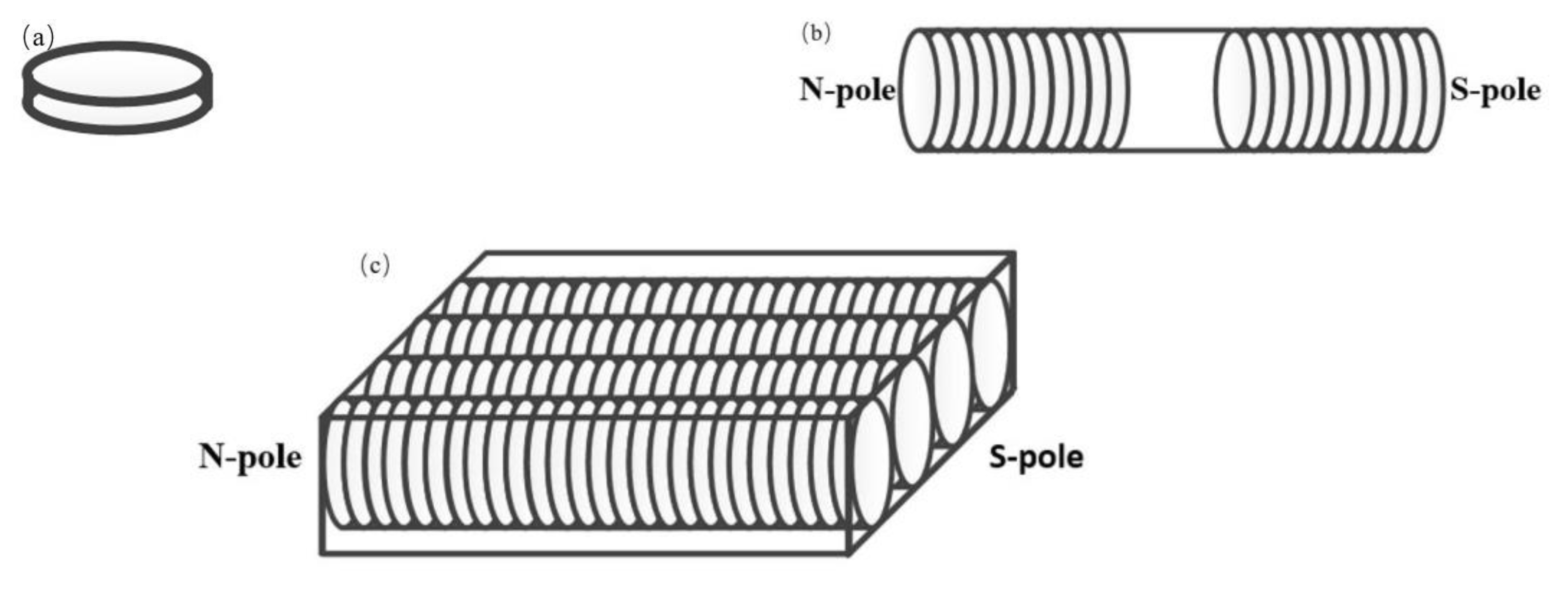
  • When a number of small magnets are assembled and form a plate, the magnetic field near the surface of the plate has almost straight magnetic lines. The magnetic field can be used to align the steel fibers in cementitious composites, which was proven by experimental tests. After trials tests, a magnetic device was developed, which was the assembly of small magnetic pieces arranged in the same manner. The advantage of using the new device to prepare the ASFRC was that in the aligning process, the magnetic field device only treated the structures or members on one surface, and there was no limit on the size or shape of the structures or members.
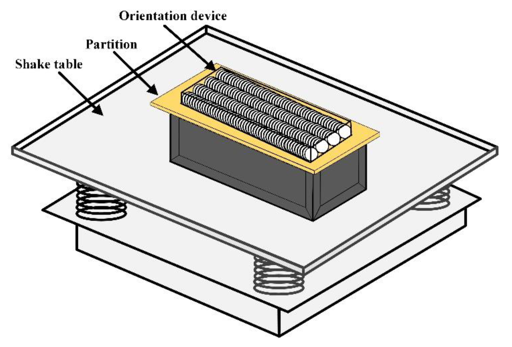
  • In the preparation of the ASFRC specimens, the fresh mixture of cementitious composites in the mold were treated using the device on one surface when compacted. Both the magnetic induction intensity of the device and the distance between the device and surface of the specimen significantly influenced the quality of the aligning of the steel fibers in the matrix. The appropriate parameters (magnetic field induction intensity and distance of magnetic treatment of the specimen using the device) were optimized experimentally. By using the developed device, aligned steel-fiber-reinforced cementitious composite (ASFRC) specimens were prepared, and the orientation effective coefficient of the steel fibers in the ASFRC specimens reached 0.9 or higher.
  • Compared with a random steel-fiber-reinforced cementitious composite (SFRC), the flexural properties of the ASFRC prepared by the device were significantly improved, in which the flexural strength and flexural toughness of ASFEC were increased by 20–70% and 40–150%, respectively. On the other hand, the flexural properties of the specimen prepared by the device were comparable to that of the specimen prepared by the solenoid, which indicated that the device has excellent performance in aligning steel fibers.

Author Contributions

Conceptualization, R.M.; methodology, R.D. and H.L.; investigation, H.C.; data curation, Q.C. and C.F. All authors read and agreed to the published version of the manuscript.

Funding

This work was supported by the National Natural Science Foundation of China (No. 51878239, 52078180) and the Natural Science Foundation of Hebei Province of China (No. E20202151).

Conflicts of Interest

The authors declare no conflict of interest.

References

  1. Ferrier, E.; Michel, L.; Zuber, B.; Chanvillard, G. Mechanical behaviour of ultra-high-performance short-fibre-reinforced concrete beams with internal fibre reinforced polymer bars. Compos. B Eng. 2015, 68, 246–258. [Google Scholar] [CrossRef]
  2. De Andrade, R.G.M.; Pfeil, M.S.; Battista, R.C.; Filho, R.; Lopes, R.T. Comparison between methods to determine the fibre orientation factor of an HPFRC bridge box girder. Constr. Build. Mater. 2020, 269, 121291. [Google Scholar] [CrossRef]
  3. Shen, P.L.; Lu, J.X.; Zheng, H.B.; Lu, L.N.; Wang, F.Z.; He, Y.J.; Hu, S.G. Expansive ultra-high performance concrete for concrete-filled steel tube applications. Cem. Concr. Compos. 2020, 114, 12. [Google Scholar] [CrossRef]
  4. Michels, J.; Gams, M. Preliminarno istraživanje utjecaja orijentacije vlakana u mikroarmiranim mortovima. Građevinar 2016, 68, 645–655. [Google Scholar]
  5. Abrishambaf, A.; Pimentel, M.; Nunes, S. Influence of fibre orientation on the tensile behaviour of ultra-high performance fibre reinforced cementitious composites. Cem. Concr. Res. 2017, 97, 28–40. [Google Scholar] [CrossRef]
  6. Mu, R.; Li, H.; Qing, L.; Lin, J.; Zhao, Q. Aligning steel fibers in cement mortar using electro-magnetic field. Constr. Build. Mater. 2017, 131, 309–316. [Google Scholar] [CrossRef]
  7. Mu, R.; Wei, L.; Wang, X.; Li, H.; Qing, L.; Zhou, J.; Zhao, Q. Preparation of aligned steel fiber reinforced cementitious composite and its flexural behavior. J. Vis. Exp. 2018, 136, 56307. [Google Scholar] [CrossRef] [PubMed]
  8. Wu, K.; Li, H.; Chai, Z.G.; Shi, N.; Lin, S.Q. A Steel Fiber Directional Arrangement Device and Steel Fiber Concrete Manufacturing Method. CN Patent 110216776A, 10 September 2019. [Google Scholar]
  9. Ghailan, D.B.; Al-Ghalib, A.A. Magnetic alignment of steel fibres in self-compacting concrete. Aust. J. Struct. Eng. 2019, 21, 333–341. [Google Scholar] [CrossRef]
  10. Meng, W.; Khayat, K.H. Improving flexural performance of ultra-high-performance concrete by rheology control of suspending mortar. Compos. B Eng. 2017, 117, 26–34. [Google Scholar] [CrossRef]
  11. Mu, R.; Xing, P.; Yu, J.; Wei, L.; Zhao, Q.; Qing, L.; Zhou, J.; Tian, W.; Gao, S.; Zhao, X.; et al. Investigation on reinforcement of aligned steel fiber on flexural behavior of cement-based composites using acoustic emission signal analysis. Constr. Build. Mater. 2019, 201, 42–50. [Google Scholar] [CrossRef]
  12. Mu, R.; Zhao, Q.; Tian, W. Investigation on the preparation and properties of aligned steel fibre reinforce cement paste. J. Hebei Univ. Technol. 2012, 41, 101–104. [Google Scholar]
  13. Test, C.C.; Drilled, T.; Concrete, C.; Panels, S.T. Standard Test Method for Flexural Performance of Fiber Reinforced Concrete (Using Beam with Third-Point Loading); ASTM International: West Conshohocken, PA, USA, 2005. [Google Scholar]
  14. Sadrmomtazi, A.; Gashti, S.H.; Tahmouresi, B. Residual strength and microstructure of fiber reinforced self-compacting concrete exposed to high temperatures. Constr. Build. Mater. 2020, 230. [Google Scholar] [CrossRef]
Figure 1. Distribution of magnetic lines. (a) Solenoid; (b) bar magnets.
Crystals 11 00837 g001
Figure 2. The distribution of magnetic lines when the different magnetic poles of two bar magnets approach each other.
Crystals 11 00837 g002
Figure 3. The distribution of the magnetic lines of combined bar magnets. (a) Three bar magnets; (b) multiple bar magnets.
Crystals 11 00837 g003
Figure 4. Distribution of magnetic lines at the poles. (a) Single combined bar magnet; (b) two combined bar magnets are parallel to the same pole.
Crystals 11 00837 g004
Figure 5. The magnetic field line of a parallel pole combination bar magnet.
Crystals 11 00837 g005
Figure 6. Experimental device for controlling steel fiber with a non-uniform magnetic field. (a) Rubidium iron boron magnet; (b) bar magnet; (c) assembled magnetic field device.
Crystals 11 00837 g006
Figure 7. Preparation device for the aligned steel-fiber-reinforced concrete (ASFRC).
Crystals 11 00837 g007
Figure 8. The specimen of the steel-fiber-reinforced cementitious composites. (a) The fractured surface of the ASFRC; (b) the fractured surface of the SFRC.
Crystals 11 00837 g008
Figure 9. The schematic diagram of the division of the specimen.
Crystals 11 00837 g009
Figure 10. The quantity proportion of the steel fiber in different areas with a distance of 0 mm.
Crystals 11 00837 g010
Figure 11. Schematic diagram of the three-point bending test.
Crystals 11 00837 g011
Figure 12. Load–span deflection curve. (a) W/C =0.36, Vf = 0.8%, straight circular fiber; (b) W/C = 0.36, Vf = 1.2%, straight circular fiber; (c) W/C = 0.36, Vf = 1.6%, straight circular fiber; (d) W/C = 0.36, Vf = 1.2%, hooked end fiber; (e) W/C = 0.42, Vf = 1.2%, straight circular fiber.
Crystals 11 00837 g012
Table 1. Mix proportion of steel-fiber-reinforced cementitious composites.
Type of SpecimenWater
Cement
Ratio
Water (kg/m3)Cement (kg/m3)Sand (kg/m3)Water Reducer (kg/m3)Steel Fiber (kg/m3)
ASFRC-I-0.36-0.8%S0.3626974711201.462.4
ASFRC-I-0.36-1.2%S0.3626573611041.593.6
ASFRC-I-0.36-1.2%H0.3626573611041.593.6
ASFRC-I-0.36-1.6%S0.3626172510881.6124.8
ASFRC-I-0.42-1.2%S0.4230773110970.693.6
Table 2. Characteristic parameters of the steel fiber.
Type of
Steel Fiber
Density (kg/m3)Average Length (mm)Equivalent Diameter (mm)The Ratio of Length to
Diameter
Elastic Modulus (GPa)Tensile Strength (MPa)
Straight circular type /Hooked type7800300.5602101150
Table 3. The orientation effective coefficient (ηθ) and the number of steel fibers (n) in each part of the cross-sections of the specimens.
Type of Specimen0 mm
ηθ
100 mm
ηθ
200 mm
ηθ
nηθnηθnηθ
0 TUpper layer510.54520.53470.50
Middle layer520.54550.55510.51
Lower layer480.52470.52500.52
0.1 TUpper layer500.95480.92370.88
Middle layer490.92490.91290.79
Lower layer490.91420.86610.68
0.2 TUpper layer610.93520.94510.91
Middle layer550.92500.92450.88
Lower layer370.95470.90420.86
0.3 TUpper layer720.94620.94540.93
Middle layer590.93550.92510.91
Lower layer340.92380.90440.90
Table 4. Flexural strength of ASFRC-I, ASFRC-II, and the SFRC.
GroupFlexural Strength
(MPa)
GroupFlexural Strength
(MPa)
ASFRC-I-0.36-0.8%S5.98ASFRC-I-0.36-1.2%H11.46
ASFRC-II-0.36-0.8%S5.96ASFRC-II-0.36-1.2%H11.65
SFRC0.36-0.8%S5.22SFRC0.36-1.2%H7.71
ASFRC-I-0.36-1.2%S8.35ASFRC-I-0.42-1.2%S7.12
ASFRC-II-0.36-1.2%S7.86ASFRC-II-0.42-1.2%S7.09
SFRC0.36-1.2%S4.99SFRC0.42-1.2%S4.23
ASFRC-I-0.36-1.6%S10.98
ASFRC-II-0.36-1.6%S10.69
SFRC0.36-1.6%S6.85
Table 5. Toughness index of steel-fiber-reinforced cement-based unidirectional slab specimens.
GroupP600 (kN)ƒ600 (MPa)P150 (kN)ƒ150 (MPa)T150 (J)Growth Rate
ASFRC-I-0.36-0.8%S12.4795.6169.1814.13122.38292.9%
ASFRC-II-0.36-0.8%S11.7655.2949.6674.35022.03089.9%
SRFRC0.36-0.8%S10.2764.6244.7452.13511.600
ASFRC-I-0.36-1.2%S17.7417.98313.4576.05631.51554.8%
ASFRC-II-0.36-1.2%S17.2037.74114.8286.67331.49854.7%
SRFRC0.36-1.2%S10.9994.9509.2744.17320.364
ASFRC-I-0.36-1.6%S21.9469.87615.2936.88238.99495.2%
ASFRC-II-0.36-1.6%S22.1289.95816.8107.56538.30391.7%
SRFRC0.36-1.6%S11.8355.3266.3852.87319.976
ASFRC-I-0.36-1.2%H25.45911.45715.2646.86939.32841.2%
ASFRC-II-0.36-1.2%H24.21910.89818.1748.17842.75453.5%
SRFRC0.36-1.2SH16.6217.47911.7525.28827.844
ASFRC-I-0.42-1.2%S4.5416.54311.9375.37227.354148.2%
ASFRC-II-0.42-1.2%S13.5266.08710.8214.86925.151128.3%
SRFRC0.42-1.2%S5.4212.4395.3282.39811.019
Publisher’s Note: MDPI stays neutral with regard to jurisdictional claims in published maps and institutional affiliations.

