
Acoustic Focusing with Intensity Modulation Based on Sub-Wavelength Waveguide Array

Department of Physics, College of Science, Yanbian University, Yanji 133002, China
*
Author to whom correspondence should be addressed.
Crystals 2021, 11(12), 1461; https://0-doi-org.brum.beds.ac.uk/10.3390/cryst11121461
Submission received: 23 October 2021
/
Revised: 19 November 2021
/
Accepted: 23 November 2021
/
Published: 26 November 2021
(This article belongs to the Special Issue Functional Materials and Metamaterials)
Abstract
:Acoustic focusing with intensity modulation plays an important role in biomedical and life sciences. In this work, we propose a new approach for simultaneous phase and amplitude manipulation in sub-wavelength coupled resonant units, which has not been reported so far. Based on the equivalent impedance and refractive index modulation induced by the change of geometry, arbitrary amplitude response from 0 to 1 and phase shift from 0 to 2π is realized. Thus, the acoustic focusing with intensity modulation can be achieved via waveguide array. Herein, the focal length can be adjusted by alternating the length of supercell, and the whole system can work in a broadband of 0.872f0–1.075f0. By introducing the coding method, the thermal viscosity loss is reduced, and the wavefront modulation can be more accurate. Compared with previous works, our approach has the advantages of simple design and broadband response, which may have promising applications in acoustic communication, non-destructive testing, and acoustic holography.
1. Introduction
Studies regarding metamaterial have become a hot topic in the last several years [1,2,3,4]. Among them, acoustic focusing is of great interest given its numerous promising applications such as biomedical imaging and non-destructive testing, among others. Traditionally, acoustic focusing can be achieved using phased array transducers, which has complex circuits and high costs. In recent years, the development of an acoustic artificial period structure, also known as acoustic metamaterial, has provided new means for the realization of acoustic focusing [5].
It has been demonstrated that acoustic gradient index (GRIN) lens [6,7,8] can be realized by gradually changing the size of phononic crystals. However, the size of GRIN lens is relatively large at low frequency due to the “wavelength-size” limitation in phononic crystals. To break this limitation, some researchers have proposed a new concept of metasurface (MS) in sub-wavelength scale, which can achieve wavefront manipulation using ultrathin structures. Although various previous works have realized acoustic focusing by taking advantage of MS with phase modulation (PM) [9,10,11,12,13,14,15,16,17,18], there are relatively few studies on the manipulation of focusing intensity. Essentially, the realization of acoustic focusing with intensity modulation in sub-wavelength scale needs to design an acoustic MS that can achieve both amplitude modulation (AM) and PM simultaneously. In 2017, Tian et al. [19] proposed a MS with decoupled AM and PM, which can manipulate the intensity of the transmitted waves. Nevertheless, it is based on the decomposition of the meta-cell into two units, one responsible for tuning the phase and the other serving as an amplitude modulator, which may increase the complexity of the structure. In 2018, Ghaffarivardavagh et al. [20] present a space-coiling metamaterial, enabling acoustic control with simultaneous AM and PM. However, they adopted four degrees of freedom including the width of the incident port, the thickness of coil’s wall, the number of coils, and the common radio of channel width to manipulate the wavefront, which may bring a limitation to the application. Therefore, it is important to explore a new kind of MS to achieve acoustic focusing with intensity modulation by utilizing the simple unit cell on a sub-wavelength scale.
In this work, we demonstrate the possibility of simultaneous AM and PM in sub-wavelength coupled resonant units, so as to achieve acoustic focusing with intensity modulation based on waveguide array. The units proposed in our work are composed of five resonators with different cross-sectional lengths. According to the effective medium method, we verify that the AM is due to the presence of the acoustic reactance term, and the PM owes to the shift of equivalent velocity. In addition, the whole acoustic system can work in a broadband of 0.872f0–1.075 f0. By introducing the coding method, the thermal viscosity loss could be reduced and the intensity modulation of focusing could be more accurate.
2. Design and Result
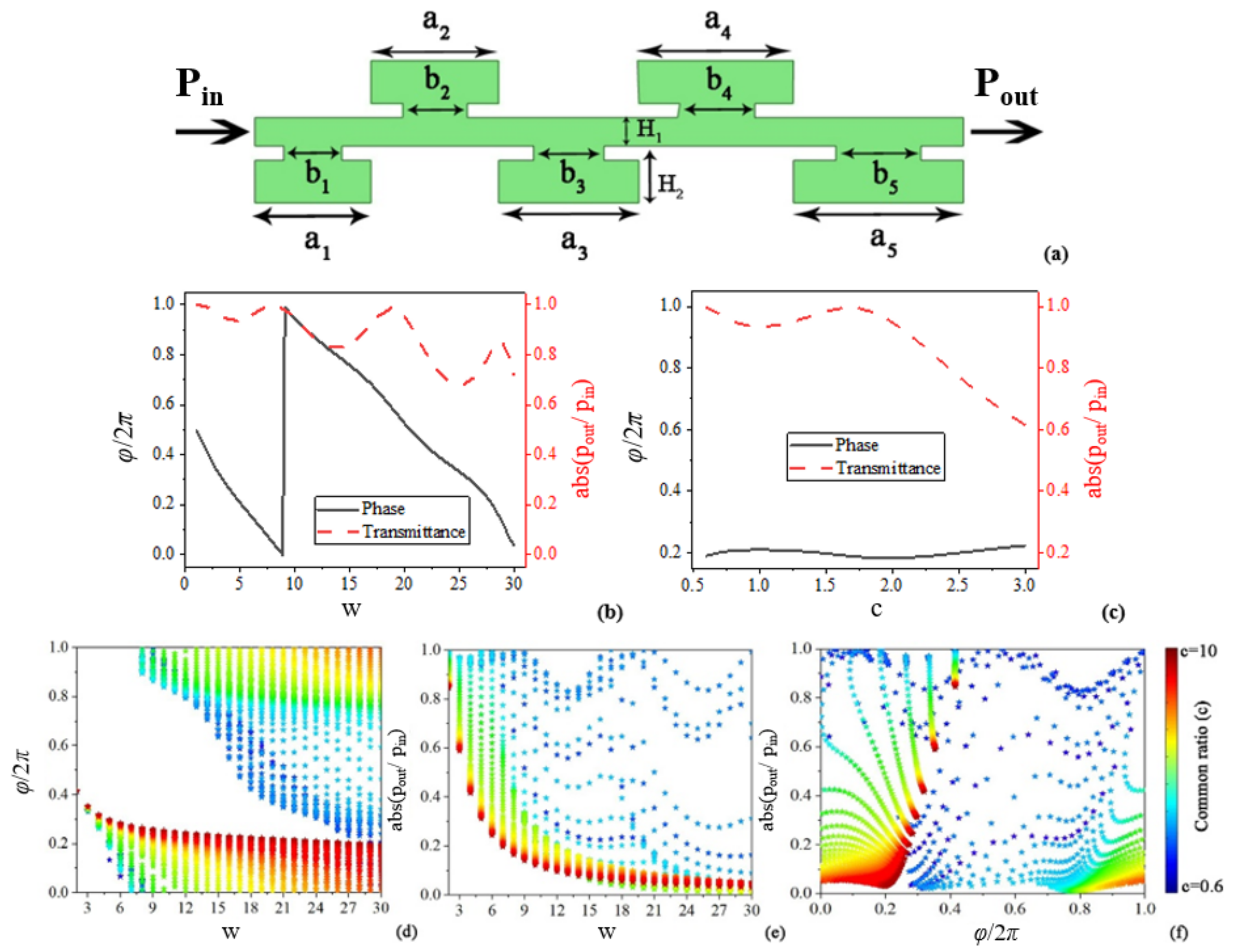
As shown in Figure 1a, the waveguide unit (L * H = 0.5λ * 0.1λ) proposed in this work is composed of five resonators, whose cross-sectional length varies with the gradient and can be regarded as a geometric sequence. L and H are the length and height of the waveguide unit. Following the reference [20], the structure featuring a gradient in channel spacing possesses complex acoustic impedance, which is a key to realizing simultaneous phase and amplitude modulation. Thus, we also design a gradient waveguide. If we define ‘c’ as the common ratio, the cross-sectional length and neck length of five resonators can be expressed as: a1 = (1 − c)*L/(1 − c5), a2 = ca1, a3 = c2a1, a4 = c3a1, a5 = c4a1; b1 = a1/2, b2 = cb1, b3 = c2b1, b4 = c3b1, b5 = c4b1. It should be noted that different values of H1 and H2 lead to various effective acoustic velocities, so as to achieve different phase delays. Thus, the phase modulation can be realized by altering the values of H1 and H2. Thus, the heights of channel and resonators are adjustable and can be expressed as H1 = H/w and H2 = (H − H/w)/2, respectively. Where ‘w’ is a scale factor to control the height of H1 and H2. The waveguide unit is filled with air and the incident wavelength is 0.1 m. Of note, the wavefront modulation can be realized by changing the geometric parameters of the waveguide unit. Therefore, the number, length, or position of the resonators can be regarded as the degrees of freedom to manipulate the transmission waves. To simplify the design method, we only adopt common ratio ‘c’ and scale factor ‘w’ to manipulate the transmitted waves in this work. Herein, we fix the number of resonant unit (n = 5) and define the neck length as bn = an/2.
To calculate the amplitude and phase response of the waveguide unit, finite element software “COMSOL Multiphysics” is adopted. The frequency domain in the pressure acoustic module is utilized, and the background of the medium is selected as air: ρair = 1.21 kg/m3, cair = 343 m/s. The amplitude and phase responses can be obtained by “” and “”, respectively, with being the acoustic pressure of the transmission wave. As shown in Figure 1b,c, although full PM can be achieved by manipulating the scale factor ‘w’, full PM and full AM are unable to be realized simultaneously by utilizing only one degree of freedom (‘c’ or ‘w’). Therefore, we have to add an extra degree of freedom and investigate the possibility of using both common ratio ‘c’ and scale factor ‘w’ to achieve complete wavefront modulation. As shown in Figure 1d,c, when the scale factor ‘w’ is not large enough (w < 18), the full PM and AM cannot be achieved even though two degrees of freedom are adopted here. With the increase of ‘w’, the range of phase and amplitude shift is expanded, that is to say, the ability of PM and AM could be improved with the decrease of channel width. In addition, the common ratio ‘c’ also has a great influence on wavefront modulation. For PM, it is hard to achieve 0–0.4π and 1.6π–2π without high-value of common ratio ‘c’; For AM, we have to increase the value of ‘c’ to obtain a lower transmittance (for example, the value of ‘c’ needs to exceed 5 if we want to obtain a transmittance around 0.1) with the altering of ‘w’. Therefore, full PM and AM could be realized independently when the value of ‘w’ and ‘c’ is large enough. In addition, as shown in Figure 1f, almost any combination of phase and amplitude can be realized accordingly by appropriately selecting geometric parameters. Each phase distribution in the range of 0–2π corresponds to an amplitude coverage of 0–1, which can be utilized to achieve both PM and AM simultaneously, so as to realize acoustic focusing with intensity modulation.
When the resonators shown in Figure 1a have the same cross-sectional length, that is c = 1 and a1 = a2 = a3 = a4 = a5, the waveguide array becomes a traditional MS similar to the previous research. Considering a general metasurface with a thickness of Lm, equivalent acoustic impedance of Zm and wave number of Km placed in infinite space with acoustic impedance of Z, the following equation can be deduced [20]:
where θ represents the transmitted phase. The complete wavefront modulation cannot be achieved under this condition owing to the existence of coupling between the transmission phase and amplitude shown in Equation (1). To avoid this situation, the presence of the acoustic reactance term is necessary [20].
The waveguide unit with several resonators proposed in our work, instead of having a constant resonator length, features a change in length at each step is governed by a constant common ratio, defined as: . In which and are the resonator length of and resonator, respectively. By this definition, the waveguide can be well approximated as an exponential horn with a flare constant of for structures with . In which N is the number of resonator and is the effective length of the waveguide. The acoustic transmission coefficient can be solved as
with ain and aout are the resonator length for the first and last resonators, respectively, L is the length of the unit, k is wave number, and and are defined as and . Thus, it can be obtained that the transmission amplitude will be bounded by . Therefore, waveguide unit featuring a gradient in resonator length has the ability to modulate the transmission amplitude.
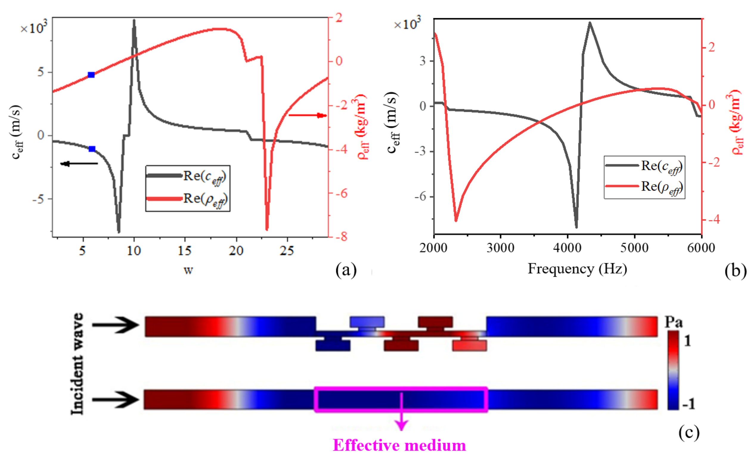
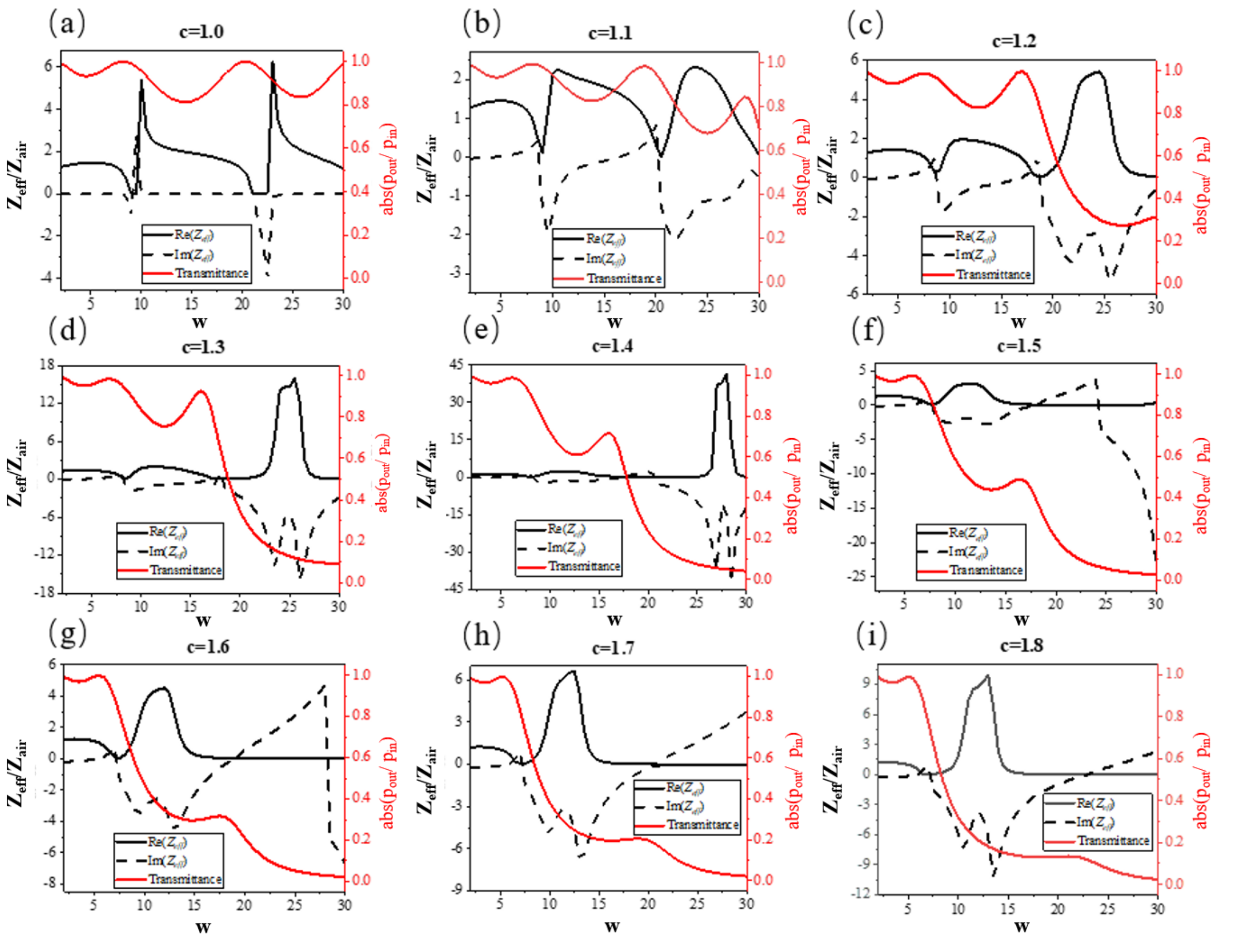
Herein, the effective acoustic parameters could be obtained by calculating the reflection and transmission coefficients of the waveguide unit [21] (see Appendix A). As shown in Figure 2a, the effective acoustic velocity and mass density are different under various channel widths. Meanwhile, as illustrated in Figure 2b, the effective acoustic velocity and density depends on frequency as well. To verify the reliability of effective medium (EM), a data point with w = 6 is selected and the corresponding acoustic parameters are substituted into the EM at 3430 Hz. As shown in Figure 2c, the distribution of acoustic field in EM is almost the same as that in waveguide unit, which indicates that the proposed EM method has a good applicability. Note that the difference in the sound pressure between the resonator part and its effective medium can be neglected because our aim is to retrieve the equivalent properties of the waveguide unit, which only needs to ensure the agreement between the waveguide unit and its effective medium in transmission field and reflection field. In other words, the effective medium only needs to provide the same amplitude and phase of reflection and transmission waves, which can be verified in Figure 2c. Therefore, we could obtain the effective acoustic impedance with different values of ‘c’, as shown in Figure 3. For c = 1.0, or equally the traditional unit cell, the acoustic reactance term exists only at resonance coupling of the incident wavelength and the structure, which cannot reduce the amplitude sharply in a wide range. Compared with ‘c = 1′, the lower bound of transmittance expands gradually with the rising of ‘c’, and the full amplitude coverage (0–1) can be realized around c = 1.5. That is to say, as the value of ‘c’ increases, the amplitude of transmitted waves could be manipulated effectively because the complex acoustic impedance can be realized by the gradient change in cross-section of the resonators. Moreover, with the rising of ‘c’, the broad amplitude coverage could be achieved with a smaller value of ‘w’. For instance, in the case of c = 1.2 (Figure 3c), the transmission coefficient can be reduced to 0.3 only when w = 30. However, in the cases of c = 1.2–1.8 (Figure 3d–i), the transmission coefficient of 0.3 could be achieved in lower value of ‘w’. It is not hard to imagine when the value of ‘c’ is large enough, such as c = 10 (shown in Figure 1e), the wide range of AM may be realized by making use of different values of ‘w’ independently, which provides more degrees of freedom for complete wavefront modulation.
As mentioned in the work [22], the key to realize PM is to obtain the continuously gradient phase (CGP), which is equivalent to making the refractive index of the EM satisfy the following requirement:
where ni represents the refractive index of the ith EM; λ0 represents the incident wavelength; p represents the length of supercell composed of EM; m represents the number of rigid walls in a supercell. We could also consider each EM is filled with materials having different wave velocities:
where ci represents the velocity in the ith EM. According to Equation (3), the effective refractive index can be obtained by inversion of the effective velocity. Thus, it can be concluded that the phase shift is due to the change of effective velocity in waveguide unit. Different values of ‘w’ and ‘c’ lead to various acoustic velocities, so as to achieve a wide range of phase shift in individual parameter combination of ‘c’ and ‘w’.
Please note that the device proposed in reference [20] is a space-coiling metamaterial, through which the phase and amplitude modulations are able to be achieved simultaneously as well. However, they adopted four degrees of freedom including the width of incident port, the thickness of coil’s wall, the number of coils, and the common radio of channel width to manipulate the wavefront. As a comparison, only two degrees of freedom, common ratio ‘c’ and scale factor ‘w’, are needed in our work to obtain the simultaneous modulation of phase and amplitude for transmitted wavefront. Consequently, the approach we proposed is simpler than that in reference [20] because the parameter optimization is more convenient in this work, which greatly simplifies the design philosophy and is more suitable for practical applications. Moreover, the focusing intensity shown in Ref. [20] is fixed, and they did not mention the concept of intensity modulation of the focus, while it can be realized in our work, further promoting the application of the design.
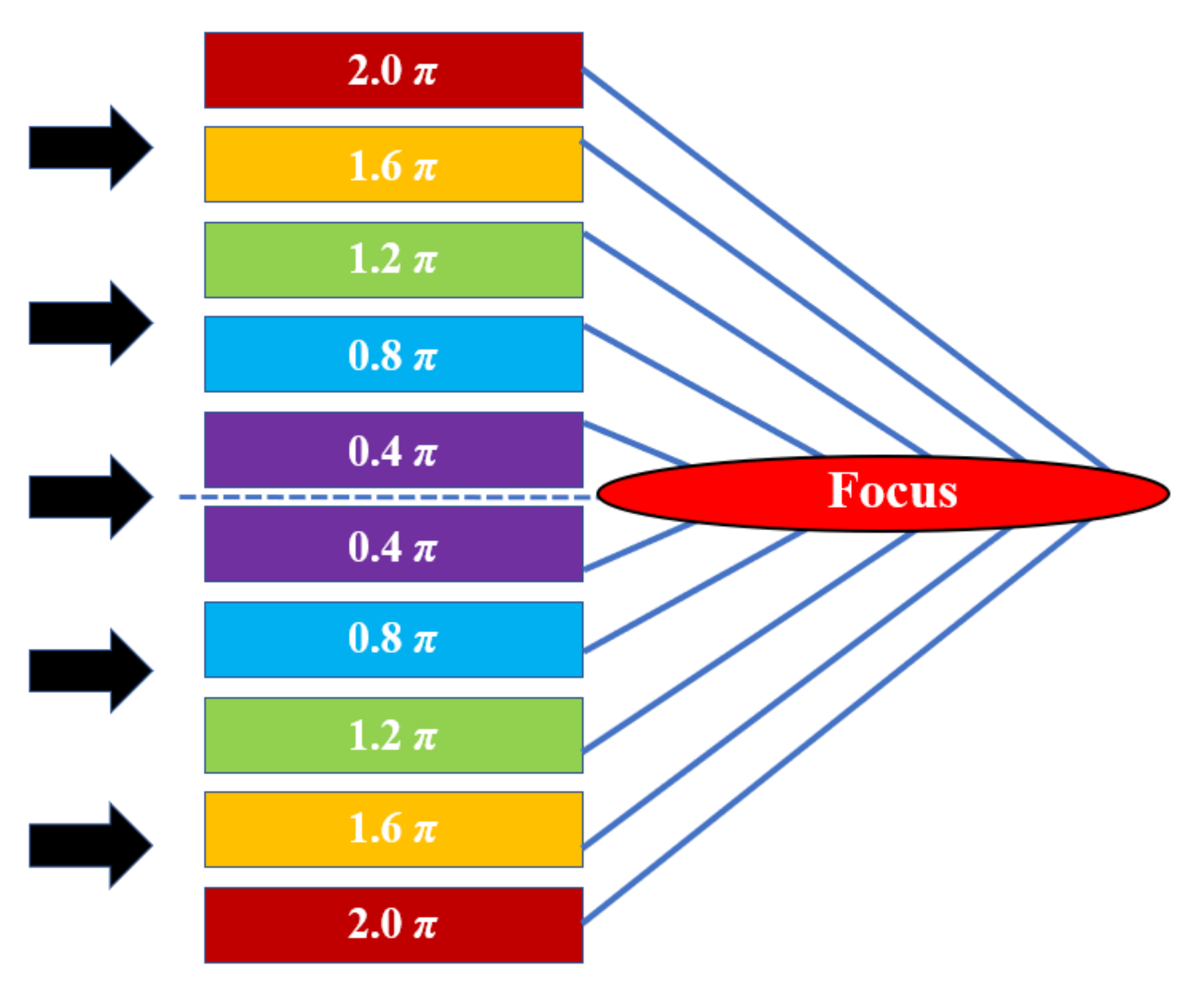
Herein, as shown in Figure 4, five waveguide units with CGP in the range of 0.4π–2.0π in steps of 0.4π is designed. Analogous to the generalized Snell’s law in optics, if an acoustic wave with the frequency of f is incident from one medium to another, the generalized Snell’s law in acoustics can be expressed as follows:
where θi and θt represent the angle of incidence and refraction, respectively; ki = 2πf/ci, kt = 2πf/ct, ci and ct represent the acoustic velocity of the incident medium and the transmitted medium. When the plane wave is normally incident on the waveguide array (θi = 0), Equation (4) can be rewritten as:
As mentioned before, the EM of each unit have different wave velocities. Thus, the wave fronts inside different waveguide units accumulate different phase changes (ϕi) when they pass though the waveguide array. The phase difference between the ‘acoustic paths’ in neighboring waveguide units is a constant and is given by Δϕ = 2π/5 = 0.4π. Thus, the phase change between the neighboring supercells composed of waveguide units is always 2π, which is required to maintain a continuous and smooth wavefront pattern of the transmitted wave. We assume that the length of supercell is p, then we can use a constant transverse phase gradient (dϕ/dx = 2π/p) to describe the phase changes on the surface of the waveguide array composed of supercells. Such a transverse phase gradient gives rise to oblique transmitted waves due to the generalized Snell’s law of refraction in Equation (5), and the refraction angle can be manipulated by changing the parameter p:
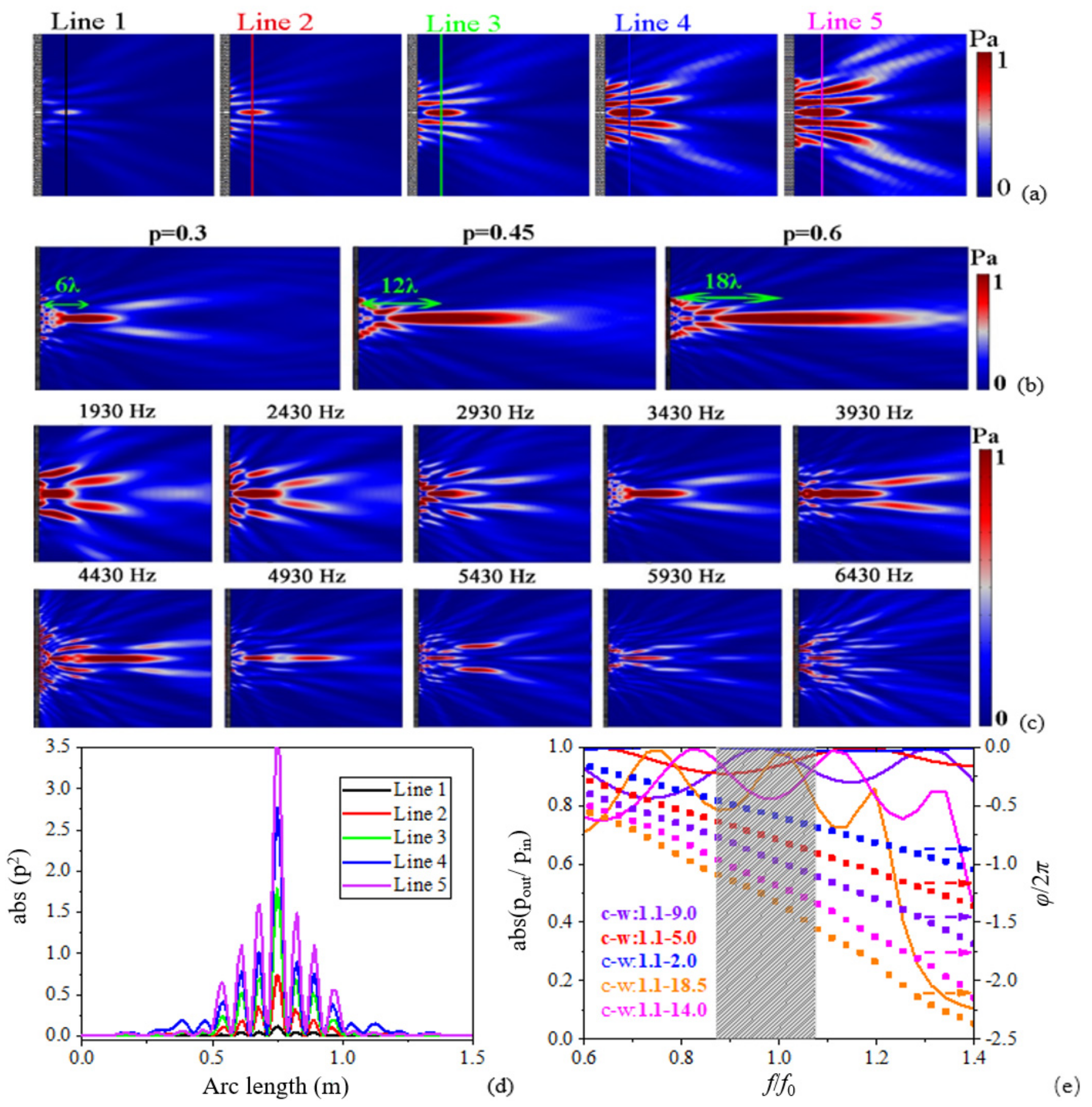
Thus, we could construct a PM structure by arraying waveguide units with CGP, and the acoustic focusing phenomenon can be achieved through constructive interference. Furthermore, according to Table 1, any single phase in a CGP corresponds to five continuously gradient amplitudes (CGA), which can manipulate the transmissivity of acoustic waves. Herein, finite element software (COMSOL Multiphysics) is used to calculate the acoustic intensity field of the structure. The frequency domain in pressure acoustic module is adopted, and the background of the medium is selected as air: ρair = 1.21 kg/m3, cair = 343 m/s. The outside boundaries are set as plane wave radiation conditions, so as to avoid the unwanted reflections. As shown in Figure 5a,d, acoustic focusing phenomena with different intensities are obtained by altering the parameters of ‘c’ and ‘w’, which satisfies our purpose of manipulating the acoustic focusing intensity by utilizing only two degrees of freedom of the structure. In addition, as shown in Figure 5b, the focal length could be modulated by alternating the length of supercell, which provides a way to achieve long-distance acoustic beam collimation.
Another advantage of the waveguide unit shown in our work is its broadband in wavefront modulation. As shown in Figure 5c, acoustic focusing can be achieved within the band range of 1930 Hz–6430 Hz due to the coupling resonances given by five resonators in a waveguide unit. Of note, the focusing quality decreases in high frequency, which partly attributes to the non-strict linear response between the phase shift and the incident wavelength as shown in Figure 5e. On the other hand, the transmissivity of some waveguide units is reduced rapidly at high frequency, which also affects the quality of focus. Nevertheless, as shown in grey area in Figure 5e, it has a reasonably good performance when 0.872 ≤ f/f0 ≤ 1.075 because the transmission coefficient is over 0.8 and the spanning range of phase shift expands to 80% of 2π within this band, which reveals that the acoustic system can work in a broadband.
When sound wave propagates in narrow buildings and geometric structures, thermal loss and viscous loss will lead to sound wave attenuation. Specifically, the loss occurs in the acoustic thermal boundary layer and viscous boundary layer near the wall. In order to establish a model that matches the actual situation, we need to consider this phenomenon and evaluate the impact of these losses on the thermoviscous acoustic system. To eliminate the thermal viscosity loss (TVL), we propose the coding method to construct the lens. Only two kinds of waveguide units with opposite phase responses are required, and the huge TVL caused by some harsh parameters of the units with narrow width can be avoided in this case. The key to realizing the acoustic focusing is to make the acoustic waves reaching the focus have the same phase, that is, constructive interference occurs (see Appendix B). Based on this theory, we can modulate the wavefront by arranging the position of two coding units with phase difference of π. To make acoustic waves converge at a certain point, the placement positions of two coding units shall meet the following requirements:
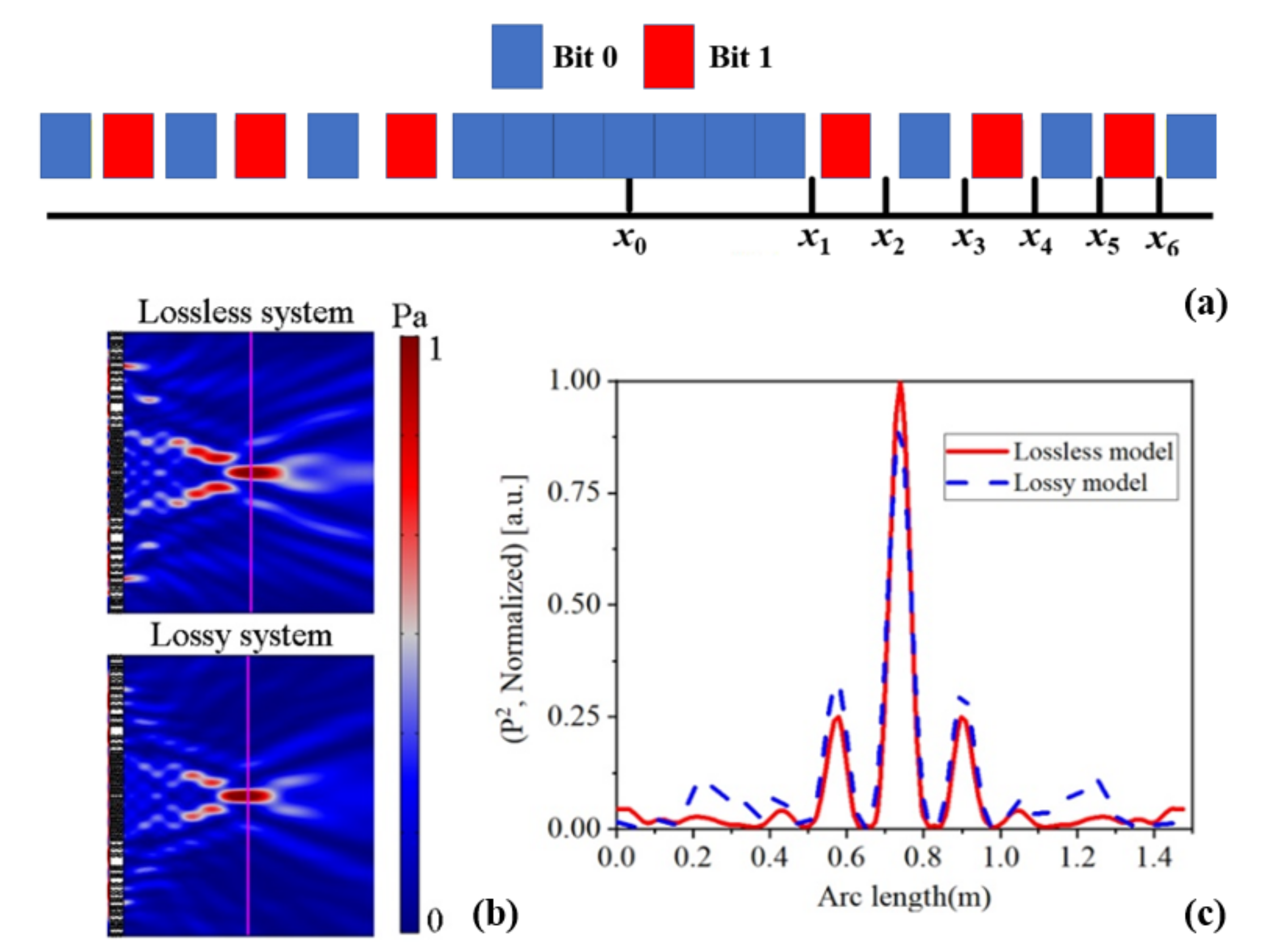
where xi+1 and xi represent the position of two coding units; q represents the focal length. Under this condition, as shown in Figure 6a, we only need two waveguide units with a phase difference of π, which provides an opportunity to improve the minimum size of the structure to reduce the TVL and facilitate sample preparation. Thus, we could select two coding units with low value of ‘w’ to achieve acoustic focusing. According to Equation (7), we set q = 0.6 m, λ = 0.1 m, x0 = 0 m here. Then, the position of other coding units can be determined in the following order: x1 = 0.25000 m, x2 = 0.36056 m, x3 = 0.45000 m, x4 = 0.52915 m, x5 = 0.60208 m, x6 = 0.67082 m. To numerically calculate the lossless structure and lossy structure, we adopt the ‘Pressure acoustic module’ and ‘thermoviscous acoustic module’, respectively, in finite element software of COMOSL. As shown in Figure 6b, acoustic focusing is realized based on coding method using only two waveguide units with ‘w = 2′ and ‘w = 9.5′, respectively. By comparing the intensity of acoustic pressure in both lossy and lossless system shown in Figure 6c, it can be confirmed that the TVL is small and can be ignored here.
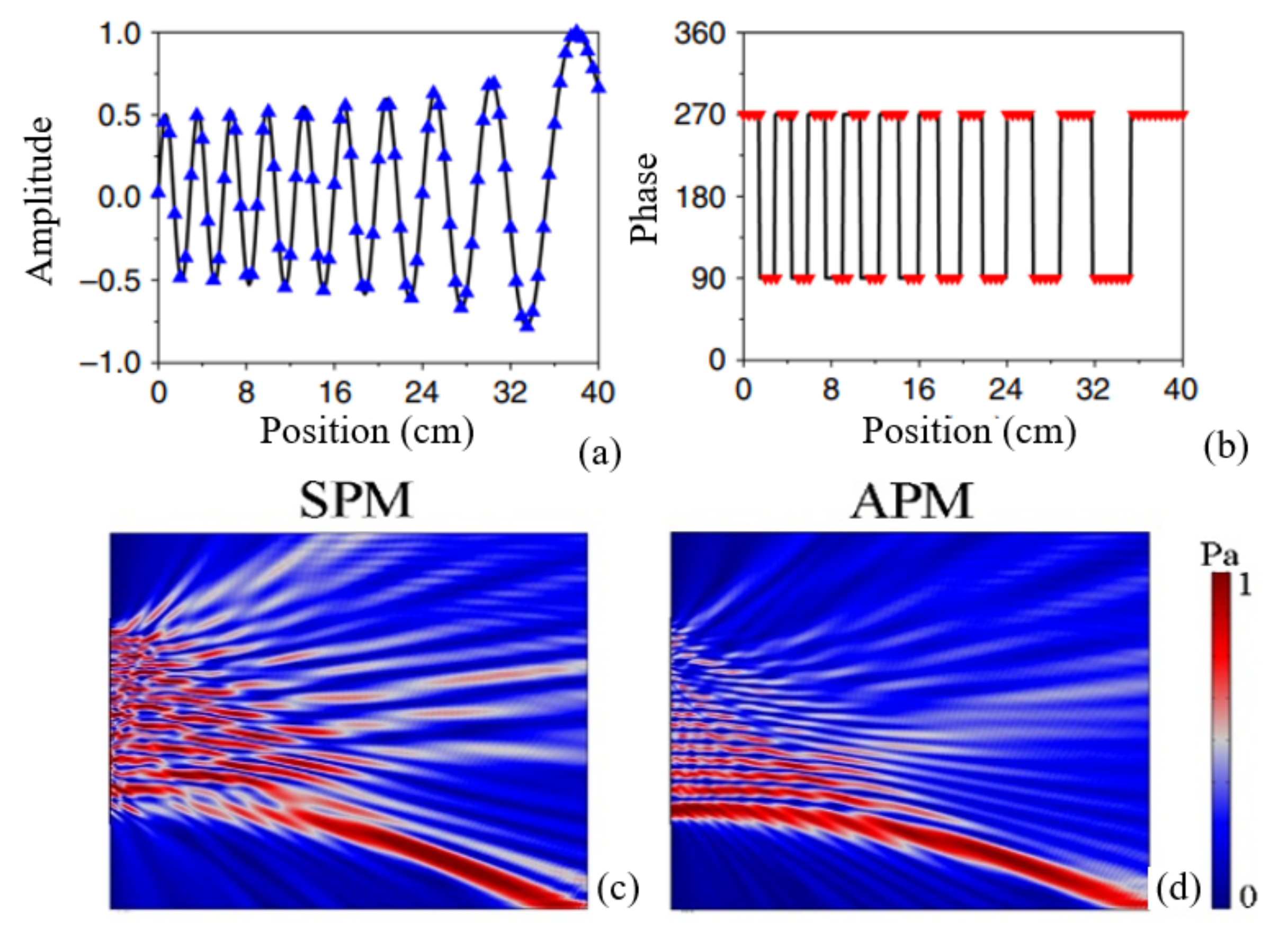
As another interesting application of the structure proposed in this work, the capability of wavefront shaping may be improved by means of the MS composed of waveguide units with simultaneous amplitude and phase modulation (APM) compared with traditional single-phase modulation (SPM). As an illustrative example, in the case of Airy beam shown in Figure 7, both APM and SPM have been considered. Figure 7a,b are the discrete amplitude and phase information for waveguide array. For Airy beam based on SPM, some unwanted waves along other directions are generated in the transmission field due to the parasitic diffraction [23]. While for Airy beam based on APM, perfect Airy beam is produced. The pressure fields shown in Figure 7c,d indicate that, compared with SPM method, the MS designed by APM could improve the beam quality.
3. Conclusions
In conclusion, we examined the possibility of simultaneous PM and AM in sub-wavelength coupled resonant units, so as to achieve acoustic focusing with intensity modulation based on waveguide array. By introducing a waveguide unit with variable cross-sections and channel widths, the complete wavefront modulation could be achieved utilizing only two degrees of freedom of the structure. The metalens proposed in our work has a broadband response and a low dissipation. Although dynamic manipulation of the wavefront is not realized in this work, it is expected to construct active metamaterial by utilizing the waveguide unit in the future. The results of complete wavefront modulation illustrated in our work are not only limited to acoustic focusing, but also can be extended to other phenomena, such as airy beam and splitting beam, which may have potential applications, including acoustic holography, communication, and ultrasonic medicine.
Author Contributions
Writing—original draft preparation, M.Z.; writing—review and editing, G.G. All authors have read and agreed to the published version of the manuscript.
Funding
This research is supported by the National Natural Science Foundation of China (Grant No. 51272224) and the Nature Science Fund of Science and Technology Department of Jilin Province (Grant No. 20210101163JC).
Institutional Review Board Statement
Not applicable.
Informed Consent Statement
Not applicable.
Data Availability Statement
All data generated or analyzed during this study are included in this published article.
Conflicts of Interest
The authors declare no conflict of interest. The funders had role in the writing of the manuscript and in the decision to publish the results.
Appendix A. The Effective Medium Method for the Waveguide Unit
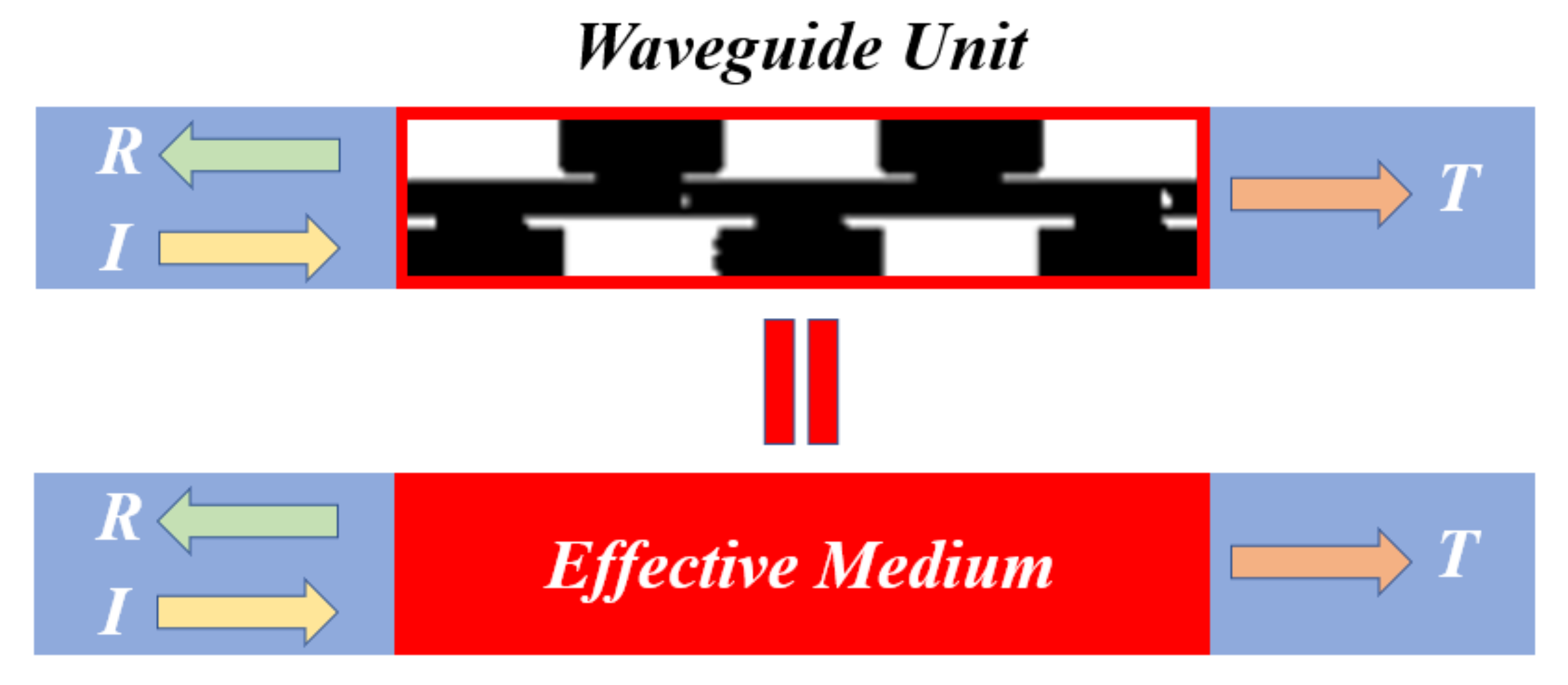
The waveguide unit proposed in this work can be replaced by a homogeneous effective medium (shown in Figure A1), which provides the same amplitude and phase of reflection and transmission coefficients. In Figure A1, the green, yellow and orange arrows represent incident, reflective and transmitted waves, respectively. When plane acoustic wave incident on the effective medium with density
and sound speed
placed between two different media with densities ,
and sound speeds ,
[21]:
where
is the acoustic impedance with
being the angle between the wave vector and layer normal.
is the phase change across the layer. f and d are incident frequency and the thickness of the effective medium, respectively. For the case of our design, both sides of the effective medium are identical, and the plane wave are normally incident on the effective medium. The reflection and transmission coefficients reduce to:
Introducing , and , we obtain:
In our work, both sides of the waveguide unit are air media (
kg/m3,
m/s). Therefore, the equivalent density and velocity (
and ) are associated with transmission and reflection coefficients (T and R) following Equations (A5) and (A6). By adopting finite element software, the transmission and reflection coefficients are easily to be calculated, and thus the equivalent density and velocity of the waveguide unit can be retrieved correspondingly.
Figure A1.
Schematic diagram of the effective medium method.

Appendix B. Mechanism of Coding Metalens
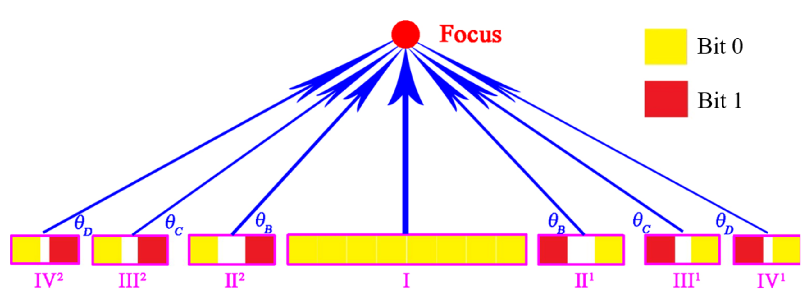
The acoustic metalens is an acoustic lens designed by metamaterial, through which the incident waves can be converted into focusing beam by taking advantage of the phase modulation. As shown in Figure A2, we take the coding method as an example to construct the metalens. We split the lens into several subunits (I, II1, II2, III1, III2, IV1, IV2) to analyze. According to the generalized Snell’s law, the refraction angle can be determined as follows at normal incidence (θi = 0):
where λ is the incident wavelength. At a fixed frequency, the refraction angle is depended on dφ(x)/dx. For region I (the center of the meta-lens), the refraction angle can be ignored because it is composed of the same cavities, which can be treated as traditional waveguides. For region II1, III1, and IV1, the refraction angles are diverse since the tangential phase gradients along the interface (dφ(x)/dx) are different. The refraction angles are only determined by the lengths of these regions when the phase difference, i.e., the value of ‘w’ is fixed. In this case, the refraction angles are inversely related to the region lengths. According to Equation (7), the length relationship of three regions (II1, III1, and IV1) is LB1>LC1>LD1. Thus, we could deduce that θB>θC>θD in a definite lens at a fixed incident wavelength due to the refraction angle relationship of three regions is (π/2-θII) < (π/2-θIII) < (π/2-θIV). Region II2, III2, and IV2 are mirror symmetric to region II1, III1, and IV1. In this acoustic system, therefore, the focusing is able to be achieved by designing the positions of the coding units meticulously.
Figure A2.
Schematic diagram of acoustic focusing by coding metalens.

References
- Danila, O. Polyvinylidene Fluoride-Based Metasurface for High-Quality Active Switching and Spectrum Shaping in the Terahertz G-Band. Polymers 2021, 13, 1860. [Google Scholar] [CrossRef] [PubMed]
- Dănilă, O.; Mănăilă-Maximean, D.; Bărar, A.; Loiko, V.A. Non-Layered Gold-Silicon and All-Silicon Frequency-Selective Metasurfaces for Potential Mid-Infrared Sensing Applications. Sensors 2021, 21, 5600. [Google Scholar] [CrossRef] [PubMed]
- Danila, O.; Manaila-Maximean, D. Bifunctional Metamaterials Using Spatial Phase Gradient Architectures: Generalized Reflection and Refraction Considerations. Materials 2021, 14, 2201. [Google Scholar] [CrossRef] [PubMed]
- Yang, S.; Page, J.H.; Liu, Z.; Cowan, M.L.; Chan, C.T.; Sheng, P. Focusing of Sound in a 3D Phononic Crystal. Phys. Rev. Lett. 2004, 93, 024301. [Google Scholar] [CrossRef] [Green Version]
- Tang, S.; Han, J.; Wen, T. Directional acoustic transmission based on metamaterials. AIP Adv. 2018, 8, 085312. [Google Scholar] [CrossRef]
- Park, C.M.; Kim, C.H.; Park, H.T.; Lee, S.H. Acoustic gradient-index lens using orifice-type metamaterial unit cells. Appl. Phys. Lett. 2016, 108, 124101. [Google Scholar] [CrossRef]
- McLeod, E.; Hopkins, A.B.; Arnold, C.B. Multiscale Bessel beams generated by a tunable acoustic gradient index of refraction lens. Opt. Lett. 2006, 31, 3155–3157. [Google Scholar] [CrossRef] [PubMed] [Green Version]
- Romero-García, V.; Cebrecos, A.; Picó, R.; Sánchez-Morcillo, V.J.; Garcia-Raffi, L.M.; Sánchez-Pérez, J.V. Wave focusing using symmetry matching in axisymmetric acoustic gradient index lenses. Appl. Phys. Lett. 2013, 103, 264106. [Google Scholar] [CrossRef] [Green Version]
- Chen, J.; Rao, J.; Lisevych, D.; Fan, Z. Broadband ultrasonic focusing in water with an ultra-compact metasurface lens. Appl. Phys. Lett. 2019, 114, 104101. [Google Scholar] [CrossRef]
- Tang, S.; Ren, B.; Feng, Y.; Song, J.; Jiang, Y. Asymmetric acoustic beam shaping based on monolayer binary metasurfaces. Appl. Phys. Express 2021, 14, 085504. [Google Scholar] [CrossRef]
- Wu, X.; Xia, X.; Tian, J.; Liu, Z.; Wen, W. Broadband reflective metasurface for focusing underwater ultrasonic waves with linearly tunable focal length. Appl. Phys. Lett. 2016, 108, 163502. [Google Scholar] [CrossRef]
- Tang, S.; Ren, B.; Feng, Y.; Song, J.; Jiang, Y. The generation of acoustic Airy beam with selective band based on binary metasurfaces: Customized on demand. Appl. Phys. Lett. 2021, 119, 071907. [Google Scholar] [CrossRef]
- Jahdali, R.A.; Wu, Y. High transmission acoustic focusing by impedance-matched acoustic meta-surfaces. Appl. Phys. Lett. 2016, 108, 031902. [Google Scholar] [CrossRef] [Green Version]
- Lin, Z.; Guo, X.; Tu, J.; Cheng, J.; Wu, J.; Huang, P.; Zhang, D. A collimated focused ultrasound beam of high acoustic transmission and minimum diffraction achieved by using a lens with subwavelength structures. Appl. Phys. Lett. 2015, 107, 113505. [Google Scholar] [CrossRef]
- Tang, S.; Ren, B.; Feng, Y.; Song, J.; Jiang, Y. Broadband acoustic focusing via binary rectangular cavity/Helmholtz resonator metasurface. J. Appl. Phys. 2021, 129, 155307. [Google Scholar] [CrossRef]
- Tang, S.; Wang, R.; Han, J.; Jiang, Y. Acoustic energy transport characteristics based on amplitude and phase modulation using waveguide array. J. Appl. Phys. 2020, 128, 165103. [Google Scholar] [CrossRef]
- Jiménez, N.; Romero-García, V.; García-Raffi, L.; Camarena, F.; Staliunas, K. Sharp acoustic vortex focusing by Fresnel-spiral zone plates. Appl. Phys. Lett. 2018, 112, 204101. [Google Scholar] [CrossRef]
- Zhu, Y.; Assouar, B. Multifunctional acoustic metasurface based on an array of Helmholtz resonators. Phys. Rev. B 2019, 99, 174109. [Google Scholar] [CrossRef]
- Tian, Y.; Wei, Q.; Cheng, Y.; Liu, X. Acoustic holography based on composite metasurface with decoupled modulation of phase and amplitude. Appl. Phys. Lett. 2018, 110, 191901. [Google Scholar] [CrossRef]
- Ghaffarivardavagh, R.; Nikolajczyk, J.; Holt, R.G.; Anderson, S.; Zhang, X. Horn-like space-coiling metamaterials toward simultaneous phase and amplitude modulation. Nat. Commun. 2018, 9, 1349. [Google Scholar] [CrossRef]
- Fokin, V.; Ambati, M.; Sun, C.; Zhang, X. Method for retrieving effective properties of locally resonant acoustic metamaterials. Phys. Rev. B 2007, 76, 144302. [Google Scholar] [CrossRef] [Green Version]
- Mei, J.; Wu, Y. Controllable transmission and total reflection through an impedance-matched acoustic metasurface. New J. Phys. 2014, 16, 123007. [Google Scholar] [CrossRef]
- Cao, L.; Yang, Z.; Xu, Y.; Assouar, B. Deflecting flexural wave with high transmission by using pillared elastic metasurface. Smart Mater. Struct. 2018, 27, 075051. [Google Scholar] [CrossRef]
Figure 1.
(a) Schematic of waveguide unit; (b) The correspondence between ‘w’ and phase/transmittance with c = 1; (c) The correspondence between ‘c’ and phase/transmittance with w = 8; (d) The correspondence between ‘w’, ‘c’ and phase; (e) The correspondence between ‘w’, ‘c’ and transmittance; (f) The correspondence between phase and transmittance.

Figure 2.
The relationship between equivalent density and velocity with (a) scale factor ‘w’ and (b) frequency. Here, c = 1.0, and ceff is equivalent velocity. (c) Acoustic field distribution in waveguide unit with w = 6 and its effective medium. The working frequency is 3430 Hz.
Figure 2.
The relationship between equivalent density and velocity with (a) scale factor ‘w’ and (b) frequency. Here, c = 1.0, and ceff is equivalent velocity. (c) Acoustic field distribution in waveguide unit with w = 6 and its effective medium. The working frequency is 3430 Hz.

Figure 3.
The amplitude of transmitted waves (red lines) and the effective acoustic impedance of waveguide unit (black lines) with different values of ‘c’. (a) c = 1.0; (b) c = 1.1; (c) c = 1.2; (d) c = 1.3; (e) c = 1.4; (f) c = 1.5; (g) c = 1.6; (h) c = 1.7; (i) c = 1.8. w and ceff are scale factor and equivalent velocity, respectively.

Figure 4.
The schematic diagram of the lens composed of five types of waveguide unit.

Figure 5.
(a) Acoustic focusing with different intensities at 3430 Hz. ‘Line 1, Line 2, Line 3, Line 4, Line 5′ are cut-lines of the focus; (b) Acoustic focusing with different focal lengths (the values of c and w for five types of waveguide units are c1 = c2 = c3 = c4 = c5 = 1.1, w1 = 5, w2 = 2, w3 = 18.5, w4 = 14, w5 = 9.) at 3430 Hz; (c) Acoustic focusing with different frequencies (the values of c and w for five types of waveguide units are c1 = c2 = c3 = c4 = c5 = 1.1, w1 = 5, w2 = 2, w3 = 18.5, w4 = 14, w5 = 9.); (d) Acoustic energy intensity curves with different cut-lines shown in Figure 4a; (e)Transmittance and phase shift curves with different parameter combinations.

Figure 6.
(a) The schematic diagram of the coding lens; (b) Acoustic focusing in lossless system and lossy system at 3430 Hz; (c) Pressure profile along the cut-line in two systems.
Figure 6.
(a) The schematic diagram of the coding lens; (b) Acoustic focusing in lossless system and lossy system at 3430 Hz; (c) Pressure profile along the cut-line in two systems.

Figure 7.
(a) Amplitude distribution along metasurface; (b) Phase distribution along metasurface; (c) Airy beam based on SPM; (d) Airy beam based on APM.
Figure 7.
(a) Amplitude distribution along metasurface; (b) Phase distribution along metasurface; (c) Airy beam based on SPM; (d) Airy beam based on APM.


Table 1.
The specific phase/amplitude value and corresponding parameters of c-w.
| Wavefront Modulation (c-w) | Phase (φ/2π) | |||||
|---|---|---|---|---|---|---|
| 0.2 | 0.4 | 0.6 | 0.8 | 1.0 | ||
| Amplitude | 0.2 | 0.81–29.5 | 1.46–20.0 | 1.7–19.5.0 | 1.76–13.0 | 3.7–11.6 |
| 0.4 | 1.18–28.5 | 1.27–20.0 | 1.548–17.0 | 1.53–8.0 | 2.8–8.2 | |
| 0.6 | 0.87–28.0 | 1.15–22.0 | 1.43–16.0 | 1.4–13.0 | 2.1–7.2 | |
| 0.8 | 1.10–28.0 | 1.08–23.2 | 1.365–16.0 | 1.25–13.0 | 1.53–8.0 | |
| 1.0 | 1.10–5.0 | 1.10–2.0 | 1.10–18.5 | 1.10–14.0 | 1.10–9.0 | |
Publisher’s Note: MDPI stays neutral with regard to jurisdictional claims in published maps and institutional affiliations. |
© 2021 by the authors. Licensee MDPI, Basel, Switzerland. This article is an open access article distributed under the terms and conditions of the Creative Commons Attribution (CC BY) license (https://creativecommons.org/licenses/by/4.0/).
Share and Cite
MDPI and ACS Style
Zhang, M.; Gu, G. Acoustic Focusing with Intensity Modulation Based on Sub-Wavelength Waveguide Array. Crystals 2021, 11, 1461. https://0-doi-org.brum.beds.ac.uk/10.3390/cryst11121461
AMA Style
Zhang M, Gu G. Acoustic Focusing with Intensity Modulation Based on Sub-Wavelength Waveguide Array. Crystals. 2021; 11(12):1461. https://0-doi-org.brum.beds.ac.uk/10.3390/cryst11121461
Chicago/Turabian StyleZhang, Mingran, and Guangrui Gu. 2021. "Acoustic Focusing with Intensity Modulation Based on Sub-Wavelength Waveguide Array" Crystals 11, no. 12: 1461. https://0-doi-org.brum.beds.ac.uk/10.3390/cryst11121461
Note that from the first issue of 2016, this journal uses article numbers instead of page numbers. See further details here.